KR890005132B1 - Apparatus for fluidizing a particulate material - Google Patents
Apparatus for fluidizing a particulate material Download PDFInfo
- Publication number
- KR890005132B1 KR890005132B1 KR1019850008428A KR850008428A KR890005132B1 KR 890005132 B1 KR890005132 B1 KR 890005132B1 KR 1019850008428 A KR1019850008428 A KR 1019850008428A KR 850008428 A KR850008428 A KR 850008428A KR 890005132 B1 KR890005132 B1 KR 890005132B1
- Authority
- KR
- South Korea
- Prior art keywords
- conveying
- gas
- plenum
- flow
- inlet
- Prior art date
Links
Images


Classifications
-
- F—MECHANICAL ENGINEERING; LIGHTING; HEATING; WEAPONS; BLASTING
- F23—COMBUSTION APPARATUS; COMBUSTION PROCESSES
- F23G—CREMATION FURNACES; CONSUMING WASTE PRODUCTS BY COMBUSTION
- F23G7/00—Incinerators or other apparatus for consuming industrial waste, e.g. chemicals
-
- B—PERFORMING OPERATIONS; TRANSPORTING
- B01—PHYSICAL OR CHEMICAL PROCESSES OR APPARATUS IN GENERAL
- B01J—CHEMICAL OR PHYSICAL PROCESSES, e.g. CATALYSIS OR COLLOID CHEMISTRY; THEIR RELEVANT APPARATUS
- B01J8/00—Chemical or physical processes in general, conducted in the presence of fluids and solid particles; Apparatus for such processes
- B01J8/0015—Feeding of the particles in the reactor; Evacuation of the particles out of the reactor
-
- F—MECHANICAL ENGINEERING; LIGHTING; HEATING; WEAPONS; BLASTING
- F23—COMBUSTION APPARATUS; COMBUSTION PROCESSES
- F23C—METHODS OR APPARATUS FOR COMBUSTION USING FLUID FUEL OR SOLID FUEL SUSPENDED IN A CARRIER GAS OR AIR
- F23C10/00—Fluidised bed combustion apparatus
- F23C10/18—Details; Accessories
- F23C10/22—Fuel feeders specially adapted for fluidised bed combustion apparatus
-
- F—MECHANICAL ENGINEERING; LIGHTING; HEATING; WEAPONS; BLASTING
- F23—COMBUSTION APPARATUS; COMBUSTION PROCESSES
- F23K—FEEDING FUEL TO COMBUSTION APPARATUS
- F23K3/00—Feeding or distributing of lump or pulverulent fuel to combustion apparatus
- F23K3/02—Pneumatic feeding arrangements, i.e. by air blast
Landscapes
- Engineering & Computer Science (AREA)
- Chemical & Material Sciences (AREA)
- Mechanical Engineering (AREA)
- General Engineering & Computer Science (AREA)
- Combustion & Propulsion (AREA)
- Organic Chemistry (AREA)
- Chemical Kinetics & Catalysis (AREA)
- Environmental & Geological Engineering (AREA)
- Air Transport Of Granular Materials (AREA)
- Fluidized-Bed Combustion And Resonant Combustion (AREA)
Abstract
내용 없음.No content.
Description
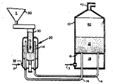
제1도는 미분탄과 황 흡수제를 유동층로에 공급하는 본 발명의 공급장치를 부분 절단하여 도시한 구성도.1 is a block diagram showing a partially cut supply of the present invention for supplying pulverized coal and sulfur absorbent to the fluidized bed furnace.
제2도는 본 발명의 공급장치의 단면도.2 is a cross-sectional view of the supply apparatus of the present invention.
제3도는 제2도의 선 3-3을 따른 확대 단면도.3 is an enlarged sectional view along line 3-3 of FIG.
* 도면의 주요부분에 대한 부호의 설명* Explanation of symbols for main parts of the drawings
10 : 유동층로 12 : 유동층10: fluidized bed furnace 12: fluidized bed
14 : 이송도관 16 : 층지지판14 conveying
18 : 공기 플리넘 20 : 공급장치18: air plenum 20: supply device
22 : 하우징 24 : 다공성 층지지판22 housing 24 porous layer support plate
26 : 가스 플리넘 28 : 입자유동 플리넘26: gas plenum 28: particle flow plenum
30 : 입자 공급수단 32 : 가스공급수단30: particle supply means 32: gas supply means
34 : 흐름통로 38 : 배출통로34: flow passage 38: discharge passage
42 : 염관 44 : 배출 파이프42: salt pipe 44: discharge pipe
50 : 저장실 60 : 이산층50: storage room 60: discrete layers
65 : 이산층 표면 70 : 비산 영역65: discrete layer surface 70: scattering region
80 : 니플 82 : 니플몸체80: nipple 82: nipple body
84 : 흐름통로 86 : 입구84: flow passage 86: entrance
88 : 출구88: exit
본 발명은 이송가스내의 입상재료를 이송 및 분배하기 위하여 유동시키는 장치에 관한 것으로서, 특히 이송가스내의 입상재료를 유동층로에 공급하기에 적합한 장치에 관한 것이다.BACKGROUND OF THE INVENTION 1. Field of the Invention The present invention relates to a device for flowing granular material in a conveying gas for conveying and distributing, and more particularly to an apparatus suitable for supplying particulate material in a conveying gas to a fluidized bed furnace.
오늘날 대표적인 유동층로에 있어서, 최대크기가 3.0 내지 6.5mm인 석탄과 같은 입상연료는 전형적으로 비교적 저온인 760 내지 925℃에서 비슷한 크기인 입상재료의 유동층내에 공급되어 연소된다. 만약 연소시킬 연료가 황을 함유하고 있으면, 층을 형성하는 입상재료는 가장 일반적인 석회석과 같은 황흡수제를 입상연료에 첨가하여 이루어진다. 연소공기로서 작용하는 유동공기는 층지지판 아래에 위치한 공기 플리넘으로부터 유동층으로 공급된다. 유동공기는 공기 플리넘으로부터 층지지판의 다수의 구멍을 통하여 유동층내의 입상재료를 유동시키기에 충분한 높은 흐름속도로 유동층내로 통과한다.In today's representative fluidized bed furnaces, particulate fuels such as coal with a maximum size of 3.0 to 6.5 mm are fed into and combusted in a fluidized bed of granular material of similar size, typically at relatively low temperatures of 760 to 925 ° C. If the fuel to be burned contains sulfur, the granular material that forms the layer is made by adding sulfur absorbents, such as the most common limestone, to the particulate fuel. Flowing air acting as combustion air is supplied to the fluidized bed from an air plenum located under the bed support plate. Flowing air passes from the air plenum through the plurality of holes in the bed support plate into the fluidized bed at a high flow rate sufficient to flow the granular material in the fluidized bed.
입상재료를 층으로 공급하기 위하여 상부층공급 시스템과 하부층 공급시스템을 포함한 많은 다른 시도가 행해져 왔다. 입상재료를 유동층에 공급하기에 적합한 한 특수한 하부층 공급 시스템은 미합중국 특허 제4,356,779호에 기재되어 있다. 상기 특허에 기재된 바와같이 연료공급기는 공기에 연료를 연행시키고 연료를 연소로 안으로 상향 공급하기 위해 유동층연소로 아래에 배치된다. 공급기 하우징은 수평 배치된 다공성 분배판에 의해 상부 및 하부로 분리되는 격실을 한정한다. 유동층에 공급될 입상연료는 이송공기가 다공성 분배판 아래의 하부 격실로 공급되는 동안 다공성 분배판 위의 상부격실로 공급된다. 하부 격실로 공급된 공기는 다공성 분배판을 통하여 상향으로 흘러 격실의 상부 영역의 미분탄을 유동시켜 연행시킨다. 연행된 미분탄은 공급기의 지붕을 통해 유동 플리넘으로 통하여 이송도관을 통하여 격실로부터 유동층 보일러로 상향이송된다. 미합중국 특허 제4,356,779호에 기재된 공급기에서는 개개의 이송도관의 각각을 통해 입상재료의 배출을 제어할 수 있는 설비가 없다. 공급기로부터 단부점까지의 이송도관의 길이가 동일하다고 가정하면, 상기 특허의 공급기로부터의 입상재료의 배출은 공급기로부터 안내되는 각종 이송도관으로 반드시 균등하게 분배될 것이다. 배출의 불균등 또는 선택적인 분배를 허용할 설비, 또는 균등하지 않는 이송도관의 길이로 인한 배출의 원래의 불균등한 분배를 보상할 설비는 없다.Many other attempts have been made to supply granular material in layers, including an upper layer supply system and a lower layer supply system. A special lower layer supply system is described in US Pat. No. 4,356,779, as long as it is suitable for supplying particulate material to the fluidized bed. As described in the patent, the fuel feeder is disposed below the fluidized bed combustion furnace to entrain the fuel to air and to feed the fuel up into the combustion furnace. The feeder housing defines a compartment separated up and down by a horizontally disposed porous distribution plate. The granular fuel to be supplied to the fluidized bed is supplied to the upper compartment above the porous distribution plate while the conveying air is supplied to the lower compartment below the porous distribution plate. Air supplied to the lower compartment flows upward through the porous distribution plate and flows through the pulverized coal in the upper region of the compartment. Entrained pulverized coal is conveyed upwards from the compartment to the fluidized bed boiler through the conveying conduit through the roof of the feeder and into the plenum plenum. In the feeder described in US Pat. No. 4,356,779, there is no facility for controlling the discharge of particulate material through each of the individual feed conduits. Assuming that the length of the feed conduit from the feeder to the end point is the same, the discharge of particulate material from the feeder of the patent will necessarily be evenly distributed to the various feed conduits guided from the feeder. There is no facility to allow for disproportionate or selective distribution of emissions, or to compensate for the original uneven distribution of emissions due to unequal lengths of conveying conduits.
이런 단점에 대한 공급기 장치는 1984년 2월 3일 죠셉 알.캄파라토의 이름으로 출원되고 일반양도된 계류중인 미합중국 특허원 제576,599호에 기재되어 있다. 공급기는 판에 양간 인접한 가스 플리넘과 판에 초인접한 입자유동 플리넘내로 가로질러 배치된 다공성 층지지판에 의해 불할되는 격실을 한정하는 하우징을 구비한다. 가스공급수단은 판에 초인접한 유동입상재료의 이산층을 형성하도록 입상 유동 플리넘에 퇴적된 입상 재료를 유동시키도록 다공성 층지지판을 통해 가압이송가스를 상향으로 이송시키기 위해 가스 플리넘안으로 개방된다. 입상재료는 하우징의 지붕을 관통하고 하향 연장되는 공급 기둥을 통하여 유동 플리넘에 공급되고, 층 지지판 근처에 종료되어, 입상재료가 이산층의 표면 아래의 위치에 있는 결실로 공급되게 한다. 또한, 수직하게 위치할 수 있는 복수개의 이송도관은 입자 유동 플리넘으로 연장되어, 비산영역으로부터 입상재료와 이송가스를 수용하도록 이산층으이 표면위의 원하는 거리에서 비산영역안으로 개방된다.A feeder device for this drawback is described in pending U.S. Patent Application No. 576,599, filed on February 3, 1984, in the name of Joseph R. Camparato. The feeder has a housing defining a compartment defined by a gas plenum bilaterally adjacent to the plate and a porous layer support plate disposed across into the particle flow plenum superadjacent to the plate. The gas supply means is opened into the gas plenum to convey pressurized gas upward through the porous layer support plate to flow the granular material deposited in the granular flow plenum to form a discrete layer of fluidized granular material superadjacent to the plate. . The granular material is fed to the flow plenum through a supply column extending downwardly through the roof of the housing and terminated near the layer support plate, causing the granular material to be supplied to the deletion at a position below the surface of the discrete layer. In addition, the plurality of transfer conduits, which can be positioned vertically, extend into the particle flow plenum and open into the scattering region at a desired distance on the surface of the discrete layer to receive the granular material and the conveying gas from the scattering region.
이산층의 표면에 대해 이송도관의 위치를 독립적으로 조절함으로써, 어떠한 특수한 이송도관을 통하여 흐르는 고상물질이 다양해질 수 있다. 이송도관을 수직으로 조정하기 위하여 밀봉수단이 제공되어야 하며, 이는 입자가 가스 플리넘내로 통과하는, 것을 막기위하여 입자유동 플리넘으로부터 가스를 밀봉하는 동안 지지판을 통한 도관의 수직 이동을 허용한다.By independently adjusting the position of the transfer conduit with respect to the surface of the discrete layer, the solid material flowing through any particular transfer conduit can be varied. Sealing means must be provided to adjust the delivery conduit vertically, which allows vertical movement of the conduit through the support plate while sealing the gas from the particle flow plenum to prevent particles from passing into the gas plenum.
본 발명의 목적은 입상재료의 배출을 공급장치에서 안내되는 다수의 이송도관 중에서 선택적으로 분배할 수 있도록 이송가스에서 입상재료를 유동시키는 장치를 제공하는 것이다.It is an object of the present invention to provide an apparatus for flowing granular material in a conveying gas so as to selectively distribute the discharge of the granular material among a plurality of conveying conduits guided by the feeder.
본 발명의 다른 목적은 공급창치에서 안내되는 이송도관을 통하여 입상재료의 배출을 이송도관의 이동없이 조정할 수 있는 입상재료의 유동장치를 제공하는 것이다.Another object of the present invention is to provide a flow apparatus of granular material which can adjust the discharge of the granular material through the conveying conduit guided by the supply window without moving the conveying conduit.
본 발명의 장치는 격실을 가로질러 하우징내에 배치된 다공성 층 지지판에 의하여 가스 플리넘과, 그 위의 입자유동 플리넘으로 분할되는 격실을 한정하는 하우징을 포함한다. 가스공급수단은 다공성 층지지판의 가스통로를 통하여 상향 통과시키기 위하여 가스 플리넘을 통하여 가압 이송가스를 이송하기 위해 가스 플리넘내로 연통한다. 상향 통과하는 이송가스는 입자 유동 플리넘내의 입상재료를 유동시켜 층지지판에 초인접한 유동된 입상재료인 이산층과 이산층 위의 비산영역이 하우징내에 형성되게 한다. 유동된 입상재료의 소량은 상향 통과하는 이송가스의 기포가 이산층의 표면에 통하여 분출함으로써 이산층으로부터 비산영역으로 이송된다.The apparatus of the present invention includes a housing defining a compartment divided into a gas plenum and a particle flow plenum thereon by a porous layer support plate disposed in the housing across the compartment. The gas supply means communicates into the gas plenum for conveying pressurized conveying gas through the gas plenum for upward passage through the gas passage of the porous layer support plate. The upwardly passing conveying gas flows the granular material in the particle flow plenum so that a discrete layer, which is a flowed granular material superadjacent to the layer support plate, and a scattering region on the discrete layer are formed in the housing. The small amount of the granular material that is flowed is transferred from the discrete layer to the scattering region by bubbles of the conveying gas passing upward through the surface of the discrete layer.
입자공급수단은 하우징을 관통하고 유동 플리넘내로 연장되어, 이산층의 표면 하단 위치에 형성된 유동층내에 입상재료를 퇴적시킨다. 또한 복수개의 이송도관도 하우징을 관통하고 입자유동 플리넘내로 연장되어, 이산층의 표면위의 원하는 거리에서 비산영역내로 통하게 된다. 이송도관은 비산영역으로부터 입상재료와 이송가스를 수용하고, 이 이송가스에 있는 입상재료를 유동층로의 연소실과 같은 원하는 목적지로 이송한다.The particle supply means penetrates through the housing and extends into the flow plenum to deposit particulate material in the fluidized bed formed at the bottom surface of the discrete layer. The plurality of conveying conduits also penetrate the housing and extend into the particle flow plenum, leading into the scattering region at a desired distance on the surface of the discrete layer. The conveying conduit receives the granular material and the conveying gas from the scattering zone and conveys the granular material in the conveying gas to a desired destination, such as a combustion chamber in a fluidized bed.
본 발명에 따라서 오리피스형 니플수단은 이송 도관중 적어도 하나의 입구에 교체 가능하게 설치되어 있다. 오리피스형 니플수단은 이와 합체된 이송도관으로 향하는 입구의 단면적보다 작은 단면적으로 갖는 비산영역으로 통하는 입구를 갖는다. 또한 오리피스형 니플수단은 이와 합체된 이송도관의 입구를 통하는 출구를 포함하는데, 출구의 단면적은 입구의 단면적보다 커서 분기 흐름통로가 니플수단의 입구로부터 출구로 한정된다.According to the invention the orifice-shaped nipple means is replaceably installed at the inlet of at least one of the conveying conduits. The orifice-type nipple means has an inlet leading to the scattering area having a cross-sectional area smaller than the cross-sectional area of the inlet toward the conveying conduit incorporated therein. The orifice nipple means also includes an outlet through the inlet of the conveying conduit incorporated therein, the cross-sectional area of the outlet being greater than the cross-sectional area of the inlet so that the branch flow passage is defined from the inlet to the outlet of the nipple means.
본 발명의 다른 목적, 특징 및 장점은 입상재료를 유동층로에 공급하는데 사용되는 공급장치가 있는 본 발명의 유동공급장치의 적합한 실시예와 첨부된 도면을 참조로 하여 하기에 상세히 설명된다.Other objects, features and advantages of the present invention are described in detail below with reference to the accompanying drawings and a suitable embodiment of the present invention of a fluid supply device having a supply device for supplying particulate material to a fluidized bed furnace.
제1도는 유동층로(10)를 도시한 것으로서, 미분탄과 같은 황함유 연료는 산화황 흡수제를 함유한 입상재료의 유동층(12)에서 연소된다. 전형적으로 산화황 흡수제는 석회석, 석회, 돌로마이트 및 소다회로 구성되는 그룹에서 선택한다. 본원에서 언급하는 석회석이라함은 돌로마이트, 석회 또는 소다회를 포함하지만 이에 제한되지 않는 산화황 흡수제를 망라하는 것이고 미분탄이라 함은 다른 입상연료를 포함한다.FIG. 1 shows a fluidized bed furnace 10 in which sulfur-containing fuels such as pulverized coal are combusted in a fluidized bed 12 of particulate material containing a sulfur oxide absorbent. Typically the sulfur oxide absorbent is selected from the group consisting of limestone, lime, dolomite and soda cycles. Limestone referred to herein encompasses sulfur oxide absorbers, including but not limited to dolomite, lime or soda ash, and pulverized coal includes other particulate fuels.
미분탄은 유동공급장치(2)로부터 층지지판(16)을 통하여 층내로 상향 연장되는 복수개의 이송도관(14)을 통해 로의 유동층(12)에 공급된다. 연소공기는 유동층 지지판(16)하단에 위치한 공기 플리넘(18)에 공급되고, 유동층(12)내의 입상재료를 유동시키기에 충분한 높은 유속으로 공기 플리넘(18)으로부터 층지지판(16)내의 복수개의 공기구를 통하여 유동층(12)내로 들어간다. 미분탄은 유동층(12)내에서 연소되고, 프리보드(freeboard)영역(40)에서 뜨거운 연관가스가 형성되어 염관(42)을 통하여 하류의 증기발생기(비도시)로 유동층로(10)를 빠져나간다.Pulverized coal is supplied from the flow supply device 2 to the fluidized bed 12 of the furnace through a plurality of transfer conduits 14 extending upwardly into the bed through the
본 발명의 공급장치(20)는 유동층로(10)옆에 배치되고 이송도관(14)으로 서로 연결되어 있는데, 이송도관(14)은 이송장치(20)로부터 하향 연장되고, 유도층로(10)에 평행하게 연장된후, 층지지판(16)을 통해 상향연장되어 유동층(12)에 연통된다. 공급장치(20)는 하우징(22), 적합하게는 실린더형 하우징을 갖는데, 하우징은 다공성 층지지판(24)에 의해 층지지판(24)하단에 배치된 가스 플리넘(26)과 층지지판(24)상단에 배치된 입자유동 플리넘(28)으로 분리되는 격실을 한정한다.The supply device 20 of the present invention is arranged next to the fluidized bed 10 and connected to each other by a transfer conduit 14, the transfer conduit 14 extends downward from the transfer device 20, the induction bed 10 After extending in parallel to), it is extended upward through the
이송가스(7)는 하우징(22)의 통로를 통하여 층지지판(24)하단의 가스 플리넘(26)내로 연통되는 가스공급수단(32)을 통하여 유동공급장치(20)내로 들어간다. 가압된 이송가스(7)는 가스 플리넘(26)에 공급된후 다공성 층지지판(24)의 다수의 흐름 통로(34)를 통하여 상향되어 유동 플리넘(28)에 공급된 입상재료(5)가 유동됨으로써 층지지판(24)에 초인접한 유동재료의 이산층(60)의 유동재료의 이산층 위에 비산영역(70) 형성된다.The conveying gas 7 enters into the flow supply apparatus 20 through the gas supply means 32 which communicates through the passage of the housing 22 to the gas plenum 26 below the layer support plate 24. The pressurized conveying gas 7 is supplied to the gas plenum 26 and then up through the plurality of flow passages 34 of the porous layer support plate 24 and is supplied to the granular material 5 supplied to the flow plenum 28. By flowing, the scattering region 70 is formed on the discrete layer of the fluidized material of the discrete layer 60 of the fluidized material superimposed on the layer support plate 24.
복수개의 이송도관(14)은 공급장치(20)의 하우징(22)을 관통하며, 유동층로(10)에서의 유동층(12)과 공급장치(20)를 상호연결시켜주는 다수의 흐름통로를 제공한다. 이송도관(14)은 하우징(22)의 유동 플리넘(28)내로 연장되어 이산층 위에서 얼마간 이격된 즉, 이산층(60)과 비산영역(70)사이의 계면을 형성하는 이산층의 표면(65)위에서 얼마간 이격된 비산영역(70)내로 연통되어 있다. 이송도관(14)은 유동 플리넘(28)의 비산영역(70)으로부터 입상재료와 이송가스를 받고 이송가스내의 받은 입상재료를 공급장치(20)로부터 로(10)의 유동층(12)으로 이송한다.The plurality of conveying conduits 14 pass through the housing 22 of the feeder 20 and provide a plurality of flow passages that interconnect the fluidized bed 12 and the feeder 20 in the fluidized bed 10. do. The transfer conduit 14 extends into the flow plenum 28 of the housing 22 and is spaced some distance over the discrete layer, i.e., the surface of the discrete layer forming an interface between the discrete layer 60 and the scattering region 70 ( 65 is communicated into the scattering region 70 spaced apart some above. The conveying conduit 14 receives the granular material and the conveying gas from the scattering region 70 of the flowing plenum 28 and conveys the received granular material in the conveying gas from the supply device 20 to the fluidized bed 12 of the furnace 10. do.
유동층로로의 이송시에 미분탄인 유동시킬 입상재료는 석회석과 같은 산화황 입상 흡수제와 함께 또는 단독으로 저장실(50)로부터 입자 공급수단(40)을 통해서 통상의 공급기를 경유하여 공급장치(20)의 유동 플리넘(28)에 공급된다. 적합하게 입자 공급수단(30)은 하우징(22)의 덮개를 관통하고 이산층(60)내로 하향 연장되는 공급관을 포함하여, 그 사이를 통과하는 입상재료가 다공성 층지지판(24)에 초근접한 지점의 표면(64)하단의 이산층(60)내에 쌓이게 한다. 입자공급수단(30)내에 유지된 입상재료의 기둥은 유동 플리넘(28)내의 압력으로부터 공급기와 저장실(50)을 밀봉하는 재료 헤드를 형성한다. 다른방법으로 2-밸브 갑문실과 같은 통상의 밀봉수단을 공급장치(20)의 격실내의 압력에 대한 밀봉용으로 사용할 수 있다.The granular material to be pulverized during the transfer to the fluidized bed is supplied with a sulfur oxide granular absorbent such as limestone or alone from the storage chamber 50 through the particle supply means 40 via a conventional feeder. Is supplied to the flowing plenum 28. The particle supply means 30 suitably comprise a feed tube penetrating the lid of the housing 22 and extending downward into the discrete layer 60, where the granular material passing therebetween is in close proximity to the porous layer support plate 24. In the discrete layer 60 at the bottom of the surface 64. The column of granular material held in the particle supply means 30 forms a material head that seals the feeder and the reservoir 50 from the pressure in the flow plenum 28. Alternatively, conventional sealing means, such as a two-valve lock chamber, can be used for sealing against pressure in the compartment of the feeder 20.
다공성 층지지판(24)은 공급장치(20)의 하우징(22)내에 배치되어 도면에 도시한 바와같이 적합한 하향 경사면을 이루도록 오목한 상향 원추형 접시의 형태를 취한다. 배출통로(38)는 경사진 층지지판(24)의 하부에 배치되어 있다. 배출 파이프(44)는 유동 플리넘(28)로부터 어떠한 유동되지 않은 입상재료도 받기 위해 경사진 층지지판(24)에 있는 배출 통로(38)를 향해 그 상단부가 열려 있다. 배출 파이프(44)는 유동 플리넘(28)로부터 배출 파이프(44)를 통과하는 유동되지 않는 입상재료를 제거하기 위해 하우징(22)으로 외향 연장되어 있다.The porous layer support plate 24 takes the form of an upwardly conical plate which is arranged in the housing 22 of the feeder 20 to form a suitable downward slope as shown in the figure. The discharge passage 38 is disposed below the inclined layer support plate 24. The
하우징(22)을 관통하고 유동 플리넘(28)내로 연장된 다수의 이송도관(14)은 비산영역(70)으로부터 입상재료와 이송가스를 받기 위해 이산층(60)의 표면(65)위에 선택된 거리에서 비산영역(70)내로 통해 있다. 입상 재료는 이송가스를 상향 통과하는 기포가 이산층(60)의 표면(65)으로부터 비산영역(70)내로 분출할때 이산층(60)으로부터 비산영역(70)내로 이송된다.A plurality of transfer conduits 14 penetrating the housing 22 and extending into the flow plenum 28 are selected on the surface 65 of the discrete layer 60 to receive particulate material and transfer gas from the scattering zone 70. Through the scattering area 70 at a distance. The granular material is transferred from the discrete layer 60 into the scattering region 70 when bubbles passing upwardly through the conveying gas are ejected from the surface 65 of the discrete layer 60 into the scattering region 70.
이송가스의 속도가 초당 약 3미터(10피트)인 경우에 양호하게 한정된 표면(65)을 갖는 유동성 입상재료의 이산층(60)이 형성된다. 이산층(60)내의 입자밀도는 이송가스 0.45Kg(1파운드)당 입상재료 450Kg(1000파운드)으로써 비교적 높은 값으로 균일하다. 표면(65)에서 상기 입자밀도가 갑작스럽게 급격히 떨어지는 경우가 있는데, 그러면 비산영역으로의 거리가 증가함에 따라 즉, 이산층의 표면위로의 거리가 증가함에 따라 연속 감소된다.When the velocity of the conveying gas is about 3 meters (10 feet) per second, a discrete layer 60 of flowable granular material is formed having a well defined surface 65. The particle density in the discrete layer 60 is uniform at a relatively high value as 450 Kg (1000 lb) of granular material per 0.45 Kg (1 lb) of conveying gas. There is a case where the particle density drops abruptly and suddenly at the surface 65, which then decreases continuously as the distance to the scattering region increases, i.e. as the distance over the surface of the discrete layer increases.
비산영역(70)에서 평균입자 밀도는 투입된 입자의 흐름 속도의 함수일 것으로 생각할 수 있다. 즉, 비산영역(70)내로의 입상재료의 도입은 공정이 제어된 변위일 것으로 믿어진다. 따라서 평형층 수중이 전형적으로 이송도관(14)의 통로 하단의 몇 센티미터 내외로 한번 설정되면, 층표면(65)으로부터 비산영역(70)내로의 입상재료의 분출 속도는 이산층(60)의 표면 하단부에서 층으로 통하는 입자 공급 수단(30)을 통하여 이산층(60)으로 투입되는 입상재료의 투입속도와 동일하게 된다.The average particle density in the scattering region 70 can be thought of as a function of the flow rate of the injected particles. In other words, it is believed that the introduction of particulate material into the scattering region 70 is a process controlled displacement. Thus, once the equilibrium water is typically set to within a few centimeters of the bottom of the passageway of the conveying conduit 14, the rate of ejection of the granular material from the layer surface 65 into the scattering area 70 is determined by the surface of the discrete layer 60. It is equal to the feeding rate of the granular material introduced into the discrete layer 60 through the particle supply means 30 leading from the lower end to the layer.
이송도관(14)이 어떤 적합한 단면형상을 갖는 튜브형 부재일지라도, 제2도에 도시한 본 발명의 장치의 적합한 실시예에 도시된 이송도관(14)은 입자 공급 수단(30)과 하우징(22)사이의 환상 공간에서 외주연에 일정간격으로 배치된 원형 단면인 복수개의 고정식으로 연장되 튜브형 부재를 포함한다. 이송도관(14)은 하우징(22)을 하단으로부터 관통하여 가스 플리넘(26),다시 층지지판(24)을 통해 상향으로 수직 연장되어 이산층(60)을 이산층(60)의 표면(65)위의 일정거리에서 비산영역(70)내로 통하게 한다.Although the delivery conduit 14 is a tubular member having any suitable cross-sectional shape, the delivery conduit 14 shown in a suitable embodiment of the apparatus of the present invention shown in FIG. 2 is provided with a particle supply means 30 and a housing 22. It includes a plurality of fixedly extending tubular members of circular cross-section arranged at regular intervals on the outer periphery in the annular space therebetween. The transfer conduit 14 extends vertically upward through the gas plenum 26 and back layer support plate 24 through the housing 22 from the bottom to allow the discrete layer 60 to surface 65 of the discrete layer 60. ) Into the scattering area 70 at a predetermined distance above.
본 발명에 따라서 각각의 이송도관(14)은 그 개방단부에 고체 가능하게 설치된 단부가 개방된 오리피스형 니플수단(80)을 구비하고 있다. 각각의 니플(80)은 유동 플리넘으로 통하는 입구(86)으로부터 니플이 설치되는 이송도관의 흐름 통도를 통하는 출구(88)로 연장되는 분기되는 흐름 통로(84)를 한정하는 니플몸체(82)를 포한한다. 각각의 니플(80)의 출구(88)의 단면적과 이송도관(14)의 흐름 통로로 향한 입구의 단면적보다 작다. 따라서 각각의 니플(80)의 입구(86)는 오리피스로 작용하고, 따라서 이에 관련된 이송도관을 통하는 흐름을 효과있게 조절한다. 따라서 이송도관(14)을 통하여 흐르는 이송가스에 연행된 입상재료의 출량은 알맞게 크거나 작은 입구(86)를 갖는 니플(80)을 제공함으로써 선택적을 증가 또는 감소된다.According to the present invention, each conveying conduit 14 is provided with an orifice-type nipple means 80 having an open end provided in a solid manner at its open end. Each nipple 80 has a
고정식 이송도관(14)과 관련하여 교체가능한 니플(80)을 사용함으로써, 복수개의 이송도관 사이에서 입상재료와 이송가스의 흐름을 조정하기 위한 기계적으로 간단하고 저렴한 수단이 제공된다. 공급장치(20)와 유동층로(10)사이에서 동일길이의 이송도관을 제공하지 못하는 경우에는, 어떠한 도관을 통하는 압력 강하가 그 길이에 직접 비례하는 것에 기인하여 이송도관을 통하는 흐름에 불균형이 고유적으로 존재한다. 도관을 통하는 흐름이 그 사이에서의 압력 강하와 관련이 있기 때문에, 보다 짧은 길이의 도관을 통하는 입상재료의 흐름은 보다 긴 길이의 도관을 통하는 그것보다 크다. 그러나 알맞은 크기의 입구를 갖는 니플을 제공함으로써, 니플입구의 오리피스 효과는 도관 길이의 변화에 관련된 맞지 않은 압력강하를 보상하는데 사용할 수 있으므로 흐름의 불균형의 제거되고 다른 길이의 도관을 통하는 입상재료와 이송가스의 균일한 흐름이 제공된다.By using replaceable nipples 80 in connection with the stationary conveying conduit 14, a mechanically simple and inexpensive means for regulating the flow of particulate material and conveying gas between the plurality of conveying conduits is provided. If it is not possible to provide the same length of conveying conduit between the feeder 20 and the fluidized bed furnace 10, the imbalance inherent in the flow through the conveying conduit is due to the pressure drop through any conduit directly proportional to its length. Exist as an enemy. Since the flow through the conduit is related to the pressure drop in between, the flow of particulate material through the shorter conduit is greater than that through the longer length conduit. However, by providing a nipple with an appropriately sized inlet, the orifice effect of the nipple inlet can be used to compensate for an unsuitable pressure drop associated with a change in conduit length, thus eliminating flow imbalances and transferring granular material and conduits through conduits of different lengths. A uniform flow of gas is provided.
니플몸체는 이에 설치된 이송도관과 잘맞는 단면 형상을 가지며 절두체형 쉘의 기부로부터 외향으로 연장되는 슬리브를 갖는 단부가 개방된 절두체형 쉘을 구비한다. 슬리브는 이송도관의 입구로의 삽입에 의해 니플몸체를 이송도관의 개방 단부에 미끄럼 설치하기에 적합하게 되어 있다. 절두체형 쉘인 니플몸체는 본래자체 청정되는 경사진 외부 표면을 갖는다.The nipple body has an open-ended frustum shaped shell having a cross-sectional shape that fits well with the conveying conduit installed therein and having a sleeve extending outwardly from the base of the frustrated shell. The sleeve is adapted to slide the nipple body at the open end of the delivery conduit by insertion into the inlet of the delivery conduit. The nipple body, which is a frustum shaped shell, has an inclined outer surface that is inherently cleaned.
도면에 도시한 장치의 실시예에서 이송도관(14)은 단면이 원형인 연장된 튜브형 부재이고, 절두체형 니플모체(82)는 제3도에 도시한 바와 같이 원추형 쉘(83)의 큰 직경 단부로부터 외향 연장되는 실린더형 슬리브(85)를 갖는 개방 단부 절두체인 원추형 쉘(83)을 포함한다. 실린더형 슬리브(85)는 이송도관(14)의 내경보다 단지 약간 작은 외경을 가져서 니플(80)을 이송도관(14)의 개방 단부에 미끄럼 설치할 수 있도록 되어 있다.In the embodiment of the device shown in the figure, the feed conduit 14 is an elongated tubular member of circular cross section, and the
부수적으로 원추형 쉘(83)은 본래 자체 청정되는 외부표면을 제공한다. 외부표면이 충분히 급경사진 원추형몸체를 제공함으로써, 입상재료는 원추형 몸체의 외부표면에 달라어 쌓이기 보다는 미끄러져 내린다.Incidentally,
본 발명은 입상재료를 이송가스에서 다수의 단부점으로 이송하기 위하여 유동시킬 공급장치를 제공하는데, 공급기에서 안내되는 어떤 특수한 이송도관을 통한 공급기의 출력은 안내되는 어떤 특수한 이송도관을 통한 공급기의 출력은 이에 합체된 오리피스형 니플을 알맞게 크거나 작은 입구를 갖는 또다른 오리피스형 니플로 단순히 교체함으로써 다른 이송도관에 대하여 변화시킬 수 있다.The present invention provides a feeder for flowing granular material in order to transfer the granular material from the feed gas to a plurality of end points, wherein the output of the feeder through any special conveying conduit guided by the feeder is the output of the feeder through any special conveying conduit guided. Can be changed for other transfer conduits by simply replacing the orifice-shaped nipple incorporated therein with another orifice-shaped nipple with a moderately large or small inlet.
본 발명의 공급장치(20)를 유동층로(10)에 공급하는 장치로 도시했지만, 본 발명의 공급장치(20)는 이송가스에서의 입상재료를 둘 또는 그 이상의 단부점에 이송하고자 하는 어떠한 경우에서도 이용할 수 있다.Although the supply device 20 of the present invention is shown as a device for supplying the fluidized bed furnace 10, the supply device 20 of the present invention is intended to convey the granular material in the conveying gas to two or more end points. Also available at.
따라서, 본 발명은 첨부된 청구의 범위에 의한 기술사상과 범주로써 제한된다.Accordingly, the invention is limited only by the spirit and scope of the appended claims.
Claims (4)
Applications Claiming Priority (3)
| Application Number | Priority Date | Filing Date | Title |
|---|---|---|---|
| US06/670,730 US4593630A (en) | 1984-11-13 | 1984-11-13 | Apparatus for fluidizing a particulate material in a conveying gas |
| US670.730 | 1984-11-13 | ||
| US670730 | 1991-03-18 |
Publications (2)
| Publication Number | Publication Date |
|---|---|
| KR860004273A KR860004273A (en) | 1986-06-20 |
| KR890005132B1 true KR890005132B1 (en) | 1989-12-11 |
Family
ID=24691627
Family Applications (1)
| Application Number | Title | Priority Date | Filing Date |
|---|---|---|---|
| KR1019850008428A KR890005132B1 (en) | 1984-11-13 | 1985-11-12 | Apparatus for fluidizing a particulate material |
Country Status (5)
| Country | Link |
|---|---|
| US (1) | US4593630A (en) |
| JP (2) | JPS61119514A (en) |
| KR (1) | KR890005132B1 (en) |
| CN (1) | CN1003886B (en) |
| IN (1) | IN162908B (en) |
Families Citing this family (13)
| Publication number | Priority date | Publication date | Assignee | Title |
|---|---|---|---|---|
| SE460617B (en) * | 1985-06-20 | 1989-10-30 | Asea Stal Ab | SET FOR DRYING, CRUSHING AND DISTRIBUTION OF SOLID BRAINSLE FOR SOLID BRAINS |
| FR2586366B1 (en) * | 1985-08-22 | 1988-02-12 | Sames Sa | POWDER RECOVERY METHOD AND DEVICE FOR CARRYING OUT SAID METHOD |
| US4733621A (en) * | 1987-05-08 | 1988-03-29 | A. Ahlstrom Corporation | Apparatus and methods for operating a fluidized bed reactor |
| SE462446B (en) * | 1989-06-29 | 1990-06-25 | Abb Stal Ab | COUNCIL CONTAINER FOR BEDDING MATERIAL AT A POWER PLANT WITH A BRAIN CHAMBER FOR FLUIDIZED BED |
| SE9403268L (en) * | 1994-09-29 | 1996-03-30 | Abb Carbon Ab | Method and apparatus for feeding fuel to a fluidized bed |
| KR100355505B1 (en) * | 1998-06-16 | 2002-10-12 | 미츠비시 쥬고교 가부시키가이샤 | Operating method of fluidized-bed incinerator and the incinerator |
| DE10260738A1 (en) * | 2002-12-23 | 2004-07-15 | Outokumpu Oyj | Process and plant for conveying fine-grained solids |
| US20090047613A1 (en) * | 2005-03-29 | 2009-02-19 | Kadant Black Clawson Inc. | Method and Apparatus for Pneumatic Drying of Lime Mud |
| CN100588966C (en) * | 2006-12-30 | 2010-02-10 | 中国科学院过程工程研究所 | Gas-solid reaction kinetic parameter analyzer |
| FI120515B (en) * | 2008-02-08 | 2009-11-13 | Foster Wheeler Energia Oy | Circulating fluidized bed reactor for oxygen combustion and method of operating such a reactor |
| PL429573A1 (en) * | 2016-06-08 | 2019-10-07 | Gas Technology Institute | Method and the device for distribution of solid fuel materials at a uniform rate |
| DE102016111291A1 (en) * | 2016-06-21 | 2017-12-21 | Thyssenkrupp Ag | Apparatus and method for heat treatment of mineral material |
| EP3739262B1 (en) * | 2019-05-13 | 2021-06-09 | Doosan Lentjes GmbH | Fluidized bed apparatus |
Family Cites Families (9)
| Publication number | Priority date | Publication date | Assignee | Title |
|---|---|---|---|---|
| EP0025080B1 (en) * | 1979-06-08 | 1984-02-08 | BABCOCK-BSH AKTIENGESELLSCHAFT vormals Büttner-Schilde-Haas AG | Process and arrangement for feeding comminuted solid fuel to a fluidized bed furnace |
| US4275668A (en) * | 1980-08-28 | 1981-06-30 | Foster Wheeler Energy Corporation | Coal feed system for a fluidized bed combustor |
| US4335661A (en) * | 1980-09-24 | 1982-06-22 | Foster Wheeler Energy Corporation | Fluidized bed heat exchanger having an air assisted bed drain |
| JPS57160826A (en) * | 1981-03-30 | 1982-10-04 | Nippon Steel Corp | Powder distribution control device |
| US4357883A (en) * | 1981-08-10 | 1982-11-09 | Combustion Engineering, Inc. | Bed drain cover assembly for a fluidized bed |
| US4349969A (en) * | 1981-09-11 | 1982-09-21 | Foster Wheeler Energy Corporation | Fluidized bed reactor utilizing zonal fluidization and anti-mounding pipes |
| US4445443A (en) * | 1982-03-31 | 1984-05-01 | Foster Wheeler Energy Corporation | Fluidized bed heat exchanger having separating drain and method of operation thereof |
| US4434726A (en) * | 1982-12-27 | 1984-03-06 | Combustion Engineering, Inc. | Fine particulate feed system for fluidized bed furnace |
| DE3305078C1 (en) * | 1983-02-14 | 1984-06-14 | Hoechst Ag, 6230 Frankfurt | Pipe switch for pipelines for the conveyance of solids |
-
1984
- 1984-11-13 US US06/670,730 patent/US4593630A/en not_active Expired - Fee Related
-
1985
- 1985-09-24 IN IN676/CAL/85A patent/IN162908B/en unknown
- 1985-10-10 CN CN85107500.2A patent/CN1003886B/en not_active Expired
- 1985-11-12 KR KR1019850008428A patent/KR890005132B1/en not_active IP Right Cessation
- 1985-11-13 JP JP60252977A patent/JPS61119514A/en active Pending
-
1990
- 1990-11-30 JP JP1990129028U patent/JPH053469Y2/ja not_active Expired - Lifetime
Also Published As
| Publication number | Publication date |
|---|---|
| JPH0372525U (en) | 1991-07-22 |
| CN85107500A (en) | 1986-05-10 |
| CN1003886B (en) | 1989-04-12 |
| US4593630A (en) | 1986-06-10 |
| JPH053469Y2 (en) | 1993-01-27 |
| JPS61119514A (en) | 1986-06-06 |
| IN162908B (en) | 1988-07-23 |
| KR860004273A (en) | 1986-06-20 |
Similar Documents
| Publication | Publication Date | Title |
|---|---|---|
| KR890005132B1 (en) | Apparatus for fluidizing a particulate material | |
| FI92099B (en) | Circulating fluidized bed reactor | |
| KR920702406A (en) | Processes and apparatus for gasifying gasifiers and / or reforming gases and high temperature heat exchangers for practicing the method | |
| JPS6023855B2 (en) | Fluidized bed reactor | |
| US4535706A (en) | Fluidised beds | |
| CN105492854A (en) | Feed flow conditioner for particulate feed materials | |
| CA1191741A (en) | Liquid fuel and air feed apparatus for fluidized bed boiler | |
| US3958916A (en) | Distributor plate | |
| CA1154319A (en) | Solid fuel feed system for a fluidized bed | |
| CA1332685C (en) | Composite circulating fluidized bed boiler | |
| US5230868A (en) | Fluidized bed reactor with protected fluid distributor | |
| US4148437A (en) | Combustor | |
| US4441822A (en) | Apparatus for mixing and distributing solid particulate material | |
| US4530290A (en) | Apparatus for fluidizing a particulate material in a conveying gas | |
| US4185942A (en) | Material transfer system | |
| US4738569A (en) | Apparatus for fluidizing a particulate material in a conveying gas | |
| US4433631A (en) | Method and apparatus for producing a useful stream of hot gas from a fluidized bed combustor while controlling the bed's temperature | |
| US4315469A (en) | Method and device for distributing liquid fuel to a fluidized bed | |
| EP0251247A1 (en) | Power plant with combustion of a fuel in a fluidized bed | |
| US4943190A (en) | Aeration tube discharge control device with variable fluidic valve | |
| CA1157708A (en) | Method and apparatus for feeding solid fuels into a fluidized-bed furnace | |
| CA1120333A (en) | Fluidized bed firing | |
| GB2132500A (en) | Classification and recycling of fluidised bed material | |
| CA1075588A (en) | Combustor | |
| JP2672016B2 (en) | Solid particle feeder for fluidized bed |
Legal Events
| Date | Code | Title | Description |
|---|---|---|---|
| A201 | Request for examination | ||
| E902 | Notification of reason for refusal | ||
| G160 | Decision to publish patent application | ||
| E701 | Decision to grant or registration of patent right | ||
| GRNT | Written decision to grant | ||
| FPAY | Annual fee payment |
Payment date: 19921005 Year of fee payment: 4 |
|
| LAPS | Lapse due to unpaid annual fee |