KR890004930B1 - Hermetic compressor - Google Patents
Hermetic compressor Download PDFInfo
- Publication number
- KR890004930B1 KR890004930B1 KR1019860005458A KR860005458A KR890004930B1 KR 890004930 B1 KR890004930 B1 KR 890004930B1 KR 1019860005458 A KR1019860005458 A KR 1019860005458A KR 860005458 A KR860005458 A KR 860005458A KR 890004930 B1 KR890004930 B1 KR 890004930B1
- Authority
- KR
- South Korea
- Prior art keywords
- frame
- container
- compressor
- scroll member
- oil
- Prior art date
Links
- XDTMQSROBMDMFD-UHFFFAOYSA-N C1CCCCC1 Chemical compound C1CCCCC1 XDTMQSROBMDMFD-UHFFFAOYSA-N 0.000 description 1
Images


Classifications
-
- F—MECHANICAL ENGINEERING; LIGHTING; HEATING; WEAPONS; BLASTING
- F04—POSITIVE - DISPLACEMENT MACHINES FOR LIQUIDS; PUMPS FOR LIQUIDS OR ELASTIC FLUIDS
- F04C—ROTARY-PISTON, OR OSCILLATING-PISTON, POSITIVE-DISPLACEMENT MACHINES FOR LIQUIDS; ROTARY-PISTON, OR OSCILLATING-PISTON, POSITIVE-DISPLACEMENT PUMPS
- F04C18/00—Rotary-piston pumps specially adapted for elastic fluids
- F04C18/02—Rotary-piston pumps specially adapted for elastic fluids of arcuate-engagement type, i.e. with circular translatory movement of co-operating members, each member having the same number of teeth or tooth-equivalents
- F04C18/06—Rotary-piston pumps specially adapted for elastic fluids of arcuate-engagement type, i.e. with circular translatory movement of co-operating members, each member having the same number of teeth or tooth-equivalents of other than internal-axis type
-
- F—MECHANICAL ENGINEERING; LIGHTING; HEATING; WEAPONS; BLASTING
- F04—POSITIVE - DISPLACEMENT MACHINES FOR LIQUIDS; PUMPS FOR LIQUIDS OR ELASTIC FLUIDS
- F04C—ROTARY-PISTON, OR OSCILLATING-PISTON, POSITIVE-DISPLACEMENT MACHINES FOR LIQUIDS; ROTARY-PISTON, OR OSCILLATING-PISTON, POSITIVE-DISPLACEMENT PUMPS
- F04C29/00—Component parts, details or accessories of pumps or pumping installations, not provided for in groups F04C18/00 - F04C28/00
-
- C—CHEMISTRY; METALLURGY
- C08—ORGANIC MACROMOLECULAR COMPOUNDS; THEIR PREPARATION OR CHEMICAL WORKING-UP; COMPOSITIONS BASED THEREON
- C08F—MACROMOLECULAR COMPOUNDS OBTAINED BY REACTIONS ONLY INVOLVING CARBON-TO-CARBON UNSATURATED BONDS
- C08F14/00—Homopolymers and copolymers of compounds having one or more unsaturated aliphatic radicals, each having only one carbon-to-carbon double bond, and at least one being terminated by a halogen
- C08F14/02—Monomers containing chlorine
- C08F14/04—Monomers containing two carbon atoms
- C08F14/06—Vinyl chloride
-
- F—MECHANICAL ENGINEERING; LIGHTING; HEATING; WEAPONS; BLASTING
- F04—POSITIVE - DISPLACEMENT MACHINES FOR LIQUIDS; PUMPS FOR LIQUIDS OR ELASTIC FLUIDS
- F04C—ROTARY-PISTON, OR OSCILLATING-PISTON, POSITIVE-DISPLACEMENT MACHINES FOR LIQUIDS; ROTARY-PISTON, OR OSCILLATING-PISTON, POSITIVE-DISPLACEMENT PUMPS
- F04C18/00—Rotary-piston pumps specially adapted for elastic fluids
- F04C18/02—Rotary-piston pumps specially adapted for elastic fluids of arcuate-engagement type, i.e. with circular translatory movement of co-operating members, each member having the same number of teeth or tooth-equivalents
-
- F—MECHANICAL ENGINEERING; LIGHTING; HEATING; WEAPONS; BLASTING
- F04—POSITIVE - DISPLACEMENT MACHINES FOR LIQUIDS; PUMPS FOR LIQUIDS OR ELASTIC FLUIDS
- F04C—ROTARY-PISTON, OR OSCILLATING-PISTON, POSITIVE-DISPLACEMENT MACHINES FOR LIQUIDS; ROTARY-PISTON, OR OSCILLATING-PISTON, POSITIVE-DISPLACEMENT PUMPS
- F04C23/00—Combinations of two or more pumps, each being of rotary-piston or oscillating-piston type, specially adapted for elastic fluids; Pumping installations specially adapted for elastic fluids; Multi-stage pumps specially adapted for elastic fluids
- F04C23/008—Hermetic pumps
-
- F—MECHANICAL ENGINEERING; LIGHTING; HEATING; WEAPONS; BLASTING
- F04—POSITIVE - DISPLACEMENT MACHINES FOR LIQUIDS; PUMPS FOR LIQUIDS OR ELASTIC FLUIDS
- F04C—ROTARY-PISTON, OR OSCILLATING-PISTON, POSITIVE-DISPLACEMENT MACHINES FOR LIQUIDS; ROTARY-PISTON, OR OSCILLATING-PISTON, POSITIVE-DISPLACEMENT PUMPS
- F04C2240/00—Components
- F04C2240/60—Shafts
- F04C2240/603—Shafts with internal channels for fluid distribution, e.g. hollow shaft
-
- Y—GENERAL TAGGING OF NEW TECHNOLOGICAL DEVELOPMENTS; GENERAL TAGGING OF CROSS-SECTIONAL TECHNOLOGIES SPANNING OVER SEVERAL SECTIONS OF THE IPC; TECHNICAL SUBJECTS COVERED BY FORMER USPC CROSS-REFERENCE ART COLLECTIONS [XRACs] AND DIGESTS
- Y10—TECHNICAL SUBJECTS COVERED BY FORMER USPC
- Y10S—TECHNICAL SUBJECTS COVERED BY FORMER USPC CROSS-REFERENCE ART COLLECTIONS [XRACs] AND DIGESTS
- Y10S417/00—Pumps
- Y10S417/902—Hermetically sealed motor pump unit
-
- Y—GENERAL TAGGING OF NEW TECHNOLOGICAL DEVELOPMENTS; GENERAL TAGGING OF CROSS-SECTIONAL TECHNOLOGIES SPANNING OVER SEVERAL SECTIONS OF THE IPC; TECHNICAL SUBJECTS COVERED BY FORMER USPC CROSS-REFERENCE ART COLLECTIONS [XRACs] AND DIGESTS
- Y10—TECHNICAL SUBJECTS COVERED BY FORMER USPC
- Y10T—TECHNICAL SUBJECTS COVERED BY FORMER US CLASSIFICATION
- Y10T29/00—Metal working
- Y10T29/49—Method of mechanical manufacture
- Y10T29/49229—Prime mover or fluid pump making
- Y10T29/49236—Fluid pump or compressor making
- Y10T29/4924—Scroll or peristaltic type
Abstract
Description
제1도는 본 발명의 1실시예를 나타낸 밀폐형 스크로울 압축기의 종단면도.1 is a longitudinal cross-sectional view of a hermetic scroll compressor showing an embodiment of the present invention.
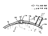
제2도는 밀폐용기의 동(胴)체부의 용접 접합부와 통로 가이드부의 확대부분 사시도.2 is an enlarged perspective view of a welded joint and a passage guide of a copper body portion of a sealed container.
제3도는 밀폐용기의 동체부의 용접 접합부와 프레임의 연통로 부분을 나타낸 부분 횡단면도.3 is a partial cross-sectional view showing a part of a communication path between the welded joint and the frame of the fuselage of the sealed container.
제4도는 제1도의 IV-IV선 횡단면도.4 is a cross-sectional view taken along the line IV-IV of FIG.
제5도는 제1도의 V-V선 횡단면도.5 is a cross-sectional view taken along line V-V in FIG.
제6도는 본 발명의 응용 변형예를 나타낸 종단면도.6 is a longitudinal sectional view showing an application modification of the present invention.
제7도는 제6도의 VII-VII선 부분 종단면도.7 is a partial longitudinal cross-sectional view taken along line VII-VII of FIG. 6;
제8도는 밀폐형 스크로울 압축기의 횡단면도.8 is a cross-sectional view of a hermetic scrawl compressor.
제9도는 밀폐용기의 동체부의 용접 접합부와 프레임의 단면을 나타낸 부분도.9 is a partial view showing a cross section of the welded joint and the frame of the body portion of the sealed container.
제10도는 프레임 외주부의 기름 누설 상태를 나타낸 부분 종단면도이다.10 is a partial longitudinal cross-sectional view showing the oil leakage state of the outer peripheral portion of the frame.
* 도면의 주요부분에 대한 부호의 설명* Explanation of symbols for main parts of the drawings
1 : 밀폐용기 1m : 용접 접합부1: sealed container 1m: welding joint
1m' : 용기내돌출부 2a : 상부 토출실1m ': In-projection protrusion 2a: Upper discharge chamber
2b : 하부실 2c : 하부전동기실2b:
3 : 전동기 3a : 전동기 스테이터3: motor 3a: motor stator
5 : 고정 스크로울 부재 5a : 경판5: fixed scroll member 5a: hard board
5b : 랩 6 : 선회 스크로울부재5b: wrap 6: turning scroll member
7 : 흡입구 8 : 압축실7: suction port 8: compression chamber
10 : 토출구 11 : 프레임10 discharge port 11 frame
11m : 프레임 외주부 11p, 11q : 간극11m: frame outer periphery 11p, 11q: gap
12 : 오울덤 기구 14 : 회전축12: Oulder Mechanism 14: rotation axis
14a : 편심축 14b : 전동기축14a:
17 : 흡입관 18, 18a, 18b : 연통로17:
19 : 토출관 11n : 용접 접합부19: discharge pipe 11n: welding joint
본 발명은 냉동·공조용의 냉매 압축기 혹은 헬륨용 압축기로서 사용되는 밀폐형 스크로울 압축기이고, 특히 오일(oil)분리 기능을 갖는 밀폐용기를 구비한 밀폐형 스크로울 압축기에 관한 것이다.BACKGROUND OF THE
밀폐용기내에 전동기로 구동되는 스크로울 압축기를 내장한 밀폐형 스크로울 압축기의 밀폐용기에 대해서는 미국특허 제4, 545, 747호 등에 개시되어 있다. 밀폐용기는 전동기를 연설한 스크로울 압축기를 내장하고, 이 밀폐용기는 상용기, 용기동체부와 하용길로 이루어진다. 압축기부 및 전동기부가 설치되는 프레임 부분은 용기 동체부의 내벽면에 외관상 밀착되어 고정되어 있다. 이 고정구조는 제8도에 나타낸 바와같이 프레임(11)의 외주부(11m)와 용기 동체부(1b)의 내벽면이 수축 끼워맞춤(shrinkage fit)에 의하여 고착되어 있다. 또 이 용기 동체부(1b)는 박판재를 원통 형상으로 말아서 그 양단부를 용접(전기 아아크 용접법)으로 접합시켜 형성하고 있다.A hermetic container of a hermetic scrawl compressor incorporating a scrawl compressor driven by an electric motor in a hermetic container is disclosed in US Patent No. 4, 545, 747 and the like. The airtight container is equipped with a scrawl compressor which speaks an electric motor, and this airtight container consists of a commercial vessel, a container body part, and a roadway. The frame part in which the compressor part and the electric motor part are installed is fixed to the inner wall surface of the container body part in close contact. As shown in FIG. 8, the fixing structure is fixed to the outer peripheral portion 11m of the frame 11 and the inner wall surface of the
제9도에 나타낸 바와같이 종래의 구조에서는 용접 접합부(1m)에는, 용기 내부에 돌출된 돌출부(1m')가 형성된다. 이것은 접합부의 강도를 유지하는데 필요한 두께인 것이다.As shown in Fig. 9, in the conventional structure, the weld joint 1m is provided with a protrusion 1m 'protruding inside the container. This is the thickness required to maintain the strength of the joint.
이 접합부(1m)의 양측에는 상기 돌출부(1m')의 영향으로 용기 동체부(1b)가 용접 공정시에 용기 자체가 변형되고, 결과적으로 프레임(11)의 외주면(11m)에 대하여 간극이 형성된다. 이 용접 접합부(1m)는 용기 동체부(1b)의 축 방향으로 뻗어 형성된다. 제9도에 나타낸 바와같이 용접 접합부(1m)에는 용치 동체부(1b)에 대하여 층진구조가 불가피하게 생기게 된다. 이와같이 실질적으로는 연통로(18)를 제외하고 토출실과 전동기실과의 시일(seal)성이 완정하지 않게 된다.On both sides of this joint 1m, the container itself deforms during the welding process of the
또 상기 접합부(1m)의 근방에 토출관(19)이 배치되어 있을 경우에는, 토출관의 밀폐용기 동체부에이 용접시에 다시 열이 가해져서 상기 간극(11p, 11q)이 커지는 일도 있다.In addition, when the
원래 냉매 가스와 기름이 통하는 통로는 연통로(18)(18a, 18b)이지만 상술한 용접 접합부(1m)의 둘레에는 간극(11p, 11q)이 있기 때문에, 이 간극을 거쳐 상부토출실(2a)로부터 하부실(2b)로 오일이 새어 들어가게 된다.Originally, the passage through which the refrigerant gas and oil pass is the communication paths 18 (18a and 18b), but since the gaps 11p and 11q are around the weld joint 1m described above, the upper discharge chamber 2a passes through this gap. Oil leaks from the
상기 간극(11p, 11q)으로부터 누설된 오일은 그대로 토출측으로 유출하게 된다. 제9도에 나타낸 바와같이, 토출관(19)의 근방에 용기 동체부의 접합부(11m)가 위치하고 있으면, 상부 토출실내의 오일이 상기 프레임 외주부의 간극(11p, 11q)을 거쳐 하부실에 새어들러가기 용이해지고 나아가서는 토출관(19)에 직접 오일이 기기(機器)밖으로 유출된다. 그 상태를 제10도에 나타낸다. 또한 스크로울 압축이의 내부에 있어서는 오일의 흐름은(여기서는 생략한다) 통상 밀폐용기내의 가스와 오일은 상기한 바와같이 상부 토출실(2a)로부터 연통로(18a, 18b)를 거쳐 하부실(2b)에 도달하고 여기서 비교적 넓은 공간이 되므로 가스 유속이 저하되어 냉매 가스중의 오일은 분리된다.Oil leaked from the gaps 11p and 11q flows out to the discharge side as it is. As shown in FIG. 9, when the junction part 11m of a container body part is located in the vicinity of the
그러나, 상기 프레임의 간극(11p, 11q)이 토출관(19)의 근방 혹은 연통로(18b)와 토출관의 중간에 있으면, 이 간극(11p, 11q)을 거쳐 상부 토출실(2a)의 오일이 직접기외(機外)로 유출하는 결과가 되어 밀폐용기(1)전체의 오일 분리효율이 반감된다. 상기 간극(11p, 11q)으로부터 새는 오일의 량은 상부 토출실(2a)과 하부실(2b)의 압력차에 비례하여 증가하므로, 스크로울 압축기가 인버터 구동에 의하여 고속 운전되면, 더욱 용기 자체의 오일 상승량이 증대한다. 또 상기 간극 (11p, 11q)의 크기는 용접시의 열 변형의 정도에 따라 변화하고, 이들의 간극은 일정하지가 않다. 따라서 이것은 상부 토출실(2a)의 오일이 그 간극을 거쳐 기외로 유출하는 량(오일 상승량)의 불균일로서 나타난다.However, if the gaps 11p and 11q of the frame are in the vicinity of the
이와같이 용접 접합부의 간극은 용기 자체의 오일 상승량을 조장시키고 또한 오일 상승량의 불균일에도 큰 요인이 될수있는 것으로서 제품의 품질관리의 면에서도 문제가 된다.In this way, the gap between the welded joints promotes the oil rising amount of the container itself and can also be a big factor in the unevenness of the oil rising amount, which is a problem in terms of product quality control.
본 발명의 목적은, 밀폐용기 동체부의 용접 접합부의 변형이 프레임 외주에 누설 간극을 형성하지 않도록 하고, 설정 유통로 이외의 누설 통로가 형성되는 일이 없고, 밀폐용기내의 오일을 효율적으로 분리하고, 오일이 기외로 유출하는 것을 방지하는 밀폐용기 구조를 제공하는 것을 목적으로 한다.The object of the present invention is to prevent the deformation of the welded joint of the sealed container body from forming a leakage gap in the outer periphery of the frame, and to prevent the leakage passage other than the set flow path, and to separate the oil in the sealed container efficiently. An object of the present invention is to provide an airtight container structure which prevents oil from flowing out of the air.
상기 목적을 달성하기 위하여, 본 발명은 밀폐용기 동체부의 용접 접합부가 층이진 형상으로 되어도 이 접합부를 상부 토출실과 하부실과를 연통하는 연통로부에 위치시키고 연통로 이외의 프레임 외주부는 밀폐용기와 밀착시키고 상기 프레임 외주부에는 누설 간극이 존재하지 않도록 구성한 특징을 가진다.In order to achieve the above object, in the present invention, even if the welded joint of the airtight container body has a layered shape, the joint is placed in the communication path communicating the upper discharge chamber and the lower chamber, and the frame outer circumference other than the communication path closely adheres to the airtight container. And a leakage gap does not exist in the outer periphery of the frame.
상기 구성에 의하여 토출가스와 함께 상부 토출실로 토출된 오일은 토출가스와 함께 설정 연통로만을 유통하여 하부실로 흐르고 전동기의 주위에 고루 미치도록 흐르고, 전동기 및 밀폐용기 내벽에 접하여 오일이 분리됨과 동시에 전동기를 냉각하고 오일이 기외로 유출되는 량을 저감하고, 또 오일분리 효율은 각 압축기가 모두 일정하게 확보되어 압축기의 신뢰성 향상도 도모할 수 있다.The oil discharged to the upper discharge chamber together with the discharge gas flows to the lower chamber by flowing only the set communication path with the discharge gas and flows evenly around the motor, and the oil is separated by contacting the inner wall of the motor and the sealed container. The cooling rate is reduced, and the amount of oil flowing out to the outside is reduced, and the oil separation efficiency is uniformly secured for each compressor, thereby improving the reliability of the compressor.
본 발명의 1실시예를 도면에 의거하여 설명한다.An embodiment of the present invention will be described with reference to the drawings.
제1도는 밀폐형 스크로울 압축기의 전체 구조를 나타낸다. 밀폐용기(1)내의 위쪽에 압축기부가 아래쪽에 전동기부가 수납되어 있다. 그리고 밀폐용기(1)내는 상부 토출실(2a)과 하부실(2b)로 구획되어 있다.1 shows the overall structure of a hermetic scroll compressor. The motor section is housed below the compressor section above the sealed
압축기부는 고정 스크로울 부재(5)와 선회 스크로울 부재(6)를 서로 맞물리게 하여 압축실(밀폐공간)(8)을 형성하고 있다. 고정 스크로울 부재(5)는 원판 형상의 경판(鏡板)(5a)이고, 이에 직립하여 임보류트 곡선 혹은 이에 근사한 곡선으로 형성된 랩(5b)으로 이루어지고 그 중심부에 토출구(10), 외주부에 흡입구(7)를 구비하고 있다. 선회 스크로울 부재(6)는 원판형상의 경판(6a)과 이에 직립하여 고정스크로울의 랩과 동일한 형상으로 형성된 랩(6b)과 경판의 반(反)랩면에 형성된 보스(6c)로 이루어져 있다. 프레임(11)은 중압부에 축받이부를 형성하고 이 축받이부에 회전축(14)이 지지되고, 회전축 선단의 편심축(14a)은 상기 보스(6c)에 선회 운동이 가능하도록 삽입되어 있다.The compressor unit forms the compression chamber (closed space) 8 by engaging the
또 프레임(11)에는 고정 스크로울 부재(5)가 복수개의 볼트에 의하여 고정되고, 선회 스크로울 부재(6)는 오울덤(oldham) 기구(12)에 의하여 프레임(11)에 지지되고 선회 스크로울 부재(6)는 고정 스크로울 부재(5)에 대하여 자전(自轉)하지 않고 선회운동을 하도록 형성되어 있다. 회전축(14)에는 하부에 전동기축(14b)을 일체로 연설하여 전동기부를 직결하고 있다. 고정 스크로울 부재(5)의 흡입구(7)에는 밀폐용기(1)를 관통하여 수직 방향의 흡입관(17)이 접속되고, 토출구(10)가 개구되어있는 상부 토출실(2a)은 통로(18a), (18b) 및 토출통로 가이드(40)를 거쳐 하부실(2b)과 연통되어 있다. 이 하부실(2b)은 전동기 스테이터(3a)와 밀폐용기(1)측벽과의 사이의 통로(45)를 거쳐 하부 전동기실(2c)에 연통되어 있다. 또, 하부실(2b)은 밀폐용기(1)를 관통하는 토출관(19)에 연통되어 있다.In addition, the fixed
또한 11f는 전동기(3)를 프레임측에 고정하기 위한 프레임 대좌부(台座部)이다. 또, 토출통로 가이드(40)는 전동기의 냉각작용을 도모하기 위하여 냉매가스와 오일을 전동기(3)까지 직접 안내하기 위하여 설치한 부품이고, 상세한 구조를 이하에 설명한다.11f is a frame base part for fixing the
제2도 내지 제5도는 용기 동체부(1b)의 용접 접합부(1n)와 기타의 압축기 내부의 구성부재(프레임(11)의 연통로(18b) 및 전동기(3)의 스테이터(3a)등) 와의 위치 관계를 명시하고 있다.2 to 5 show weld joints 1n of the
제2도와 제3도에 있어서, 용접 접합부(1n)는 토출통로 가이드(40) 및 프레임(11)의 외주부에 설치된 연통로(18b)와 대향된 위치에 설정되어 있다. 원래 이 통로(40a)와 통로(18b)는 냉매가스와 압축기내의 윤활과 냉각 작용을 하는 오일이 지나가는 통로이고 용접 접합부(1n)의 양단에 파생(波生)되는 층이진 부(1n')가 그대로 남아 있어도 양자의 흐름을 저해하는 것은 아니다. 이 접합부(1n)의 용기 내부로 돌출한 돌출부(1n')는 이것과 대향하는 부재(예를들면 고정스크로울(5)의 외주부, 프레임(11)의 외주부, 전동기(3)의 스테이터 외주부등)와는 절결부로서 형성되는 통로(18a, 18b) 및 전동기(3)의 스테이터(3a)의 외주부의 공간(45)(제4도와 제5도 참조)으로 완전히 떨어져 있어 접촉될 우려가 없다. 그러므로 돌출부(1n')는 그대로 남겨두어도 압축기를 조립하는데 아무런 문제는 없다. 종래 기술에서는 이 용접 접합부의 돌출부는 프레임(11)의 외주부와 접촉되어 있고, 조립면에서도 이 돌출부가 클 경우에는 그 돌출부가 깎아 제거해야 한다는 불필요한 작업을 불가피하게 해야 된다는 상황을 가져온다. 이와같이 본 발명에서는 가공, 조립성인 면에서도 종래의 기기에 비하여 고정수 저감의 효과(제품 가격의 저렴화)가 있다.In FIG. 2 and FIG. 3, the welding joint part 1n is set in the position which opposes the
제4도와 제5도에 나타낸 바와같이, 밀폐용기 동체부(1b)를 형성하는 박판재의 용접 접합부(1n)에 대하여 대략 반대의 위치에 가스를 토출하고 토출관(19)을 용기 동체부에 설치하고 있다. 이것은 오일과 가스가 흐르는 통로계(예를들면 18a, 18b 나 45)에 대하여 극력 원격의 위치관계가 되도록 토출관을 설정하고, 그러므로 밀폐용기내에서의 가스와 오일이 지나가는 유로 길이를 가장 길게 유지하고, 이 과정에서 냉매 가스중으로부터 오일을 분리하는 것이다.As shown in FIG. 4 and FIG. 5, a gas is discharged in the substantially opposite position with respect to the welding joint 1n of the thin plate which forms the airtight
제1도에 나타낸 바와같이, 본 발명에서는 용기동체부(1b)의 용접 접합부(1n)를 연통로 측(18)(18a, 18b)에 설정함으로써 밀폐용기(1)내를 프레임(11)으로 두개로 분할된 구조로서 사부 토출실 2a―→연통로(18)―→하부실(2b)―→토출관(19)에 이르는 유로계 이외의 부분에 시일성 즉 상부 공간의 토출실(2a)과 하부실(2b)과의 시일성(밀봉성)을 확실하게 가지게 할 수가 있게 된다. 또한 이 시일성을 가지는 범위는 연통로(18b)를 제외한 프레임(11)의 외주부이다. 상기 프레임(1)의 외주부의 시일성은 압축 기구부(스크로울 부(5, 6)와 프레임(11)등의 조립품)를 용기 동체부(1b)에 압입하므로써 형성된다.As shown in FIG. 1, in the present invention, the welded joint 1n of the
상기한 바와같이, 본 실시예에서는 밀폐용기의 동체부(1b)를 박판재를 원통형상으로 감는 구조 즉 권판(卷板)구조를 전제로 하여 그 최적인 밀폐챔버에 대하여 설명하였으나 권판 구조가 아닌 경우도 연통로 이외의 프레임 외주를 밀폐용기에 밀착시키면 오일 상승량을 저감시키고 오일 분리 효율을 일정하게 확보할 수가 있다.As described above, in the present embodiment, the optimum closed chamber is described on the assumption that the
본 발명의 응용예로서 그 실시예를 제6도와 제7도에 나타낸다. 밀폐용기(100)의 동체부(70)는 시임레스(seamless)강관을 사용한 소위 시임레스 챔버이다. 제6도는 타원형 챔버의 모양을 의식적으로 나타낸 것이고, 그 동체부의 돌출부(70a)를 프레임(11)의 연통로(18b)측에 배치하고, 반대 위치의 돌출부(70b)를 토출관측에 배치한다. 단, 토출관측의 프레임(11)의 외주부의 간극(70p)에는 내열성의 수지재(내 냉매성이 있는 실리콘 고무등)(71)을 충전하여 상부 토출실(2a)과 하부실(2b)과의 시일성을 확보하고 있다.Examples of the application of the present invention are shown in FIG. 6 and FIG. The
이와같이 프레임(11)의 연통로(18b) 이외의 프레임 외주부(11m)에서 용기 동체부와 사이에 간극이 있을 경우 상기한 내냉매성 및 내열성이 있는 수지재(71)를 그 간극부에 충전하여 시일한다.In this way, when there is a gap between the container body part and the frame outer peripheral part 11m other than the
이와같이 본 실시에에서는 용접 접합부 주위의 밀폐용기 동체부의 변형이 오일 상승량 그 자체에 전혀 영향을 미치지 않으므로 각 압축기마다의 오일 분리 작용의 불균일은 감소되고 제품의 품질이 향상된다. 또 종래 기술에서 볼수 있었던 바와같은 오일이 밀폐용기 동체부의 간극을 통하여 상부 토출실(2a)로부터 하부실(2b)로 흐르고 직접토출관으로 유출되는 것과같은 단락적인 흐름이 없어지므로 오일은 토출가스와 동시에 흐르고 전동기의 주위에 고루 미치도록 흐리기 때문에 오일에 의한 전동기의 냉각 효과를 더울 향상시킬수가 있다.Thus, in this embodiment, since the deformation of the airtight container body around the weld joint does not affect the oil lift amount at all, the non-uniformity of oil separation action for each compressor is reduced and the quality of the product is improved. In addition, since oil, as seen in the prior art, flows from the upper discharge chamber 2a to the
또 오일 분리면에서 용접 접합부의 층이진 구조로 인한 오일의 단락적인 흐름을 저지하기 때문에 밀폐형 스크로울 압축기의 최적의 용접 접합부의 위치관계를 명시하고 있으나 이것은 압축기의 조립성의 면에서도 양호한 결과를 주게된다.In addition, because it prevents the short-circuit flow of oil due to the layered structure of the weld joint on the oil separation surface, it specifies the positional relationship of the optimum weld joint of the hermetic compressor, but this also gives a good result in terms of assembly of the compressor. .
Claims (3)
Applications Claiming Priority (3)
| Application Number | Priority Date | Filing Date | Title |
|---|---|---|---|
| JP60-179414 | 1985-08-16 | ||
| JP85-179414 | 1985-08-16 | ||
| JP60179414A JPS6248988A (en) | 1985-08-16 | 1985-08-16 | Closed type scroll compressor |
Publications (2)
| Publication Number | Publication Date |
|---|---|
| KR870002380A KR870002380A (en) | 1987-03-31 |
| KR890004930B1 true KR890004930B1 (en) | 1989-11-30 |
Family
ID=16065449
Family Applications (1)
| Application Number | Title | Priority Date | Filing Date |
|---|---|---|---|
| KR1019860005458A KR890004930B1 (en) | 1985-08-16 | 1986-07-07 | Hermetic compressor |
Country Status (4)
| Country | Link |
|---|---|
| US (1) | US4696629A (en) |
| JP (1) | JPS6248988A (en) |
| KR (1) | KR890004930B1 (en) |
| DE (1) | DE3626806A1 (en) |
Families Citing this family (25)
| Publication number | Priority date | Publication date | Assignee | Title |
|---|---|---|---|---|
| US5219281A (en) * | 1986-08-22 | 1993-06-15 | Copeland Corporation | Fluid compressor with liquid separating baffle overlying the inlet port |
| US4911620A (en) * | 1988-05-12 | 1990-03-27 | Tecumseh Products Company | Scroll compressor top cover plate |
| JPH029983A (en) * | 1988-06-28 | 1990-01-12 | Matsushita Electric Ind Co Ltd | Enclosed motor compressor |
| US5055010A (en) * | 1990-10-01 | 1991-10-08 | Copeland Corporation | Suction baffle for refrigeration compressor |
| JP3078369B2 (en) * | 1991-10-24 | 2000-08-21 | サンデン株式会社 | Compressor |
| IT1260703B (en) * | 1992-07-03 | 1996-04-22 | Necchi Compressori | SILENCER FOR MOTOR-COMPRESSORS FOR REFRIGERATING SYSTEMS |
| IT1298457B1 (en) | 1997-03-03 | 2000-01-10 | Luk Fahrzeug Hydraulik | COMPRESSOR, IN PARTICULAR FOR A CAR AIR CONDITIONING SYSTEM |
| JP2002106484A (en) * | 2000-09-29 | 2002-04-10 | Toyota Industries Corp | Motor type scroll compressor |
| US6908291B2 (en) * | 2002-07-19 | 2005-06-21 | Innovative Mag-Drive, Llc | Corrosion-resistant impeller for a magnetic-drive centrifugal pump |
| US20060159579A1 (en) * | 2005-01-20 | 2006-07-20 | Skinner Robin G | Motor-compressor unit mounting arrangement for compressors |
| US7314357B2 (en) * | 2005-05-02 | 2008-01-01 | Tecumseh Products Company | Seal member for scroll compressors |
| JP2007043842A (en) * | 2005-08-04 | 2007-02-15 | Fujitsu General Ltd | Compressor |
| KR100834018B1 (en) * | 2006-09-08 | 2008-06-02 | 엘지전자 주식회사 | Scroll compressor |
| JP2010065556A (en) * | 2008-09-09 | 2010-03-25 | Sanden Corp | Hermetic compressor |
| JP2011089507A (en) * | 2009-10-26 | 2011-05-06 | Sanden Corp | Scroll fluid machine |
| CN102454612A (en) * | 2010-10-29 | 2012-05-16 | 珠海格力电器股份有限公司 | Scroll compressor and support structure thereof |
| US8814537B2 (en) | 2011-09-30 | 2014-08-26 | Emerson Climate Technologies, Inc. | Direct-suction compressor |
| US9181949B2 (en) * | 2012-03-23 | 2015-11-10 | Bitzer Kuehlmaschinenbau Gmbh | Compressor with oil return passage formed between motor and shell |
| CN104619987B (en) | 2012-09-13 | 2018-01-12 | 艾默生环境优化技术有限公司 | Compressor assembly with guiding sucting |
| JP6477137B2 (en) * | 2015-03-27 | 2019-03-06 | 株式会社富士通ゼネラル | Rotary compressor |
| US10634142B2 (en) * | 2016-03-21 | 2020-04-28 | Emerson Climate Technologies, Inc. | Compressor oil separation and assembly method |
| US11236748B2 (en) | 2019-03-29 | 2022-02-01 | Emerson Climate Technologies, Inc. | Compressor having directed suction |
| US11767838B2 (en) | 2019-06-14 | 2023-09-26 | Copeland Lp | Compressor having suction fitting |
| US11248605B1 (en) | 2020-07-28 | 2022-02-15 | Emerson Climate Technologies, Inc. | Compressor having shell fitting |
| US11619228B2 (en) | 2021-01-27 | 2023-04-04 | Emerson Climate Technologies, Inc. | Compressor having directed suction |
Family Cites Families (4)
| Publication number | Priority date | Publication date | Assignee | Title |
|---|---|---|---|---|
| JPS55148994A (en) * | 1979-05-09 | 1980-11-19 | Hitachi Ltd | Closed scroll fluid device |
| JPS58176486A (en) * | 1982-04-09 | 1983-10-15 | Hitachi Ltd | Enclosed type motor compressor |
| JPS59110884A (en) * | 1982-12-17 | 1984-06-26 | Hitachi Ltd | Scroll compressor |
| JPS59115488A (en) * | 1982-12-22 | 1984-07-03 | Hitachi Ltd | Bearing device for enclosed type scroll compressor |
-
1985
- 1985-08-16 JP JP60179414A patent/JPS6248988A/en active Granted
-
1986
- 1986-07-07 KR KR1019860005458A patent/KR890004930B1/en not_active IP Right Cessation
- 1986-08-08 US US06/894,865 patent/US4696629A/en not_active Expired - Lifetime
- 1986-08-08 DE DE19863626806 patent/DE3626806A1/en active Granted
Also Published As
| Publication number | Publication date |
|---|---|
| US4696629A (en) | 1987-09-29 |
| JPH042799B2 (en) | 1992-01-20 |
| DE3626806C2 (en) | 1991-08-01 |
| DE3626806A1 (en) | 1987-03-05 |
| JPS6248988A (en) | 1987-03-03 |
| KR870002380A (en) | 1987-03-31 |
Similar Documents
| Publication | Publication Date | Title |
|---|---|---|
| KR890004930B1 (en) | Hermetic compressor | |
| US4744737A (en) | Electrically driven compressor with a peripheral housing weld | |
| US5342185A (en) | Muffler plate for scroll machine | |
| CA2671109C (en) | Scroll compressor utilizing liquid or vapor injection | |
| US4911620A (en) | Scroll compressor top cover plate | |
| KR100547376B1 (en) | High-low pressure dome type compressor | |
| US5160253A (en) | Scroll type fluid apparatus having sealing member in recess forming suction space | |
| US4518324A (en) | Sealed type electrically operated compressor | |
| US6280155B1 (en) | Discharge manifold and mounting system for, and method of assembling, a hermetic compressor | |
| US5106279A (en) | Orbiting scroll member assembly | |
| GB2358889A (en) | Oil return for reduced height sealed compressor | |
| US5667371A (en) | Scroll machine with muffler assembly | |
| JPH0874753A (en) | Scroll type compressor | |
| US6287089B1 (en) | Scroll compressor with heat shield | |
| JPH025779A (en) | Sealed type scroll compressor | |
| JPS62126288A (en) | Sealed type scroll compressor | |
| JP3210197B2 (en) | Hermetic scroll compressor | |
| KR100619723B1 (en) | Structure for engaging parts in scroll compressor | |
| KR100259814B1 (en) | Apparatus for separating high and low pressure in scroll compressor | |
| JPH05126074A (en) | Scroll compressor | |
| JP2522762B2 (en) | Scroll compressor | |
| JPH05340362A (en) | Scroll compressor | |
| JPH08109889A (en) | Scroll type compressor | |
| JPH11159480A (en) | Scroll compressor | |
| CN116783390A (en) | Scroll compressor having a rotor with a rotor shaft having a rotor shaft with a |
Legal Events
| Date | Code | Title | Description |
|---|---|---|---|
| A201 | Request for examination | ||
| G160 | Decision to publish patent application | ||
| E701 | Decision to grant or registration of patent right | ||
| GRNT | Written decision to grant | ||
| FPAY | Annual fee payment |
Payment date: 20041101 Year of fee payment: 16 |
|
| LAPS | Lapse due to unpaid annual fee |