KR890004293B1 - Apparatus for controlling idling operation of an internal combustion engine - Google Patents
Apparatus for controlling idling operation of an internal combustion engine Download PDFInfo
- Publication number
- KR890004293B1 KR890004293B1 KR1019860001781A KR860001781A KR890004293B1 KR 890004293 B1 KR890004293 B1 KR 890004293B1 KR 1019860001781 A KR1019860001781 A KR 1019860001781A KR 860001781 A KR860001781 A KR 860001781A KR 890004293 B1 KR890004293 B1 KR 890004293B1
- Authority
- KR
- South Korea
- Prior art keywords
- control
- cylinder
- data
- speed
- internal combustion
- Prior art date
Links
Images


Classifications
-
- F—MECHANICAL ENGINEERING; LIGHTING; HEATING; WEAPONS; BLASTING
- F02—COMBUSTION ENGINES; HOT-GAS OR COMBUSTION-PRODUCT ENGINE PLANTS
- F02D—CONTROLLING COMBUSTION ENGINES
- F02D41/00—Electrical control of supply of combustible mixture or its constituents
- F02D41/02—Circuit arrangements for generating control signals
- F02D41/14—Introducing closed-loop corrections
- F02D41/16—Introducing closed-loop corrections for idling
-
- F—MECHANICAL ENGINEERING; LIGHTING; HEATING; WEAPONS; BLASTING
- F02—COMBUSTION ENGINES; HOT-GAS OR COMBUSTION-PRODUCT ENGINE PLANTS
- F02D—CONTROLLING COMBUSTION ENGINES
- F02D41/00—Electrical control of supply of combustible mixture or its constituents
- F02D41/30—Controlling fuel injection
- F02D41/32—Controlling fuel injection of the low pressure type
- F02D41/36—Controlling fuel injection of the low pressure type with means for controlling distribution
Abstract
Description
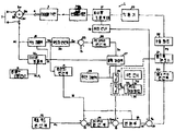
제 1 도는 본 발명의 일실시예를 표시하는 블록도.1 is a block diagram showing an embodiment of the invention.
제 2(a)도 내지 제 2(g)도는 제 1 도에 표시한 장치의 작동을 설명하기 위한 타임차아트.2 (a) to 2 (g) are time difference art for explaining the operation of the apparatus shown in FIG.
제 3 도는 제 1 도의 속도검출부의 상세블록도.3 is a detailed block diagram of the speed detector of FIG.
제 4 도는 마이크로컴퓨우터를 사용하여 구성한 본 발명의 다른 실시예를 표시하는 블록도.4 is a block diagram showing another embodiment of the present invention constructed using a microcomputer.
제 5 도는 제 4 도에 표시한 장치의 마이크로컴퓨우터에서 실행되는 제어프로그램의 플로우차아트.5 is a flowchart art of a control program executed in the microcomputer of the apparatus shown in FIG.
제 6 도는 제 5 도에 표시한 플로우차아트의 일부의 상세플로우차아트.6 is a detailed flowchart of a part of the flowchart art shown in FIG.
* 도면의 주요부분에 대한 부호의 설명* Explanation of symbols for main parts of the drawings
1,40 : 아이들 운전제어장치 2 : 연료분사펌프1,40: idle driving control device 2: fuel injection pump
3 : 디이젤기관 4 : 크랭크축3: diesel engine 4: crankshaft
7 : 회전센서 8 : 속도검출부7: rotation sensor 8: speed detector
10 : 타이밍검출부 11 : 평균치연산부10: timing detection unit 11: average value calculation unit
12 : 목표속도연산부 17 : 분사량조절부재12: target speed calculation unit 17: injection amount adjusting member
23 : 작동기 24 : 속도차연산부23: actuator 24: speed difference calculation unit
27 : 출력제어부 30 : 각통제어해제부27: output control unit 30: each cylinder control release unit
31 : 스위치 32 : 수온센서31 switch 32 water temperature sensor
AC : 교류신호 D1: 식별데이터AC: AC signal D 1 : Identification data
Nin: 순시속도데이터 D0: 제어출력데이터N in : Instantaneous speed data D 0 : Control output data
Nt: 목표속도데이터![]()
![]()
본 발명은 내연기관용 아이들 운전제어장치에 관한 것이고, 더욱 특별하게 말하면 다기통내연기관의 각기통의 출력의 어긋나기가 작게 되도록 각 기통마다에 공급연료의 조절을 행하고 아이들운전을 안정하게 행할 수가 있게한 내연기관용 아이들 운전제어장치에 관한 것이다.The present invention relates to an idle operation control device for an internal combustion engine, and more particularly, to control the supply fuel in each cylinder so that the output of each cylinder of the multi-cylinder internal combustion engine is small, and to make the idle operation stable. An idle driving control device for an internal combustion engine.
종래의 다기통내연기관의 연료분사량의 제어는 연료분사량을 전기통 공통으로 일률적으로 제어하는 것이기 때문에 내연기관 및 또는 연료분사펌프의 제조공차등에 의하여 각기통의 출력이 균일하게 되지 않고 특히 아이들회전시에 내연기관의 안정성이 현저하게 손상되고, 배기가스중에 포함되는 유해성분의 양이 증대하여 기관에 진동이 생기는 외로 기관의 진동에 의하여 소음이 발생되는 등의 불편이 생기기 쉬웠었다.Since the conventional fuel injection amount control of the multi-cylinder internal combustion engine is to control the fuel injection amount uniformly, the output of each cylinder is not uniform due to the manufacturing tolerances of the internal combustion engine and / or the fuel injection pump. However, the internal combustion engine stability was remarkably impaired, and the amount of harmful components contained in the exhaust gas increased, causing vibration to the engine.
상술의 불편을 해소하기 위하여 내연기관의 각기통마다에 분사되는 연료의 제어를 행하는 소의 각통제어 방식의 장치가 여러개 제안되어 있다.In order to solve the above-mentioned inconvenience, several small square cylinder control apparatuses which control fuel injected into each cylinder of an internal combustion engine have been proposed.
이 종류의 장치로서 예를들면 기통수의 정수배의 샘플링에 의하여 내연기관의 평균회전속도를 구해서 목표치로 하고 각기통의 회전속도와 이 목표치와의 차부터 소위 학습방식에 의하여 각기통에 대한 연료분사량의 제어를 행하게 한장치가 개시되어 있다(특개소 58-176424호 공보, 특개소 58-214627호 공보 및 특개소 58-214631호 공보참조)As a device of this type, for example, the average rotational speed of an internal combustion engine is obtained by sampling an integer multiple of the number of cylinders, and a target value is obtained. A device that allows control of an object is disclosed (see Japanese Patent Application Laid-Open Nos. 58-176424, 58-214627, and 58-214631).
그러나, 상술의 종래장치는 어느것도 평균기관속도와 그때마다의 각통의 속도와의 차부터 다음회의 분사량을 예측하는 소의 학습제어방식이므로 마이크로컴퓨우터내에 있어서, 학습결과를 평가하는데 시간을 요하고, 제어의 응답성이 나쁘고 더우기 학습결과를 평가하기 위하여 복잡한 산법을 필요로 하므로 그 개발에 대한 공수를 필요로 한다는 문제점을 가지고 있다.However, since the above-described conventional apparatus is a small learning control method that predicts the next injection amount from the difference between the average engine speed and the speed of each cylinder, it takes time to evaluate the learning result in the microcomputer. The problem is that the responsiveness of the control is bad and furthermore, the complicated algorithm is required to evaluate the learning result, and thus the labor for the development is required.
본 발명의 목적은 제어결과를 평가하기 위한 복잡한 산법을 필요로 하지 않고 다기통내연기관의 각 기통간의 출력차에 따른 폐쇄루우프 제어에 의하여 그때마다의 운전조건하에 있어서, 아이들운전이 항상 안정하게 제어되고, 기관의 진동을 작게 억제할 수 있게한 내연기관용 아이들운전 제어장치를 제공하는데 있다.The object of the present invention is not to require complicated algorithms for evaluating the control results, and to control the idle operation at all times under the operating conditions by the closed loop control according to the output difference between the cylinders of the multi-cylinder internal combustion engine. In addition, the present invention provides an idle driving control device for an internal combustion engine that can suppress vibration of an engine small.
본 발명의 구성은 다기통 내연기관의 평균속도를 연산하는 제 1 연산수단과 소요의 목표아이들 회전속도를 표시하는 목표속도 데이터를 출력하는 수단과 상기 제 1 연산수단의 연산결과와 상기 목표속도데이터에 응답하여 상기 목표아이들 회전속도를 얻기위하여 상기 내연기관에 공급하여야 할 연료의 양에 관련한 제 1 제어데이터를 출력하는 수단과 이 제 1 데이터에 응답하여 아이들회전속도의 폐쇄루우프 제어가 행하여지도록 소요의 조속수단을 제어하는 제어수단과를 구비하여된 폐쇄루우프 제어계를 가진 내연기관용 아이들 운전제어장치에 있어서, 상기 내연기관의 각기통의 소정의 타이밍에 있어서의 순시속도를 순차 검출하는 검출수단과 이 검출수단부터 순차출력되는 검출결과에 응답하여 각기통에 대한 순시속도와 각기통에 대하여 각각 미리정해져 있는 기준의 기통에 대한 순시속도와의 차이분에 응한 차이데이터를 모든 기통에 대하여 순차반복하여 연산출력하는 수단과 내연기관의 각기통의 작동타이밍을 검출하는 타이밍검출수단과 상기 차이데이터에 응답하여 상기 차이데이터에 의하여 표시되는 차이분을 영으로 하기위하여 필요한 공급연료에 관련한 제 2 제어데이터를 연산출력하는 수단과 상기 내연기관의 냉각수온에 관련한 수온신호를 출력하는 수단과 상기 타이밍검출수단에 의한 검출결과에 의하여 상기 각기통에 대한 다음회의 연료조절행정이전의 소요의 타이밍에서 상기 제 2 데이터를 출력하는 출력제어수단과 상기 수온신호에 응답하여 상기 냉각수온이 소정치 이상으로 된 경우에만 이 출력제어수단부터의 상기 제 2 데이터를 상기 폐쇄루우프제어계에 공급하는 수단과를 구비한 점에 특징을 가진다.The configuration of the present invention includes a first calculating means for calculating an average speed of a multi-cylinder internal combustion engine, means for outputting target speed data indicating a target child rotational speed required, an operation result of the first calculating means, and the target speed data. Means for outputting first control data relating to the amount of fuel to be supplied to the internal combustion engine in order to obtain the target idle rotational speed in response to the closed loop control of the idle rotational speed in response to the first data. An idle operation control apparatus for an internal combustion engine having a closed loop control system provided with control means for controlling a governing means of the engine, comprising: detecting means for sequentially detecting an instantaneous speed at a predetermined timing of each cylinder of the internal combustion engine; For the instantaneous speed for each cylinder and for each cylinder in response to the detection results sequentially output from the detection means. Means for repeatedly calculating and outputting the difference data corresponding to the difference between the instantaneous speeds for each predetermined reference cylinders for all cylinders, timing detecting means for detecting the operation timing of each cylinder of the internal combustion engine, and the difference data Means for calculating and outputting second control data relating to the supply fuel necessary for zeroing the difference indicated by the difference data in response; means for outputting a water temperature signal relating to the cooling water temperature of the internal combustion engine and the timing detection Output control means for outputting the second data at a timing required before the next fuel control stroke for each cylinder according to the detection result by the means; Only supplying the second data from this output control means to the closed loop control system. Is characterized in that it has a means.
상술의 구성에 의하면 내연기관의 평균속도가 소망의 목표아이들 회전속도에 제어되는 피이드백 제어루우프중에 내연기관의 각기통의 순시속도가 동등하게 되도록 각기통에 대한 조절량 제어를 행하는 피이드백 제어루우프를 마련하였으므로 내연기관의 각 속도변동폭을 일정하게 할수가 있고 내연기관의 진동을 감소시킬 수가 있는 회로, 소음레벨이 내리고 아이들링회전속도를 내릴수가 있다. 따라서 아이들링 운전을 저연료비로 또한 안정하게 행할수가 있다.According to the above-described configuration, among the feedback control loops in which the average speed of the internal combustion engine is controlled to the desired target idle rotational speed, the feedback control loop for controlling the amount of adjustment for each cylinder is made such that the instantaneous speeds of the respective cylinders of the internal combustion engine are equal. Since it is possible to make each speed fluctuation range of internal combustion engine constant, circuit which can reduce vibration of internal combustion engine, noise level can be lowered and idling rotation speed can be reduced. Therefore, idling operation can be performed stably with low fuel cost.
또 기관의 냉각수온이 소정치 이하이고 각통에 있어서의 연료의 연소가 불안전으로 되기 쉬운 운전조건에 있어서는 제 2 제어데이터를 출력하는 것을 정지하고, 저온시에 있어서의 각통 제어를 중지하므로 저온시에 있어서의 안정한 아이들 운전제어가 실현된다.In operation conditions where the cooling water temperature of the engine is lower than or equal to a predetermined value and combustion of fuel in each cylinder is likely to be unstable, output of the second control data is stopped, and each cylinder control at low temperature is stopped. Stable idle operation control is realized.
즉 냉각수온이 낮으면 연료의 연소가 불안정이고 각 통제어의 전제조건인 각기통에 동일 경향의 주기적 변동이 나타나 있다는 조건이 충족되지 않으므로 이러한 경우에는 오히려 각 기통마다의 분사량 제어는 정지한 편이 좋기 때문이다.In other words, when the cooling water temperature is low, the condition that the combustion of fuel is unstable and the periodic fluctuations of the same tendency appear in each cylinder, which is a prerequisite for each control word, is better to stop the injection volume control in each cylinder. Because.
제 1 도에는 본 발명에 의한 내연기관용 아이들 운전제어장치를 디이젤기관의 아이들 운전제어에 적용한 경우의 일실시예가 블록도로 표시되어 있다. 아이들 운전제어장치(1)는 연료분사펌프(2)부터 연료의 분사공급을 받는 디이젤기관(3)의 아이들회전속도의 제어를 행하기 위한 장치이다.FIG. 1 is a block diagram showing an embodiment in which the idle driving control apparatus for an internal combustion engine according to the present invention is applied to idle driving control of a diesel engine. The idle
디이젤기관(3)의 크랭크축(4)에는 크랭크축(4)이 소정의 기준각도위치에 달한것을 검출하기 위하여 펄서(5)와 전자픽업코일(6)부터된 공지의 회전센서(7)가 설치되어 있다. 도시의 실시예에서는 디이젤기관(3)은 4사이클 4기통이고, 펄서(5)의 주연에 90°간격으로 형성된 코그(cog) (5a) 내지 (5d)중의 코그(5a) 및 (5c)가 디이젤기관(3)의 4개의 기통중의 2개의 기통의 각 피스톤이 상사점에 달하였을때에 전자픽업코일(6)에 대향하게 펄서(5)와 크랭크축(4)과의 사이의 상호 위치 관계가 정해져 있다.In the
제 2(a) 도는 디이젤기관(3)의 순시회전속도(N)가 표시되어 있고, 제 2(b) 도 에는 이때 회전센서(7)부터 얻어진 교류신호(AC)의 파형이 표시되어 있다. 교류신호( AC)는 각코그가 전자픽업코일(6)에 대향할때마다 그의 레벨이 정과부에 변동하여 한쌍의 정과부의 피이크를 생기게 하는 파형으로 되어 각 정과부의 피이크간의 영교차점의 시각 t1, t3, t5,…t17이 각각 디이젤기관(3)의 어느것의 실린더피스톤의 상사점 타이밍에 대응하고 있다.FIG. 2 (a) shows the instantaneous rotation speed N of the diesel engine 3, and FIG. 2 (b) shows the waveform of the AC signal AC obtained from the rotation sensor 7 at this time. AC signal (AC) is gakko each time he faces the electronic pick-up coil (6) to change the portion of his level Jung is a waveform for causing a pair of Jung peak negative viewing angle of zero crossings between the respective positive and negative peak t 1, t 3 , t 5 ,... t 17 corresponds to the top dead center timing of any of the cylinder pistons of the diesel engine 3, respectively.
시각 t2, t4,…는 크랭크축에서, 상사점부터 90°경과한 타이밍을 표시하고 있다. 한편, 순시회전속도(N)의 각 골짜기로 되어 있는 시각 t1, t3, t5,…t17이 각기통에 있어서의 폭발타이밍이고, 이 폭발에 의하여 기관속도(N)는 상승하고 시각 t2, t4,…t16에 있어서, 기관속도(N)는 저하하기 시작하여 각각 다음에 폭발하는 기통의 폭발행정의 전에서 기관속도(N)는 극소치로 된다. 디이젤기관(3)의 순시속도는 상술의 이유에 의하여 주기적으로 변동하고 그의 변동주기는 크랭크축(4)의![]()
![]()
또, 순시회전속도(N)의 각 골짜기는 엄밀히 말하면 각기통의 피스톤이 압축상사점의 때와 일치하지 않은 경우도 있지만 본 명세서에 있어서는 편의상 일치하는 것으로 하여 설명한다.In addition, although each valley of the instantaneous rotational speed N may be strictly speaking, the piston of each cylinder may not correspond with the time of compression top dead center, but it demonstrates as a convenience here in this specification.
여기서, 디이젤기관(3)의 4개의 기통을 각각 기통(C1),(C2),(C3),(C4)로 칭하고 이들의 기통(C1) 내지 (C4)가 각각 t1, t3, t5, t7에 있어서, 폭발행정에 들어가 이후 이 순서로 각 기통이 순차폭발행정에 들어가는 것으로 하여 이하의 설명을 행한다.Here, four cylinders of the diesel engine 3 are referred to as cylinders (C 1 ), (C 2 ), (C 3 ), and (C 4 ), respectively, and these cylinders (C 1 ) to (C 4 ) are respectively t. In 1 , t 3 , t 5 , and t 7 , the following explanation is given assuming that the cylinder enters the explosion stroke and then each cylinder enters the sequential explosion stroke in this order.
교류신호(AC)의 각 영교차점에 의하여 표시되는 타이밍이 어느기통의 어떠한 타이밍을 표시하는가를 검출하기 위하여 교류신호(AC)는 기통(C1)에 장착되어 있는 연료분사밸브의 침밸브인양 센서(9)부터의 침밸브인양 펄스신호(NLP1)가 기준 타이밍 신호로서 인가되어 있는 타이밍검출부(10)에 입력되어 있다.The AC signal AC is a needle valve lift sensor of the fuel injection valve mounted in the cylinder C 1 so as to detect which timing is indicated by each zero crossing point of the AC signal AC. The needle valve lifting pulse signal NLP 1 from (9) is input to the
침밸브인양 펄스신호(NLP1)는 제 2(c) 도에 표시되어 있는 바와같이 기통(C1)의 폭발타이밍인 t1, t9, t17,…의 직전에 출력된다. 타이밍검출부(10)는 교류신호(AC)의 정방향펄스에 응답하여 그의 입력펄스수를 계수하는 동시에 침밸브인양 펄스신호(NLP1)에 의하여 복귀되는 2진 계수기로서 구성되어 있고 그의 계수결과를 표시하는 2진데이터가 식별데이터(D1)로서 출력된다. 따라서 이 식별데이터(D1)에 의하여 교류신호(AC)중의 임의의 영교차점이 어느 기통의 어떠한 작동타이밍에 대응하고 있는가를 용이하게 식별할수가 있다.Needle valve lift pulse signal (NLP 1) is the 2 (c) of the explosion timing of the cylinder (C 1) as indicated in Fig t 1, t 9, t 17 , ... Is output just before. The
식별데이터(D1)는 후술하는 바와같이 하여 절환 제어되는 스위치(SW)를 거쳐서 끄집어 내어져 속도검출부(8)에 입력된다.The identification data D 1 is taken out via the switch SW controlled to be switched as described later and input to the
속도검출부(8)는 각기통에 있어서의 폭발타이밍후 크랭크축(4)이 90°회전하는데 요하는 시간 θ21, θ21,…θ41, θ12, θ22,…를 교류신호(AC)에 의하여 계측하기 위한 것으로서, 제 3 도에 그의 구체적인 회로가 표시되어 있다. 제 3 도를 참조하면 속도검출부(8)는 교류신호(AC)와 위상동기하고 있고 교류신호(AC)보다 충분히 주파수가 높은 계수펄스(CP)를 교류신호(AC)에 의하여 출력하는 펄스발생기(81)와 계수펄스(CP)의 펄스수를 계수하기 위한 계수기(82)와를 구비하고 있다. 계수기(82)는 계수펄스(CP)가 입력되어 있는 입력단자(82a) 이외로 계수기(82)의 계수내용을 복귀하여 계수동작을 출발시키기 위한 출발펄스를 주기위한 출발단자(82b)와 계수기(82)의 계수동작을 정지시켜 그의 계수내용을 유지해두기 위한 정지펄스를 주기위한 정지단자(82c)와를 구비하고 있다.
각단자(82b), (82c)에는 데코우터(83), (84)의 각 출력선(83a), (84a)이 접속되어 있고, 이들의 데코우터(83), (84)에는 식별데이터(D1)가 입력되어 있다.The output lines 83a and 84a of the decoders 83 and 84 are connected to the terminals 82b and 82c, respectively, and the identification data ( D 1 ) is input.
식별데이터(D1)는 이미 설명한 바와같이 침밸브인 양펄스신호(NLP1)에 의하여 복귀된 계수기에 의하여 교류신호(AC)중에 그후 생긴 정방향펄스의 수를 표시하는 것으로서, 도시의 실시예에서는 침밸브인양 펄스신호(NLP1)에 의하여 복귀되었을때에 식별데이터(D1)의 내용이 영이되게 타이밍검출부(10)가 구성되어 있다. 따라서 식별데이터(D1)의 내용은 제 2(d)도에 표시된 바와같이 t=t1에서 1이 되고, t2에서 2, t3에서 3으로 되고, 이와같이 하여 교류신호(AC)의 정방향펄스가 발생할때마다 하나씩 증가하여, t8에서 8이 된후 t9의 직전에 출력되는 침밸브인 양펄스신호(NLP1)에 의하여 0이 되고, 이후 동등하게 하여 그 내용이 변화한다.The identification data D 1 indicates the number of forward pulses generated after the AC signal AC by the counter returned by the positive pulse signal NLP 1 as the needle valve as described above. The
데코우터(83)는 식별데이터(D1)의 내용이 1,3,5,7의 어느것에 된것에 응답하여 그의 출력선(83a)의 레벨을 단시간만 「H」레벨로 하고 이것에 의하여 계수기(82)의 출발단자(82b)에 출발펄스를 공급한다. 한편, 데코우터(84)는 식별데이터(D1)의 내용이 2,4,6,8의 어느것에 된것에 응답하여 그의 출력선(84a)의 레벨을 단시간만 「H」레벨로 하고 이것에 의하여 계수기(82)의 정지단자(82c)에 정지펄스를 공급한다.The decorator 83 sets the level of the output line 83a to " H " only for a short time in response to the content of the identification data D 1 being any of 1 , 3, 5 and 7. The start pulse is supplied to the start terminal 82b of (82). On the other hand, the decorator 84 sets the level of the output line 84a to the "H" level only for a short time in response to the content of the identification data D 1 being either 2, 4, 6, or 8. By this, the stop pulse is supplied to the stop terminal 82c of the counter 82.
이결과, 계수기(82)는 각기통의 폭발타이밍(t1, t3, t5…)후 크랭크축(4)이 90°회전할때까지의 동안만 계수펄스(CP)의 계수를 행하는 것으로 된다. 따라서, 각시간 θ11, θ21,…θ41, θ12,…에 응한 계수데이터(CD)가 계수기(82)부터 출력된다.As a result, the counter 82 counts the counting pulses CP only until the
계수데이터(CD)는 또, 교류신호(AC)에 의하여 계측된 그때의 기관속도에 관련하는 데이터(ES)가 속도검출기(86)부터 입력되어 있는 변환회로(85)에 입력되어 있고, 여기에서 계수데이터(CD)는 데이터(ES)에 의하여 그때의 각시간 θ11, θ21…을 표시하는 데이터에 변환되고, 이 데이터는 각기통의 폭발직후의 기관의 순시기관속도를 표시하는 순시데이터로서 순차출력된다.In the coefficient data CD, data ES related to the engine speed at that time measured by the AC signal AC is input to the conversion circuit 85 inputted from the speed detector 86. The count data CD is obtained by the data ES at each time θ 11 , θ 21 . The data is converted into data indicating that the data is sequentially output as instantaneous data indicating the instantaneous engine speed of the engine immediately after the explosion of each cylinder.
상술과 같이하여 각기통의 폭발타이밍을 표시하는 교류신호(AC)의 영교차점타이밍부터 다음의 영교차점 타이밍까지의 시간 θ11, θ21,…을 표시하는 데이터가 속도검출부(8)부터 얻어지지만, 이후 본 명세서에 있어서는 기통(C1)에 대한 순시회전속도를 표시하는 순시속도데이터를 속도검출부(8)에 있어서 검출된 순서에 따라 일반적으로 Nin(n=1,2,…)로 표시하는 것으로 한다.As described above, the time from the zero crossing timing of the AC signal indicating the explosion timing of each cylinder to the next zero crossing timing θ 11 , θ 21 ,... Although the data indicating is obtained from the
따라서, 속도검출부(8)부터 출력되는 순시속도데이터(Nin)의 내용은 제 2(e)도에 표시한 바와같이 된다.Therefore, the contents of the instantaneous speed data N in output from the
순시속도데이터(Nin)는 평균치연산부(11)에 입력되고 여기에서 디이젤기관(3)의 평균속도가 연산된다. 부호(12)에서 표시되는 것은 디이젤기관(3)의 그때마다의 운전상태에 대응하는 목표아이들 회전속도를 연산하고, 그 연산결과를 표시하는 목표속도데이터(Nt)를 출력하는 목표속도연산부이다.Instantaneous speed data N in is input to the average value calculating part 11, and the average speed of the diesel engine 3 is computed here. Displayed by the code | symbol 12 is a target speed calculating part which calculates the target idle rotational speed corresponding to the operation state of the diesel engine 3 at every time, and outputs target speed data N t which displays the calculation result. .
목표속도연산부(12)는 디이젤기관(3)의 소요의 운전파라미터에 따라 그때 마다의 운전상태에 응한 최적의 아이들회전속도를 표시하는 목표속도데이터(Nt)를 출력하는 공지의 구성이므로, 그의 상세한 구성을 도시하는 것을 생략한다.Since the target speed calculator 12 is a well-known configuration for outputting target speed data N t indicative of the optimum idle rotational speed in accordance with the driving conditions of the diesel engine 3 in accordance with the required driving parameters, The illustration of the detailed configuration is omitted.
평균치연산부(11)부터 출력되는 평균속도데이터(![]()
![]()
제1PID 연산부(14)에 있어서의 연산결과는 분사량의 차원의 데이터(Qide)로서 끄집어 내어져 가산부(15)를 거쳐서 평균속도데이터(![]()
![]()
가산기(19)부터의 가산출력신호는 제2PID 연산부(20)에 입력되고, PID 제어를 위한 신호처리가 시행된후, 펄스폭 변조기(21)에 입력되고, 제2PID 연산부(20)부터의 출력에 응한 충격계수(duty cycle)의 펄스신호(PS)가 출력된다. 펄스신호(PS)는 구동회로(22) 거쳐서 분사량조절부재(17)의 위치제어를 행하기 위한 작동기(23)에 인가되어 이것에 의하여 분사량 조절부재(17)에서는 디이젤기관(3)이 목표아이들회전속도에서 아이들 운전되도록 위치제어 된다.The addition output signal from the adder 19 is input to the second PID calculation section 20, and after signal processing for PID control is performed, it is input to the pulse width modulator 21 and output from the second PID calculation section 20. According to the duty cycle (duty cycle) pulse signal PS is output. The pulse signal PS is applied to the
평균기관속도 및 분사량 조절부재의 실제의 위치에 응답하는 상술의 폐쇄루우프 제어계에 의하여 디이젤기관(3)의 평균아이들회전속도를 소망의 목표아이들 회전속도에 일치시키기 위한 제어가 행하여 진다.The control for matching the average idle rotational speed of the diesel engine 3 to the desired target idle rotational speed is performed by the above closed loop control system in response to the actual engine speed and the actual position of the injection amount adjusting member.
본 장치(1)는 더우기, 디이젤기관(3)의 각기통의 출력을 동일하게 하도록 제어하는 소위 각통제어를 행하기 위한 별개의 폐쇄루우프제어계를 구비하고 있고, 다음에 이 폐쇄루우프제어계에 대하여 설명한다.Furthermore, the
각통제어를 위한 폐쇄루우프제어계는 각기통의 순시속도의 차가 영이되도록 각 기통에 공급되는 연료를 조절하기 위한 것으로서, 순시속도데이터(Nin)에 응답하여 기통(C1) 내지 (C4)의 각각에 대한 순시속도와 각 기통에 대하여 미리 정해져 있는 기준의 기통에 대한 기준순시속도와의 차이분을 연산하는 속도차연산부(24)를 구비하고 있다.The closed loop control system for control of each cylinder is for adjusting the fuel supplied to each cylinder so that the difference in instantaneous speed of each cylinder becomes zero, and in response to the instantaneous speed data (N in ) of the cylinders (C 1 ) to (C 4 ) The speed difference calculation part 24 which calculates the difference between the instantaneous speed for each and the reference instantaneous speed with respect to the reference cylinder predetermined for each cylinder is provided.
본 실시예에서는 착목한 기통에 대한 순시속도의 직전에 얻어진 순시속도가 기준의 순시속도로서 고교되고 따라서 N11-N21, N21-N31, N31-N41,…이 차이데이터(Dd)로서 속도차연산부(24)부터 순차 출력된다.In this embodiment, the instantaneous speed obtained immediately before the instantaneous speed with respect to the planted cylinder is high schooled as the reference instantaneous speed, and accordingly, N 11 -N 21 , N 21 -N 31 , N 31 -N 41 ,. The difference data D d is sequentially output from the speed difference calculating unit 24.
이들의 차이데이터의 출력타이밍이 제 2(f)도에 표시되어 있다. 각기통의 순시속도는 상호에 동일치인것이 바람직하고, 차이데이터(Dd)의 치는 영으로 되는 것이 소망된다. 따라서 차이데이터(Dd)는 영을 내용으로 하는 기준데이터(Dr)와, 가산부(25)에 있어서 도시의 극성으로 가산되고, 그 가산결과는 제3PID 연산부(26)에 있어서 제어를 위하여 필요한 처리가 시행된 후, 분사량의 차원을 가지는 제이데이터(D0)로서 출력된다.The output timing of these difference data is shown in FIG. 2 (f). The instantaneous speed of each cylinder is preferably equal to each other, and the value of the difference data D d is desired to be zero. Therefore, the difference data D d is added with reference data D r having zero as contents and the polarity of the illustration in the adder 25, and the addition result is controlled by the third PID calculator 26 for control. After the necessary processing is carried out, it is output as J-data D 0 having the dimension of the injection amount.
또, 디이젤기관(3)의 평균속도데이터(![]()
![]()
![]()
![]()
![]()
![]()
출력제어부(27)는 차이데이터(Dd)에 인한 제어출력데이터(D0)의 출력타이밍을 제어하기 위한 것으로서, 식별데이터(D1)에 따라서 그의 출력타이밍이 이하와 같이 제어된다.The
즉, 어느 타이밍에서 얻어진 제어출력데이터(D0)는 그의 제어데이터의 기본으로 되어 있는 차이데이터에 관련하는 기통(C1)와 (C1+1)중, 기통(C1+1)에 대한 다음의 연료조절동작의 제어를 위하여 출력되고, 그때의 제1PID 연산부(14)의 출력인 아이들제어량 데이터(Qide)와 가산부(15)에 있어서 가산된다.That is, the control output data obtained at any timing (D 0) is a cylinder that corresponds to the difference data that is the basis for its control data (C 1) and (C 1 +1) of the, for the cylinder (C 1 +1) It is output for the control of the next fuel adjustment operation, and is added in the idle control amount data Q ide , which is the output of the first PID calculation unit 14, and in the adder 15.
따라서, 예를들면 시간(t4)에 있어서 얻어진 차이데이터(Nd(=N11-N21)은 기통(C1)과 (C2)와의 사이의 순시속도차를 표시하는 것으로서 따라서 기통(C2)이 다음에 폭발행정에 들어가는 시각 t11보다 적어도 앞에이고 기통(C1)이 폭발하는 시각 t9보다 뒤의 타이밍에서 출력된다.Thus, for example, the difference data N d (= N 11 -N 21 ) obtained at time t 4 indicates the instantaneous speed difference between the cylinder C 1 and (C 2 ) and thus the cylinder ( C 2) this is at least in advance of the time t 11 enters the explosion stroke to the next cylinder (C 1) is output at the timing later than the time t 9 to explode.
따라서, 이 경우 (N11-N21)의 차이데이터에 기인하는 제어데이터(D0)는 평균속도데이터(![]()
![]()
상술의 출력제어부는 기통(C2)와 (C3)와의 사이의 출력차, 기통(C3)와 (C4)와의 사이의 출력차 및 기통(C4)와 (C1)와의 사이의 출력차를 각각 영으로 하게 기통(C1) 및 (C2)와의 사이의 출력차를 영으로 하는 경우의 동작과 동일한 제어를 행하고 이것에 의하여 각 기통에 공급하여야할 연료분사량이 각기통마다에 제어되고, 각기통의 출력이 동일하게 된다.The above-described output control unit output difference between the cylinder (C 2 ) and (C 3 ), output difference between the cylinder (C 3 ) and (C 4 ) and between the cylinder (C 4 ) and (C 1 ) The same control as in the case where the output difference between the cylinders C 1 and (C 2 ) is zero with the output difference being zero, respectively, is performed, whereby the amount of fuel injection to be supplied to each cylinder is determined for each cylinder. It is controlled and the output of each cylinder becomes the same.
출력제어부(27)의 출력측에는 루우프제어부(28)에 의하여 온·오프제어되는 스위치(29)가 설치되어 있고, 각통제어에서 안정하게 행할 수 있는 소정의 조건이 충족되어 있는 것을 루우프제어부(28)에 의하여 검출된 경우에만, 스위치(29)를 닫아서 각통제어를 행하고, 소정의 조건이 충족되지 않은 경우에는 스위치(29)를 열고, 각통제어를 중지하고, 각통제어에 의하여 아이들운전이 오히려 불안정하게 되는 것을 방지하도록 구성되어 있다.On the output side of the
즉, 상술의 각통제어에 의한 각속도 제어는 아이들회전속도가 소망의 목표치에 대하여 소정의 범위내에 들어가 있는 안정한 상태에서 행하는 것이 바람직하다. 이것은 분사계 및 내연기관의 분산이 주기적으로 규칙 바르게 나타나는 경우에 있어서 상술의각통제어가 잘 작동하기 때문이다. 따라서 가감속조작을 행하고 있는 경우, 혹은 제어계에 이상이 생기고 있는 경우에는 각통제어를 행하면 오히려 아이들 운전이 불안정하게 된다.That is, the angular velocity control by the angular cylinder control described above is preferably performed in a stable state in which the idle rotational speed is within a predetermined range with respect to a desired target value. This is because the aforementioned cylinder control works well in the case where the dispersion of the injection system and the internal combustion engine is regularly and regularly shown. Therefore, when the acceleration / deceleration operation is performed or when an error occurs in the control system, the idle operation becomes rather unstable when each cylinder control is performed.
따라서, 본 실시예에서는 ① 목표아이들회전속도와 실제의 아이들회전속도와의 차가 소정시간이상 연속하여 소정치 a1보다 크지 않을것, ② 가속페달의 압입량이 소정치 a2이하로 되어 있는 것의 제조건이 모두 만족된 경우에만 스위치(29)가 폐쇄되어, 각통제어를 위한 제어루우프가 구성된다.Therefore, in the present embodiment, 1) the difference between the target idle rotational speed and the actual idle rotational speed is not greater than the predetermined value a 1 continuously for a predetermined time or more, and ② the indentation amount of the accelerator pedal is less than or equal to the predetermined value a 2 . The switch 29 is closed only when all the conditions are satisfied, so that a control loop for each cylinder control is constructed.
한편, ⓐ 목표아이들회전속도와 실제의 아이들회전속도와의 차가 소정치 a3(![]()
![]()
![]()
![]()
또 상술의 실시예에서는 루우프제어부(28)에 의하여 스위치(29)가 폐쇄되는 동시에 펄스폭변조기(21)부터의 펄스신호(PS)의 주파수가 디이젤기관의 회전속도와 간섭관계가 아닌 소정의 주파수에 변경되어, 이것에 의하여 각통제어시에는 작동기(23)의 응답성의 향상을 도모하고 있다.In addition, in the above-described embodiment, the switch 29 is closed by the loop control unit 28, and the frequency of the pulse signal PS from the pulse width modulator 21 is not determined by the rotational speed of the diesel engine. In this way, the response of the
본 장치(1)는 나아가서 예컨데 냉한지등에서 기관을 시동한 직후에, 기관의 냉가수온이 주위온도와 같은 정도일 경우에, 기관의 아이들회전속도제어를 더욱 안정하게 할 수 있도록 기관의 냉가수온이 소정치에 이르기까지는 출력데이터(D0)에 의한 각통제어를 일시정지시키기 위한 각통제어해제부(30)를 구비하고 있다.Further, the
각통제어해제부(30)는 스위치(29)와 직렬로 배설된 스위치(31)와 디이젤기관(3)의 냉각수온을 나타낸 수온신호(Sw)를 출력하는 수온센서(32)와 수온신호(Sw)에 응답하여 냉각수온(Sw)이 소정치(Tr)인지 아닌지를 판별하여 Tw ![]()
![]()
![]()
![]()
이런 결과로, 냉각수온(Tw)이 미리 정하여진 값(Tr)보다 작을 경우에는 스위치(31)가 오프되며, 스위치(29)의 작동상태의 여하에 상관없이 출력데이터(D0)가 가산부(15)에 공급되는 것이 정지되어, 각통제어가 해제상태로 된다.As a result, when the cooling water temperature T w is smaller than the predetermined value T r , the switch 31 is turned off, and the output data D 0 is output regardless of the operating state of the switch 29. Supply to the adder 15 is stopped, and each cylinder control is released.
따라서, 기관의 온도가 낮아서 각기통에 있어서의 연료의 연소상태가 불안정하게 되며, 따라서 각기통의 출력이 불규칙하게 변동하고 있어서 각기통의 출력차의 변화패턴이 일정하지 않으므로 각통제어를 양호하게 하기 위한 전제조건이 충족되어 있지 않을 경우에 각통제어의 해제를 하게 된다. 이런 경우에는 기관의 평균속도데이터에 따라서 아이들회전속도가 필요로 하는 목표치가 되도록 제어될뿐 아니라, 상술한 상태에 있어서는 각통제어는 잘 작동하지 않아서 각통제어를 하지 않는 편이 아이들 회전속도의 제어를 안정하게 실행할 수 있게 된다.Therefore, the combustion temperature of the fuel in each cylinder becomes unstable due to the low engine temperature. Therefore, the output pattern of each cylinder is changed irregularly, so that the change pattern of the output difference of each cylinder is not constant. If the precondition is not satisfied, the control of each cylinder is released. In this case, not only the idle rotation speed is controlled according to the average speed data of the engine, but also the cylinder control does not operate well in the above-described state, so that the control of the idle rotation speed is more stable. Can be run.
기관의 냉각수온이 각기통에 있어서의 연료의 연소상태가 안정하게 실행할 수 있는 값(Tr)으로 까지 상승하였을 경우에, 스위치(31)는 온되며, 이런결과로 상술한 각통제어도 실행되고, 아이들회전속도제어를 극히 안정하게 하여, 연료소비률의 저감, 소음저감의 상태에서 디이젤기관(3)의 아이들운전을 할 수 있다.When the coolant temperature of the engine has risen to a value T r at which the combustion state of the fuel in each cylinder can be stably executed, the switch 31 is turned on, and as a result, the angle cylinder control described above is also executed. The idling speed control can be extremely stable, and the diesel engine 3 can be idled in a state of reducing fuel consumption and noise.
또 상기 실시예에서는 냉각수온에 따라서 개폐하는 스위치(31)를 스위치(29)와 별도로 마련한 경우에 대하여 설명하였지만 상기 설명부터 이해되는 바와같이 예를들면 스위치 제어회로(33)부터의 스위치제어신호(S3)를 루우프 제어부(28)에 입력하고 상술한 스위치(29)의 개폐조건중에 냉각수온(Tw)이 소정치(Tr) 이상으로 되어 있는가 아닌가의 조건을 넣도록 구성하여도 좋다.In the above embodiment, a case in which the switch 31 for opening and closing according to the cooling water temperature is provided separately from the switch 29 has been described. For example, as can be understood from the above description, for example, the switch control signal from the switch control circuit 33 ( S 3 ) may be input to the loop control unit 28 and a condition may be set in which the cooling water temperature T w is equal to or larger than the predetermined value T r during the opening and closing conditions of the switch 29 described above.
상술한 구성에 의하면 디이젤기관의 평균속도 및 분사량 조절부재의 위치에 따라서 폐루우프제어에 의하여 기관속도에 언더슈우트등의 과도적인 변화에 대한 제어 및 아이들회전속도를 목표치에 대략, 이르게 하는등의 제어가 실행되어 이에 따라, 아이들회전속도가 대체로 안정한 상태에서, 각통제어에 따라 각기통의 속도변동이 동일하게 되도록 제어를 하게 된다.According to the above-described configuration, according to the average speed of the diesel engine and the position of the injection amount adjusting member, the control of the transient changes such as the undershoot and the idle speed by the closed loop control and the idle rotational speed are approximately reached to the target value. The control is executed to thereby control the speed fluctuations of the respective cylinders in accordance with the respective cylinder control while the idle rotational speed is substantially stable.
각통제어가 실행되고 있을 경우에도, 평균속도의 제어는 실행되고 있으며, 출력량의 태반을 맏아가지고 있어 각통제어는 그것을 보정하는 기능을 다하고 있다. 또 냉각수온도가 소정치 이하인 경우에는 각통제어를 해제하고 저온시에 각통제어를 행하는 것에 의하여 아이들회전속도의 제어가 오히려 불안정하게 되는 것을 방지하도록 하였으므로 내연기관의 아이들운전을 모든 조건하에 있어서, 안정하게 제어할 수 가 있다. 더우기 상술한 바와같이 각통제어는 아이들 회전속도가 목표치의 근방에 있을 경우에만 실행할 수 있는 구성으로 하였으나 이와같은 영역에서는 평균아이들 회전속도의 제어의 이득은 작게 설정되어 있으며, 각통제어의 동작에 커다란 영향을 줄수 없도록 되어 있다.Even when each cylinder control is being executed, control of the average speed is carried out, the placenta of the output quantity is born, and each cylinder control performs a function of correcting it. When the coolant temperature is lower than the predetermined value, the cylinder cylinder control is released and the cylinder cylinder control is prevented from being unstable by performing the cylinder cylinder control at low temperature. Therefore, the idle operation of the internal combustion engine is stably under all conditions. Can be controlled. Furthermore, as described above, the angle cylinder control can be executed only when the idle rotational speed is near the target value. However, in such a region, the gain of the control of the average children's rotational speed is set small, and it has a great influence on the operation of the angle cylinder control. It cannot be given.
또, 상기한 실시예에서는 각기통의 각속도를 검출하기 위하여 착안한 기통이 압축상사점에 이르러서부터 크랭크축이 90°회전까지 사이의 시간을 기본으로 하고 있으므로 폭발토오크의 변동을 잘 검출할 수 있어서 제어성능의 향상에 도움이 되고 있다.In addition, in the above embodiment, since the cylinder focused on detecting the angular velocity of each cylinder is based on the time between the compression top dead center and the crankshaft by 90 ° rotation, fluctuations in the explosion torque can be detected well. It helps to improve control performance.
제 4 도에는 아이들 운전제어장치를 마이크로컴퓨우터를 사용하여 실현하도록 한 본 발명의 다른 실시예를 나타내고 있다.4 shows another embodiment of the present invention in which an idle driving control device is realized by using a microcomputer.
제 4 도에 나타낸 아이들 운전제어장치(40)의 각부중에서 제11도에 나타낸 부분과 동일한 부분에는 동일한 부호를 부쳐서 그 설명을 생략하였다. (41)은 파형정형회로이며, 여기에서 교류신호(AC)의 정방향펄스에 상응하는 펄스가 출력되어 상사점펄스(TDC)로서 출력된다.The same reference numerals are given to the same parts as those shown in FIG. 11 among the parts of the idle driving control apparatus 40 shown in FIG. 4, and the description thereof is omitted. Reference numeral 41 denotes a waveform shaping circuit, in which a pulse corresponding to the forward pulse of the AC signal AC is output and output as a top dead center pulse TDC.
이 상사점펄스(TDC), 니이들밸브리프트센서(9)로부터의 니이들밸브리프트펄스신호(NLP1) 및 위치센서(18)로부터의 실제위치신호(S2)는 판독전용메모리(ROM)(42)를 구비하고 있는 마이크로컴퓨우터(43)에 입력되어 있다.The top dead center pulse TDC, the needle valve lift pulse signal NLP 1 from the needle valve lift sensor 9, and the actual position signal S 2 from the position sensor 18 are read only memory (ROM). It is input to the microcomputer 43 provided with 42.
ROM(42)내에는, 제 1 도에 나타낸 장치에 의하여 실행되는 아이들회전속도제어와 같은 기능을 수행하기 위한 제어프로그램이 기억되어 있으며, 이 제어프로그램이 마이크로컴퓨우터(43)에 의하여 실행하게 됨에 따라 필요로 하는 아이들회전속도제어를 하게 된다.In the
이 제어프로그램은 또 분사진각제어도 할 수 있도록 되어 있으며, 마이크로컴퓨우터(43)로부터는 분사량의 제어연산결과를 나타낸 제 1 출력신호(O1)와, 분사진각의 연산결과를 나타낸 제 2 출력신호(O2)가 출력되어 제 1 및 제 2 출력신호(O1), (O2)는 각기 펄스폭변조기(21) 및 타이머(37)에 공급되어 있다.The control program is also capable of controlling the angle of separation. The microcomputer 43 has a first output signal O 1 indicating the result of the control calculation of the injection amount and a result of the calculation of the angle of separation. 2 output signals O 2 are output so that the first and second output signals O 1 , O 2 are supplied to the pulse width modulator 21 and the timer 37, respectively.
제 5 도에서는 ROM(42)내에 기억되는 제어프로그램의 플로우차아트를 나타내고 있다. 제어프로그램은 프로그램의 개시후, 초기화를 실행하는 스텝(120)와 가속페달의 조작량에 대응한 목표분사량의 연산 및 분사량조절부재(17)의 위치제어를 하는 스텝 (121)등으로 형성하는 주제어프로그램(122)의 외에도 니이들밸브리프트펄스신호(NLP1)이 출력된것에 응답하여 실행하는 개입중단프로그램(INT1)와 상사점펄스(TDC)의 출력에 응답하여 실행되는 별도의 개입중단프로그램(INT2)와를 구비하고 있다. 개입중단프로그램(INT1)은, 스탭(123)에서 우선 소프트카운터(TDCTR)의 내용을 (8)에 세트하고, 이어서 플래그(TF)를 「0」로하여 그 실행을 종료한다.5 shows a flowchart art of the control program stored in the
이 플래그(TF)는 나중에 설명하는 개입중단프로그램(2)에서 분사량데이터(Q1)의 연산을 실행하거나 또는 연산되어 있는 분사량데이터(Q1)를 출력할 것인지를 결정하기 위한 플래그이다.This flag TF is a flag for determining whether to execute the calculation of the injection amount data Q 1 or to output the calculated injection amount data Q 1 in the
개입중단프로그램(INT2)은, 상사점펄스(TDC)의 발생에 응답하여 실행되어 소프트카운터(TDCTR)의 내용을 1만큼 감소하고(스텝125), TDCTR=0인지 아닌지의 판별을 스텝(126)에서 실행하게 된다.The interruption interrupt program INT 2 is executed in response to the occurrence of the top dead center pulse TDC to decrease the contents of the soft counter TDCTR by 1 (step 125), and determine whether TDCTR = 0 or not (step 125). ) Will be executed.
TDCTR=0인 경우에는 스텝(127)에 전진하여 소프트카운터(TDCTR)의 내용을 (8)에 세트한 다음, 스텝(128)에 전진하여 플래그(TF)의 반전을 한다. 스탭(126)의 판별결과가 NO인 경우에는 스텝(128)에 전진하여, 플래그(TF)의 반전을 하게 된다. 그런다음, 상사점펄스(TDC)의 발생간격에 따라서, 서로 이웃하는 펄스사이의 시간간격을 나타낸 데이터(M1), (M2)…(제 5 도에 나타낸 시간 (T11), (T21), (T12),…를 나타낸다)를 연산하고, 이 연산결과에 따라서, 기관의 회전속도를 연산하게 된다(스텝(129)).If TDCTR = 0, it advances to step 127, sets the content of the soft counter TDCTR to (8), and then advances to step 128 to invert the flag TF. If the determination result of the staff 126 is NO, it advances to step 128, and the flag TF is reversed. Then, according to the interval of occurrence of the top dead center pulse (TDC), the data M 1 , M 2 ... (Times T 11 , T 21 , T 12 ,... Shown in FIG. 5) are calculated, and the rotational speed of the engine is calculated according to the calculation result (step 129). .
다음에 스텝(130)에서 니이들밸브리프로센서(9)가 고장인지 아닌지의 판별을 하게 된다. 이 판별을 카운터(TDCTR)의 내용이 (8)보다도 크고 또한 연료분사중임이 검출되었을 경우에 고장(NG)이라고 판별하게 된다.Next, in step 130, it is determined whether the needle valve repro sensor 9 is broken or not. This determination is judged to be a failure NG when the contents of the counter TDCTR are larger than (8) and it is detected that fuel injection is in progress.
니이들밸브리프트센서(9)가 고장이 아니었으면 스텝(131)-(133)에서 기관의 냉각수온(Tw)이 소정치(Tr) 이상으로 되어 있는지 아닌지, 가속페달의 힘껏 밟는량(0)이 소정치(a2) 이하로 되어 있는지 아닌지, 목표아이들회전속도(Nt)와 평균아이들 회전속도(![]()
![]()
![]()
![]()
TDC의 발생에 응답하여 소프트카운터(TDCTR)의 내용을 1만큼 감소하여 (스텝(125)), 플래그(TF)의 반전을 한 (스텝(126))다음, 상사점펄스(TDC)…을 연산하게 된다.In response to the occurrence of the TDC, the content of the soft counter TDCTR is decreased by 1 (step 125), the flag TF is inverted (step 126), and then the top dead center pulse TDC... Will be calculated.
다음에 스텝(128)에서 니이들밸브리프트센서(9)가 고장인지 아닌지의 판별을 하게 된다.Next, in step 128, it is determined whether the needle valve lift sensor 9 is broken or not.
이 판별은 카운터(TDCTR)의 내용이 (8)보다 크고 또한 연료가 분사중임을 검출하였을 경우에 고장(NG)이라고 판별하게 된다. 니이들밸브리프트센서(9)가 고장이 아니었으면, 스텝(129)에 전진하여 기관의 냉각수온(Tw)이 소정치(Tr) 이상으로 되어 있는지 아닌지의 판별을 하고 Tw ![]()
![]()
한편 스텝(131)-(133)중의 적어도 하나에 있어서의 판별결과가 NO인 경우에는 스텝(132)에서의 각통제어연산은 실행되지 않으며, 평균기관속도에 의한 아이들회전제어만이 실행된다.On the other hand, when the discrimination result in at least one of the steps 131 to 133 is NO, the angular cylinder control calculation in step 132 is not executed, and only the idle rotation control by the average engine speed is executed.
더우기, 냉각수온이 낮을 경우에는 연소가 불안정하기 때문에 그 폭발이 같은 경향을 나타내지 않아서 출력토오크의 크기가 불안정하게 되고 각통제어의 전제가 되는 각통 하나 하나에 발생하는 연소의 동일경향의 주기적 변동을 보증할 수 없다.Moreover, when the cooling water temperature is low, since the combustion is unstable, the explosion does not show the same tendency, so the output torque becomes unstable and guarantees periodic fluctuations in the same tendency of combustion occurring in each cylinder which is the premise of each cylinder control. Can not.
이와같이 냉각수온의 상태는 각통제어를 하는 경우의 전제조건을 판별하기 위한 요소의 하나로서 생각할 수 있는 것이며, 따라서 Tw ![]()
![]()
스텝(138)에서는 서로 이웃하는 상사점펄스(TDC)의 시간간격을 나타낸 데이터중에서 현재의 개입중단프로그램(INT2)의 실행에서 얻은 데이터(Mn)와 1회전의 개입중단프로그램(INT2)의 실행시에 얻은 데이터(Nn-1)와의 대소비교를 하게 된다.Step 138. In another current interrupt program from neighboring data showing the time interval of the top dead center pulse (TDC) of the data obtained in the execution of the (INT 2) (M n) and interrupt the first rotation program (INT 2) The comparison with the data (N n-1 ) obtained at the time of execution is performed.
제 2(a)도, 제 2(b)도로부터 용이하게 추측되는 바와같이 상사점펄스(TDC)의 펄스의 간격은 긴상태와 짧은상태가 번갈아 반복하여 생기므로 데이터(Mn)와 (Nn-1)의 비교에 따라 각 기통의 작동타이밍이 그 어느상태에 있는지를 판별할 수 있다.As can be easily estimated from the second (a) and second (b), the pulse interval of the top dead center pulse (TDC) is generated by alternating between the long state and the short state, so that the data M n and (N By comparing n-1 ), it is possible to determine which state the operation timing of each cylinder is in.
만약 Mn<Nn-1이면, 이번회의개입중단프로그램(INT2)의 실행을 하게한 상사점펄스(TDC)에 대응하는 기통이 폭발행정의 중간에 도달한 타이밍(제 2 도에서 t2, t4, t6,…에 상응하는 타이밍)을 나타낸 펄스로 된다. 한편, Mn>Nn-1이면, 어느한 기통이 폭발행정으로 들어가기 직전에 그 실린더피스톤이 상사점에 도달한 타이밍(제 2 도에서 t1, t3, t5,…에 상응하는 타이밍)을 나타낸 펄스로 된다.If M n <N n-1 , the timing at which the cylinder corresponding to the top dead center pulse (TDC) which caused the interruption interruption program (INT 2 ) to reach the middle of the explosion stroke (t 2 in FIG. 2). , timing corresponding to t 4 , t 6 ,... On the other hand, if M n > N n-1 , the timing at which the cylinder piston reaches top dead center immediately before any cylinder enters the explosion stroke (the timing corresponding to t 1 , t 3 , t 5 ,... In FIG. 2). ) Pulses.
따라서, 스텝(138)의 판별결과가 NO인 경우에는 각통제어연산은 실행하지 않고, 스텝(135)에 전진하여 플래그(FN)가 「1」인지 아닌지를 판별하게 된다. 플래그(FN)는 스텝(137)의 판별결과가 YES로 된일이 한번이라도 있는지 없는지를 판별하기 위하여 마련한 것이며, (FN)이 「0」인 경우에는, 스텝(139)의 판별결과는 NO로 되어, 스텝(140)에서 FN=「1」로 됨과 동시에 변수 N의 내용이 카운터(TDCTR)의 내용으로 되어 스텝(135)에 전진한다. 따라서 다음회 부터는 스텝(139)의 판별결과는 YES로 되어 스텝(141)에 전진하게 된다. 스텝(141)에서는 K=K+1으로 되어 K=4인지 아닌지의 판별을 스텝(142)에서 하게 0된다.Therefore, when the determination result of step 138 is NO, each cylinder control operation is not performed, but it advances to step 135, and it is discriminated whether or not the flag FN is "1". The flag FN is provided to discriminate whether or not the determination result of step 137 is YES even once. If (FN) is "0", the determination result of step 139 becomes NO. In step 140, FN = " 1 " and the content of variable N becomes the content of the counter TDCTR and advances to step 135. FIG. Therefore, the determination result of step 139 becomes YES from next time, and it advances to step 141. FIG. In step 141, K = K + 1, and 0 is made in step 142 to determine whether or not K = 4.
K는 어느한 기통이 폭발행정으로 될때마다 1만큼 커진다. 스텝(142)의 판별결과가 NO이면, 스텝(135)에 전진한다. 스텝(142)의 판별결과가 YES이면 스텝(144)에 전진하여 변수 N의 값이 카운터(TDCTR)의 값과 일치하고 있는지 아닌지의 판별을 하게되어 1 사이클경과 (크랭크축이 728회전)하고 있어 N=TDCTR인 경우에는, 스텝(145)에 전진하고, FATC=「1」, TDCTR=8 TF=「0」로 한 다음, 스텝(135)에 전진한다. 스텝 (144)의 판별결과 NO인 경우에는, 스텝(143)에 전진하여 K=「0」, FN=「0」로 되어 스텝(135)에 전진한다.K is increased by 1 each time a cylinder is exploded. If the determination result of step 142 is NO, it advances to step 135. If the determination result of step 142 is YES, it advances to step 144, and it is judged whether the value of the variable N matches the value of the counter (TDCTR), and it has passed about 1 cycle (crankshaft 728 revolutions). In the case of N = TDCTR, it advances to step 145, makes FATC = '1', makes TDCTR = 8 TF = '0', and then advances to step 135. If the determination result of step 144 is NO, it advances to step 143, and advances to step 135 with K = "0" and FN = "0".
이와같이 니이들밸브리프트센서(9)가 고장이 아니라고 판별되었을 경우에는 즉시 스텝(131)에 전진하지만, 니이들밸브리프트센서(9)가 고장났을 경우에는 데이터 Mn와 Mn-1와의 대소의 비교를 함에 따라 그때 그때의 있어서 기관의 각기통의 작동타이밍의 판별을 하게 되고, 이 판별결과에 따라서 각통제어연산의 스텝(134)을 실행하게 된다.In this way, when it is determined that the needle valve lift sensor 9 is not a malfunction, it advances immediately to step 131. However, when the needle valve lift sensor 9 is broken, the magnitude of the data M n and M n-1 is small. As a result of the comparison, the operation timing of each cylinder of the engine is discriminated at that time, and the
다음에, 스텝(134)에 나타낸 각통제어연산에 대하여 제 8도의 상세한 플로우차아트를 참조하여 설명한다.Next, the angle control operation shown in
우선, 스텝(150)에서 플래그(TF)의 판별을 하이 플래그(TF)가 「0」으로 되어 있을 경우에는 각통제어를 위한 제어데이터의 연산을 위한 스텝은 나중에 실행되며, 한편으로 플래그(TF)가 「1」로 되어 있을 경우에는, 각통제어를 위한 제어데이터를 출력하기 위한 스텝은 나중에 실행하게 된다.First, when the flag TF is determined in step 150 and the high flag TF is " 0 ", the step for calculating the control data for each barrel control is executed later, while the flag TF Is " 1 ", the step for outputting control data for each cylinder control is executed later.
플래그(TF)가 「0」인 경우라 함은 니이들밸브리프트펄스신호(NLP1)가 출력되어서부터 상사점펄스(TDC)가 아직 출력되어 있지 않은 상태 또는 니이들밸브리프트펄스신호(NLP1)가 출력되고 나서 짝수개의 상사점펄스(TDC)가 출력되어 있으며 그 다음의 상사점펄스(TDC)가 아직 출력되어 있지 않은 상태이다.The case where the flag TF is "0" means that the top dead center pulse TDC has not yet been output since the needle valve lift pulse signal NLP 1 is output or the needle valve lift pulse signal NLP 1. After outputting), an even number of top dead center pulses (TDC) are output, and the next top dead center pulse (TDC) is not yet output.
즉, 각기통이 어느것이나 폭발행정에 있지 않는 기간이며, 제 2 도에서 t2-t3, t4-t5, t6-t7, …의 각기간에 상응하고 있다. 한편, 플래그(TF)가 「1」인 경우라함은 상기 설명으로부터 아는 바와같이 어느 한 기통이 폭발행정에 있는 기간이며, 제 2 도에서 t1-t2, t3-t4, t5-t6, …의 각기간에 상응하고 있다. 플래그(TF)가 「0」인 경우에는 스텝(151)에서 그때의 기관의 운전조건이, 각통제어를 실행하는 필요조건을 충족하고 있는지 아닌지의 판별을 하여 그 판별결과가 NO로 되었을때에는 각통제어를 위한 각기통으로의 연료분제어량을 나타낸 데이터의 내용을 0으로 한다(스텝152).That is, it is a period in which none of the cylinders are in the explosive stroke, and in FIG. 2 , t 2 -t 3 , t 4 -t 5 , t 6 -t 7 ,. Corresponds to each period of. On the other hand, the case where the flag TF is "1" means a period in which one cylinder is in an explosive stroke, as seen from the above description, and in FIG. 2 , t 1 -t 2 , t 3 -t 4 , t 5- t 6 ,. Corresponds to each period of. If the flag TF is " 0 ", it is determined in step 151 whether the operating condition of the engine at that time satisfies the requirement for executing each cylinder control, and when the determination result is NO, each cylinder control The content of the data indicating the fuel fraction control amount to each cylinder is set to 0 (step 152).
본 명세서에서는 각통제어를 위한 분사량 제어데이터를 일반적으로 QAIN라고 표시한다.In the present specification, the injection amount control data for each cylinder control is generally denoted as Q AIN .
여기에서, i는 기통의 번호를 뜻하며, n은 이 데이터의 연산된 타이밍을 나타내고 있다. 이어서 스텝(163)에서 PID 제어를 위한 연산결과중에서 적분제어를 위한 적분제어데이터 IATC의 기억을 하게 된다. 이 PID 제어는 나중에 설명하는 스텝(159)에서 실행하게 되는 것으로 각통제어가 오프로 되기 직전에 스텝(159)에서 얻은 적분제어데이터가 마이크로컴퓨우터(43)의 RAM(44)내에 기억된다.Here, i denotes a cylinder number, and n denotes the calculated timing of this data. In step 163, the integral control data I ATC for the integral control is stored in the calculation result for the PID control. This PID control is executed in step 159 described later, and the integral control data obtained in step 159 is stored in the RAM 44 of the microcomputer 43 immediately before each cylinder control is turned off.
그런다음, 스텝(159)에서 평균속도에 기초한 아이들회전제어를 위한 분사량 제어데이터 Q1의 연산을 하게 되어, 스텝(154)에서, 이 제어데이터(Q1)에 1사이클전에 연산한 다음의 기통을 위한 분사량 제어데이터 QA(i+1)(n-1)을 가한 것을 제어데이터(Q1)로 한다. 이 제어데이터(Q1)는 마이크로컴퓨우터(43)의 RAM(44)내에 기억된다.Then, in step 159, calculation of the injection amount control data Q 1 for idle rotation control based on the average speed is performed. In step 154, the next cylinder computed one cycle before this control data Q 1 . and a control for the data (Q 1) was added to the injection amount control data Q a (i + 1) ( n-1). This control data Q 1 is stored in the RAM 44 of the microcomputer 43.
스텝(151)의 판별결과가 YES인 경우에는 스텝(155)에서 금회 출력된 상사점펄스(TDC)에 기초한 속도(Nin)와 하나앞에서 출력된 상사점펄스(TDC)에 기초하여 속도N(i-1)n와의 차분![]()
![]()
![]()
![]()
이것에 의하여 PID제어연산이 행하여져(스텝159), 그결과 얻어진 각통제어용의 제어데이터(QAIN)가 기억된다(스텝 160).By this, PID control operation is performed (step 159), and the control data Q AIN for each cylinder control obtained as a result is stored (step 160).
따라서 이 경우에는 스텝(160)에서 기억된 데이터의 값과 데이터(Q1)의 전회의 값이 가산되어 최초데이터(Q1)로 된다.In this case, therefore, the value of the data stored in step 160 and the previous value of the data Q 1 are added to become the initial data Q 1 .
스텝(150)의 판별결과가 YES로 되었을 경우에는 가속페달을 힘껏 밟는량에 따른 제어데이터(QAPP)의 값에 그때의 데이터(Q1)의 값을 가산하고 데이터(QPRV)로 하여 (스텝 161), 이것을 그때 흡입 행정에 있는 기통으로 분사량제어데이터로서 출력한다(스텝 162).When the determination result of step 150 is YES, the value of the data Q 1 at that time is added to the value of the control data Q APP according to the amount of stepping on the accelerator pedal, and the data Q PRV is defined as ( Step 161), this is output as injection quantity control data to the cylinder in a suction stroke at that time (step 162).
상기한 설명으로 알 수 있는 바와같이, 니이들밸브리프트센서(9)가 정상인 경우에는 플래그(TF)에 의하여 각통제어를 위한 제어데이터의 연산과 출력과를 제어하여 니이들밸브리프트센서(9)가 고장났을 경우에는, 데이터(Mn)와 (Mn-1)와의 비교에 따라 각통제어의 실행타이밍을 판별하고, 이에 따라서, 니이들밸브리프트센서(9)의 고장의 유무에 상관없이 각통제어를 할 수 있다.As can be seen from the above description, when the needle valve lift sensor 9 is normal, the needle valve lift sensor 9 is controlled by controlling the operation and output of the control data for each cylinder control by the flag TF. Is broken, the execution timing of each cylinder control is discriminated according to the comparison of the data M n and M n-1 , and accordingly, each cylinder is irrelevant whether or not the needle valve lift sensor 9 is broken. You can control it.
본 발명에 의하면 각기통의 각속도변동폭을 일정하게 하도록 각통제어를 행하므로 기관의 진동이 감소하고, 소음레벨이 내리고 나아가서는 아이들링회전속도를 내릴수가 있으므로 연료비의 개선에 기여하는 외로, 학습방식과 달리 연산처리가 용이하고, 구성이 간단하게 된다.According to the present invention, the angular velocity fluctuation range of each cylinder is controlled so that the vibration of the engine can be reduced, the noise level can be lowered, and the idling rotation speed can be lowered. Operation processing is easy and configuration is simplified.
또, 기관의 냉각수온에 응하여 각통제어의 해제를 행하고, 저온시에 있어서, 각통제어를 행하는 것에 의하여 오히려 제어의 안정성이 손상되는 것을 개선할 수가 있고 넓은 범위에 걸쳐서 아이들운전제어를 안정하게 행할수가 있다.In addition, by canceling each cylinder control in response to the cooling water temperature of the engine, and performing the cylinder control at low temperatures, it is possible to improve that the stability of the control is impaired, and the idling operation control can be stably performed over a wide range. have.
Claims (1)
Applications Claiming Priority (3)
| Application Number | Priority Date | Filing Date | Title |
|---|---|---|---|
| JP60047410A JPS61207853A (en) | 1985-03-12 | 1985-03-12 | Idle operation control device for internal-combustion engine |
| JP85-47410 | 1985-03-12 | ||
| JP47410 | 1985-03-12 |
Publications (2)
| Publication Number | Publication Date |
|---|---|
| KR860007462A KR860007462A (en) | 1986-10-13 |
| KR890004293B1 true KR890004293B1 (en) | 1989-10-30 |
Family
ID=12774354
Family Applications (1)
| Application Number | Title | Priority Date | Filing Date |
|---|---|---|---|
| KR1019860001781A KR890004293B1 (en) | 1985-03-12 | 1986-03-12 | Apparatus for controlling idling operation of an internal combustion engine |
Country Status (2)
| Country | Link |
|---|---|
| JP (1) | JPS61207853A (en) |
| KR (1) | KR890004293B1 (en) |
-
1985
- 1985-03-12 JP JP60047410A patent/JPS61207853A/en active Granted
-
1986
- 1986-03-12 KR KR1019860001781A patent/KR890004293B1/en not_active IP Right Cessation
Also Published As
| Publication number | Publication date |
|---|---|
| KR860007462A (en) | 1986-10-13 |
| JPH0467015B2 (en) | 1992-10-27 |
| JPS61207853A (en) | 1986-09-16 |
Similar Documents
| Publication | Publication Date | Title |
|---|---|---|
| US4780827A (en) | Apparatus for controlling idling operation of an internal combustion engine | |
| JP2556964B2 (en) | Idle operation control device for internal combustion engine | |
| US4381748A (en) | Method of regulating combustion in the combustion chambers of an internal combustion engine | |
| US4425890A (en) | Spark timing control apparatus for use with a internal combustion engine | |
| KR890004302B1 (en) | Apparatus of controlling idling operation for internal combustion engine | |
| JP2562577B2 (en) | Idle operation control device for internal combustion engine | |
| JP3331789B2 (en) | Ignition timing control device for internal combustion engine | |
| US4825833A (en) | Engine control apparatus | |
| US5003955A (en) | Method of controlling air-fuel ratio | |
| KR890004293B1 (en) | Apparatus for controlling idling operation of an internal combustion engine | |
| US4357828A (en) | Method of indicating a basic air-fuel ratio condition of an internal combustion engine | |
| KR890004301B1 (en) | Apparatus for controlling idling operation for an internal combustion engine | |
| KR890004294B1 (en) | Apparatus for controlling idling operation of an internal combustion engine | |
| KR890004295B1 (en) | Apparatus for controlling idling operation of an internal combustion engine | |
| US4442817A (en) | Electronically controlled fuel metering system | |
| KR890004292B1 (en) | Apparatus for controlling idling operation of an internal combustion engine | |
| KR930011044B1 (en) | Idle operation controller for internal combustion engine | |
| JPH0842434A (en) | Ignition timing controller of internal combustion engine | |
| KR890002988B1 (en) | Driving control device for internal combustion | |
| JPS6166825A (en) | Acceleration judging device of internal-combustion engine | |
| JPS5862329A (en) | Fuel injection device for internal-combustion engine | |
| JPS62240444A (en) | Device for controlling interruptingly increasing quantity at the time of accelerating electronically controlled fuel injection type internal combustion engine | |
| JPS62153543A (en) | Air-fuel ratio controller for internal combustion engine | |
| JPH03204730A (en) | Arithmetic unit | |
| JPS61244851A (en) | Idle operation controller for internal-combustion engine |
Legal Events
| Date | Code | Title | Description |
|---|---|---|---|
| A201 | Request for examination | ||
| G160 | Decision to publish patent application | ||
| E701 | Decision to grant or registration of patent right | ||
| GRNT | Written decision to grant | ||
| FPAY | Annual fee payment |
Payment date: 19981008 Year of fee payment: 10 |
|
| LAPS | Lapse due to unpaid annual fee |