KR890003025B1 - Quick connect fitting - Google Patents
Quick connect fitting Download PDFInfo
- Publication number
- KR890003025B1 KR890003025B1 KR1019860002286A KR860002286A KR890003025B1 KR 890003025 B1 KR890003025 B1 KR 890003025B1 KR 1019860002286 A KR1019860002286 A KR 1019860002286A KR 860002286 A KR860002286 A KR 860002286A KR 890003025 B1 KR890003025 B1 KR 890003025B1
- Authority
- KR
- South Korea
- Prior art keywords
- tube
- recess
- sleeve
- piston
- spherical surface
- Prior art date
Links
Images


Classifications
-
- F—MECHANICAL ENGINEERING; LIGHTING; HEATING; WEAPONS; BLASTING
- F16—ENGINEERING ELEMENTS AND UNITS; GENERAL MEASURES FOR PRODUCING AND MAINTAINING EFFECTIVE FUNCTIONING OF MACHINES OR INSTALLATIONS; THERMAL INSULATION IN GENERAL
- F16L—PIPES; JOINTS OR FITTINGS FOR PIPES; SUPPORTS FOR PIPES, CABLES OR PROTECTIVE TUBING; MEANS FOR THERMAL INSULATION IN GENERAL
- F16L17/00—Joints with packing adapted to sealing by fluid pressure
-
- F—MECHANICAL ENGINEERING; LIGHTING; HEATING; WEAPONS; BLASTING
- F16—ENGINEERING ELEMENTS AND UNITS; GENERAL MEASURES FOR PRODUCING AND MAINTAINING EFFECTIVE FUNCTIONING OF MACHINES OR INSTALLATIONS; THERMAL INSULATION IN GENERAL
- F16L—PIPES; JOINTS OR FITTINGS FOR PIPES; SUPPORTS FOR PIPES, CABLES OR PROTECTIVE TUBING; MEANS FOR THERMAL INSULATION IN GENERAL
- F16L37/00—Couplings of the quick-acting type
- F16L37/08—Couplings of the quick-acting type in which the connection between abutting or axially overlapping ends is maintained by locking members
- F16L37/084—Couplings of the quick-acting type in which the connection between abutting or axially overlapping ends is maintained by locking members combined with automatic locking
- F16L37/092—Couplings of the quick-acting type in which the connection between abutting or axially overlapping ends is maintained by locking members combined with automatic locking by means of elements wedged between the pipe and the frusto-conical surface of the body of the connector
- F16L37/0927—Couplings of the quick-acting type in which the connection between abutting or axially overlapping ends is maintained by locking members combined with automatic locking by means of elements wedged between the pipe and the frusto-conical surface of the body of the connector the wedge element being axially displaceable for releasing the coupling
-
- F—MECHANICAL ENGINEERING; LIGHTING; HEATING; WEAPONS; BLASTING
- F16—ENGINEERING ELEMENTS AND UNITS; GENERAL MEASURES FOR PRODUCING AND MAINTAINING EFFECTIVE FUNCTIONING OF MACHINES OR INSTALLATIONS; THERMAL INSULATION IN GENERAL
- F16C—SHAFTS; FLEXIBLE SHAFTS; ELEMENTS OR CRANKSHAFT MECHANISMS; ROTARY BODIES OTHER THAN GEARING ELEMENTS; BEARINGS
- F16C17/00—Sliding-contact bearings for exclusively rotary movement
-
- F—MECHANICAL ENGINEERING; LIGHTING; HEATING; WEAPONS; BLASTING
- F16—ENGINEERING ELEMENTS AND UNITS; GENERAL MEASURES FOR PRODUCING AND MAINTAINING EFFECTIVE FUNCTIONING OF MACHINES OR INSTALLATIONS; THERMAL INSULATION IN GENERAL
- F16L—PIPES; JOINTS OR FITTINGS FOR PIPES; SUPPORTS FOR PIPES, CABLES OR PROTECTIVE TUBING; MEANS FOR THERMAL INSULATION IN GENERAL
- F16L37/00—Couplings of the quick-acting type
- F16L37/02—Couplings of the quick-acting type in which the connection is maintained only by friction of the parts being joined
- F16L37/04—Couplings of the quick-acting type in which the connection is maintained only by friction of the parts being joined with an elastic outer part pressing against an inner part by reason of its elasticity
-
- F—MECHANICAL ENGINEERING; LIGHTING; HEATING; WEAPONS; BLASTING
- F16—ENGINEERING ELEMENTS AND UNITS; GENERAL MEASURES FOR PRODUCING AND MAINTAINING EFFECTIVE FUNCTIONING OF MACHINES OR INSTALLATIONS; THERMAL INSULATION IN GENERAL
- F16L—PIPES; JOINTS OR FITTINGS FOR PIPES; SUPPORTS FOR PIPES, CABLES OR PROTECTIVE TUBING; MEANS FOR THERMAL INSULATION IN GENERAL
- F16L37/00—Couplings of the quick-acting type
- F16L37/50—Couplings of the quick-acting type adjustable; allowing movement of the parts joined
- F16L37/52—Universal joints, i.e. with a mechanical connection allowing angular movement or adjustment of the axes of the parts in any direction
-
- Y—GENERAL TAGGING OF NEW TECHNOLOGICAL DEVELOPMENTS; GENERAL TAGGING OF CROSS-SECTIONAL TECHNOLOGIES SPANNING OVER SEVERAL SECTIONS OF THE IPC; TECHNICAL SUBJECTS COVERED BY FORMER USPC CROSS-REFERENCE ART COLLECTIONS [XRACs] AND DIGESTS
- Y10—TECHNICAL SUBJECTS COVERED BY FORMER USPC
- Y10S—TECHNICAL SUBJECTS COVERED BY FORMER USPC CROSS-REFERENCE ART COLLECTIONS [XRACs] AND DIGESTS
- Y10S285/00—Pipe joints or couplings
- Y10S285/902—Canted ring
-
- Y—GENERAL TAGGING OF NEW TECHNOLOGICAL DEVELOPMENTS; GENERAL TAGGING OF CROSS-SECTIONAL TECHNOLOGIES SPANNING OVER SEVERAL SECTIONS OF THE IPC; TECHNICAL SUBJECTS COVERED BY FORMER USPC CROSS-REFERENCE ART COLLECTIONS [XRACs] AND DIGESTS
- Y10—TECHNICAL SUBJECTS COVERED BY FORMER USPC
- Y10S—TECHNICAL SUBJECTS COVERED BY FORMER USPC CROSS-REFERENCE ART COLLECTIONS [XRACs] AND DIGESTS
- Y10S285/00—Pipe joints or couplings
- Y10S285/921—Snap-fit
Abstract
Description
제1도는 접속기구와 튜브의 길이방향 단면도.1 is a longitudinal sectional view of a connecting device and a tube.
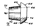
제2도는 접속기구의 고정용 슬리이브의 측면도.2 is a side view of the fixing sleeve of the connecting mechanism.
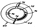
제3도는 고정용 슬리이브의 끝단면도.3 is an end view of the fixing sleeve.
제4조는 접속기구의 본체부의 측면도.Article 4 is a side view of the main body of the connecting mechanism.
제5도는 접속기구의 슬리이브 피스톤의 측면도.5 is a side view of the sleeve piston of the connecting mechanism.
제6도는 접속기구의 리테이너 캡의 측면도.6 is a side view of the retainer cap of the connecting mechanism.
제7도는 제6도의 리테이너 캡의 끝단면도.FIG. 7 is an end view of the retainer cap of FIG. 6. FIG.
제8도는 리테이너의 캡의 단면도.8 is a sectional view of the cap of the retainer.
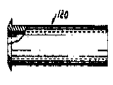
제9도는 연한 튜브용 앤빌 삽입구의 도면.9 is a view of anvil insert for a light tube.
* 도면의 주요부분에 대한 부호의 설명* Explanation of symbols for main parts of the drawings
20 : 접속기구본체 25, 27 : 오목부20: connecting
40 : 리테이너 캡 60 : 고정용 슬리이브40: retainer cap 60: fixing sleeve
64 : 구형표면 80 : 슬리이브 피스톤64: spherical surface 80: sleeve piston
90 : 경사진 오목부 100 : 리테이너 링90: inclined recess 100: retainer ring
12 : 튜브12: tube
본 발명은 튜브용 접속기구에 관한 것이며, 보다 더 상세히는 튜브의 끝을 나사가 난 접속기구 안으로 밀어넣어서 튜브가 빠지지 않도록 견고하게 유지시키고, 그리하여 공압 또는 유압시스템들에 유용한 적소에서의 튜브용 급속 접속을 용이하게 하는 접속기구에 관한 것이다.The present invention relates to a tube splice, and more particularly to the end of the tube being pushed into the threaded splice to keep the tube firmly secured so that it does not fall out, and thus rapid for tube in place useful for pneumatic or hydraulic systems. A connecting mechanism for facilitating connection is provided.
공작기계들, 자동차들과 기타 여러용도에 유압배관이 많이 이용된다.Hydraulic piping is widely used in machine tools, automobiles and many other applications.
많은 장치에서 배관을 신속하게 그리고 효과적으로 접속할 수 있다는 것은 바람직한 일이다. 접속을 행하기 위하여 렌치(wrench) 또는 다른 공구를 사용할 필요가 있을때엔, 많은 시간이 소요되고 견고한 이음은 숙련공이 기술을 가지고 조심스럽게 작업을 하지 않으면 이루어질 수 없다.In many devices it is desirable to be able to connect piping quickly and effectively. When it is necessary to use a wrench or other tool to make a connection, time consuming and rigid joints cannot be achieved unless the skilled worker has the skill and careful work.
조립라인들에서의 배관, 이를테면 자동차 전동장치, 냉각시스템 및 히이터용 배관의 설치에 있어서, 설치속도 및 품질은 필수적이다.In the installation of piping on assembly lines, such as automotive transmissions, cooling systems and piping for heaters, the installation speed and quality are essential.
1963년 9월 10일자 특허된 미합중국 특허 제 3,103,373호는 외부끝에서 경사진 원통형 오목부를 가진 접속기구를 개시하고 있다. 경사진 칼러(collar)가 그 경사진 끝안으로 삽입되고 또 다른 쐐기고리가 나사칼러의 회전에 의하여 가압될 때 그 경사진 칼러를 확장시킨다. 이렇게 접속하는 것을 확실히 하기 위해서는 부재들을 죄는 렌치를 이용할 필요가 있다.United States Patent No. 3,103,373, issued September 10, 1963, discloses a connection mechanism having a cylindrical recess inclined at its outer end. An inclined collar is inserted into the inclined end and when the another wedge is pressed by the rotation of the screw collar it expands the inclined collar. To ensure this connection, it is necessary to use a wrench that clamps the members.
1965년 4월 27일자 특허된 미합중국 특허 제 3,180,664호는 회전이음을 개시하고 있지만, 이 또한 압입이음(push-in joint)의 특성을 나타낼 수 있는 이음은 아니다. 나사가 난 리테이닝(retaining) 칼러는 이음을 완성하기 위해 죄어져야 한다.United States Patent No. 3,180,664, issued April 27, 1965, discloses a rotary joint, but this is also not a joint that can exhibit the characteristics of a push-in joint. Threaded retaining collars must be tightened to complete the seam.
그러나, 본 발명에 의하면, 렌치죄임이 필요없다.However, according to the present invention, there is no need for wrenching.
본 발명의 목적은 가요성 튜브가 안으로 삽입되어 그 이상의 손조작이 없이 유질될 수 있도록 접속기구(상세하게 설명됨)가 개방끝을 가지고 있는 바의 자동차 생산에 특히 사용하기 위한 압입식 튜브접속기구를 제공하는 것이다.An object of the present invention is a press-fit tube connection mechanism for use in automobile production, particularly in the production of bars in which the connection mechanism (described in detail) has an open end so that the flexible tube can be inserted in and oiled without further manipulation. To provide.
본 발명의 또 하나의 목적은 튜브의 끝이 안으로 삽입되어, 그것이 뒤로 물러나는 것에 대하여 즉시로 붙잡아서 누출이 되지 않도록 밀봉될 곳에 압입될 수 있는 접속기구조립체를 제공하는 것이다.It is a further object of the present invention to provide a connector assembly in which the end of the tube is inserted in and can be press-fitted in place to be sealed so that it immediately catches against retraction and does not leak.
본 발명의 또 다른 목적은 튜브의 회전과 제한된 각 운동을 밀봉이 방해됨이 없이 허용하는 튜브의 접속기구의 제공과 압력이 상승하면 더욱 단단하게 밀봉이 이루어질 수 있는 접속기구조립체를 제공하는 것이다.It is a further object of the present invention to provide a tube assembly that allows for rotation of the tube and limited angular movement without interruption of the seal and to provide a connector assembly that can be more tightly sealed as the pressure rises.
본 발명의 다른 또 하나의 목적은 튜브에 손상을 입히지 아니하고 부재들중의 하나를 적절히 조절함으로써 서로 풀릴수 있는 압입접속용 튜브접속기구를 제공하는 것이다.Another object of the present invention is to provide a press-fitting tube connecting mechanism which can be released from each other by appropriately adjusting one of the members without damaging the tube.
종래기술의 문제점을 극복하고 상기 목적들을 달성하기 위한, 본 발명에 따라서 튜브가 압입되어 고정되며 밀봉될 수 있는 바의 튜브용 급속접속기구는 (a)한쪽 끝에는 보통의 접속장치를 그리고 다른 한쪽 끝에는 개방적인 원통형 오목부를 가지고 있는 접속기구본체와, (b) 상기 오목부 안에서 상기 오목부에 대해서는 내부 밀봉을 그리고 삽입된 튜브에 대해서는 외부 밀봉을 이루고 있으며, 상기 원통형 오목부의 개방끝과 면하고 있는 내부 원추형 오목부를 가지고 있는 슬리이브 피스톤과, (c) 상기 오목부 안에서 상기 슬리이브 피스톤과의 축방향 정렬을 이루고 있고, 상기 슬리이브 피스톤의 상기 내부 원추형 오목부 안으로 관통하도록 배열된 외부 원추형 부분을 포함하고 있고, 상기 외부 원추형 부분과 대향하는 외부 구형표면에 대하여 상보적(相補的)으로 맞물릴 수 있는 내부 구형표면을 가지고서 상기 접속기구본체와 맞물릴 수 있는 리테이너 장치로 구성되어 있으며, 여기에서 상기 피스톤, 상기 고정용 슬리이브와 상기 내부 및 상기 외부 구형표면들은 상기 오목부와의 동축의 정렬로부터 상기 튜브의 제한된 편차를 위한 회전이음을 제공하도록 배열되고 치수맞춤되어 있다.In order to overcome the problems of the prior art and to achieve the above objects, the quick access mechanism for a tube of which the tube can be press-fitted, fixed and sealed according to the present invention comprises: A connecting body having an open cylindrical recess, and (b) an inner seal for the recess and an outer seal for the inserted tube, the inner facing the open end of the cylindrical recess. A sleeve piston having a conical recess; and (c) an outer conical portion in axial alignment with the sleeve piston in the recess and arranged to penetrate into the inner conical recess of the sleeve piston. And complementary to an outer spherical surface opposite the outer conical portion. And a retainer device having an inner spherical surface that can be engaged in engagement with the connecting mechanism main body, wherein the piston, the fixing sleeve and the inner and outer spherical surfaces are It is arranged and dimensioned to provide a rotary joint for limited deviation of the tube from coaxial alignment with the recess.
본 발명의 기타 목적들은 본 발명의 실시예 대하여 계획된 최선의 형태와 관련하여, 본원이 속한 기술분야에서 통상의 지식을 가진자에겐 상세하게 본 발명이 서로 기술되어 있는 다음의 상세한 설명 및 청구범위에서 명백하여질 것이다.Other objects of the present invention relate to the best mode contemplated for embodiments of the present invention, in the following detailed description and claims, which are described in detail by the present invention to those skilled in the art. Will be obvious.
도면을 참고하여 살펴보면, 제1도 및 제4도에서 조립된 6각형 외부표면 및 원통형 내부 오목부(27)를 가진 확대부분(26), 계단식 오목부(25), 어깨부분(24), 및 통로(23)를 구비하고서 외부나사가 난 목부분(22)를 포함하고 있는 접속기구본체(20)을 도시하고 있다. 어깨부분(28)은 오목부(25 및 27)들의 사이에서 9°의 경사를 갖도록 형성되어 있다. 원통형 연자부분(29)은 끝에 챔퍼(32 ; chamfer)를 가지고 있는 플랜지로서의 어깨부분(30)에서 확대된다. 이 본체(20)는 금속이나 고밀도 플라스틱(dense plastic)으로 이루어질 수 있다.Referring to the drawings, an enlarged portion 26, a stepped recess 25, a
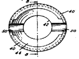
제1도 및 제6도 내지 제8도에서, 똑딱 단추식의 리테이너 캡(40)은 어깨부분(46)에서 최대 직경을 갖는 구형표면(44)을 개발하고 있는 튜브통로(42)를 가진 몸체부분을 포함하고 있다. 어깨부분(46)의 내경은 바깥쪽으로 벌어지는 경사트인구멍(48)을 이루고 있다. 직경방향으로 대향하는 노치(50 ; notch)들은 조립 및 분리시에 리테이너 캡의 외주의 가요성을 갖도록 해준다. 이러한 리테이너 캡(40)은 형상유지특성을 구비하고 있고 다만 똑딱 단추식 조립과 지레식 분리를 위하여 휘어지는 충분한 가용성을 구비하고 있는 플라스틱 재료로 바람직하게 성형된다.1 and 6 to 8, the snap button retainer cap 40 has a body with a
조립체의 제3부재는 제1도에 단면으로 나타나 있듯이 고정용 쐐기 및 밀봉마개로서의 고정용 슬리이브(60)이다. 그 측면도와 끝면도가 제2도 및 제3도에 각각 예시되어 있다. 이 고정용 슬리이브(60)는 한쪽 끝(66)에서 절단된 구형표면(64)를 가진 부분적이 구형부분(62)을 포함하고 있으며, 이는 보다 큰 직경부에서 그 부재의 축선에 대하여 가로지르는 평면에 어깨부분(68)을 형성하고 있다.The third member of the assembly is a fixing wedge and fixing sleeve 60 as a sealing plug, as shown in cross section in FIG. Side and end views thereof are illustrated in FIGS. 2 and 3, respectively. This fixing sleeve 60 comprises a partially spherical portion 62 with a spherical surface 64 cut at one end 66, which transverses with respect to the axis of the member at larger diameters. The
어깨부분(68)으로부터, 경사진 부분(70)은 축방향으로 연장되어 있다. 튜브통로(72)는 통로(74)에서 바깥쪽으로 약 2°각도로 경사지면서 부분(70)에 형성되어 있다. 경사진 연장부분(70)은 4개의 축방향 슬롯을 갖고 있어 이 부분이 기술되는 바와 같이 리테이너 튜브에서 조여지도록 한다. 이 고정용 슬리이브(60)는 또한 플라스틱으로 이루어질 수 있다.From the
조립체의 제4부재는 제1도에서 단면으로, 그리고 제5도에서 측면도로 도시된 슬리이브 피스톤(80)으로 불리는 플라스틱 성형부재이다. 이 부재는 2개의 절두 원추형 부분(82)들로 등을 맞대고 형성되어 있으며 ○링(112)용의 ○링홈(84)에 의하여 분리되어 있다. 원추들의 벽들은 이하에 설명되는 목적을 위하여 축선에 약 5°정도를 이루고 있다. 한쪽 끝에서 원통형 오목부(86)가 다른쪽 끝에서 끝나는 경사진 오목부(90)를 이루는 내측 끝의 어깨부분(88)에서 끝이나게 된다. 오목부(86)는 ○링(11)을 수용할 수 있도록 제공되며 경사진 오목부(90)는 고정용 슬리이브(60)의 경사진 부분(70)을 수용하고 보완하기 위하여 제공된다. 기능면에서 슬리이브 피스톤(80)은 관련된 경사진 부분에 의하여, 바깥쪽으로 캡에 의하여 움직임이 이루어지면 원주로 팽창될 수 있는 플라스틱 재료도 이루어진다.The fourth member of the assembly is a plastic molded member called
조립체의 제5부재는 제1도면에 단면이 도시된 폐쇄되고 금속으로 이루어진 리테이너 링(100)으로 구성된다. 이 링은 삽입된 튜브의 표면을 “붙잡아서(grab)”빠지는 것을 방지할 날카로운 모서리(104)를 갖는 밖으로 굽인 립(102 ; out-turned lip)을 갖고 있다.The fifth member of the assembly consists of a retainer ring 100 made of a closed metal, the cross section of which is shown in the first drawing. The ring has an out-turned lip 102 with sharp edges 104 that will prevent it from “grabing” the surface of the inserted tube.
이제 조립도인 제1도를 참고로 살펴보면, 부재(20, 40 ,60, 80 및 100)들은 모두 아래와 같이 미리 조립될 수 있다. ○링(110 및 112)들은 도시된 바와 같이 슬리이브 피스톤(80)에 미리 조립되고 리테이너 링(100) 및 슬리이브 피스톤(80)을 접속기구본체(20)의 오목부(27)안으로 이동시킨다. 구형으로 씌워진 고정용 슬리이브(60)의 경사진 부분(70)을 슬리이브 피스톤(80)의 경사진 오목부(90)안으로 삽입한다. 원한다면, 고정용 슬리이브(60)를 슬리이브 피스톤(80)안으로 미리 조립할 수 있다. 그런다음, 똑딱 단추식 리테이너 캡(40)의 경사트인구멍(48)이 접속기구본체(20)의 챔퍼(32)의 위로 캠의 운동이 이루어져서 어깨부분(30 및 46)들이 맞물려서 빠지는 것을 방지하도록 리테이너 캡(40)을 접속기구본체(20)의 위로 밀어준다. 전술된 바와 같은 부재들은 손으로 용이하게 조립될 수 있다.Referring now to FIG. 1, which is an assembly diagram, the
제1도에 도시된 바와같이, 조립된 부재들이 서로 이루어지면, 튜브(120)는 고정용 슬리이브(60)의 통로(72 및 74)들 안으로 그리고 슬리이브 피스톤(80)내 ○링(110)을 통하여 압입될 수 있다. 튜브는 ○링(110)과 맞붙게 되는 것을 방지하기 위하여 매끄러운 모서리를 갖도록 해야 한다. 그 다음에, 튜브는 리테이너링(100)의 구멍을 통하여 이송되어 어깨부분(24)에 의하여 더더욱 삽입되는 것이 방지될 것이다. 경사진 어깨부분(28)은 링(100)에 의하여 접하게 되고 이는 튜브가 삽입되는 중에 어떤면에서는 링을 개방시키려는 경향을 부여할 것이다. 임의의 형태로 튜브, 즉 금속, 플라스틱, 고무 등이 사용될 수 있으나, 삽입되는 끝은 그끝에 날카로운 모서리를 갖지 않아야 하고 적당하게 매끄러운 표면을 가지고 있어야 한다. 일단 튜부가 삽입되면,○링(110)에 의하여 밀봉되고 링(100)에 의하여 적절한 장서에서 고정된다. 삽입중에 링(100)은 전술한 바와 같이 경사진 어깨부분(28)에 인접될 수 있다. 튜브가 어느 정도 뒤로 물러나는 것은 링(100)을 슬리이브 피스톤(80)과 접촉상태에 이르게 하고 이때 튜브를 강제적으로 뒤로 당기면 슬리이브 피스톤은 고정용 슬리이브(60)의 경사진 부분(70)의 위로 밀려올가서 부재들을 죄고 상보적인 구형표면(44, 64)들을 단단히 접촉시키게 한다.As shown in FIG. 1, when the assembled members are made of one another, the
또한 공압 또는 유압이 슬리이브 피스톤에 가해져서 튜부가 뒤로 당겨지는 것과 같은 방식으로 그 부분을 탄탄하게 죌 것이다. 고정용 슬리이브(60)의 통로(74)에 약간 경사진 부분과 슬리이브 피스톤의 원추형 뿐만 아니라 구형표면들은 배관시에 그릇된 정렬에 의한 응력 및 진도의 흡수를 위하여 튜브를 어떤 방향으로나 5°정도 기울어질 수 있게 한다. 바꾸어 말하면, 한계를 갖는 제한된 정도까지 회전이음(swivel joint)이 있는 것이다. 또한 ○링시일(112)은 튜브가 각도에 따라 움직일 수 있고 또한 튜브가 관련된 부분과 함께 회전될 수 있는 견지에서 동적(動的)인 시일이다.In addition, pneumatic or hydraulic pressure will be applied to the sleeve piston to tighten the portion in the same way as the tubing is pulled back. The spherical surfaces as well as the slightly inclined portion of the passage 74 of the fixing sleeve 60 and the spherical surface of the sleeve piston are approximately 5 ° in any direction for absorption of stress and magnitude due to misalignment during piping. Allow it to tilt. In other words, there is a swivel joint to a limited extent with limits. In addition, the ring seal 112 is a dynamic seal in view of the fact that the tube can be moved with an angle and the tube can be rotated with the associated part.
따라서, 예를들어 공구가 필요없이 조립라인상에서 신속한 조립이 용이한 압입(push-in)식의 접속기구를 제공하게 되는 것이다. 장력이 튜브에 가해지거나 내압이 존재하게 되면, 눌림마개(슬리이브 피스톤(80), ○링(112) 및 부분(60))는 단단한 튜브상에서는 마찰파지력을 그리고 연한 튜브상에서는 압착을 일으키면서 피스톤의 주변을 밀착시킬 것이다. 어떤 당겨지는 것이나 압력은 고정용 슬리이브(60)로 하여금 구형표면(64)과 부분(60 및 80)들의 경사부분에 의하여 튜브주위를 조이게 해줄 것이다. 이러한 힘들은 또한 오목부(27)의 벽에 대향하여 ○-링(110)이 튜브에 대하여 보다 단단하게 힘이 가하여 질 것이다.Thus, for example, to provide a push-in connection mechanism that can be quickly assembled on the assembly line without the need for tools. When tension is applied to the tube or internal pressure is present, the push stopper (
연한 튜브가 사용되면, 제9도에 도시된 고정구 앤빌삽입구(stffener anvil insert)(120)는 접속기구 안으로 삽입되기전에 튜브의 끝에서 이용되게 된다.If a soft tube is used, the
링(100)은 튜브의 삽입전에는 조립체내에서 자유롭지만, 튜브가 링을 통과하여 멀어넣어지면 튜브끝은 링의 트인구멍안으로 들어가서 경사진 어깨부분으로 링을 후퇴 시킬 것이다.The ring 100 is free in the assembly prior to insertion of the tube, but if the tube is pulled away through the ring, the tube end will enter the open hole of the ring and retract the ring to the inclined shoulder.
튜브가 일단 삽입되면, 고정된 끝을 파괴하지 아니하고는 뺄 수가 없음을 알 수 있을 것이다. 그러나 똑딱단추식의 리테이너 캡(40)은 노치(50)에 대향하는 옆부분을 벌려서 분리시킬 수 있으므로 똑딱 단추식의 어깨부분(30, 46)들을 떼어서 분리시키 수 있다. 그 다음에 고정용 슬리이브(60)와 슬리이브 피스톤(80)이 떼어지고 리테이너 링(100)이 분리된다. 그 다음에 튜브는 새로운 리테이너 링을 설치하고 전술한 바와 같이 행함으로써 재사용 될 수 있다.Once the tube is inserted, it will be appreciated that it cannot be removed without breaking the fixed end. However, the snap button retainer cap 40 can be separated by opening the side opposite to the
상기 설명으로부터 확실한 바와 같이, 본 발명에 따른 튜브용 급속접속기구는 접속되는 튜브가 장력에 대하여 확실하게 유지되고 또한 접속기구와 튜브사이의 이음이 얼마간의 회전운동을 허용하는 우수한 작용효과를 나타낸다. 이러한 접속기구들은 연료배관과 히이터 호스 등의 자동차 배관에 사용되기 때문에, 일단 접속이 이루어지면 엔진으로부터의 연료의 누출 및 냉각유체의 손실을 피하도록 보장하는 것은 지극히 중요한 것이다.As is clear from the above description, the quick connection mechanism for a tube according to the present invention exhibits an excellent effect of ensuring that the tube to be connected is reliably held in tension and that the joint between the connection mechanism and the tube allows some rotational movement. Since these connections are used in automotive piping such as fuel piping and heater hoses, it is extremely important to ensure that once connected, leakage of fuel from the engine and loss of cooling fluid are avoided.
Claims (7)
Applications Claiming Priority (2)
| Application Number | Priority Date | Filing Date | Title |
|---|---|---|---|
| US06/718,563 US4664427A (en) | 1985-04-01 | 1985-04-01 | Quick connect fitting |
| US718,563 | 1985-04-01 |
Publications (2)
| Publication Number | Publication Date |
|---|---|
| KR860008404A KR860008404A (en) | 1986-11-15 |
| KR890003025B1 true KR890003025B1 (en) | 1989-08-18 |
Family
ID=24886550
Family Applications (1)
| Application Number | Title | Priority Date | Filing Date |
|---|---|---|---|
| KR1019860002286A KR890003025B1 (en) | 1985-04-01 | 1986-03-27 | Quick connect fitting |
Country Status (8)
| Country | Link |
|---|---|
| US (1) | US4664427A (en) |
| JP (1) | JPS61233290A (en) |
| KR (1) | KR890003025B1 (en) |
| CA (1) | CA1269119A (en) |
| DE (1) | DE3610085A1 (en) |
| FR (1) | FR2579716B1 (en) |
| GB (1) | GB2173271B (en) |
| IT (1) | IT1203760B (en) |
Families Citing this family (31)
| Publication number | Priority date | Publication date | Assignee | Title |
|---|---|---|---|---|
| DE3630494A1 (en) * | 1986-09-08 | 1988-03-10 | Volkswagen Ag | Plug-in coupling for a line, in particular a hose |
| US4993755A (en) * | 1989-09-22 | 1991-02-19 | Master Industries, Inc. | Quick connect fitting |
| US5087085A (en) * | 1990-10-17 | 1992-02-11 | General Components, Inc. | Sealing system for connecting beaded and flat coupling hardware |
| ES2081727B1 (en) * | 1991-07-26 | 1996-10-16 | Jimten Sa | IMPROVEMENTS IN TUBE JOINING SYSTEMS. |
| US5538297A (en) * | 1991-09-10 | 1996-07-23 | Bundy Corporation | Quick connect tubing connector |
| US6129391A (en) * | 1998-08-19 | 2000-10-10 | Dresser Industries, Inc. | Plastic coupling for plastic pipe having a completed installation signal |
| US6612622B2 (en) | 2000-04-06 | 2003-09-02 | Itt Manufacturing Enterprises, Inc. | Rotatable quick connector |
| US20030137148A1 (en) * | 2000-12-27 | 2003-07-24 | Andre Michael J. | Fluid quick connector with non-rotation conduit engaging ribs |
| US20030094767A1 (en) * | 2001-11-16 | 2003-05-22 | Alcatel | Mechanical seal for a cable installed in a corrugated duct |
| US20050140138A1 (en) * | 2003-10-31 | 2005-06-30 | Nordson Corporation | Locking hydraulic fitting for a dispensing apparatus |
| CN2782801Y (en) * | 2004-06-11 | 2006-05-24 | 松下电器产业株式会社 | Body cleaner |
| US7455330B2 (en) * | 2005-04-28 | 2008-11-25 | Kulm Holding Ag | Quick coupling |
| US7908730B2 (en) * | 2006-07-11 | 2011-03-22 | Haldex Brake Corporation | PTC fitting cartridge |
| US7730839B1 (en) | 2007-02-23 | 2010-06-08 | The United States Of America As Represented By The Secretary Of The Army | Interfacial stress reduction and load capacity enhancement system |
| EP2158935B1 (en) * | 2008-08-29 | 2014-07-16 | Dräger Medical GmbH | Connector for medicinal tubes |
| US20100283237A1 (en) * | 2009-01-24 | 2010-11-11 | Krohn Kenneth P | Device for connecting to ducts of various sizes and shapes |
| PT2213923E (en) * | 2009-01-30 | 2013-10-31 | Uponor Innovation Ab | Swivel joint |
| AU2010206066A1 (en) * | 2009-08-03 | 2011-02-17 | Gsa Industries (Aust.) Pty. Ltd. | Pipe coupling |
| US8764068B2 (en) | 2012-05-10 | 2014-07-01 | Moen Incorporated | Quick connect coupling with retention feature |
| NO337229B1 (en) | 2012-07-12 | 2016-02-15 | Ace Oil Tools As | Fixing device for a pipe body provided with one or more axially projecting functional elements adapted for use on a downhole pipe body, as well as a pipe string comprising several pipe bodies |
| US9523453B2 (en) | 2013-03-20 | 2016-12-20 | Miniature Precision Components, Inc. | Locking quick connect assembly |
| AU2014245848B2 (en) | 2013-03-26 | 2018-11-15 | Reliance Worldwide Corporation (Aust.) Pty. Ltd. | A tube coupling |
| US9447906B2 (en) | 2013-12-11 | 2016-09-20 | Nibco Inc. | Self-locking push-to-connect insert |
| US9541228B2 (en) * | 2013-12-11 | 2017-01-10 | Nibco Inc. | Push-to-connect fitting |
| US10006575B2 (en) | 2013-12-11 | 2018-06-26 | Nibco Inc. | Modular push-to-connect assembly |
| CN105917154B (en) | 2013-12-19 | 2018-06-22 | 诚信全球公司(澳大利亚)私人有限公司 | Pipe connects accessory |
| US9777875B2 (en) | 2014-02-26 | 2017-10-03 | Nibco Inc. | Clam shell push-to-connect assembly |
| DE102016101533A1 (en) * | 2016-01-28 | 2017-08-03 | Voss Automotive Gmbh | Coupling body for a plug connection of pipelines, in particular plastic pipelines |
| US10174874B2 (en) * | 2016-10-12 | 2019-01-08 | Honeywell International Inc | Pipe fitting with inner and outer seals |
| FR3092893B1 (en) | 2019-02-20 | 2021-08-27 | Avon Polymeres France | Articulated connection device of two tubular components. |
| CN117780298A (en) * | 2024-02-23 | 2024-03-29 | 太原理工大学 | Integrated hole sealing extraction device and method embedded with grouting channel and bag |
Family Cites Families (18)
| Publication number | Priority date | Publication date | Assignee | Title |
|---|---|---|---|---|
| US2413840A (en) * | 1944-05-24 | 1947-01-07 | Mercier Jean | Pipe coupling |
| AT164664B (en) * | 1946-01-29 | 1949-12-10 | Rudolf Bauer Pumpen U Armature | Pipe coupling for manure, irrigation u. Like plants |
| US2556659A (en) * | 1948-12-20 | 1951-06-12 | Charles E Patterson | Tube coupling |
| DE858049C (en) * | 1951-05-11 | 1952-12-04 | Hermann Wingerath Kommandit Ge | Pipe coupling |
| GB878602A (en) * | 1959-05-20 | 1961-10-04 | Bronzavia Sa | Flexible connection for pipes |
| GB912514A (en) * | 1960-08-17 | 1962-12-12 | Superflexit | Improvements in end fittings for flexible hoses, conduits or the like |
| DE1232415B (en) * | 1961-06-29 | 1967-01-12 | Crawford Fitting Co | Pipe connection |
| US3103373A (en) * | 1961-06-29 | 1963-09-10 | Crawford Fitting Co | Controlled phase sequential gripping device |
| US3180664A (en) * | 1961-07-20 | 1965-04-27 | Imp Eastman Corp | Ball pipe joint with composite ball member |
| US3738688A (en) * | 1971-05-10 | 1973-06-12 | Test Tools Inc | Quick mount fitting |
| US3951418A (en) * | 1974-01-21 | 1976-04-20 | W. S. Shamban & Co. | Moving captive seal construction usable under high temperature and cryogenic conditions |
| US4009720A (en) * | 1975-08-14 | 1977-03-01 | Shiley Laboratories, Inc. | Wedge seal for a tracheotomy tube |
| US4123090A (en) * | 1976-07-19 | 1978-10-31 | Imperial-Eastman Corporation | Push-pull fitting |
| FR2385024A2 (en) * | 1977-03-25 | 1978-10-20 | Parker Hannifin Rak Sa | Rapid-action coupling for plastics pipe - has hollow body with three internal steps and holder ring with gripper fingers |
| US4225162A (en) * | 1978-09-20 | 1980-09-30 | Amp Incorporated | Liquid tight connector |
| FR2479406B1 (en) * | 1980-03-28 | 1985-08-23 | Legris | INSTANT FITTINGS FOR BARE AND SMOOTH TUBES |
| US4601497A (en) * | 1980-10-29 | 1986-07-22 | Proprietary Technology | Swivelable quick connector assembly |
| US4522433A (en) * | 1982-05-14 | 1985-06-11 | Stanley Aviation Corporation | Spherical seat flexible O-ring coupling |
-
1985
- 1985-04-01 US US06/718,563 patent/US4664427A/en not_active Expired - Lifetime
-
1986
- 1986-03-14 CA CA000504098A patent/CA1269119A/en not_active Expired - Fee Related
- 1986-03-25 DE DE19863610085 patent/DE3610085A1/en active Granted
- 1986-03-26 GB GB8607457A patent/GB2173271B/en not_active Expired
- 1986-03-27 KR KR1019860002286A patent/KR890003025B1/en not_active IP Right Cessation
- 1986-03-28 FR FR868604545A patent/FR2579716B1/en not_active Expired
- 1986-03-28 IT IT47837/86A patent/IT1203760B/en active
- 1986-03-31 JP JP61071387A patent/JPS61233290A/en active Granted
Also Published As
| Publication number | Publication date |
|---|---|
| GB2173271A (en) | 1986-10-08 |
| FR2579716A1 (en) | 1986-10-03 |
| IT1203760B (en) | 1989-02-23 |
| IT8647837A0 (en) | 1986-03-28 |
| GB8607457D0 (en) | 1986-04-30 |
| KR860008404A (en) | 1986-11-15 |
| JPS61233290A (en) | 1986-10-17 |
| GB2173271B (en) | 1989-04-26 |
| DE3610085A1 (en) | 1986-10-09 |
| CA1269119A (en) | 1990-05-15 |
| US4664427A (en) | 1987-05-12 |
| DE3610085C2 (en) | 1991-04-11 |
| FR2579716B1 (en) | 1989-03-31 |
| JPH0158396B2 (en) | 1989-12-11 |
Similar Documents
| Publication | Publication Date | Title |
|---|---|---|
| KR890003025B1 (en) | Quick connect fitting | |
| US4070046A (en) | Pipe and tubing connecting sleeve | |
| US4993755A (en) | Quick connect fitting | |
| US5957509A (en) | Pipe coupling | |
| US4630848A (en) | Releasable coupling for tubes or pipes | |
| US3822074A (en) | Releasable coupling for tubular members and method for assemblying said coupling | |
| US5080405A (en) | Corrugated pipe coupling | |
| US5593186A (en) | Coupling for outer surface engagement of polymeric pipe | |
| KR910000565B1 (en) | Pipe joint | |
| US3113792A (en) | Pipe union with separable flange for nut | |
| US3685860A (en) | Hose coupling | |
| US6578879B2 (en) | Tube joint with connecting member and guide member configured to be prevented from disengagement | |
| CA2126276C (en) | Plumbing hookup kit | |
| US4082326A (en) | Compressible member for use in compression joint pipe connector | |
| US5048875A (en) | Connector interposed between small-diameter metallic pipe and flexible hose | |
| US4556242A (en) | Vibration resistant high pressure tube fitting | |
| US4413845A (en) | Pipe couplings | |
| US7997628B1 (en) | Mechanically restrained push-on pipe connection | |
| US5222772A (en) | Connector fittings and method of connecting same | |
| US6832791B2 (en) | Connection means for interconnecting two duct elements | |
| US4022499A (en) | Tube retaining compression fitting | |
| JP2005510665A (en) | Support sleeve for use in a pipe joint and joint housing for use with said sleeve | |
| US6402206B1 (en) | Fitting for plastic tubing | |
| US5911447A (en) | Pipe connector | |
| GB2177174A (en) | Improvements relating to pipe couplings and pipe joints formed therewith |
Legal Events
| Date | Code | Title | Description |
|---|---|---|---|
| A201 | Request for examination | ||
| E902 | Notification of reason for refusal | ||
| G160 | Decision to publish patent application | ||
| E701 | Decision to grant or registration of patent right | ||
| GRNT | Written decision to grant | ||
| LAPS | Lapse due to unpaid annual fee |