KR890002362B1 - Electron gun - Google Patents
Electron gun Download PDFInfo
- Publication number
- KR890002362B1 KR890002362B1 KR1019840008580A KR840008580A KR890002362B1 KR 890002362 B1 KR890002362 B1 KR 890002362B1 KR 1019840008580 A KR1019840008580 A KR 1019840008580A KR 840008580 A KR840008580 A KR 840008580A KR 890002362 B1 KR890002362 B1 KR 890002362B1
- Authority
- KR
- South Korea
- Prior art keywords
- hole
- electron
- auxiliary electrode
- potential
- electrodes
- Prior art date
Links
Images


Classifications
-
- H—ELECTRICITY
- H01—ELECTRIC ELEMENTS
- H01J—ELECTRIC DISCHARGE TUBES OR DISCHARGE LAMPS
- H01J29/00—Details of cathode-ray tubes or of electron-beam tubes of the types covered by group H01J31/00
- H01J29/46—Arrangements of electrodes and associated parts for generating or controlling the ray or beam, e.g. electron-optical arrangement
- H01J29/48—Electron guns
- H01J29/50—Electron guns two or more guns in a single vacuum space, e.g. for plural-ray tube
- H01J29/503—Three or more guns, the axes of which lay in a common plane
-
- H—ELECTRICITY
- H01—ELECTRIC ELEMENTS
- H01J—ELECTRIC DISCHARGE TUBES OR DISCHARGE LAMPS
- H01J29/00—Details of cathode-ray tubes or of electron-beam tubes of the types covered by group H01J31/00
- H01J29/86—Vessels; Containers; Vacuum locks
-
- H—ELECTRICITY
- H01—ELECTRIC ELEMENTS
- H01J—ELECTRIC DISCHARGE TUBES OR DISCHARGE LAMPS
- H01J29/00—Details of cathode-ray tubes or of electron-beam tubes of the types covered by group H01J31/00
- H01J29/46—Arrangements of electrodes and associated parts for generating or controlling the ray or beam, e.g. electron-optical arrangement
- H01J29/58—Arrangements for focusing or reflecting ray or beam
- H01J29/62—Electrostatic lenses
-
- H—ELECTRICITY
- H01—ELECTRIC ELEMENTS
- H01J—ELECTRIC DISCHARGE TUBES OR DISCHARGE LAMPS
- H01J2229/00—Details of cathode ray tubes or electron beam tubes
- H01J2229/48—Electron guns
- H01J2229/4844—Electron guns characterised by beam passing apertures or combinations
- H01J2229/4848—Aperture shape as viewed along beam axis
- H01J2229/4858—Aperture shape as viewed along beam axis parallelogram
- H01J2229/4865—Aperture shape as viewed along beam axis parallelogram rectangle
- H01J2229/4868—Aperture shape as viewed along beam axis parallelogram rectangle with rounded end or ends
-
- H—ELECTRICITY
- H01—ELECTRIC ELEMENTS
- H01J—ELECTRIC DISCHARGE TUBES OR DISCHARGE LAMPS
- H01J2229/00—Details of cathode ray tubes or electron beam tubes
- H01J2229/48—Electron guns
- H01J2229/4844—Electron guns characterised by beam passing apertures or combinations
- H01J2229/4848—Aperture shape as viewed along beam axis
- H01J2229/4872—Aperture shape as viewed along beam axis circular
-
- H—ELECTRICITY
- H01—ELECTRIC ELEMENTS
- H01J—ELECTRIC DISCHARGE TUBES OR DISCHARGE LAMPS
- H01J2229/00—Details of cathode ray tubes or electron beam tubes
- H01J2229/48—Electron guns
- H01J2229/4844—Electron guns characterised by beam passing apertures or combinations
- H01J2229/4848—Aperture shape as viewed along beam axis
- H01J2229/4875—Aperture shape as viewed along beam axis oval
-
- H—ELECTRICITY
- H01—ELECTRIC ELEMENTS
- H01J—ELECTRIC DISCHARGE TUBES OR DISCHARGE LAMPS
- H01J2229/00—Details of cathode ray tubes or electron beam tubes
- H01J2229/48—Electron guns
- H01J2229/4844—Electron guns characterised by beam passing apertures or combinations
- H01J2229/4848—Aperture shape as viewed along beam axis
- H01J2229/4879—Aperture shape as viewed along beam axis non-symmetric about field scanning axis
-
- H—ELECTRICITY
- H01—ELECTRIC ELEMENTS
- H01J—ELECTRIC DISCHARGE TUBES OR DISCHARGE LAMPS
- H01J2229/00—Details of cathode ray tubes or electron beam tubes
- H01J2229/48—Electron guns
- H01J2229/4844—Electron guns characterised by beam passing apertures or combinations
- H01J2229/4848—Aperture shape as viewed along beam axis
- H01J2229/4896—Aperture shape as viewed along beam axis complex and not provided for
-
- H—ELECTRICITY
- H01—ELECTRIC ELEMENTS
- H01J—ELECTRIC DISCHARGE TUBES OR DISCHARGE LAMPS
- H01J2229/00—Details of cathode ray tubes or electron beam tubes
- H01J2229/96—Circuit elements other than coils, reactors or the like, associated with the tube
- H01J2229/966—Circuit elements other than coils, reactors or the like, associated with the tube associated with the gun structure
Abstract
Description
제1도 본 발명의 한 실시예를 나타낸 것으로 칼라 수상용(受像用) 전자총의 측단면도.1 is a side cross-sectional view showing an embodiment of the present invention, wherein a color water gun.
제2(a)도 및 제2(b)도는 제1도의 Y-Z축 및 X-Z축 단면도.2 (a) and 2 (b) are cross-sectional views of the Y-Z and X-Z axes of FIG.
제3(a)도, 제3(b)도 및 제4도는 본 발명을 설명하기 위한 등전위선(等電位線) 분포도로서 제3(a)도 및 제3(b)도는 제2(a)도 및 제2(b)도에 각각 대응하는 단면도.3 (a), 3 (b) and 4 are equipotential line distribution diagrams for explaining the present invention, and FIGS. 3 (a) and 3 (b) are second (a). Sectional drawing corresponding to FIG. And 2 (b), respectively.
제4도 동축 원통 렌즈의 단면도.4 is a cross-sectional view of a coaxial cylindrical lens.
제5도 제4도에 있어서의 축상전위 분포도.The axial potential distribution diagram in FIG. 5 and FIG.
제6(a)도 및 제6(b)도는 제1도의 실시예에서 사용되고 있는 전극의 사시도.6 (a) and 6 (b) are perspective views of the electrode used in the embodiment of FIG.
제7(a)도 제7(b)도 및 제8(a)도 제8(b)도는 본 발명의 다른 실시예를 나타낸 것으로 제7(a)도 및 제8(a)도, 제7(b)도 및 제8(b)도는 각각 Y-Z축, X-Z축에서의 단면도.7 (a) and 7 (b) and 8 (a) and 8 (b) show another embodiment of the present invention. FIGS. 7 (a) and 8 (a) and 7th (b) and FIG. 8 (b) are sectional drawing in YZ-axis and XZ-axis, respectively.
제9도 저항체의 일부를 나타낸 단면도.9 is a cross-sectional view showing a part of the resistor.
제10도 제9도의 저항체를 사용했을때의 본 발명의 실시예.An embodiment of the present invention when using the resistor of FIG. 10 and FIG.
제11도 제10도의 전기적 구성도.11 is an electrical diagram of FIG.
제12도 제10도에 대응하는 다른 실시예.Another embodiment corresponding to FIG. 12. FIG.
제13도 제14(a)도, 제14(b)도, 제14(c)도는 본 발명의 다른 실시예를 나타낸 측단면도이다.13 (a), 14 (b) and 14 (c) are side cross-sectional views showing another embodiment of the present invention.
* 도면의 주요부분에 대한 부호의 설명* Explanation of symbols for main parts of the drawings
1 : 전자총 2 : 절연지지체1: electron gun 2: insulation support
3a, 3b, 3c : 전자비임 13 : 제3그리드(grid)3a, 3b, 3c: electron beam 13: third grid
14 : 제4그리드 15 : 수렴전극14
16 : 보조전극 54 : 저항체16: auxiliary electrode 54: resistor
본 발명은 음극선관용전자총에 관한 것이며 적어도 하나, 바람직하게는 그 이상의 전자비임을 집속하기 위한 전자총의 정전(靜電) 렌즈 구성체에 관한 것이다.The present invention relates to a cathode ray tube electron gun and to an electrostatic lens structure of an electron gun for focusing at least one, preferably more, electron beams.
음극선관은 적어도 하나의 전자총을 구비하고 있으며 이 전자총에 의해서 소정의 타겟트위에 전자비임 스포트(spot)를 형성시키는 것이다.The cathode ray tube is provided with at least one electron gun and forms an electron beam spot on a predetermined target by the electron gun.
이 전자총에 관하여 음극선관의 성능을 결정하는 매우 중요한 인자의 하나로, 상기의 타겟트위에서의 전자 비임의 스포트 지름이 있다.One very important factor that determines the performance of the cathode ray tube with respect to this electron gun is the spot diameter of the electron beam on the target target.
타겟트 위에서의 스포트 지름이 작은것일수록 바람직한 것은 당연하지만, 이스포트 지름은 전자총의 성능에 따라 결정된다. 일반적으로 전자총은 전자비임을 발생시키는 부분과 이 전자비임을 가속집속시키는 주렌즈 부로 구성되며 전자총의 성능을 향상시키는 유효한 수단은 하나는 주렌즈 부분의 성능을 향상시키는 것이다.Naturally, the smaller the spot diameter on the target is, the more desirable it is, but the esports diameter is determined by the performance of the electron gun. In general, the electron gun is composed of a portion generating the electron beam and the main lens portion for accelerating the electron beam. One effective means of improving the performance of the electron gun is to improve the performance of the main lens portion.
상기의 주렌즈부는 대부분은 정전렌즈로서 구멍을 가진 여러개의 전극을 동축 위에 배치하고 소정의 전위(電位)를 인가(印加)하므로서 형성된다.Most of the main lens parts are formed by disposing a plurality of electrodes having holes on the coaxial as an electrostatic lens and applying a predetermined electric potential.
이와같은 정전렌즈는 전극구성의 차이에 따라 몇개인가의 종류가 있지만, 기본적으로는 전극 구멍의 지름을 크게하고, 큰 구경렌즈를 형성시키거나, 또는 전극간 거리를 길게하여 완만하게 전위가 변화되게 하여 장(長) 촛점 렌즈를 형성시키므로서 렌즈 성능을 향상시킬 수가 있다.There are some kinds of electrostatic lenses according to the difference in electrode configuration, but basically, the potential of the electrode changes smoothly by increasing the diameter of the electrode hole, forming a large aperture lens, or by increasing the distance between the electrodes. As a result, the lens performance can be improved by forming a long focus lens.
그러나 음극선관용 전자총은 일반적으로 가느다란 유리원통속에 봉입(封入) 되어서 사용되므로 우선전극의 구멍 즉, 렌즈구경이 물리적으로 제한되고, 이어서 전극간에 형성되는 집속전계(集束電界)가 유리원통속의 다른 불필요한 전계의 영향을 받지 않도록 하기 위하여 전극간 거리가 제한된다. 특히 칼라 수상관과 같이 여러개의 전자총은 일렬(一列)로 나란히 하여 사용하는 경우에는 전자총간격(Sg)이 작은 것이수록 여러개의 전자비임을 스크린 전면에서 한점으로 집중시키기 쉽고 편향(偏向) 전력적으로도 유리하다.However, since the electron gun for cathode ray tubes is generally used by being enclosed in a thin glass cylinder, the hole of the electrode, that is, the lens diameter is physically limited, and then a condensing electric field formed between the electrodes is unnecessary. The distance between electrodes is limited in order not to be affected by an electric field. In particular, when several electron guns are used in a line, such as a color receiving tube, the smaller the electron gun spacing (Sg), the easier it is to concentrate multiple electron beams to one point on the front of the screen and to deflect power. Is also advantageous.
따라서 전자총 간격(Sg)을 작게하기 위하여 전극의 구멍은 더욱 작게하지 않을 수가 없다.Therefore, in order to make the electron gun spacing Sg small, the hole of the electrode must be made smaller.
이상과 같은 음극선관용 전자총의 상황에 있어서 렌즈성능을 가일층 향상시키기 위해서 전극간거리는 작은 상태대로 음극간거리를 길게 했을때와 동등한 장(長) 촛점렌즈를 형성시킨 것으로서 미국 특허 제3,863,091호 명세서 미국 특허 제3,895,253호 명세서, 미국 특허 제3,995,194호 명세서, 미국특허 제3,932,786호 명세서, 미국 특허 제4,124,810호 명세서등이 제안되어있다.In the situation of the electron gun for cathode ray tube as described above, in order to further improve the lens performance, a long focal lens is formed which is equivalent to the case where the distance between the cathodes is increased in a small state, and US patent No. 3,863,091 US Pat. No. 3,895,253, US Pat. No. 3,995,194, US Pat. No. 3,932,786, US Pat. No. 4,124,810, and the like.
그러나 미국특허 제3,863,091호 명세서와 미국 특허 제3,895,253호 명세서에 나타난 전자렌즈는 모두 주 렌즈부의 최초의 전극(G3)(제3그라드)에 25-30KV의 양극의 고전압이 인가되므로 전자 비임 발생부의 저전압 전극과의 사이에 방전을 일으키기 쉬우므로 실용적인 것은 아니다. 또한 미국 특허 제3,995,194호 명세서 및 미국 특허 제4,124,810호 명세서의 렌즈에서는 원통 동경(圓筒同徑)의 세개의 전극을 차례로 저전위-중전위-고전위로 하므로서 완만한 전위변화를 형성시키고 있고, 이때 최선의 렌즈성능을 형성시키려면 중전위의 전극의 길이가 전극구멍의 반경(半徑)에 실질적으로 같은 때이고 그 이상의 렌즈성능을 개량될 수 없다.However, the electron lenses shown in US Patent No. 3,863,091 and US Patent No. 3,895,253 both have a high voltage of 25-30 KV of the anode applied to the first electrode G3 (third grad) of the main lens unit, so the low voltage of the electron beam generating unit is applied. Since it is easy to cause discharge between electrodes, it is not practical. In addition, in the lens of U.S. Patent No. 3,995,194 and U.S. Patent No. 4,124,810, three potential electrodes of cylindrical diameter are sequentially turned into low potential-medium potential-high potential to form a gentle potential change. To achieve the best lens performance, the length of the medium potential electrode is substantially the same as the radius of the electrode hole and further lens performance cannot be improved.
따라서 또한 렌즈의 성능을 개량하기 위하여 미국 특허 제3,932,786호 명세서의 다소자(多素子) 바이포렌샬(bipotential) 렌즈가 제안되어있지만, 이와 같은 전자총에서는 여러개의 전극의 옆에 배치하는 저항체가 지나치게 작기 때문에 실용 상 적당한 것이 없다는 것과, 그 작은 저항체로부터 더욱 작은 간격으로 전위를 끄집어내지 않으면 안되므로 제작이 매우 어려운것과, 또한 전극간격이 작으므로 전극간의 누설전류가 흐르기 쉽고 이 누설 전류나 전극으로의 비임충격등에 따른 불필요한 전류의 영향에 의해서 전극전위가 변화되었을 경우 렌즈성능이 열화되고 마는것과 더우기 구조가 복잡하므로 제작이 어려워서 실용화는 매우 곤란한 것등의 문제가 있다.Therefore, in order to improve the performance of the lens, a somewhat bipolar lens of US Patent No. 3,932,786 is proposed, but in such an electron gun, a resistor placed next to several electrodes is too small. Therefore, there is no suitable thing for practical use, and it is very difficult to manufacture because the potential must be taken out from the small resistor at a smaller interval. Also, because the electrode gap is small, the leakage current between the electrodes is easy to flow and the non-impact impact on the leakage current or the electrode. When the electrode potential is changed by the effect of unnecessary current, such as the lens performance is deteriorated, and there is a problem such as difficult to manufacture due to the complicated structure, and the practical use is very difficult.
본 발명은 음극선관용 전자총에 있어서 실용성이 높은 방법으로 주렌즈부의 렌즈성능을 향상시키고 소정의 타겟트 위에 집속되는 스포트(spot) 지름을 보다 작게하는 것을 목적으로 하는 것이다.An object of the present invention is to improve the lens performance of the main lens unit and to reduce the spot diameter focused on a predetermined target by a highly practical method in the electron gun for cathode ray tubes.
본 발명의 음극선관용 전자총은 주렌즈부가 각각 전자 비임통과 구멍을 가진 적어도 두개의 전극과, 적어도 일부분이 이들의 전극 사이에 위치하고, 이들의 전극이 갖는 전자비임통과 구멍보다 큰 구멍을 가진 적어도 한개의 보조전극을 구비하고, 상기에 대향하는 두개의 전극에는 상대적인 저위(低位)의 전위와 상대적으로 고위(高位)의 전위가 인가(印加) 되어 전기의 보조전극에는 상대적으로 중위의 전위가 인가된 구조로 하므로서, 실질적으로 전극간 거리가 긴 장(長) 촛점 렌즈를 형성시켜 렌즈 성능을 향상시키는 것이다.The electron gun for cathode ray tube of the present invention has at least two electrodes, each of which has a main lens portion having an electron beam and a hole, and at least a portion of which is located between these electrodes, and at least one having a hole larger than the electron beam and hole of these electrodes. A secondary electrode is provided, and the two opposite electrodes are applied with a relatively low potential and a relatively high potential, and a relatively medium potential is applied to the electric auxiliary electrode. As a result, a long focus lens having a substantially long distance between electrodes can be formed to improve lens performance.
이하, 도면을 참조로 하면서 본 발명을 상세히 설명한다.Hereinafter, the present invention will be described in detail with reference to the drawings.
제1도는 본 발명을 실시한 칼라 수상관용전자총의 한예이며, 제2(a)도는 제1도의 Y-Z축 단면도이며, 제2(b)도는 동일하게 X-Z축단면도이다.FIG. 1 is an example of the color water tube electron gun which implemented this invention, FIG. 2 (a) is sectional drawing of the Y-Z axis | shaft of FIG. 1, and FIG. 2 (b) is sectional drawing of X-Z-axis similarly.
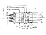
제1도, 제2(a)도 및 제2(b)도에 있어서 전자총 (1)은 후술하는 여러개의 전극과, 이들을 지지하는 여러개의 절연지지체(2)를 갖는다.In FIGS. 1, 2 (a) and 2 (b), the electron gun 1 has several electrodes which will be described later, and several insulating supports 2 supporting them.
상기의 여러개의 전극은 타겟트가 되는 형광면의 적, 녹, 청 각색(各色)의 형광체층(도시하지 않음)을 쏘아부딪히는 세개의 전자비임(3a)(3b)(3c)을 발생하기 위한 세개의 히이타(6a)(6b)(6c)를 내장하는 일렬로 배치된 음극(9a)(9b)(9c)과 이 세개의 음극에 대한 위치에 각각 소정의 전자 비임 통과 구멍 부분이 튀어나오게 설치되어 일체화(一體化) 구조를 가진 제1그리드(11), 제2그리드(12), 제3그리드(13) 제4그리드(14) 수렴전극(15)과 전기의 제3그리드(13)와 제4그리드(14) 사이에 있어서 하나의 커다란 구멍을 가진 보조 전극(16)으로 구성되고 상기의 전열지지체(2)에 심어넣어 고정지지되어 있다.These electrodes are three for generating three electron beams (3a) (3b) (3c) which strike and strike a red, green, and blue phosphor layer (not shown) of the fluorescent surface to be targeted. And arranged in such a manner that the predetermined electron beam through hole portions protrude from the positions of the cathodes 9a, 9b, 9c arranged in a row to house the heaters 6a, 6b, and 6c of the three cathodes. The first grid 11, the
제1그리드(11)와, 제2그리드(12)는 가까이 설치되어 배치된 평판 형상 전극이며, 제3그리드(13)는 제2그리드(12)에 근접 배치되어 접합된 두개의 컵(cup) 형상의 전극(23a)(23b)으로 구성되고 제4그리드(14)는 상기 제3그리드(13)로부터 소정의 거리를 띄워서 배치시켜 접합된 두개의 컵 형상의 전극(24a)(24b)으로 구성되며 수렴전극 (15)은 제4그리드(14)에 용접고정한 한개의 컵형상의 전극(25a)으로 구성된다. 전술한 각 그리드 전극 및 수렴 전극의 각각 컵형상 전극의 바닥 면 및 평판 형상 전극에는 각각 각전자 비임에 정합된 세개의 원형상의 전자비임 통과 구멍 부분이 설치되어 있다.The first grid 11 and the
제1그리드(11) 및 제2그리드(12)의 전자비임 통과 구멍은 비교적 작으며, 제3그리드(13)의 제2그리드(12)에 면한쪽의 전자 비임통과 구멍(33a)(33b)(33c)은 그 보다 크며, 제3그리드(13)의 제4그리드(14)에 면한쪽의 전자 비임통과 구멍(43a)(43b)(43c) 및 제4그리드(14)의 전자비임 통과구멍(34a)(34b)(34c), (44a)(44b)(44c)은 같은 지름으로 비교적 큰 지름이고, 수렴전극 (15)의 전자비임 통과구멍(35a)(35b)(35c)은 그 보다 작다.The electron beam passing holes of the first grid 11 and the
전술한 보조전극(16)은 두개의 컵형상의 전극(26a)(26b)으로 구성되며, 그 바닥 면에는 한개의 큰 트랙피일드(track field) 형상의 구멍(36), (46)이 마련되어 있다.The above-described
보조전극 (16)의 컵형상 전극의 하나를 제6(a)도에 제3그리드 (13)의 컵형상 전극(23b)을 제6(b)도에 나타낸다.One cup-shaped electrode of the
제6도에 나타낸것과 같이 보조전극의 X방향 지름 DX, Y방향 지름 DY는 각각 제3그리드의 세개의 비임 통과 구멍을 포함한 X방향 지름 dx, Y방향지름 dy보다 크게 설정되어 있다.As shown in Fig. 6, the diameters of the X-direction DX and the Y-direction DY of the auxiliary electrode are set to be larger than the diameter of the X-direction dx and the Y-direction diameter dy including the three beam passing holes of the third grid, respectively.
즉, DX>dx, DY>dx이다.That is, DX> dx and DY> dx.
전술한 수렴전극(15)에는 도시하지 않은 양극 단자에 인가되는 약 25Kv의 고전압을 가하는 발브스페이서(bulb spacer)(17)가 부착되어 잇다.The above-mentioned
이와 같은 전자총은 가느다란 유리원통의 넥크(neck)(18)내에 봉입되어져 있고 넥크 하부에는 스텝 핀(stem pin)(19)이 배치되어 있다.Such an electron gun is enclosed in a
이 스템핀(19)은 전자총(1)을 지지고정하는 동시에, 수렴전극(15), 제4그리드 (14) 이외의 각 그리드 전위를 스텝핀(19)를 통하여 외부로부터 공급할 수 있도록 되어 있다.The
이상의 전극구성에 있어서 각 전극전위는 예를들면 다음과 같이 된다.In the above electrode configuration, each electrode potential is as follows, for example.
음극(9)는 약150V의 차단전압으로 유지되고, 이것에 각각 변조신호가 가해진다.The cathode 9 is maintained at a cutoff voltage of about 150 V, to which a modulated signal is applied.
제1그리드 (11)는 접지 전위가, 제2그리드(12)는 약 700V가 인가되며, 제3그리드(13)에는 약 6.5Kv가, 제4그리드(14)에는 약 25Kv의 양극고전압이 인가되며, 보조전극(16)에는 제3그리드(13) 전위와 제4그리드(14) 전위의 대략 중간 전위인 약 16Kv가 인가된다.The first grid 11 has a ground potential, and the
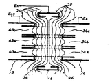
주렌즈 부분에 있어서 이와같은 전극구조를 가진 전자렌즈에서는 그것들의 전위분포가 제3(a)도, 제3(b)도에 나타낸 것과 같이 된다.In the electron lens having such an electrode structure in the main lens portion, their potential distributions are as shown in Figs. 3 (a) and 3 (b).
제3(a)도는 제2(a)도에, 제3(b)도는 제2(b)도에 각각 대응하는 도면이며 등전위선(20)을 나타내고 있으며, 각각 이 전자총의 주렌즈 부분을 설명하기 위하여 간략화한 전극 구조로 나타내고 있다.FIG. 3 (a) is a diagram corresponding to FIG. 2 (a) and FIG. 3 (b) is a diagram corresponding to FIG. 2 (b), respectively, and shows an
제3(a)도, 제3(b)도에서 알 수 있는 바와같이 전자 렌즈의 지름을 결정하는 제3그리드 (13) 제4그리드 (14)의 구멍 부분과 대략같은 부분(도면에서의 점선 내부)에서는 전위 분포는 거의 흩어지지 않고, 제14도에 나타낸 바와같이 두개의 원통 전극의 전극간 거리를 단순히 멀게 했을 때의 주변 전계의 영향을 받지 않는 상태와 동등하게 된다. 따라서 축상 전위분포(軸上電位分布)는 제5도에 나타낸 바와같이 상당히 원만한 것으로 되고, 이 전자 렌즈에 의한 전자 광학적 배율을 감소하며, 또한 구면수차계수(球面收差係數)도 감소하므로 렌즈의 성능은 현저하게 향상된다.As shown in FIG. 3 (a) and FIG. 3 (b), the portion of the
제4도에 나타낸 바와같이 단순히 두개의 전극의 전극간 거리를 멀게하는 것은 실제로는 전술한 거와 같이 넥크내의 다른 전계의 영향을 받아 전위분포가 흐트러지므로 실용화될 수는 없지만, 본 발명과 같이 전자렌즈 구경보다 상딩히 큰 지름을 가진 적어도 한개의 보조 전극을 두개의 전극 사이에 배치시켜, 이 보조전극에 두개의 전극전위의 대략 중간의 전위를 인가하므로서, 넥크내의 다른 불필요한 전계를 차폐시키고 또한 필요한 전자렌즈 부분의 전계를 흐트러지지 않게 할 수 있다.As shown in FIG. 4, simply increasing the distance between electrodes of two electrodes is not practical because the potential distribution is disturbed under the influence of another electric field in the neck as described above. At least one auxiliary electrode with a diameter significantly larger than the lens aperture is disposed between the two electrodes, applying an electric potential approximately midway between the two electrode potentials to the auxiliary electrode, thereby shielding other unnecessary electric fields in the neck and The electric field of the electron lens portion can be prevented from being disturbed.
따라서, 제4도에 나타낸 거와 같이 단순히 두개의 전극간 거리를 멀게 했을 때와 동등한 고성능의 전자렌즈를 형성시킬 수 있다. 이때 보조전극의 구멍은 하나의 큰 구멍으로 하면 좋으며, 다른 전극과 같이 세개의 전자비임 통과 구멍은 필요없으므로 세개의 구멍 부분을 중심 간 거리는 바꾸지 않고 각각 크게 할 수는 없어도 전극간 거리를 크게 하므로서 매위 쉽게 전자렌즈의 성능을 향상시킬 수 있다.Therefore, as shown in FIG. 4, it is possible to form a high-performance electron lens equivalent to a case where the distance between two electrodes is simply increased. At this time, the hole of the auxiliary electrode should be one large hole, and like the other electrode, since three electron beam through holes are not necessary, the three hole parts can be enlarged by increasing the distance between the electrodes without changing the distance between the centers. It can easily improve the performance of the electron lens.
상기 실시예에서는 보조 전극전위의 영향을 완전히 제거하기 위해서는 제3그리드와 제4그리드의 전극 간격을 크게 해가면 갈수록 보조전극의 구멍지름을 제3그리드, 제4그리드의 구멍지름보다 크게 해가지 않으면 안된다. 보조전극의 구멍지름이 충분하지 않는 경우에는 제3그리드, 제4그리드 사이에 형성되는 전자렌즈의 전계가 흐트러져 타겟트위의 비임 스포트는 찌글어지게 된다.In the above embodiment, in order to completely remove the influence of the auxiliary electrode potential, as the electrode gap between the third grid and the fourth grid increases, the hole diameter of the auxiliary electrode does not become larger than that of the third grid and the fourth grid. Can not be done. If the hole diameter of the auxiliary electrode is not sufficient, the electric field of the electron lens formed between the third grid and the fourth grid is disturbed, and the beam spot on the target is crushed.
이 비임 스포트의 찌글어짐을 보조전극의 전위나 구멍형상, 보조 전극의 위치로서 보정할 수 있다.Distortion of this beam spot can be corrected as the potential of the auxiliary electrode, the hole shape, and the position of the auxiliary electrode.
가령 보조전극의 구멍지름이 트랙피일드 형상에서 충분히 크지 않을 경우에는 원형상의 구멍을 가진 제3그리드와 트랙피일드 형상의 보조전극과의 사이 및 마찬가지로 제4그리드와 보조전극사이에 일종의 4극자(極子) 렌즈가 형성되며, 이 두개의 4극자 렌즈의 렌즈 작용 방향이 반대이므로 보조전극의 전위에 따라서 비임 스포트가 찌글어지는 방향이 변화한다.For example, if the hole diameter of the auxiliary electrode is not large enough in the track feed shape, a kind of quadrupole (between the third grid having a circular hole and the track feed shape auxiliary electrode and similarly between the fourth grid and the auxiliary electrode) A lens is formed, and since the direction of lens action of the two quadrupole lenses is opposite, the direction in which the beam spot is crushed according to the potential of the auxiliary electrode changes.
즉, 보조전극전위가 낮은 경우에는 가로길이 비임 스포트가 되고, 높은 경우에는 세로길이 비임스포트가 되므로, 적당한 전위일때 비임 스포트는 원형이 된다.In other words, when the auxiliary electrode potential is low, the beam length becomes a horizontal beam spot, and when the auxiliary electrode potential is high, the beam length becomes a vertical beam spot.
이 적당한 전위라함은 제3그리드 전위와 제4그리드 전위의 중간의 전위보다 근소하게 낮은 전위가 된다.This suitable potential is a potential that is slightly lower than the potential between the third and fourth grid potentials.
이것은 전술한 두개의 4극자 렌즈가 반대 방향의 렌즈 작용을 갖고 있어도, 렌즈 속에서의 비임 속도 및 비임 지름이 다르므로 비임에 작용하는 렌즈력(力)이 달라지기 때문이다.This is because even though the two quadrupole lenses described above have the lens action in the opposite direction, the lens force acting on the beam is different because the beam speed and the beam diameter in the lens are different.
또한 보조전극 전위를 조정하는 방법과 동일한 효과는 보조전극의 제3그리드쪽의 구멍 형상과 제4그리드쪽의 구멍형상을 바꾸는 것으로도 가능하며, 또는 보조전극의 위치 즉, 제3그리드와 보조전극의 간격과 제4그리드와 보조전극의 간격을 조정하는 것으로서도 가능하다.In addition, the same effect as the method of adjusting the auxiliary electrode potential may be achieved by changing the hole shape on the third grid side and the hole shape on the fourth grid side of the auxiliary electrode, or the position of the auxiliary electrode, that is, the third grid and the auxiliary electrode. It is also possible to adjust the spacing between the fourth grid and the auxiliary electrode.
물론 보조전극 이외의 전자렌즈 부분에서 비임의 찌그러짐을 보정해도 좋다는 것은 당연하다.Of course, distortion of the beam may be corrected in the electron lens portions other than the auxiliary electrode.
가령, 전자 비임 형성부에 있어서 사전에 비점수차(非點收差)(astigmatism)를 가지게 해놓고 보조전극에서 이 비점수차를 소거하도록 해도 좋다.For example, the electron beam forming unit may have astigmatism beforehand and the auxiliaries may be canceled out.
전기실시예의 칼라 수상관용 전자총에서는 새도우마스크(shadow mask) 또는 스크린(타겟트)위의 한점에 있어서 세개의 전자 비임을 수렴시키지 않으면 안되지만 이렇게 하기 위해서는 몇개의 방법이 알려져있다.In the color water tube electron gun of the above embodiment, three electron beams must be converged at one point on a shadow mask or a screen (target), but several methods are known to do this.
즉, 양쪽의 전자총 자체를 기울여서 배치시키는 방법이나, 양쪽의 주 렌즈 또는 다른 전자렌즈를 기울여 형성시키는 방법이나, 비대칭 렌즈를 형성시키는 방법등이 있다.That is, a method of tilting and placing both electron guns themselves, a method of tilting both main lenses or other electron lenses, a method of forming an asymmetric lens, and the like.
본 발명에 있어서도 이와같은 것들의 종래의 방법은 그대로 사용할 수 있지만, 본 발명에서는 보조전극의 구조에 의해서도 전술한 수렴을 달성할 수 있다.Also in the present invention, the conventional method of such things can be used as it is, but in the present invention, the above-described convergence can also be achieved by the structure of the auxiliary electrode.
즉 제7(a)도, 제7(b)도에 나타낸 것과 같이, 보조전극의 제4그리드쪽의 X방향 지름 DX4를 제3그리드 쪽의 X방향지름 DX3보다 작게 하므로서 양쪽의 전자 비임을 각각 중앙의 전자 비임쪽으로 근소하게 편향(偏向)시켜서 수렴을 달성하는 것이다.That is, as shown in Fig. 7 (a) and Fig. 7 (b), the electron beams on both sides are made smaller by making the diameter of the X direction DX4 on the fourth grid side of the auxiliary electrode smaller than the diameter of the DX direction on the third grid DX3. Convergence is achieved by slightly deflecting toward the center electron beam.
이것은 X-Z축 단면에 있어서 제4그리드쪽의 보조전극의 전위가 제3그리드쪽의 보조전극의 전위로부터 전자렌즈 부분으로 크게 침입해가서, 이 전위가 그 위치에서의 평균적 전위보다 낮으므로 양쪽의 전자 비임(3a)(3c)은 내부쪽으로 힘을 받기때문이다.This is because the potential of the auxiliary electrode on the fourth grid side invades the electron lens portion largely from the potential of the auxiliary electrode on the third grid side in the XZ axis cross section, so that the potential is lower than the average potential at that position. The
또는 제8(a)도 제8(b)도에 나타내 바와같이 두개의 보조전극(16-1), (16-2)을 사용하여 이들 보조전극에는 제3그리드(13)전위와 제4그리드(14)전위의 대략 중간전위를 인가하는 것이지만, 제4그리드(14)쪽의 보조전극(16-2)의 전위를 제3그리드쪽의 보조전극(16-1)의 전위보다 근소하게 낮게 하는 것으로서도 같은 이유로 전술한 수렴은 달성할 수 있다.Alternatively, as shown in FIG. 8 (a) and FIG. 8 (b), two auxiliary electrodes 16-1 and 16-2 are used to form the
이때 두개의 보조전극의 전극길이도 적당히 가변시켜서 조정해도 좋다.At this time, the lengths of the electrodes of the two auxiliary electrodes may be adjusted as appropriate.
또한 제7(a)도 및 제8(a)도는 제2도와 같이 Y-Z축 단면을, 제7(b)도 및 제8(b)도는 X-Z축 단면을 각각 나타낸다.7 (a) and 8 (a) show the Y-Z axis cross section as shown in FIG. 2, and FIGS. 7 (b) and 8 (b) show the X-Z axis cross section, respectively.
전술한 실시예에서는 보조전극의 전위를 스템핀을 통해서 외부로부터 공급하고 있지만, 본 발명은 이것에 한정되지 않고 저항분할에 의해서 공급해도 좋다.In the above embodiment, the potential of the auxiliary electrode is supplied from the outside through the stem pin, but the present invention is not limited to this, and may be supplied by resistance division.
가령 제9도에 나타낸 바와같이 얇은판 현상의 세라믹 기판(50)에 저항재(51) 및 접속부(52)를 배치한 유리(53)로 코팅(coating)한 저항체(54)를 제10도와 같이 전자총(1)의 각 전극을 지지하는 절연지지체(2)의 배후에 설치하고 저항체의 한쪽을 수렴 전극(15) 또는 제4그리드(14)에 접속하여 양극 고전압(Eb)을 인가하고, 한쪽을 스템핀(19)에 접속하여 외부에서 접지전압(55) 또는 저전압원(56) 또는 저항체(57)에 접속하고 적당한 위치를 보조전극에 접속한다.For example, as shown in FIG. 9, a
이와같은 구성으로 하면 전기적으로는 제1도에 나타낸 바와같이 되고 보조전극에는 양극 고전압(Eb)의 저항체에 의한 분할전압이 공급된다.In such a configuration, as shown in FIG. 1, the divided voltage is supplied to the auxiliary electrode by the resistor of the positive electrode high voltage Eb.
이와같은 저항체(54)로서는 팔라듐, 루테늄계의 산화물 등을 주체로한 것이 적합하고, 특히 산화루테늄과 유리의 혼합물이 적합하다.Such a
제10도에 나타낸 실시예에서는 저항체를 하나의 판 형상으로 하여 절연 지지체(2)의 배후에 설치하고 있지만, 본 발명은 이것에 한정되지 않고 저항체를 보조전극 부분에서 2분할한것, 여러개 이용한것, 절연지지체의 배후에 직접 저항제를 도포한것, 또는 절연지지체 자체를 저항체로서 사용한 것도 본 발명의 범위에 속한다는 것은 말할 나위도 없다.In the embodiment shown in FIG. 10, the resistor is formed in the shape of one plate and is provided behind the insulating
또 제10도에 나타낸 실시예에서는 저항체의 한쪽을 스템핀에 접속하고 있지만, 본 발명은 이것에 한정되지 않고 제3그리드 등 다른 그리드에 접속해도 좋고, 제12도와 같이 제3그리드 전위도 저항 분할에 의하여 공급하도록 해도 좋은 것은 말할 나위도 없다.In the embodiment shown in FIG. 10, one of the resistors is connected to the stem pin. However, the present invention is not limited to this, and may be connected to another grid such as a third grid. Needless to say, it may be supplied.
이상과 같이 보조 전극전위를 저항 분할에 의하여 공급하도록 하면 스템부분에 있어서 중고압의 보조 전극 전위를 공급할 필요가 없고 스템부분 주변에서의 내압(耐壓) 신뢰성이 향상되어 실용성이 풍부한 음극선관을 제공할 수 있다.As described above, by supplying the auxiliary electrode potential by resistance division, there is no need to supply the auxiliary electrode potential of the medium pressure in the stem portion, and the breakdown voltage reliability around the stem portion is improved, thereby providing a practical cathode ray tube. can do.
또한 제3그리드 전위까지도 저항 분할에 의하여 공급하도록 하면 스템부분 주변에서의 내압신뢰성은 더욱 향상되며, 제3그리드 전위를 스템핀을 통해서 저 전위를 제어할 수 있으므로 동적(動的)으로 전자 렌즈의 집속상태를 조정하는 것이 용이하다.In addition, supplying even the third grid potential by resistance division further improves the breakdown voltage reliability around the stem portion, and can control the low potential through the stem pin to dynamically control the electronic lens. It is easy to adjust the focusing state.
또한, 양극 고전압을 고저항체를 통하여 대략 접지전압으로 떨어뜨리는 것은 수상관내에서 발생하는 불필요한 스파크 전류를 대폭 경감할 수 있고, 수상관 동작회로에의 영향을 현저히 작게할 수가 있으므로 수상관 동작회로용 트랜지스터, IC등을 수상관내의 스파크 전류로부터 보호할 수 있다는 큰 잇점도 있다.In addition, dropping the anode high voltage to approximately ground voltage through the high resistor can greatly reduce unnecessary spark currents generated in the water pipe, and can significantly reduce the influence on the water pipe operation circuit. In addition, the IC can protect the IC from spark current in the water pipe.
상기 실시예의 전자총 구조는 상기 미국특허제 3,932,786호 명세서에 나타나있는 구조와는 전혀 다르다.The electron gun structure of this embodiment is completely different from the structure shown in the US Patent No. 3,932,786.
즉, 저항체는 상당히 크게할 수 있으며, 전극에로의 부착도 쉽게 할 수가 있고 제작은 매우 용이하다는 것과, 또 전극간이 넓기 때문에 전극간의 누설 전류도 흐르기 어렵고, 또한 수렴이나 비임의 세로방향과 가로방향의 집속력 조정 및 비임 형상 찌글어짐의 조정이 보조전극의 구조에 따라 용이하게 행할 수 있다.In other words, the resistor can be made quite large, it is easy to attach to the electrode, it is very easy to manufacture, and because the electrode is wide, the leakage current between the electrodes is difficult to flow, and also the longitudinal and transverse directions of convergence and beam The focusing force adjustment and the beam shape distortion can be easily performed according to the structure of the auxiliary electrode.
또한 미국특허제3,932,786호 명세서아 나타낸 전자총과 같이 여러판의 전극 및 그것에 공급하여야 할 여러개의 전위는 필요하지 않고 미국특허 제4,124,810호 명세서의 전자총과 같이 한개의 전극 및 전위로서 미국특허제 3,932,786호 명세서에 나타낸 전자총과 동등한 렌즈성능을 얻을 수가 있다. 그렇기 때문에 반드시 저항 분할 전압은 필요하지는 않으며 스템핀을 통해서도 한개의 중고전압을 얻을 수 있다는 것등 많은 잇점을 가지고 있으므로, 본 발명의 전자총은 고성능 전자렌즈를 가진 전자총으로서 매우 실용성이 높다.Also, it is not necessary to have multiple electrodes and multiple potentials to be supplied thereto, such as the electron gun shown in US Pat. No. 3,932,786, and US Patent No. 3,932,786 as one electrode and potential as in the electron gun of US Pat. Lens performance equivalent to that of the electron gun shown in Fig. 2 can be obtained. Therefore, the resistance splitting voltage is not necessarily required, and since it has many advantages such as being able to obtain a single used voltage through the stem pin, the electron gun of the present invention is very practical as an electron gun having a high performance electron lens.
또한 상기 실시예에서는 보조전극은 제3그리드와 제4그리드 사이에 각각 소정의 간격을 유지하며 배치되어 있었으나 본 발명은 이것에 한정되지 않고 제13도에 나타낸 바와같이 보조전극이 제3그리드, 제4그리드의 한쪽 또는 양쪽에 덮혀 있어도 본 발명의 효과가 변하는 것은 아니다.In addition, in the above embodiment, the auxiliary electrode is disposed while maintaining a predetermined interval between the third grid and the fourth grid, but the present invention is not limited thereto, and as shown in FIG. The effect of the present invention does not change even if it is covered on one or both sides of the four grids.
제13도에 나타낸 바와같이 보조전극이 양쪽의 전극을 덮었을 경우에는 넥크 내벽의 불필요한 전계의 영향을 완전히 차폐할 수가 있으므로 종리의 칼라 수상관에 있어서 문제로 되는 수렴의 넥크 내벽의 전하(電荷)에 의하여 경시변화(經時變化)들을 완전하게 방지할 수 있는 성능이 우수한 칼라 수상관을 제공할 수 있다.As shown in FIG. 13, when the auxiliary electrode covers both electrodes, it is possible to completely shield the influence of the unnecessary electric field of the inner wall of the neck. By means of this, it is possible to provide a color receiving tube having excellent performance to completely prevent changes over time.
또한 전술한 실시예의 주 렌즈 부분에서는 제3그리드와 제4그리드 두 개의 전극으로된 바이포텐샬(bipotential)형 렌즈를 기본으로 하고 그 전극사이에 큰 구멍을 가진 보조전극을 배치한 구성으로 되어 있지만 본 발명은 이것에 한정되지 않으며, 제14(a)도에 나타낸 바와같이 유니포텐샬(unipotential)형 렌즈를 기본으로 해도좋고, 제14(b)도에 나타낸 바와같이 콰드라포텐샬(quadru potential)형 렌즈를 기본으로 해도 좋고, 제14(c)도에 나타낸 바와같이 페리오딕포텐샬(periodic potential)형 렌즈를 기본으로 해도 좋으며 기타 트라이포텐샬(tripotential)형 렌즈를 기본으로 해도 본 발명의 본질이 변하는 것은 아니다.In addition, in the main lens part of the above-described embodiment, a bipotential lens composed of two electrodes of the third and fourth grids is used, and an auxiliary electrode having a large hole is disposed between the electrodes. The invention is not limited to this, and may be based on a unipotential lens as shown in Fig. 14 (a), and a quadra potential lens as shown in Fig. 14 (b). May be used as the basis, or may be based on a periodic potential lens as shown in FIG. 14 (c), and the nature of the present invention does not change even when the other tripotential lens is used as a basis. .
또한 제14(a)도 내지 제14(c)도는 주 렌즈 부분의 대체적인 구성도를 나타낸 것으로, 각각 전자렌즈를 형성시키는 부분에 전부 보조전극을 배치하여 본 발명을 적용하고 있지만, 주요한 전자렌즈 부분에만 본 발명을 적용해도 좋은 것은 말할 나위도 없다.14 (a) to 14 (c) show an alternative configuration of the main lens portion, and the present invention is applied to all the auxiliary electrodes at the portions forming the electron lens, but the main electron lens is applied. It goes without saying that the present invention may be applied only to a part.
특히 제14(b)도, 제14(c)도에 나타낸 렌즈계에서는 제3그리드(G3)의 전압을 약 8-9Kv로 설정할 수 있으므로, 물점형성부(物點形成剖)로 부터의 전자 비임의 질을 가장 좋은 상태로 사용할 수 있고, 종합적인 전자총의 성능은 더욱 좋아진다.In particular, in the lens system shown in Fig. 14 (b) and Fig. 14 (c), the voltage of the third grid G3 can be set to about 8-9 Kv, so the electron beam from the water spot forming portion is formed. Quality can be used in the best condition, and the performance of the gun is even better.
또한 전술한 실시예에서는 세개의 전자총을 가로 방향으로 일렬로 일체화시킨 구조로 되어있지만, 본 발명은 이것에 한정되지 않고, 정삼각형상으로 세개의 전자총을 배치한 구조로 된것이나, 기타 여러개의 전자총을 배치한 구조로 된것이나, 또는 하나의 전자총 구조로된 것이라도 본 발명을 적용시킬 수 있다는 것은 말할 나위도 없다.In the above embodiment, the three electron guns are integrated in a row in the horizontal direction. However, the present invention is not limited thereto, but the three electron guns are arranged in an equilateral triangle. Needless to say, the present invention can be applied to the structure of the arrangement or to the structure of one electron gun.
이상과 같이 본 발명에 따르면, 주 렌즈 부분이 각각 전자 비임 통과구멍을 가진 적어도 두개의 전극과 적어도 일부분이 이것들의 전극 사이에 위치하며, 이것들의 전극이 가진 전자 비임 통과구멍 보다 큰 구멍을 가진 적어도 한개의 보조전극을 구비하고, 전술한 대향하는 두개의 전극에는 상대적으로 저위(低位)와 상대적으로 고위(高位)의 전위가 인가되어 전술한 보조전극에는 상대적으로 중위의 전위가 인가된 구조로 하므로서 실질적으로 전극간 거리가 긴 장촛점렌즈를 실용상 문제없이 형성시킬 수 있다.According to the present invention as described above, at least two electrodes each having an electron beam through hole and at least a portion thereof are located between these electrodes, and at least those having a hole larger than the electron beam through hole of these electrodes. It is provided with one auxiliary electrode, and the lower and relatively high potentials are applied to the two opposing electrodes described above, so that the above-mentioned auxiliary electrode has a relatively middle potential applied thereto. Substantially long long focal length lenses can be formed without problems in practical use.
본 발명의 전자총은 구조가 간단하여 제조하기 쉬우며, 실용성이 풍부한 고성능의 음극선관용 전자총을 제공할 수가 있는 것이다.The electron gun of the present invention is simple in structure and easy to manufacture, and can provide a high-performance cathode ray gun for practical use.
또한 본 발명의 전자총에서는 여러개의 전자 비임의 간격, 즉 전자 비임 통과구멍간의 거리를 크게할 필요가 없이 고성능의 전자총을 얻을 수 있으므로 칼라 수상관에 있어서는 평향 전력이 적으며 또한 수렴 품위가 양호한 고성능 전자총으로서 사용할 수 있는 것이다.In addition, in the electron gun of the present invention, a high-performance electron gun can be obtained without increasing the distance between the multiple electron beams, that is, the distance between the electron beam through-holes. It can be used as.
Claims (5)
Applications Claiming Priority (3)
| Application Number | Priority Date | Filing Date | Title |
|---|---|---|---|
| JP28612 | 1984-02-20 | ||
| JP59028612A JPS60175343A (en) | 1984-02-20 | 1984-02-20 | Electron gun for cathode-ray tube |
| JP59-28612 | 1984-02-20 |
Publications (2)
| Publication Number | Publication Date |
|---|---|
| KR850006246A KR850006246A (en) | 1985-10-02 |
| KR890002362B1 true KR890002362B1 (en) | 1989-07-01 |
Family
ID=12253387
Family Applications (1)
| Application Number | Title | Priority Date | Filing Date |
|---|---|---|---|
| KR1019840008580A KR890002362B1 (en) | 1984-02-20 | 1984-12-31 | Electron gun |
Country Status (2)
| Country | Link |
|---|---|
| JP (1) | JPS60175343A (en) |
| KR (1) | KR890002362B1 (en) |
Families Citing this family (1)
| Publication number | Priority date | Publication date | Assignee | Title |
|---|---|---|---|---|
| JP2002075240A (en) * | 2000-08-24 | 2002-03-15 | Toshiba Corp | Cathode-ray tube device |
-
1984
- 1984-02-20 JP JP59028612A patent/JPS60175343A/en active Granted
- 1984-12-31 KR KR1019840008580A patent/KR890002362B1/en not_active IP Right Cessation
Also Published As
| Publication number | Publication date |
|---|---|
| KR850006246A (en) | 1985-10-02 |
| JPH0552020B2 (en) | 1993-08-04 |
| JPS60175343A (en) | 1985-09-09 |
Similar Documents
| Publication | Publication Date | Title |
|---|---|---|
| US4124810A (en) | Electron gun having a distributed electrostatic lens | |
| US5162695A (en) | Electron gun assembly for a color cathode ray tube | |
| US4168452A (en) | Tetrode section for a unitized, three-beam electron gun having an extended field main focus lens | |
| KR890002362B1 (en) | Electron gun | |
| KR890002361B1 (en) | Electron gun | |
| CA2039501C (en) | Color picture tube having inline electron gun with focus adjustement means | |
| KR900002078B1 (en) | Color crt | |
| CA1174263A (en) | Electron gun with improved beam forming region | |
| KR900003905B1 (en) | Electron gun structure | |
| EP0810625B1 (en) | Electron gun assembly for cathode ray tube | |
| KR100221926B1 (en) | Color cathode ray tube having improved resolution | |
| US6456018B1 (en) | Electron gun for color cathode ray tube | |
| US5633567A (en) | Display device and cathode ray tube | |
| KR100768173B1 (en) | Cathode ray tube including an electron gun in a coated tube neck | |
| KR100213786B1 (en) | An electron gun for color crt | |
| KR100581849B1 (en) | Electron gun for cathode ray tube | |
| JP2692837B2 (en) | Color picture tube equipment | |
| KR100439263B1 (en) | A Electron Gun Of The Color Cathode Ray Tube | |
| KR100189612B1 (en) | Electron gun of electrode structure for cathode ray tube | |
| CA1058683A (en) | Tetrode section for a unitized three-beam electron gun having an extended field main focus lens | |
| KR920007951B1 (en) | Color picture tube having in line-type electron gun | |
| KR100313897B1 (en) | electron gun for color cathode ray tube | |
| JPH0552019B2 (en) | ||
| JPH0564410B2 (en) | ||
| KR20020072866A (en) | Electron gun for color cathode ray tube |
Legal Events
| Date | Code | Title | Description |
|---|---|---|---|
| A201 | Request for examination | ||
| G160 | Decision to publish patent application | ||
| E701 | Decision to grant or registration of patent right | ||
| GRNT | Written decision to grant | ||
| FPAY | Annual fee payment |
Payment date: 20040630 Year of fee payment: 16 |
|
| EXPY | Expiration of term |