KR890001905B1 - Control unit inclunding a circuit for controlling and setting control data for a digital processing circuit - Google Patents
Control unit inclunding a circuit for controlling and setting control data for a digital processing circuit Download PDFInfo
- Publication number
- KR890001905B1 KR890001905B1 KR1019840004835A KR840004835A KR890001905B1 KR 890001905 B1 KR890001905 B1 KR 890001905B1 KR 1019840004835 A KR1019840004835 A KR 1019840004835A KR 840004835 A KR840004835 A KR 840004835A KR 890001905 B1 KR890001905 B1 KR 890001905B1
- Authority
- KR
- South Korea
- Prior art keywords
- circuit
- processing circuit
- remote control
- control
- signal
- Prior art date
Links
Images


Classifications
-
- H—ELECTRICITY
- H03—ELECTRONIC CIRCUITRY
- H03J—TUNING RESONANT CIRCUITS; SELECTING RESONANT CIRCUITS
- H03J1/00—Details of adjusting, driving, indicating, or mechanical control arrangements for resonant circuits in general
- H03J1/0008—Details of adjusting, driving, indicating, or mechanical control arrangements for resonant circuits in general using a central processing unit, e.g. a microprocessor
-
- H—ELECTRICITY
- H04—ELECTRIC COMMUNICATION TECHNIQUE
- H04N—PICTORIAL COMMUNICATION, e.g. TELEVISION
- H04N5/00—Details of television systems
- H04N5/44—Receiver circuitry for the reception of television signals according to analogue transmission standards
Landscapes
- Engineering & Computer Science (AREA)
- Multimedia (AREA)
- Signal Processing (AREA)
- Computer Hardware Design (AREA)
- Microelectronics & Electronic Packaging (AREA)
- Selective Calling Equipment (AREA)
- Details Of Television Systems (AREA)
Abstract
Description
제1도는 디지틀신호 처리회로를 가진 텔레비전수상기의 기본적인 구성을 표시하는 블록도.1 is a block diagram showing the basic configuration of a television receiver having a digital signal processing circuit.
제2도는 디지틀신호 처리회로 조정장치의 종래예를 표시한 요부의 블록도.2 is a block diagram of a main portion showing a conventional example of a digital signal processing circuit adjusting apparatus.
제3도는 본 발명의 한 실시예에 있어서의 제어장치의 구성을 표시한 블록도.3 is a block diagram showing the configuration of a control device according to an embodiment of the present invention.
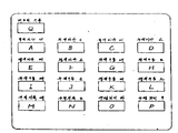
제4도는 본 발명에 있어서 통상상태에 있어서의 원격제어신호 송신기의 조작부의 일례를 표시한 정면도.4 is a front view showing an example of an operation unit of a remote control signal transmitter in a normal state in the present invention.
제5도는 본 발명의 한 실시예에 있어서의 제어장치의 구체적 예를 기능적으로 나타낸 블록도.5 is a block diagram functionally showing a specific example of the control apparatus in one embodiment of the present invention.
제6도는 본 발명에 있어서 조정상태에 있어서의 원격제어신호 송신기 조작부의 일례를 표시한 정면도.6 is a front view showing an example of the remote control signal transmitter operation unit in the adjusted state in the present invention.
제7도는 본 발명의 다른 실시예에 있어서의 제어장치의 구성을 표시한 블록도.Fig. 7 is a block diagram showing the configuration of a control device in another embodiment of the present invention.
* 도면의 주요 부분에 대한 부호의 설명* Explanation of symbols for the main parts of the drawings
1 : 제어용 마이크로컴퓨터 2 : 조작키이1: control microcomputer 2: operation key
3 : 원격조정송신기 4 : 원격조정신호수신회로3: remote control transmitter 4: remote control signal receiving circuit
5 : 기억소자 6 : 선국회로5
9 : 디지틀신호처리회로 10 : 색신호출력회로9: digital signal processing circuit 10: color signal output circuit
22 : 절환회로 23 : 원격조정신호판별회로22: switching circuit 23: remote control signal discrimination circuit
24 : 선국데이터제어회로 25 : 음성데이터제어회로24: Tuning data control circuit 25: Voice data control circuit
26 : 색상데이터제어회로 27 : 전원제어회로26: color data control circuit 27: power supply control circuit
28 : 메모리기록제어회로 29 : 차단제어회로28: memory write control circuit 29: cutoff control circuit
30 : 구동데이터제어회로 31 : 수직진폭제어회로30: drive data control circuit 31: vertical amplitude control circuit
32 : 수평위치제어회로32: horizontal position control circuit
본 발명은, 원격제어신호를 발신 및 수신하는 회로를 구비하고, 상기 원격제어신호에 의해서 신호처리회로, 선국회로의 제어를 할 수 있는 컬러텔레비전 수상기에 이용할 수 있는 제어장치에 관한 것이다.The present invention relates to a control apparatus having a circuit for transmitting and receiving a remote control signal and which can be used for a color television receiver capable of controlling a signal processing circuit and a tuning circuit by the remote control signal.
근년, 컬러텔레비전 수상기에 있어서는 마이크로컴퓨터나 디지틀 신호처리회로등을 채용하여, 디지틀데이터에 의해서 텔레비전 신호를 처리 혹은 제어하는 장치가 개발되어 오고 있다. 이와 같이 신호처리를 디지틀신호의 형태로 행하면, 그 초기 데이터를 기억할 필요가 있다. 이것은, 그 초기 데이터를 기준으로 해서, 통상 동작시의 컬러텔레비전 수상기에서 필요한 신호를 검출하고, 이 신호와 상기 초기 데이터를 제어용마이크로컴퓨터로 비교 연산처리해서, 컬러텔레비전 수상기가 항상 정확히 동작하도록 제어하기 위해서이다. 그 일례로써 자동 화이트 밸런스조정을 들 수 있다. 이 자동 화이트 밸런스 조정수단으로써, 적, 록, 청의 각색에 대해서 저전압전원과 고전압 전원을 구비하고, 화이트 밸런스를 포함하는 모든 조정을 끝낸 컬러텔레비전 수상기의 색신호 출력회로의 입력으로써 상기 저, 고전압원으로부터의 각각의 기준 원색전압을 가하고, 이 때의 각각의 비임전류를 전압으로해서 검출하여, 디지틀신호로 변환해서 초기 기준데이터로 해서 기억소자에 기억시킨다. 이것을 적, 청, 록의 각각에 대해서 행한다. 그리고 컬러텔레비전 수상기의 통상의 동작중에 있어서, 귀선소거 기간에 상기 각 색의 저전압, 고전압을 입력으로 해서 색신호 출력회로에 가하고, 이 때의 어느 1개의 원색의 비임전류를, 상기 초기 기준데이터와 비교연산해서 화이트 밸런스의 벗어짐을 측정 검출하고, 이 벗어짐의 정도에 따라서 다른 원색의 비임전류가 미리 기억된 3원색의 비율에 일치하도록 색신호의 DC레벨 및 이득을 조정하는 방법이 제안되고 있다. 본 발명은 이 때의 상기 기준 데이터를 조정하는 수단에 관한 것이다.In recent years, a color television receiver has been developed that employs a microcomputer, a digital signal processing circuit, or the like to process or control a television signal by digital data. When signal processing is performed in the form of a digital signal in this manner, it is necessary to store the initial data. Based on the initial data, it detects a signal required by a color television receiver in normal operation, compares the signal with the initial data with a control microcomputer, and controls the color television receiver to always operate correctly. For that. One example is automatic white balance adjustment. The automatic white balance adjusting means includes a low voltage power supply and a high voltage power supply for each color of red, green, and blue, and inputs the color signal output circuit of the color television receiver that has completed all adjustments including white balance from the low, high voltage source. Each reference primary voltage is applied, and each beam current at this time is detected as a voltage, converted into a digital signal, and stored in the storage element as initial reference data. This is done for each of red, blue and green. In the normal operation of the color television receiver, the low voltage and the high voltage of the respective colors are input to the color signal output circuit during the blanking period, and the beam current of any one primary color at this time is compared with the initial reference data. The method of calculating and detecting the deviation of the white balance by calculation, and adjusting the DC level and the gain of a color signal so that the beam current of different primary colors correspond to the ratio of three primary colors previously stored according to the degree of this deviation are proposed. The present invention relates to means for adjusting the reference data at this time.
또, 한편 이와 같이 이지틀 신호 처리회로를 사용한 컬러텔레비전 수상기에 있어서는, 완성된 컬러텔레비전 수상기에 어떠한 고장이 발생해서 주변부품의 교환을 행하여 상기 초기 데이터를 변경할 필요가 생긴다. 이에 대해서 종래에는 조정요의 지그를 사용해서 필요한 조정을 행하고 있었다.On the other hand, in the color television receiver using the easy signal processing circuit in this way, a failure occurs in the completed color television receiver, so that it is necessary to replace the peripheral parts to change the initial data. On the other hand, conventionally, necessary adjustment was performed using the jig of adjustment yaw.
여기서, 먼저 일반적인 디지틀화된 컬러텔레비전 수상기의 구성을 제1도를 사용해서 설명한다.First, a configuration of a general digitalized color television receiver is described with reference to FIG.
제1도에 있어서, (1)은 제어용마이크로 컴퓨터, (2)는 전원의 온·오프, 선국, 음량등의 제어를 행하기 위한 복수의 키이로 이루어진 조작키이, (3)은 원격제어송신기, (4)는 원격제어송신기(3)로부터의 원격제어신호를 수신하는 수신회로, (5)는 기억소자, (6)은 선국회로, (7)은 튜우너, (8)은 중간주파증폭회로, (9)는 디지틀신호 처리회로, (10)은 색출력회로, (11)은 구동회로, (12)는 음국선관, (13)은 음성출력회로, (14)는 음성출력장치이다.In Fig. 1,
제1도의 기본동작을 이하에 설명한다. 조작키이(2) 혹은 원격제어송신기(3)로부터의 신호에 의해서 제어용마이크로컴퓨터(1)는 어떤 조작인가를 판별하여, 기억소자(5), 선국회로(6), 디지틀신호 처리회로(9)등을 제어한다. 여기서, 선국데이터나 신호처리의 초기치가 되는 데이터는 기억소자(5)에 기억되어 있으며, 적의 판독되고, 또 기록된다. 이 기억소자(5)로써는 불휘발성의 메모리, 예를들면 M NOS메모리, FA MOS메모리등을 사용할 수 있고, 또 배터리에 의해 전원이 백업된 휘발성 메모리를 사용해도 된다.The basic operation of FIG. 1 will be described below. The
예를 들면, 조작키이(2) 혹은 원격제어송신기(3)에 의해서 선국조작이 행해지면, 제어용마이크로컴퓨터(1)및 선국회로(6)가 동작하고, 기억소자(5)에서 선국데이터를 판독하고, 그 선국데이터에 따른 동조전압을 튜우너(7)에 인가한다. 튜우너(7)에서 선택된 텔레비전 신호는 음성중간주파증폭회로. 검출회로(8)를 지나서 영상, 음성신호가 되어, 디지틀신호 처리회로(9)에 가해진다. 디지틀신호 처리회로(9)는, 중간주파증폭회로·검파회로(8)로부터의 신호를 먼저 애널로그-디지틀변환기(도시하지 않음)에 의해 디지틀신호로 변환하여, 영상·음성의 신호처리를 행하고, 제어용마이크로컴퓨터(1)로부터의 지령에 의해서 각종 제어를 행하며, 그 후 디지틀-애널로그변화기(도시하지 않음)에 의해서 애널로그신호로 변환되어, 색신호는 라인(16)을 통해서 색신호 출력회로(10)에 공급한다. 색신호 출력회로(10)는, 제어용마이크로컴퓨터(1)로부터 라인(15)을 통해서 공급되는 디지틀 데이터에 의해서 색신호의 DC레벨과 이득을 조정할 수 있다. 또한, 도시하지 않았으나 상기 디지틀 데이터는 디지틀-애널로그변환기에 의해서 애널러그 데이터로 변환되어서 색신호 출력회로(10)에 가해진다. 이 색신호 출력회로(10)에서 조정된 색신호는 구동회로(11)에 가해져 수상관(12)을 구동한다. 한편, 음성신호는 라인(17)을 통해서 음성출력회로(13)에 가해지고, 음성출력장치(14)를 구동한다.For example, when the tuning operation is performed by the
이와 같이. 디지틀화된 텔레비전 수상기에서는, 색신호 출력회로(10)의 동작설명에도 있는바와 같이, 각종 조정은 거의 제어용마이크컴퓨터(1)로부터의 디지틀 데이터를 사용해서 행하기 때문에, 종래의 애널로그 방식의 텔레비전 수상기와 같이, 볼륨이나 트리머 콘덴서등, 외부에서 조정할 수 있는 부품은 없어지는 경향에 있다.like this. In the digitalized television receiver, as described in the operation of the color
따라서, 이와 같은 디지틀 텔레비전 수상기의 조정을 행할 경우, 종래에는, 제2도에 표시한 바와 같이, 특별한 조정지그를 사용하고 있었다. 제2도는, 종래의 디지틀 텔레비전 수상기의 조정방법의 일례를 표시한 것이다. 제1도와 같은 번호를 붙인것을 같은 기능의 블록이고, 여기서는 설명에 필요한 부분만을 뽑아내서 도시하고 있다. 제2도에 있어서, (18)은 조정용지그, (19)는 통상동작시와 조정시의 신호절환기이다. 이상과 같이 구성된 조정장치에 대해서 동작을 설명한다.Therefore, when adjusting such a digital television receiver, a special adjustment jig was conventionally used as shown in FIG. 2 shows an example of an adjustment method of a conventional digital television receiver. The same numbers as in FIG. 1 are blocks of the same function, and only the parts necessary for explanation are shown here. In Fig. 2,
통상동작시는, 신호절환기(19)는 단자(X)축에 접속되어 있으며, 기억소자(5)의 제어라인(20)및 디지틀 신호처리회로(9), 색신호출력회로(10)의 제어라인(21)은 제어용마이크로컴퓨터(1)에 접속되어있다. 조정을 행할때는 신호절환기(19)를 단자(Y)축에 접속한다. 이것에 의해서, 기억소자(5)의 제어라인(20)과 디지틀신호처리회로(9), 색신호출력회로(10)의 제어라인(21)은, 함께 조정용지그(18)에 접속된다. 이 조정상태에 있어서, 조정용지그(18)는, 디지틀 신호처리회로(9), 색신호 출력회로(10)에 제어라인(21)을 개재해서 디지틀 데이터를 보내고, 필요한 조정을 행한다. 조정이 완료되면, 조정용지그(18)는 제어라인(20)을 개재해서, 조정된 디지틀 데이터를 기억소자(5)에 기록한다. 이와같이해서 조정이 행해진다.In normal operation, the
상기와 같은 구성에 있어서는, 조정을 할때 특별한 조정지그를 필요로 하고, 시장에서 부품을 교환한 경우의 간단한 재조정등에서도 제어라인을 절환하고 조정지그를 준비하는 등, 일손이 걸린다고 하는 문제점을 가지고 있다.In the above configuration, there is a problem that a special adjustment jig is required at the time of adjustment, and even a simple re-adjustment in the case of replacing parts in the market takes one hand, such as switching the control line and preparing the adjustment jig.
본 발명은, 상기 종래의 문제점을 해소하는 것으로써, 특별한 조정용지그없이 텔레비전 수상기가 구비하고 있는 원격제어신호 송신기의 원격제어신호에 의해서 주요한 조정을 할 수 있는 제어장치를 제공하는 것을 목적으로 한다.An object of the present invention is to provide a control device capable of making major adjustments by remote control signals of a remote control signal transmitter provided in a television receiver without a special adjustment jig. .
본 발명의 제2의 목적은, 조정시에만 기억소자의 내용을 변경할 수 있도록 해서 기억소자의 기억내용의 보호를 도모하는 것이었다.A second object of the present invention is to protect the memory contents of the memory element by changing the contents of the memory element only during adjustment.
본 발명에 의한 제어장치는, 신호처리회로와, 상기 신호처리회로의 제어데이터를 기억할 수 있는 기억소자와, 상기 신호처리회로 및 기억소자를 제어하는 제어회로와, 원격제어신호를 발신 및 수신하는 회로와, 상기 제어회로를 제1의 사용형태와 제2의 사용형태에서는 동일한 상기 원격제어신호에 의해서 상기 신호처리회로의 제어데이터를 조정하고, 조정후의 제어데이터를 상기 기억소자에 기록하도록 한것이며, 상기 원격제어신호를 사용해서 조정이 행하여짐으로서, 새삼스럽게 조정용지그를 사용할 필요가 없고, 용이하게 신호처리회로의 조정이 행하여지는 것이다.The control apparatus according to the present invention includes a signal processing circuit, a storage element capable of storing control data of the signal processing circuit, a control circuit for controlling the signal processing circuit and the memory element, and a remote control signal for transmitting and receiving. In the first and second usage forms of the circuit and the control circuit, the control data of the signal processing circuit is adjusted by the same remote control signal, and the control data after the adjustment is recorded in the storage element. Since the adjustment is performed using the remote control signal, it is not necessary to use the adjustment jig again, and the signal processing circuit can be easily adjusted.
이하 본 발명의 한 실시예에 대해서 도면을 참조하면서 설명한다. 제3도는 본 발명의 일실시예에 있어서의 제어장치를 표시한 것이다. 도면에 있어서, 제어용마이크로컴퓨터(1), 조작키이(2), 원격제어송신기(3), 원격제어신호 수신회로(4), 기억소자(5), 선국회로(6), 튜우너(7), 중간주파증폭·검파회로(8), 디지틀신호처리회로(9), 색신호 출력회로, 구동회로(11), 음극선과(12), 음성출력회로(13), 음성출력장치(14)에 대해서는 제1도와 동일한 기능을 가지고 있는 것이므로, 동일한 번호를 붙이고 있다. 여기서, (22)는, 통상 동작상태와 조정상태를 절환하기 위한 절환회로이다.Hereinafter, an embodiment of the present invention will be described with reference to the drawings. 3 shows a control device in one embodiment of the present invention. In the figure, a
여기서, 통상 동작상태라 함은, 일반적으로 텔레비전 수상기를 시청하는 상태를 말하고, 이 때의 원격제어송신기(3)의 조작면 구성의 일례를 제4도에 표시한다.Here, the normal operation state generally refers to a state of watching a television receiver, and an example of the operation surface configuration of the
제4도의 각 장방형상 틀(키이를 표시)내의 알파벳(A)~(Q)는, 원격제어신호의 부호의 종류를 나타낸것으로써, 설명을 용이하게 하기 위하여 붙였다.Letters (A) to (Q) in each rectangular frame (indicative of a key) in FIG. 4 indicate the type of code of a remote control signal, and are attached for ease of explanation.
원격제어신호의 부호(A)~(Q)기능의 일례로써, 통상동작상태에 있어서, (A)~(L)는 선국키이로써 사용한다. 이들 선국키이 (A)~(L)를 조작하며, 선국회로(6)를 제어해서 희망하는 채널을 수신할 수 있다. 또, (M)(N)은 음량의 대소를 조작하는 키이, (O)(P)는 색의 농도 (짙음,엷음)를 제어하는 키이, (Q)는 전원의 온·오프를 제어하는 키이이다. 이들 (M)~(P)(Q)의 키이를 조작하면 제어용마이크로컴퓨터(1)를 통해서 디지틀신호처리회로(9), 전원회로(40)를 제어하여 상기한 각 처리를 행한다.As an example of the functions (A) to (Q) of the remote control signal, in the normal operation state, (A) to (L) is used as the tuning key. These tuning keys operate (A) to (L), and control the
다음에 제5도를 사용해서 더욱 상세히 통상 동작상태 및 조정상태의 동작에 대해서 설명한다. 제5도는 제3도의 요부구성을 기능적으로 블록화해서 나타낸 도면이다. 제5도에 있어서, 절환회로(22)를 단자(X)측에 접속하면 통상 동작상태이고, 절환회로(22)를 단자(Y)측에 접속하면 조정상태가 된다. 이 조정상태에 있어서, 원격제어송신기(3)로부터의 원격제어신호에 의해서 음극선과(12)의 차단레벨, 색신호의 구동량, 영상의 수직진폭, 수평진폭의 각 조정이 가능하게 된다.Next, the operation of the normal operation state and the adjustment state will be described in more detail with reference to FIG. FIG. 5 is a diagram functionally blocking the main components of FIG. In FIG. 5, when the switching
제5도에 있어서, (23)은 제어용마이크로컴퓨터(1)의 기능의 하나로 원격제어신호를 판별하는 판별수단(24)는 원격제어신호중 선국데이터 (A)~(L)를 받아서 선국회로(6)를 제어하는 수단, (25)는 원격제어신호 (M)(N)를 받아, 음량의 대소의 데이터를 제어하는 수단, (26)은 원격제어신호 (O)(P)를 받아 색상의 농·담 데이터를 제어하는 수단, (27)은 원격제어신호(Q)를 받아, 기억소자(5)로의 데이터기록을 제어하는 수단, (29)는 원격제어신호(A)~(F)를 받아, 색신호 출력회로(10)의 차단데이터를 제어하는 수단, (30)은 원격제어신호(G)~(L)를 받아, 색신호 출력회로(10)의 구동데이터를 제어하는 수단, (31)은 원격제어신호(M)(N)를 받아 수직진폭의 데이터를 제어하는 수단, (32)는 원격제어신호(O)(P)를 받아, 수평위치의 데이터를 제어하는 수단이다.In Fig. 5,
여기서, 알파벳으로 표시되어 있는 원격제어신호(A)~(Q)는, 제4도의 원격제어 송신기의 일례로써 표시한 부호와 대응하고 있다. 또, 음량의 대소, 색상의 농담, 수직진폭, 수평위치등에 제어는, 제어용마이크로컴퓨터(1)로부터 디지틀신호 처리회로(9)에 제어데이터를 보냄으로써 행하여진다.Here, the remote control signals A to Q displayed in alphabetical letters correspond to the codes indicated as an example of the remote control transmitter in FIG. In addition, control of the volume level, color tone, vertical amplitude, horizontal position, and the like is performed by sending control data from the
다음에 제5도에 있어서 동작을 설명한다. 원격제어 송신기(3)로부터 보내지는 조작명형(펄스부호신호)은, 원격제어신호 수신기(4)를 개재해서, 원격제어신호 판별수단(23)에 가해진다. 원격제어신호 판별수단(23)은, 원격제어신호(A)~(Q)가 무엇인가를 판별해서, 각 조작에 대응하는 제어수단에 신호를 보낸다. 이제, 절환회로(22)가 단자(X)축에 접속되어 있을 때는 통상 동작상태이고, 원격제어신호 (A)~(L)는 선국데이터제어수단(24)에 가해져 선국회로(6)를 구동한다. 또, 원격제어신호(M)(N)는 음량대소의 제어수단(25)에 가해져 디지틀신호 처리회로(9)에서 음량의 대소가 제어된다. 원격제어신호(O)(P)는 색상의 농담제어수단(26)에 가해지고, 디지틀신호 처리회로(9)에서 색상의 농담이 제어된다. 원격제어신호(Q)는 전원 개폐 제어수단(27)에 가해져, 전원회로(40)를 개폐 제어한다. 이상은, 통상적인 텔레비전 수상기를 볼 때의 동작이다.Next, the operation in FIG. 5 will be described. The operation name type (pulse code signal) sent from the
다음에, 절환회로(22)가 단자(Y)측에 접속되었을 때는 조정상태이고, 원격제어신호(A)~(Q)는 제어수단(28)(29)(30)(31)(32)에 가해지게 되는 것이다.Next, when the switching
통상 동작상태와 같은 원격제어신호(A)~(Q)에 있어서, 신호(A)~(F)는 차단데이터 제어수단(29)에 가해져서, 색신호출력회로(10)의 차단을 조정한다. 또, 원격제어신호(G)~(L)는 구동데이터제어수단(30)에 가해져, 색신호 출력회로(10)의 구동량(DC레벨과 이득)을 조정한다. 원격제어신호(M)(N)는 수직진폭제어수단(31)에 가해져, 디지틀신호 처리회로(9)에서 수직진폭을 조정한다. 원격제어신호(O)(P)는 수평위치제어수단(32)에 가해져, 디지틀신호 처리회로(9)에서 수평진폭을 조정한다. 원격제어신호(Q)는, 메모리기록 제어수단(28)에 가해져, 상기 원격제어신호(A)~(P)로 조정된 각 데이터를 디지틀신호처리회로(9)의 초기데이터로써 기억소자(5)에 기록한다.In the remote control signals A to Q as in the normal operation state, the signals A to F are applied to the cutoff data control means 29 to adjust the cutoff of the color
상기 조정상태에서의 원격제어신호 송신기(3)의 조작면을 표시하면 제6도와 같이된다. 색신호 출력회로(10)에서는 적색, 녹색, 청색의 3색의 제어가 필요하며, 각각의 색에 대해서 차단데이터의 대·소 조정키이(A)~(F)와 구동데이터의 대·소조정키이(G)~(L)로 조정을 행한다. 또, 수직진폭의 대·소 조정키이(M)(N), 수평위치의 좌·The operation surface of the remote
우조정키이(O)(P)에 의해서 각각의 조정을 행할 수 있다. 도, 기억소자(5)로의 각 데이터의 기록은 키이(Q)에 의해서 행할 수 있다. 또한, 상기한 조정량은 키이를 누르고 있는 시간으로 제어할 수 있다. 이와 같은 제어장치를 사용함으로서, 같은 원격제어신호를 사용해서, 절환회로(22)가 통상 동작상태로 절환되었을 때는, 제4도에 표시한 바와 같이 통상 텔레비전 수상기를 조작하는 것과 마찬가지의 기능을 가지며, 조정상태로 절환되었을 때는, 텔레비전 수상기의 주요한 조정기능을 갖게 할 수가 있고, 또, 조정된 데이터를 기억소자(5)에 기억시킬 수가 있다. 또, 본 장치는 조정용으로 원격제어신호를 사용하고 있기 때문에, 조정에 즈음해서 특별한 지그를 준비하는 일이없이, 또 하등의 배선을 하는 일이 없이 실현할 수 있어, 실용상 극히 편리하다. 또한 제6도에 표시한 바와 같은 각 문자 및 키이에 대응된 구멍을 형성한 패널을 별개로 형성해 두고, 조정상태에서 이 패널을 원격제어 송신기(3)의 조작면에 올려놓으면 조정조작은 용이하게 된다.Each adjustment can be performed by the right adjustment key O (P). In addition, each data can be written to the
제7도에 본 발명의 다른 실시예를 표시한다. 제3도의 구성에 있어서, 기억소자(5)는 항상 기억가능한 상태에 있기 때문에, 외래잡음등이 발생하면 상기 기억소자(5)의 기억내용이 소거 혹은 변경될 우려를 갖고 있다. 제7도에 표시한 제어장치는 이 문제를 해결하는 것이다. 본 장치의 특징으로 하는것은, 디지틀신호처리회로(9)의 조정시에만, 기억소자(5)를 기록 가능한 상태로 함으로서 기억소자(5)의 기억내용을 보호하도록 한 것이다.7 shows another embodiment of the present invention. In the configuration of FIG. 3, since the
이하 제7도에 대해서 설명한다. 제7도는 본 장치의 요부구성만을 표시하고 있으며, 제3도의 것과 동일한 번호를 붙이고 있는 것은 동일한 기능을 가진 것이다. 여기서, (22A)(22B)는 통상 동작상태와 조정상태를 절환하기 위한 절환회로이고, 동기해서 절환된다. 절환회로(22A)(22B)를 단자(X)측에 접속하면, 통상동작상태가 되고, 기억소자(5)는 이 상태에서는 기록불가능하게 된다.7 will be described below. 7 shows only the main components of the apparatus, and the same numbers as those in FIG. 3 have the same functions. Here, (22A) and 22B are switching circuits for switching between the normal operation state and the adjustment state, and are synchronously switched. When the switching circuits 22A and 22B are connected to the terminal X side, a normal operation state is established, and the
이 통상 동작상태에서의 동작은 제3도의 것과 마찬가지이고, 조작키이(2) 혹은 원격제어송신기(3)에 의해 음량의 조정, 색상의 농담조정, 더우기는 선국조작등이 가능하게 된다.Operation in this normal operation state is the same as that in FIG. 3, and the
한편, 조정상태의 경우는 상기 절환회로(22A)(22B)를 함께 단자(Y)측에 절환한다. 기억소자(5)는 이 상태에서 비로서 기록가능한 상태가 된다.On the other hand, in the adjustment state, the switching circuits 22A and 22B are also switched to the terminal Y side. In this state, the
여기서, 원격제어송신기(3)를 사용함으로서, 제3도의 경우와 마찬가지로 각종조정이 가능하게 되고, 조정된 각 데이터를 기억소자(5)에 기록할 수가 있다.Here, by using the
이와 같이 제7도에 표시한 구성에 있어서는, 원격제어송신기의 원격제어신호에 의해 컬러텔레비전 수상기의 각종 조정을 할 수 있음과 동시에, 조정상태에서 비로서 기억소자(5)에의 기록이 가능해지도록 함으로서, 그 외의 상태에서, 외래 잡음등에 의해 기억소자(5)의 기억내용이 흐트러지게 될 염려가 없는 것이며, 항상 정확한 동작이 얻어지는 것이다.Thus, in the configuration shown in Fig. 7, the remote control signal of the remote control transmitter makes it possible to perform various adjustments of the color television receiver, and to allow the recording to the
또한, 이상의 실시예에서는 신호처리회로(9)가 디지틀신호 처리회로의 경우에 대해서 설명했으나 애널로그 영상신호를 처리하는 처리회로를 구비한 컬러텔레비전 수상기에 대해서는 본 발명이 적용 가능한 것이다. 이 경우, 애널로그신호 처리회로이고, 볼륨이나 트리머콘덴서에 의해 초기치는 설정되기 때문에, 이 초기치를 기억소자(5)에 기록해둘 필요는 없다. 그 후, 조정이 필요한 경우는 절환회로(22)에 의해서 조정상태로 하고, 원격제어신호에 의해서 애널로그신호 처리회로, 색신호 출력회로의 제어데이터를 조정, 변경함과 동시에, 그 조정, 변경된 제어데이터를 기억소자(5)에 기록하도록 한다. 또한, 이 때 디지틀 제어데이터는 도시하지 않았으나 디지틀-애널로그변환기에 의해서 애널로그 데이터로 변환해서 애널로그신호 처리회로, 색신호출력회로에 인가한다. 도, 통상 동작상태의 동작은 제3도의 경우와 마찬가지이다.In the above embodiment, the case where the
Claims (3)
Applications Claiming Priority (3)
| Application Number | Priority Date | Filing Date | Title |
|---|---|---|---|
| JP58155468A JPS6046668A (en) | 1983-08-25 | 1983-08-25 | Control device |
| JP83-155468 | 1983-08-25 | ||
| JP58-155468 | 1983-08-25 |
Publications (2)
| Publication Number | Publication Date |
|---|---|
| KR850002189A KR850002189A (en) | 1985-05-06 |
| KR890001905B1 true KR890001905B1 (en) | 1989-05-30 |
Family
ID=15606705
Family Applications (1)
| Application Number | Title | Priority Date | Filing Date |
|---|---|---|---|
| KR1019840004835A KR890001905B1 (en) | 1983-08-25 | 1984-08-11 | Control unit inclunding a circuit for controlling and setting control data for a digital processing circuit |
Country Status (2)
| Country | Link |
|---|---|
| JP (1) | JPS6046668A (en) |
| KR (1) | KR890001905B1 (en) |
Families Citing this family (1)
| Publication number | Priority date | Publication date | Assignee | Title |
|---|---|---|---|---|
| DE3409855A1 (en) * | 1984-03-17 | 1985-09-19 | Blaupunkt-Werke Gmbh, 3200 Hildesheim | ELECTRONIC DEVICE, IN PARTICULAR TELEVISION |
Family Cites Families (1)
| Publication number | Priority date | Publication date | Assignee | Title |
|---|---|---|---|---|
| JPS4873684A (en) * | 1972-01-11 | 1973-10-04 |
-
1983
- 1983-08-25 JP JP58155468A patent/JPS6046668A/en active Granted
-
1984
- 1984-08-11 KR KR1019840004835A patent/KR890001905B1/en not_active IP Right Cessation
Also Published As
| Publication number | Publication date |
|---|---|
| JPS6046668A (en) | 1985-03-13 |
| KR850002189A (en) | 1985-05-06 |
| JPH0326595B2 (en) | 1991-04-11 |
Similar Documents
| Publication | Publication Date | Title |
|---|---|---|
| KR960004444B1 (en) | Remotely-controllable electronic apparatus including audio and video system | |
| US5572263A (en) | Video signal selection circuit | |
| US4858006A (en) | Method and apparatus for establishing a servicing mode of an electronic apparatus | |
| EP0301488B1 (en) | Television receiver having a memorandum function | |
| US5157496A (en) | Portable television receiver equipped with remote controller | |
| US4644349A (en) | Control unit including a circuit for controlling and setting control data for a digital processing circuit of a color television receiver | |
| JP2522311B2 (en) | Service mode setting method for electronic devices | |
| KR890001905B1 (en) | Control unit inclunding a circuit for controlling and setting control data for a digital processing circuit | |
| KR0127764B1 (en) | Method & apparatus for controlling the characteristics of camcorder | |
| JPH0937174A (en) | Television receiver | |
| JP2718474B2 (en) | Remote control device | |
| KR0129024B1 (en) | Osd signal generator | |
| KR850000040B1 (en) | Control apparatus | |
| KR970008371B1 (en) | Television receiver | |
| JPH0544230B2 (en) | ||
| JPS6139095A (en) | Tv receiver | |
| KR970060852A (en) | Monitor automatic adjustment system | |
| KR0141738B1 (en) | Booster signal selection control method & circuit of tv. | |
| KR0178265B1 (en) | Color system selecting method | |
| KR970006952B1 (en) | Apparatus for selecting memory channel in television | |
| JPS6129276A (en) | Controller | |
| JP2680656B2 (en) | Tv telecast receiver | |
| KR0153092B1 (en) | Color level variable control apparatus of a television | |
| KR0178541B1 (en) | Sound level loudness automatic control method under standard level of television | |
| EP0436223A2 (en) | Intelligent timer |
Legal Events
| Date | Code | Title | Description |
|---|---|---|---|
| A201 | Request for examination | ||
| G160 | Decision to publish patent application | ||
| E701 | Decision to grant or registration of patent right | ||
| GRNT | Written decision to grant | ||
| FPAY | Annual fee payment |
Payment date: 20040524 Year of fee payment: 16 |
|
| EXPY | Expiration of term |