KR890001899B1 - Microprocessor based recloser control device - Google Patents
Microprocessor based recloser control device Download PDFInfo
- Publication number
- KR890001899B1 KR890001899B1 KR8204212A KR820004212A KR890001899B1 KR 890001899 B1 KR890001899 B1 KR 890001899B1 KR 8204212 A KR8204212 A KR 8204212A KR 820004212 A KR820004212 A KR 820004212A KR 890001899 B1 KR890001899 B1 KR 890001899B1
- Authority
- KR
- South Korea
- Prior art keywords
- trip
- recloser
- microprocessor
- circuit
- control device
- Prior art date
Links
Images


Classifications
-
- H—ELECTRICITY
- H02—GENERATION; CONVERSION OR DISTRIBUTION OF ELECTRIC POWER
- H02H—EMERGENCY PROTECTIVE CIRCUIT ARRANGEMENTS
- H02H3/00—Emergency protective circuit arrangements for automatic disconnection directly responsive to an undesired change from normal electric working condition with or without subsequent reconnection ; integrated protection
- H02H3/02—Details
- H02H3/06—Details with automatic reconnection
-
- H—ELECTRICITY
- H02—GENERATION; CONVERSION OR DISTRIBUTION OF ELECTRIC POWER
- H02H—EMERGENCY PROTECTIVE CIRCUIT ARRANGEMENTS
- H02H3/00—Emergency protective circuit arrangements for automatic disconnection directly responsive to an undesired change from normal electric working condition with or without subsequent reconnection ; integrated protection
- H02H3/08—Emergency protective circuit arrangements for automatic disconnection directly responsive to an undesired change from normal electric working condition with or without subsequent reconnection ; integrated protection responsive to excess current
- H02H3/093—Emergency protective circuit arrangements for automatic disconnection directly responsive to an undesired change from normal electric working condition with or without subsequent reconnection ; integrated protection responsive to excess current with timing means
- H02H3/0935—Emergency protective circuit arrangements for automatic disconnection directly responsive to an undesired change from normal electric working condition with or without subsequent reconnection ; integrated protection responsive to excess current with timing means the timing being determined by numerical means
-
- H—ELECTRICITY
- H01—ELECTRIC ELEMENTS
- H01H—ELECTRIC SWITCHES; RELAYS; SELECTORS; EMERGENCY PROTECTIVE DEVICES
- H01H71/00—Details of the protective switches or relays covered by groups H01H73/00 - H01H83/00
- H01H2071/006—Provisions for user interfaces for electrical protection devices
Abstract
Description
제 1 도는 재폐쇄기와 본 발명에 따른 마이크로프로세서로 구성시킨 재폐쇄기 제어장치의 도면.1 is a diagram of a recloser control device composed of a recloser and a microprocessor according to the present invention.
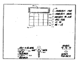
제1a도는 재폐쇄기 제어장치의 프론트 패널의 도면.1A is a view of the front panel of the recloser control device.
제 2 도는 재폐쇄기 제어장치의 기본적인 하드웨어의 블록선도.2 is a block diagram of the basic hardware of the recloser control device.
제 3 도는 본 발명의 일반화된 부품의 블록선도.3 is a block diagram of a generalized part of the present invention.
제 4a도는 제 3 도에 도시된 마이크로컴퓨터 회로기판과 개인(고유)기판의 블록선도.4A is a block diagram of the microcomputer circuit board and the personal (unique) board shown in FIG.
제 4b도는 제 3 도에 도시된 키보드와 LED표시장치의 블록선도.4b is a block diagram of the keyboard and LED display device shown in FIG.
제 4c도는 제 4a도에 도시된 비휘발성 메모리(EAROM)의 블록선도.4C is a block diagram of a nonvolatile memory (EAROM) shown in FIG. 4A.
제4d도는 제 4a도에 도시된 데이타 획득모듈의 블록선도.4d is a block diagram of the data acquisition module shown in FIG. 4a.
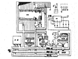
제5a도, 제 5aa도 및 제5b도 내지 제5h도는 제 3 도에 도시된 하드웨어 부품의 개략선도.5A, 5A, and 5B-5H are schematic diagrams of the hardware components shown in FIG.
제 6 도는 제어장치의 부품과 재폐쇄기 사이의 관계에 관련된 정부를 결합하는 재폐쇄기 제어장치의 배선도.6 is a wiring diagram of a recloser control device incorporating a government relating to the relationship between the components of the control device and the recloser.
제 7 도는 인터럽트 조정기 루틴(프로그램)의 흐름도.7 is a flowchart of an interrupt handler routine (program).
제 8 도, 제 9 도 및 제10도는 재폐쇄기 포어그라운드(fore ground)루틴의 흐름도.8, 9 and 10 are flow charts of the recloser foreground ground routine.
제11도는 트립 폐쇄루틴의 흐름도.11 is a flowchart of a trip closure routine.
제12도는 MERTOS 작동 시스템으로 구성된 여러 소프트웨어 모듈 및 정보처리에 사용된 프로그램의 여러 소프트웨어 모듈의 도면.12 is a diagram of several software modules comprised of a MERTOS operating system and several software modules of a program used for information processing.
제13도는 제12도의 보존관리 모듈에 포함된 재시작 및 포어그라운드 루틴의 흐름도.13 is a flowchart of restart and foreground routines included in the maintenance module of FIG.
제14a도는 제12도에 도시된 여러 모듈에 포함된 미들그라운드(middle ground)루틴의 흐름도.FIG. 14A is a flowchart of a middle ground routine included in the various modules shown in FIG. 12. FIG.
제14b도는 제14a도의 타스크 큐(task queue)블록에 포함된 정부를 순서적으로 처리하는 흐름도.FIG. 14B is a flowchart for sequentially processing the government included in the task queue block of FIG. 14A. FIG.
제14c도는 제14b도의 단기(short time)큐 블록을 확대 표시한 흐름도.FIG. 14C is an enlarged flowchart of the short time queue block of FIG. 14B. FIG.
제14d도는 제14a도의 실행 플래그 타스크 블록을 확대 표시한 프름도.FIG. 14D is an enlarged view of the execution flag task block of FIG. 14A. FIG.
제15도는 제12도에 도시된 개인 기판의 확대도.FIG. 15 is an enlarged view of the personal substrate shown in FIG.
제16도는 전력 공급기판에 개략선도.16 is a schematic diagram of a power supply substrate.
제17도는 재폐쇄기와 제어장치의 프론트 패널사이에 여러가지의 내부 접속도면.17 shows various internal connections between the recloser and the control panel front panel.
* 도면의 주요부분에 대한 부호의 설명* Explanation of symbols for main parts of the drawings
10 : 재폐쇄기 제어장치 12 : 재폐쇄기10: recloser control device 12: recloser
14 : LED 표시장치 30 : 피스톨 그림 스위치14
32 : 접지 트립 블록 스위치 34 : 재폐쇄 스위치32: ground trip block switch 34: re-close switch
76 : 트립 캐패시터 80 : 직류-직류 변환기76: trip capacitor 80: DC-DC converter
82 : 전력 공급 제어장치82: power supply control device
과거 수백년에 걸쳐 전자기술은 5번의 극적인 도약이 있었으며, 최초 4번의 도약은 전구, 전자관(진공관), 트랜지스터와, 집적회로이고, 가장 최근의 획기적인 도약은 1970년대와 1980년대에 마이크로프로세서의 출현을 의미한다. 마이크로프로세서와 그에 관련된 기억장치 및 인터페이스 부품으로 단 20년전의 실내 크기 컴퓨터와같은 성능이 있는 비교적 그 크기가 작은 디지탈 장치인 마이크로컴퓨터를 만들수 있게 되었다. 이러한 마이크로컴퓨터는 전자오락기, 계산기, 초단파 오븐기 및 POS(point of sale) 단말기로부터 교통신호등, 자동 점화 제어기, 복사제어기 및 우주선에 이르기까지 거의 무한정한 응용되어지고 있으며, 또한 산업로보트를 포함한 자동처리 제어분야의 발전에 있어 중요한 역할을 하고 있다. 그러나, 전력송전 및 배선장치에 있어서, 마이크로프로세서 응용이 거의 없으며, 특히, 전력장치에서 사용되는 보호 및 작동장치의 "자동화"제어부에 대한 응용은 거의 전무하다. 마이크로프로세서의 출현은 이러한 제어부를 구성할 수 있도록 기술적인 영역을 넓혀줄 수 있다.Over the past hundred years, electronic technology has made five dramatic leaps, the first four leaps being light bulbs, electron tubes, transistors, and integrated circuits, and the most recent breakthrough is the emergence of microprocessors in the 1970s and 1980s. it means. The microprocessor and its associated storage and interface components have made it possible to build a microcomputer, a relatively small digital device that has the same performance as a room-size computer just 20 years ago. These microcomputers have been applied in almost unlimited applications from electronic entertainment machines, calculators, microwave ovens and point of sale terminals to traffic lights, automatic ignition controllers, radiation controllers and spacecraft. It plays an important role in the development of the field. However, in power transmission and wiring apparatus, there are few microprocessor applications, and in particular, there are almost no applications for "automation" control units of protection and operating devices used in power apparatus. The advent of microprocessors can broaden the technical scope to configure such controls.
마이크로프로세서를 기초로하는 제어장치는 경제적으로 제조될 수 있었던 이전의 제어장치의 기능을 수행하고, 과거에 경제적인거나 기술적으로 수행할 수 없었던 기능을 수행할 수 있다.Controls based on microprocessors can perform the functions of previous controls that could be economically manufactured and perform functions that were not economically or technically feasible in the past.
재폐쇄기(Recloser)는 전력선에 삽입되어 전력배전장치를 보호한다. 전력배전선에 최대 던점은 그들에게 허용되는 도전범위에서만 퓨즈가 끊어지고 순간적인 속성과, 그 충분한 크기를 가져야 한다는 것이다. 배전장치에 퓨즈가 끊어졌을때, 수리공을 보내어 이를 교체해댜 하므로 어느정도의 비용을 감수했어야 했다. 재폐쇄기의 기본적인 기능은 퓨즈를 보호하는데 있으며, 일반적으로 퓨즈를 보호하기 위해서는 도전 전류의 피이크치를 검출하고, 퓨즈가 끊어지기 전에 재폐쇄기를 개방 또는 트립(trip)에의해 전류흐름을 차단하므로서 이루어진다. 그 다음 일정한 시간이 지난후 재폐쇄기는 배전장치에 전력을 회복시키도록 폐쇄되며, 다음의 고장(fault)이 감지될때까지 폐쇄상태로 있는다. 퓨즈가 끊어져 전류를 차단하는 속도는 퓨즈소자의 열적 가열의 함수이다. 열적가열의 속도는 고장에 의하여 발생된 전력에 대하여 비례하고, 각각의 퓨즈는 누전을 차단하는데 요구되는 시간간격을 나타내는 시간전류특성을 가진다. 일반적으로, 시간간격은 실효치(rms)에 역비례하며, 바람직한것은 보호된 퓨즈가 끊어지기 전에, 재폐쇄기가 사실상 일지적인 누전을 확실히 차단하도록 퓨즈와 함께 재폐쇄기를 조정하는것이 바람직하다. 이는 일반적으로, 누전의 피이크치를 검출하여 실효지에 접근시키므로서 수행될 수 있다.A recloser is inserted into the power line to protect the power distribution device. The biggest drawback to power distribution lines is that the fuses blow only within the range of their permissible conductivity and must have instantaneous properties and sufficient size. When the fuses were blown, they had to be repaired by sending a repairman to replace them. The basic function of the recloser is to protect the fuse, which is typically accomplished by detecting the peak of the conductive current and blocking the current flow by opening or tripping the recloser before the fuse is blown. After a certain period of time, the recloser is then closed to restore power to the power distribution unit and remains closed until the next fault is detected. The rate at which the fuse blows to cut off the current is a function of the thermal heating of the fuse element. The rate of thermal heating is proportional to the power generated by the failure, and each fuse has a time-current characteristic that represents the time interval required to shut off a short circuit. In general, the time interval is inversely proportional to the rms, and it is desirable to adjust the recloser with the fuse to ensure that the recloser virtually prevents a short circuit before the protected fuse is blown. This can generally be done by detecting the peak of a short circuit and approaching the effective area.
또한 전력배선에서 발생하는 모든 누전이 배선에 대해 순간적으로 떨어지는 브랜치(branch)에 의해 발생될 수 있는 바와같은 일시적인 것이 아님을 알고 있다. 몇가지 누전은 배선이 접지에 떨어져 닿게 되므로 발생되는 것과 같은 내구성으로 인해 발생될 수 있다. 결론적으로, 재폐쇄기는 록킹(locking)이 개방되기전의 단기내에 제한된 여러시간동안만 트립될 수 있도록 구성된다. 이를 수행할 수 없다면, 재폐쇄기는 퓨즈가 끊어질때까지 가동되어 보호하고자 하는 여러개의 퓨즈는 어떠한 경우라도 끊어지게 된다. 누전의 어느정도 크기에 있어서 시간 전류특성에 따르는 것보다 다소 배선을 보호하기 위해 순간적으로 재폐쇄기가 개방되도록 하는 것은 바람직한 것이다. 중간 레벨에서는 전력배선에 관한한 제한된 기간동안 누전을 허용하고, 이 누전이 퓨즈를 개방시키도록 하거나 끊어지게 하는것이 바람직하다.It is also known that not all short circuits occurring in power wiring are temporary, as can be caused by branches that fall momentarily on the wiring. Some short circuits can be caused by the same durability that occurs because the wiring touches the ground. In conclusion, the recloser is configured to trip only for a limited number of hours in the short term before the locking is opened. If this cannot be done, the recloser will run until the fuse blows, causing the multiple fuses to be protected to be blown in any case. It is desirable to allow the recloser to open instantaneously to protect the wiring rather than to follow the time-current characteristics in the magnitude of the leakage. At an intermediate level, it is desirable to allow a short circuit for a limited time as far as power wiring is concerned, and to allow the short circuit to open or blow the fuse.
여러가지 재폐쇄기는 이러한 목적을 이룰 수 있는 시간-전류특성을 가진다. 전형적으로, 재폐쇄기는 빠른시간 전류특성에 따르는 두가지의 단락 또는 트립작동이 허용되며, 록킹개방 또는 아웃전에 느린시간 전류특성에 따른 두가지 부가의 단락 작동을 한다.Many reclosers have time-current characteristics that can accomplish this purpose. Typically, the recloser allows two short or trip operations with fast time current characteristics and two additional short operations with slow time current characteristics before opening or out of locking.
마이크로프로세서를 기초로한 재폐쇄기 제어장치를 구성하는데 있어서의 장점은 여러가지 있는데 상기로부터 잘 알 수 있다. 예전에는 수행될 수 없었던 주된 이유는 마이크로프로세서를 기초로한 마이크로컴퓨터가 재폐쇄기 같은 전력배선 제어장치를 좋지 못한 환격에서 신뢰성있게 작동을 시킬 수 없는 비교적 저전력, 저전압, 저절류장치이기 때문이다.There are many advantages in constructing a recloser control device based on a microprocessor, which can be seen from the above. The main reason that could not be performed in the past is that microprocessor-based microcomputers are relatively low-power, low-voltage, low-flow devices that cannot reliably operate power wiring controls, such as reclosers, at poor ratings.
여러가지 전력제어장치 설계조건의 유사성을 이용함에 따라, 일련의 마이크로프로세서를 기초로한 모듈은 여러가지 전력배선 및 제어장치 응용에 있어 "빌딩블록(building blocks)"설계로 사용될 수 있도록 구성될 수 있다. 이러한 개념은 현재 및 미래의 제어장치 분야에서 요구되는 마이크로프로세서의 효용과 유연성을 극대화시킬 수 있다. 이러한 모듈의 다른 해결방법은 작동자의 숙련기간을 줄이도록 종래 장치와 유사한 방식으로 기능을 하는 제어패널, 좋지못한 외적 환격에서도 신뢰성 있게 작동시킬 수 있는 공통설계와 공통적인 수리기술에 있다.By taking advantage of the similarity of the various power controller design conditions, a series of microprocessor based modules can be configured to be used in "building blocks" designs for various power wiring and control applications. This concept can maximize the utility and flexibility of microprocessors required in today's and tomorrow's control applications. Another solution to these modules is a control panel that functions in a manner similar to conventional devices to reduce operator skill, common design and common repair techniques that can reliably operate in poor external environments.
이외에도 마이크로프로세서 전력제어장치에서 모듈개념을 이용하는데에 여러가지 장점이 있으며, 이들의 여러가지 유리한 작동 특징은 수리기술을 단순화하고, 프로그램 가능한 계획에 따라 원격통신 능력 및 "감시(watch dog)타이머로 구성되어 있는 여러 제어장치에 자동적으로 결합되어 있다. 또한, 모든 프론트 패널은 종래 장치와 유사한 방식으로 작동되며, 수리기술 및 장비는 제어장치가 공통적으로 구성되므로 그 수리시간을 최소로 한다. 최대의 소프트웨어 신뢰성은 새로운 작동장치를 사용하므로 보장된다. 모든 모듈은 결합되기 전에 철저하게 시험될 수 있고, 제조에 있어 공통적인 회로기판을 사용하므로 그 신뢰성을 최대로 하는 동시에 그 비용을 최소로 줄일 수 있다.In addition, there are several advantages to using the module concept in microprocessor power controllers, and their many advantageous operating features simplify the repair technique and consist of telecommunication capability and "watch dog timers" according to a programmable scheme. In addition, all front panels operate in a manner similar to conventional ones, and the repair techniques and equipment minimize the repair time since the controls are commonly configured. Is guaranteed by the use of new actuators: all modules can be thoroughly tested before they are combined, and common circuit boards are used in manufacturing to maximize their reliability and reduce their costs to a minimum.
마이크로프로세서를 기초로 한 제어장치는 작동자의 상상력 및 재능에 의하여서만 제한된 응용 및 장점으로 절력제어 장치에 있어서 새로운 차원을 전개한다.Microprocessor-based controls take a new dimension in power control devices with applications and advantages limited only by the imagination and talent of the operator.
마이크로프로세서를 기초로한 재폐쇄기 제어장치는 보호하고자 하는 전력선과 함께 전류를 검출하고, 비례입력 아날로그 신호를 멀티플렉스하며, 아날로그 신호를 부품 비용을 절약하기 위해 표준화하는 입력회로와, 그에 연결된 아날로그 디지탈 변환기가 입력신호를 디자탈화하도록 하는 샘플 홀드회로도 구성되어 있다. 마이크로프로세서 및 그에 연결된 기억장치 및 인터페이싱 성분으로 구성된 마이크로컴퓨터는 재폐쇄기 제어장치에서 사용되어 그의 제어를 위한 기본적인 필요에 따라 적당한 방법으로 입력신호를 처리하고 이전에 이를 수 없었던 새로운 기능을 수행한다. 전력을 제어장치의 다른 부품에 선택적으로 공급하고, 보호선이 차단될때 전력을 공급하게 하는 전력저장장치로 구성시킨 전력원은 이 제어장치에 설치된다. 상기 제어자아치는 전력이 차단될때 변경 가능한 기본적인 정보를 보호하는 프로그램 가능한 비휘발성 메모리로 구성되어 있다. 제어장치의 2차 과전류는 마이크로컴퓨터가 재폐쇄기의 트립작동 수행기능을 억지할때, 마이크로컴퓨터에 관계없이 동작한다. 보호입력 회로망은 전력배선장치의 좋지못한 환경으로부터 제어장치의 저전력 소자를 보호하며, 스케일링 수단(scaling means)은 마이크로컴퓨터와 결합된 회로가 정밀도가 요구되는 곳에서 입력신호 크기의 범위에 보다 더 정확히 작동하도록 하는데 사용되며, 제어장치가 입력신호의 넓은 범위에 걸쳐 제한된 수의 부품에 의하여 정확하게 작동하도록 하는데 사용된다.The microprocessor-based recloser control unit detects current with the power line to be protected, multiplexes the proportional input analog signal, and standardizes the analog signal to reduce component costs, and the analog digital connected to it. A sample hold circuit is also configured to allow the converter to dedigitize the input signal. A microcomputer, composed of a microprocessor and its associated storage and interfacing components, is used in a recloser control unit to process input signals in a manner appropriate to the basic needs for their control and to perform new functions not previously possible. A power source consisting of a power storage device which selectively supplies power to other components of the control device and supplies power when the protective wire is cut off is installed in the control device. The controller arch is comprised of a programmable non-volatile memory that protects basic information that can be changed when power is interrupted. The secondary overcurrent of the control unit operates regardless of the microcomputer when the microcomputer inhibits the reclosing function of the trip operation. The protection input network protects the low power elements of the control unit from the unfavorable environment of the power wiring device, and the scaling means is more precisely in the range of the input signal size where the circuit combined with the microcomputer requires precision. It is used to make it work, and it is used to make the control work correctly by a limited number of parts over a wide range of input signals.
마이크로컴퓨터 설계에 대한 본 발명의 주요한 점은 하드웨어 및 소프트웨어 설계의 필요조건을 모든 분야에 응용 가능한 공통적인 모듈로 세분화하여 여러가지 전력제어장치의 유사성을 이용하는데 있다. 이들 모듈이 설계되고 개발되는 경우 이들은 한 셋트이 재사용 가능한 "빌딩블록"으로 형성될 수 있다. 그 다음 이들 모듈은 특정제어장치를 위한 기초를 이룰 수 있도록 결합될 수 있다. 마이크로프로세서 제어장치 구성은 두가지 기본적인 설계분야가 있는데, 집적회로, 저항, 캐패시터, 표시장치, 스위치등과 같은 물리적인 소자를 한번 구성되면 쉽게 변화시킬 수 없기 때문에 "하드웨어"라 한다.The main point of the present invention for microcomputer design is to use the similarity of various power control devices by subdividing the requirements of hardware and software design into common modules applicable to all fields. When these modules are designed and developed, they can be formed into a "building block" in which one set is reusable. These modules can then be combined to form the basis for a particular control device. There are two basic design areas for microprocessor controllers, which are referred to as "hardware" because they cannot be easily changed once the physical components, such as integrated circuits, resistors, capacitors, displays, and switches, are configured.
마이크로컴퓨터의 제 2 의 기본적인 설계분야는 물리적인 것이 아닌 연산, 컴퓨터 프로그램 및 자료들은 포함하는 것으로, 이는 쉽게 변경 가능하기 때문에 "소프트웨어"라고 한다.The second fundamental design area of microcomputers involves computations, computer programs and materials that are not physical, which is called "software" because they are easily modifiable.
제 1 도에는 대표적인 재폐쇄기(12)와 결합된 본 발명의 재폐쇄기 제어장치(10)가 도시되어 있다.1 shows a
제1a도는 재폐쇄기 제어장치(10)의 프론트 패널을 확대한 도면이다 상기 패널은 정보를 나타내기 위한 6개의 디지트 LED표시장치(14)로 구성되어 있으며, 또한, 정보의 입려과 7개의 램프로 나타내는 키보드(16)가 구성되어 있다. 상기 램프는 재폐쇄기 개방(18), 재폐쇄기 폐쇄(20), 제어 록-아웃(22)(lock-out), 제어 최소화 트립(24), 제어고장(26) 및 록-인(28)에 대한 상태정보를 나타낸다. 피스톨 그립(pistol grip)스위치(30)는 트립 또는 폐쇄위치로 이동된 후 중심의 중립위치로 돌아오도록 스프링로드된 제어장치용 마스터 보조수동장치(master override)이다. 스위치 작동기가 스프링 로드되어 있는 동안 피스톨 그립 스위치(30)와 연결된 몇개의 접촉부는 그립이 중립위치로 돌아올때까지 최종 중립위치에 선택적으로 유지된다. 접지 트립 블록스위치(32)가 도면보다 상단 위치에 있을때에는 접지고장으로 인하여 트립을 방해한다. 접지트립 블록스위치(32)가 도면보다 하단의 정상위치에 있을때, 재폐쇄기 제어장치(10)는 접지고장이 발생할때 재폐쇄기를 트립한다. 접지트립 블록스위치(32)의 아래에는 그 스위치가 상단위치에 있을때 재폐쇄스위치(34)는 재폐쇄를 방해하지만, 재폐쇄스위치(34)가 하단위치에 위치시킬때 정상적으로 재폐쇄기 제어장치(10)를 작동하도록 한다.FIG. 1A is an enlarged view of the front panel of the
트립 및 폐쇄코일, 재폐쇄기 스위치 내부 접속 및 재폐쇄기 인터페이스 기판의 관계가 제17도에 도시되어 있다. 피스톨 그립 스위치(30)에 연결된 접촉부는 두가지의 분명한 유형이 있다. 와이퍼(702 및 704)와 연결된 것들은 순간 접촉부이고, 와이퍼(706)와 연결된 것들은 유도(drag)접촉부이다. 유도 접촉바아(708)는 피스톨 그립 스위치(30)가 폐쇄위치로 되면서 중간위치로 전환할때 와이퍼(706)와 폐쇄접촉부(C)사이의 위치에만 유지된다.The relationship between trip and closure coils, recloser switch internal connections and recloser interface substrates is shown in FIG. There are two distinct types of contacts connected to the
N접촉부는 피스톨 그립 스위치(30)가 스프링 로드되어 중립 위치로 되돌아올때 와이퍼(702), 와이퍼(704) 및 와이퍼(706)와 접촉되는 접촉부를 나타낸다. T접촉부는 스위치가 C접촉부와 접촉하도록 트립위치로 돌려졌을때 와이퍼의 위치를 나타내는데, 이때 스위치는 폐쇄위치로 돌려진다. 유도접촉바아(708)는 피스톨 그립 스위치(30)가 폐쇄위치로 돌려진 후 N접촉부와 C접촉부 사이에 접촉을 유지한다. 유도접촉바아(708)는 T접촉부와 와이퍼(706)와 연결된 N접촉부 사이에서는 접촉상태로 유지되지 않는다.The N contact indicates a contact that comes into contact with the wiper 702, the wiper 704 and the wiper 706 when the
트립코일(710)과 폐쇄코일(712) 각각은 재폐쇄기 제어장치(10)로부터 그들의 전압원과 직렬로 내부 접속되는 접촉부를 가지고 있다. 동일한 내부 접속 접촉부(52/A)는 재폐쇄기에 의하여 기계적으로 작동되는 스위치 접촉부이며, 재폐쇄기의 차단 접촉부로써 동일 상태로 유지된다. 그와 마주보고 있는 내부 접속접촉부(52/B)도 마찬가지로 재폐쇄기의 차단 접촉부에 의하여 반대상태로 있는다. 핸들 접촉부(714)는 재폐쇄기에 의하여 작동되지 않으나 재폐쇄기 차단 접촉부를 강제로 개방되게 하는 핸들에 의하여 개방되는 스위치 접촉부이다.Each of the trip coil 710 and the closing coil 712 has contacts that are internally connected in series with their voltage source from the
피스톨 그립 스위치(30)가 트립위치로 돌아왔을때, 트립코일(710)은 재폐쇄기 차단 접촉부를 개방하고, 트립 제어신호를 재폐쇄기 인터페이스 기판에 전송하도록 에너지를 가한다. 이러한 일이 수행됨에 따라 유도접촉바아(708)는 그에 연결된 N 및 C접촉부 사이에 연결부를 개방시키는데, 이는 재폐쇄기 인터페이스 기판으로 가는 페쇄제어신호 및 접지로 가는 폐쇄코일(172) 경로를 차단한다. 재폐쇄기가 그의 차단 접축부를 개방시킴에 따라 반대의 내부 접속 접축부(52/B)는 폐쇄된다. 피스톨 그립 스위치(30)가 폐쇄위치로 돌아왔을때 유도접촉바아(708)는 그에 연결된 N접촉부 및 C접촉부 사이를 연결시키며, 이 경우 피스톨 그립 스위치(30)가 트립위치로 돌아올때까지 유지된다. 와이퍼(704)는 재폐쇄기 인터페이스 기판까지 피스톨 그립 스위치 폐쇄신호를 발생시키도로 C접촉부와 접촉한다. 유사한 방식으로 피스톨 그립 스위치(30)가 트립 위치로 돌아왔을때 와이퍼(704)는 피스톨 그립 스위치 트립신호를 재패쇄기 인터페이스 기판에 전송한다. 트립 코일(710)에 에너지를 가할 때마다, 트립 모니터 신호를 재폐쇄기 인터페이스 기판까지 전송한다. 마찬가지로, 폐쇄코일(712)에 에너지를 가할때, 폐쇄 모니터 신호를 재폐쇄기 인터페이스 기판까지 전송한다. 제5H도에 도시된 바와같이, 전압이 마이크로컴퓨터용 디지탈 부품을 대하여 보통 5볼트 전원전압 이상의 전압과 관련된 신호를 광학적으로 분리한다.When the
키보트(16)에 있어서, 변경 또는 표시하고자 원하는 정보는 제13도에 도시된 것처럼 키보드이 키이에 의하여 직접 분류된다. 이러한 일은 제1 및 제 2 시간 전류특성, 최소트립과 LED표시장치(14)를 위한 온/오프키이로 수행된다. 또한, 제 1 시간 전류특성에 따른 여러가지 작동, 록-아웃시키기 위한 여러가지 작동과, 여러번의 트립이 트립 카운터에 얼마나 오래동안 기억되고, 정상상태에서 유지될 것인가를 결정하는 리셋트 간격으로 수행된다. 또한, 연속표시기와, 재폐쇄기가 개방상태로 있는 간격을 결정하는 재폐쇄 시간으로 수행된다. 카운터키이는 여러번의 트립을 표시한다,. 위상 및 접지키이는 개별적인 위상의 특성을 표시한다. 키이의 기능은 다른 명령 정보의 입력을 허용하며, 그 키이의 기능은 명령 정보가 함수 코드 번호에 의해 선택되도록 한다.In the
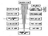
제 3 도는 하드웨어 모듈을 사용하여 이들이 일반화된 전력장치가 어떻게 구성되어 있는가를 나타낸다.3 shows how power devices are constructed using generalized hardware modules.
이들 모듈은 세가지 방법으로 사용되어 특정전력 장치제어를 수행한다. 예를 들면, 버스 버퍼 모듈은(48)은 아주 적은 수정만으로 모든 제어장치에서 사용될 수 있다 몇가지 모듈은 모든 제어장치를 위한 기초가 되는 공통 마이크로컴퓨터 회로기판을 형성하도록 결합될 수 있다.These modules are used in three ways to perform specific power device control. For example, the bus buffer module 48 can be used in all controls with very few modifications. Several modules can be combined to form a common microcomputer circuit board that is the basis for all controls.
최종적으로 다른 모듈은 각각의 특정한 제어장치에 맞는 "개인(personality)"회로기판을 형성하도록 결합된다.Finally, the other modules are combined to form a "personality" circuit board for each particular control device.
개인 회로 기판은 제어하고자 하는장치와 마이크로컴퓨터 사이에 소정 입력 및 출력 인터페이싱(접속부)으로써 다른 부품 가운데 설치된다. 이 인터페이싱의 가장 중요한기능 가운데 하나는 회로 부품에 대하여 거짓 응답 또는손상을 일으키는 제어 장치의 민감한 지역의 영향으로 인해 원하지 않는 신호와 전자기 간섭(EMI)을 방지하기 위해 입력 및 출력선을 보호하는데 있다.The personal circuit board is installed among other components with predetermined input and output interfacing (connections) between the device to be controlled and the microcomputer. One of the most important functions of this interfacing is to protect the input and output lines to prevent unwanted signals and electromagnetic interference (EMI) due to the influence of sensitive areas on the control unit that cause false responses or damage to circuit components.
마이크로프로세서 모듈(38)은 제어 장치의 여러가지 연산 및 논리 기능을 수행하는 회로 소자이다. 이 모듈은 이용 가능하고, 특히 전력 장치 제어 응용에 적합한 최대 성능의 마이크로프로세서중의 하나로 설계되다. 특히, 모든 소정의 논리 회로뿐만 아니라 용이하게 수리할 수 있는 가능성도 포함하고 있다.The
판독/기록 메모리 모듈(RAM)(40)은주로데테이타를 일시적으로 기억하는데 사용된다. 예를들어,재폐쇄기에서 이 정보는 선 전류 크기로 기억된다.The read / write memory module (RAM) 40 is mainly used to temporarily store data. For example, in a recloser this information is stored as the line current magnitude.
타이머 모듈(42)은 동시발생 보호 장치에서의 본직적인 요소중의 하나인 60헬즈 전후로한 주파수 모니터로 구성된다. 전력 배선 장치에서의 고장 또는 연속적인 고장이 상당히 큰 누전을 일으키는 경우,발전기의 안정성을 잃게 되는데, 이러한 경우 이 발전기사의 부하가 이 장치의 안정성이 회복될만큼 커야 한다. 사아기는 교류 전류를 변화시키는 주파수가 발생할때 가장 심각한 경우이다. 타이머 모듈은 재폐쇄기를 트립하여 상기 일을 발생될때 그의 부하를 크게 한다. 또한, 이러한 모듈은 부하의 흐름과 고장 결과 데이타를 위한 현재 정보를 제공한다.The
프론트 패널 보듈(44)은 프론트 패널 발광 다이오드(LED)표시 장치(14)및 키보드(16)를 마이크로 컴퓨터(제1a도 참조)에 연결하기 위해 사용된다.The
마이크로컴퓨터는 다중 스위치와 사용자가 선택하는 제어 설정을 반도체 기억 장치에 기억시키므로 부품으로써의 플러그에 대한 필요성을 배제한다. 상기 사용자 선택은 연산형 키보드(16)에 의하여 이루어진다. 현지 설정의 질의는 기능 키이를 누르거나 또는 기능 코드를 입력시켜서 LED표시 장치(14)(제1a도)상의 설정 상태를 결정하므로 수행될 수 있다. 새로운 설정의 엔트리(enyry)는 작동자가 기밀(security)코드를 제 1엔터로 부가 또는 수정하도록 수식되었는가를 검증하여야 한다. 기밀 코드가 클리어되었을때, 사용자는 새로운 설정을 할 수 있다.The microcomputer stores the multiple switches and the user-selected control settings in the semiconductor memory device, thereby eliminating the need for plugs as components. The user selection is made by
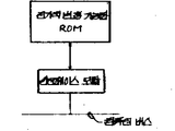
프론트 패널 모듈의 작동은 특히, 표시 특성의 분야에서 최대 유연성으로 제어되는 수프트웨어에 의하여 제어된다. 모든 제어 장치 설계에 이러한 모듈을 사용하므로 프론트 패널 모듈 설계 및 작동이 유사하다. 판독 전용 메모리 수단(46)은 가급적 용이한 수정을 위하여 전기적으로 프로그램 가능하고, 프로그램 정보를 기억하는데 사용된다. 예를들면, 재폐쇄기 제어 장치에서, 이 모듈은 여러가지 시간-전류 특성 커브로 아루어진 명령 정보를 포함하고 있다.The operation of the front panel module is controlled, in particular, by the suitably controlled software in the field of display characteristics. The design and operation of the front panel module is similar because these modules are used for all control device designs. The read only memory means 46 is electrically programmable for easy modification, and is used to store program information. For example, in a recloser control device, this module contains command information comprised of various time-current characteristic curves.
버스 버퍼 모듈(48)은 특정 제어 장치 설계에서 사용된 여러개의 모듈을 확대시키는데 사용된다. 버스 버퍼 모듈의 사용에 의하여 거의 제한된 수의 모듈을 제어 장치내에 구성할 수 있다.The bus buffer module 48 is used to expand the number of modules used in a particular control device design. The use of a bus buffer module allows the configuration of an almost limited number of modules in the control device.
감시 타이머 모듈(50)은 이 제어 장치가 순간적인 고장을 일으켰을 경우라도 확실한 제어 작동을 하도록 하는데 사용된다. 그후, "감시"회로는 그 오차를 분석하여 교정하는 마이크로컴퓨터의 작동을 차단한다. 큭히 감시 타이머 모듈(50)은 출력이 전송되지 못하도록 입력펄스의 정상 스트림을 필요로 하는 부재 펄스 검출기 (missing pules detector)로 구성되어 있다. 적당한 프로그램 순서가 분실되어 시스템이 차단된 경우, 감시장치 타이머는 컴퓨터를 강제로 재설정 하도록 "타임 아웃(time out)"된다. 제5e도에 도시된 바와 같이, 감시장치 회로는 마이크로컴퓨터에 의하여 장규적으로 재설정 되지 않을때 마이크로컴퓨터의 작동을 차단시킬 수 있는 두개의 재설정 가능한 R-C타이머로 구성되어 있다.실제로, 이는 소프트웨어 데이타 전송시에 에러를 감지 하도록 작용하여 에러 검출할때, 제 13도의 흐름도와 같이 재시작 프로그램 모듈을 작동시킨다.The watchdog timer module 50 is used to ensure reliable control operation even if this control device has caused a momentary failure. The "monitor" circuit then shuts down the operation of the microcomputer to analyze and correct the error. Often, the watchdog timer module 50 is comprised of a missing pules detector that requires a steady stream of input pulses to prevent the output from being transmitted. If the proper program sequence is lost and the system shuts down, the watchdog timer is "timed out" to force the computer to reset. As shown in Figure 5e, the supervisor circuit consists of two resettable RC timers that can shut down the operation of the microcomputer when it is not normally reset by the microcomputer. When the error is detected by acting to detect the error at the time, the restart program module is operated as shown in the flowchart of FIG.
개인 회로 기판(제3도)은 다음 것들로 구성되어 잇다. 판독/기록/세이브 메모리 모듈(EAROM)(52)은 전력을 공급받지 않고도 데이타를 기억하고 보유한다. 이는 전기적으로 변경할 수 있는 비휘발성 메모리이며, 바테리가 요구되지 않는다. 이 모듈은 설정, 기밀 코드, 직력의 수, 경과 데이타, 단축된 시간-전류 특성, 정상적인 기준치,순간적인 트립치, 소정 시간 전류 특성에 따른 작동의 수, 측정 및 작동을 위한 시간 간격을 기억하도록 하는데 사용된다.The personal circuit board (Figure 3) consists of the following: Read / write / save memory module (EAROM) 52 stores and holds data without being powered on. It is an electrically changeable non-volatile memory and no batteries are required. This module allows you to remember settings, airtight codes, number of series, history data, shortened time-current characteristics, normal reference values, instantaneous trips, number of operations according to a certain time current characteristic, time intervals for measurement and operation. It is used to
직렬 통신 모듈(54)은 마이크로컴퓨터가 자동화된 배선 장치에 소요되는 다른 장치와 통신되도록 하는데, 이는 마이크로컴퓨터가 원격 조정될 수 있게 한다. 또한, 이 모듈은 대량 데이타(bulk data)를 어느정도의 시간이 지난 미래에 대해 분석하기 위하여 데이타 기록기에 덤프(dump)할 수 잇다. 재폐쇄기내에서, 이장치는 고장중 이거나 고장후의 전력 시스켐에 대한 여러가지 정보를 가긴 "고장 예상 지점 (fault foot print)"을 포함한다.The serial communication module 54 allows the microcomputer to communicate with other devices required for the automated wiring device, which allows the microcomputer to be remotely controlled. In addition, the module can dump bulk data to a data writer to analyze the future over some time. Within the recloser, the device includes a "fault foot print" with various information about the power system after or after a failure.
데이타 획득 모듈(56)은 전력 시스템 상태의 정보를 얻어 제어 장치의 내부 기능을 모니터 한다. 이는 두개의 모듈내에서 이루어진다. 하나의 모듈은 필요한 전력 시스템 상태 정보를 마이크로컴퓨터에 공급한다.The data acquisition module 56 obtains information of the power system status and monitors internal functions of the control device. This is done in two modules. One module supplies the microcomputer with the necessary power system status information.
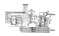
전력 시스템 제어 장치에 있어서, 상기 상태 정보는 일반적으로 위상, 점지 전류 및 전압 데이타로 이루어진다. 본발명의 재폐쇄기 제어 장치(10)에 있어서 데이타 획득 모듈은 제2도에 도시된 입력 회로와 데이타 획득부로 구성되어 잇다. 입력 회로는 저항(58)과 데이타 획득부의 상부에 있는 다이오드(60)로 구성되어 잇다. 저항(58)과 다이오드(60)는 멀티플렉서(62)에 의하여 전송되지 않는 입력을 크램프한다. 어느 한 입력이 전송될때, 이는 가상 접지 (virtual ground)에 효과적으로 크램프 된다. 데이타 획득부는 먼저 마이크로프로세서(38)의 제어레 따라 입력 신호를 멀티프러렉스하고, 그다음 프로그램 기능 타이머(42)가 가상 접지 입력 상태를 이용하도록 합산 증폭기(64)를 사용한다. 그후, 이 데이타 습득부는 제어 장치의 작동자에 의하여 입력될 수 있는 미리.선택된 정규화된 신호에 따라 멀티플렉서(62)에 의하여 전송된 입력 신호를 정규화한다. 정규화된 입력 신호의 출력을 샘플링 하고, 이들을 프로그램 가능 타이머 모듈(42)의 제어하에서 이미 선택된 기간동안 유지시키는 샘플 홀드 회도(66)는아날로그-디지탈 변환기(68)에 의해 디지탈화 된다. 마이크로컴퓨터는 제2의 테이타 획득 모듈을 바테리 및 전력원과 같이 제어 장치의 여러가지 내부 기능을 "자체-모니터(self-moiter)"하도록 한다.In a power system control apparatus, the state information generally consists of phase, point current and voltage data. In the
인터페이스 모듈(70)은 마이크로컴퓨터가 제어장치의 다른 부품에 연결되게 하는데 사용된다. 예를들면, 재폐쇄기 제어 장치에서 마이크로컴퓨터는 재폐쇄기 스위치 (34)및접지 트립 블록 스위치(32)로부터의 입력과, 다른 표시 장치 및 제 1a도의 패널상에 피스톨 그립 스위치(30)같은 제어 장치 입력을 필요로 한다. 부가적으로, 재폐쇄기 제어 장치는 트립 코일 회로, 폐쇄 코일 회로, 여러가지 표시기로 출력이 제공되어야 한다. 재폐쇄기의 원격 폐쇄,트립(352),록-아웃(354),원격 최소 트립 멀티플라이어 (356)와 재폐쇄 블록(358)으로 이루어진 몇가지 제어 기능은 제5d도에 도시한 바와 같이 사용자의 계전 접촉 또는 전압 신호에 의하여 원격으로 작동될 수 있다.The interface module 70 is used to connect the microcomputer to other parts of the control device. For example, in the recloser control device, the microcomputer can control the input from the recloser switch 34 and the ground trip block switch 32 and other control devices such as the
마찬가지로, 이 제어 장치는 상태 정보를 계전기 접촉부를 가진 원격 위치까지 공급한다. 이러한 식으로 공급된 정보는 재폐쇄기 접촉 위치, 록-아웃 및고장 상태를 나타낸다. 이러한 능력은 전력 장치 보호에 적용시킬 수 있는 마이크로컴퓨터를 기초로한 제어 장치로써 수행될 수 있다.Likewise, the control device supplies status information to remote locations with relay contacts. The information supplied in this way indicates the recloser contact position, lock-out and failure status. This capability can be performed with microcomputer-based control devices that can be applied to power device protection.
또한, 재폐쇄기 제어 장치의 개인 회로 기판은 2차 과전류 트립 회로 (SOCT)(72)로 구성되어 있다. 이 SOCT(72)는 각각의 3상 전력선의 전류에 비례하는 입력 신호를 수신하며 제2도에 도시된 입력 회로와 같이 접지되어있다.In addition, the personal circuit board of the recloser control device is composed of a secondary overcurrent trip circuit (SOCT) 72. This
그러나, 이 SOCT(72)는 트립 신호를 발생시키는 의도 기능을 수행하도록한 마이크로컴퓨터의 신뢰성 있는 기능과는 무관하다. 감지된 전류가 고정된 2차 시간 전류특성을 초과했을때, 상기 특성에 따른 시간 간격의 경과후 트립 신호는 SOCT(72)를 마이크로컴퓨터에 의하여 작동시킬 경우 발생된다. 마이크로컴퓨터가 초기에 전력을 공급받거나, 에러 상태를 받을때는 전력 배선을 위하여 보호조치를 취할 수 있도록 신뢰성 있는 작동을 할 수 없다.However, this
또한 이후에 기술될 전력 기억 장치가 소모되는 경우에 연장된 선 중지(outage)의 상태하에서 마이크로컴퓨터는 신뢰성있는 작동을 기대할 수 없다. 이러한 상태하에서,SOCT(72)는 보호된 전력선에 대한 최소의 보호를 할 수 있으며, 이는 다른 방식으로는 마이크로컴퓨터에 의하여 정지된다.In addition, the microcomputer cannot expect reliable operation under extended outage conditions when the power storage device described later is consumed. Under this condition, the
전력 공급 모듈(전력원)(36)은 전력을 마이크로컴퓨터와 그에 연결된 부품에 공급한다. 재폐쇄기 제어 장치(10)의 경우에서, 이 모듈은 120볼트이 교류 전력원(74), 재폐쇄기를 트립할 수 있도록 하는데 충분한 크기의 트립 캐패시터(76), 재충전 시킬 수 있는 니켈-카드륨 바테리(78),직류-직류 변환기(80)및 제 6도에 도시된 전력 공급 제어 기판(82)으로 구성되어 있다. 트립캐패시터(76)와 바테리 (78)는전력 저장 수단이다. 고장 상태동안발생되는 것처럼,120볼트 전압의 교류 전력원의 일시적 고장에 따라, 제어 장치의 대기휴지(quiescent)필요성이 DC-DC변환기(80)를 경유하여 바테리에 의해 공급 될 것이다. 영구적인 고장 상태 이외의 모든 상태하에 있어서, 상기 방법은 일정 시간의 인터럽트 될 수 없는 기간동안 전력 공급을 할 수 있게 한다.심지어 영구적인 고장 상태에서도, 직렬 통신 링크를 사용하므로, 마이크로컴퓨터 제어 장치는 가급적 절력원(36)과 바케리(78)를모니터 하고, 그다음 즉죽각적인교정 작동이 취해질 수 있도록 상기 상태 정보를 중앙 지국으로 전송한다. 결국,절력이 일정시간내에 회복되지 않는다면, 마이크로컴퓨터는 대기모드로 스스로 전력을 낮추어 바테리 (78)를 보존시키도록 최우선 순위 임무(제 13 참고)만을 수행한다.The power supply module (power source) 36 supplies power to the microcomputer and its components. In the case of the
결론적으로 마이크로컴퓨터에 따른 폐쇄는 바테리(78)가 완전히 방전되기 전에 발생한다. 이러한 상태하에서, SOCT(72)는 바테리(78)가 정상 전압으로 재충전 되기 전에 재폐쇄기(12) 트립 캐패시터(76)로 트립시킬 수 있다.In conclusion, the closure along the microcomputer occurs before the battery 78 is fully discharged. Under this condition,
제16도에 도시된전력 공급 제어 장치(82)의 일부인 전력 공급 모듈(36)은 마이크로프로세서(30)가 스위치된 24볼트 전압 공급원(84)과 스위치 되지 안은 24볼트 전압 공급원(86)에 의하여 점차적으로 전력이 떨어지게 하는 수단으로 구성되어 있다. 또한, 판독/기록/세이브 모듈(52)로 구성된 전기적으로 변경 가능한 판독전용 기억 장치(EAROM)를 변화시키는데 필요한 음의 28볼트 신호를 공급한다. 이 신호는 전압 이중 회로(90)내에 연결시킨 시간형 플립-플롭(88)을 사용한 제16도 회로에 의하여 공급된다. EAROM(52)의 변경은 제 3도에 도시된 직렬 통신 모듈(54)에 의하여 입력된 입력 키보드(16)및 원격 신호로 부터 명령에 응답하는 마이크로프로세서(38)의 제어에 따라 이루어진다. 전력 공급 제어 장치(82)는 대기 온도에 따라 변화하는 바테리를 소정의 속도로 충전하도록 온도 보상된다.The power supply module 36, which is part of the power
전력 공급 제어 장치의 스위칭 트랜지스터(92)는 전력 공급 제어 장치 (82)및 마이크로프로세서로 발생된 신호(96)를 공급하는 브리지 (94)의 출력 전압에 응답한다. 만일, 전압이 입력 브리지(93)에 공급되는 경우 트랜지스터(92)는연장된 전력 중지 기간동안 분배될 수 있는 부품에 24볼트를 공급한다. 이러한 전압을 공급하기 위해서, 마이크로프로세서는 스위칭 트랜지스터(96)를 오프시키는 신호(96)를 발생시킨다. 이러한 일은 마이크로프로세서(38)를 효과적으로 오프시키고, 전력 감소 기간이 끝난 후에 실행된다.The switching transistor 92 of the power supply control device is responsive to the output voltage of the bridge 94, which supplies the signal 96 generated by the power
상기 기술로부터, 이러한 설계 방법이 지그소우(jigsaw)퍼즐같이 평행하게 측으로 놓인 모듈 개락도에 의하여 만들어진 제어 장치의 "전체 개략도(imstant schematic)"의 임을 알수 있다. 따라서, 새로운 모듈이 이시스켐에 부가될 수 있으며, 이에 따라 기술을 진보시키거나 설계적 조건을 변경시킬 수 있다.From the above description, it can be seen that this design method is of the "imstant schematic" of the control device made by the module openings laid in parallel side like jigsaw puzzles. Thus, new modules can be added to ISISCHEM, thus allowing advances in technology or changing design conditions.
제1a도를 참고하면, 프론트 패널은 상단부와 하단부로 나누어진다. 상단부는 키보드(16)와 표시장치(14)로 구성되며, 하단부는 수동 작동을 위한 제어 장치로 구성되어 있다. 또한, 램프르 시험하는 표시 램프와 그에 관련된 스위치가 설치되어 있다. 프론트 패널의 상단부는 6개의 디지트 LED표시 장치(16), LED표시장치 상태표시기 및 16개의 버튼 키보드로 구성되어 잇다. LED 표시장치는 소정의 정보를 표시하기 위해 사용된다. LED상태 표시기는 재폐쇄기 개방(18), 재폐쇄기 폐쇄(20), 제어 장치 록-아웃(22),제어 장치 최소 트립(24), 제어 장치 고장 (26)및 제어 장치 록-인(28)등과 같은 정보를 나타낸다. 재폐쇄기에서 정규화 기준, 시간 전류 특성, 순간적인 트립치, 소정 시간 전류 특성에 따른 여러가지 작동을 위한 시간 간격은 모두 키보드(16)에 의하여 선택된다.Referring to Figure 1a, the front panel is divided into an upper end and a lower end. The upper part is composed of a
상시 스위치와 키보드을 사용함으로, 이 장치의 모든 작동은 명령 정보에 의하여 완전하게 제어될 수 있다. 본 발명의 재폐쇄기 제어 장치를 위한 전형적인 명령 정보는 재폐쇄기의 비교적 빠른 트립핑을 일으키는 위상 및 접지 전류를 위한 제1의 시간-전류 특성과, 고장 상태에서 비교적 오랫동나 폐쇄된 상태로 유지되게한 제어 장치에서 일어날 수 있는 위상 및 접지 전류에 대한 제2의 시간-전류 특성이다.By using the always-on switch and keyboard, all operations of the device can be completely controlled by command information. Typical command information for the recloser control device of the present invention allows the first time-current characteristic for phase and ground currents to cause relatively fast tripping of the recloser, and to remain relatively closed for a long time in a fault condition. Second time-current characteristic for phase and ground currents that may occur in the control device.
다른 명령 정보는 재폐쇄기 제어 장치에서 시간-전류 특성에 따라 시간 처리를 시작하는 위상 및 접지 전류에 대한 최소 트립 레벨, 위상 및접지 고장 상태하에록-아웃 되는 단락수와, 소정 시간 전류 특성이 이루어질 수 있는 시간들로 이루어진다. 또한, 명령 정보는 고장이 없는 상태에서 단락수를 기록하는 카운터가 정보를 보유하는 기간을 결정하느 리셋트 시간 간격, 재폐쇄기가 개방 상태로 유지되는시간을 결정하는 여러버늬 재폐쇄 간격과 주파수 매개 변수에 따른 오버(over)이다.The other command information includes the minimum trip level for the phase and ground currents that start time processing in accordance with the time-current characteristics in the recloser control device, the number of shorts that are locked out under the phase and ground fault conditions, and the predetermined time current characteristics. It is made up of hours. In addition, the command information includes reset time intervals that determine how long the counter that records the number of short-circuits in the absence of a fault hold information, multiple reclose intervals and frequency parameters that determine how long the recloser remains open. Over the variable.
부가의 명령 정보는 누전의 일정한 크기하에서 고정기간동안만 폐쇄 상태로 재폐쇄기를 유지되게 하는 고전류 상수 시간 특성, 재폐쇄기 트립 기능의 블록킹 및 인러쉬 상태(inrush condion)하에서 재폐쇄기 개방을 못하게 하도록 최소 트립레벨로 작동하는 인러쉬 값이다. 또한 이러한 기능은 최소트립 레멜을 멀티플라이 하거나 일정한 값으로 증가시키도록 마이크로컴퓨터를 단순 명령함으로써만 실행될 수 있다.Additional command information is required to ensure that the recloser remains closed for only a fixed period of time under a constant magnitude of leakage, to prevent recloser opening under blocking and inrush condion of the recloser trip function. An inrush value that acts as a trip level. In addition, this can only be done by simply instructing the microcomputer to multiply or increase the minimum trip level to a constant value.
또한 다른 매개변수는 연속 카운터의 위치, 제어 장치 및 재폐쇄기에서의 고장 상태, 또는 전류가 트립핑의 6싸이클내에서 인터럽트 되지 않는 경우에 록-인으로 인해 재폐쇄기상의 고장, 제어기의 전 수명에 걸쳐 여러번의 트립 작동을 기록하는 트립 카운터, 부하 전류, 바테리 및 충전 상태와 원격 상태 질의의 키보드를 사용하여 시험되거나 변경될 수 있다.Other parameters also include the position of the continuous counter, the fault condition in the control unit and the recloser, or the fault on the recloser due to lock-in if the current is not interrupted within six cycles of tripping, the life of the controller. It can be tested or changed using the keyboard of trip counter, load current, battery and charge status and remote status query to record multiple trip operations over time.
마이크로컴퓨터는 세개의 확실한 회로기판, 즉,제3도에 도시된 마이크로컴퓨터 회로 기판, 표시장치 기판과 개인 기판으로 구성되어 있다.공통 마이크로컴퓨터 회로 기판은제어 장치의 하드웨어의 심장부이다. 이 기판은 마이크로프세서 모듈(38)과 이의 작동에 밀접히 관련되는 부품들로 구성되어 있다. 작동 시스템은 물론 중앙 프로그램을 포함한 ROM(46)의 상기 기판상에 위치된다.The microcomputer consists of three reliable circuit boards, namely the microcomputer circuit board shown in FIG. 3, the display board and the personal board. The common microcomputer circuit board is the heart of the hardware of the control device. The substrate consists of a
표시 장치 기판은 공통 마이크로컴퓨터 회로기판과 결합 되며, 입력 키보드(16)와 출력 LED표시 장치로 구성되어 있어 작동자가 제어 장치로 "통신"하게 한다. 공통 마이크로컴퓨터 회로 기판 및 표시 장치 기판은 모든 전력 제어 장치에대하여 공통으로 사용하되, 다른 전력 마이크로컴퓨터로 구성된 제어 장치의 다른 전력 시스템에 사용된다. 다른 응용 분야에 변경시킬수 있는 주 장치는 소정 작용을 위한 정확한 프로그램을 수행하는 메모리와 개인 기판이다.The display device substrate is coupled to a common microcomputer circuit board and consists of an
개인기판은 특정 제어 장치에 대한 유일한 하드웨어로 구성되는데, 이 개인 기판은 아날로그 신호를 수신할 수 있으며, 그 수신된 신호의 디지탈 상태와, 여러가지 계전기 및 스위치의 상태로 공통 마이크로컴퓨터 회로 기판에 공급하는 EQROM(52)를 갖는다. 개인 기판의 주요 부푼은 제 4a도의 블록선도의 공통 마이크로컴퓨터 외측에 도시되어 있으며, 트립 회로(98)및 폐쇄 회로(100)를 제회한 제 4d도에 도시되어 있다.Personal boards consist of unique hardware for a particular control device, which can receive analog signals and supply them to a common microcomputer circuit board in the digital state of the received signals and in the state of various relays and switches. Has EQROM 52. The main bulge of the individual substrate is shown outside the common microcomputer of the block diagram of FIG. 4A, and in FIG. 4D above the trip circuit 98 and the
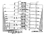
멀티플렉서(62)를 나타내는 제5aaa도에 도시된 저항기(58)및 다이오드(60)의 회로는 멀티플렉서(62)및 다른 저전력 소자를 고장 또는 오차를 일으킬 수 있는 입렵 레벨로부터 보호한다. 특히, 이러한 보호는 멀티플렉서가 자체 신호를 전송하지 않을때에 입력에서 중요하다. 이로써, C4및 C3가 모두 접지 전류 입력 신호인데, C3는 입력 저항기(102)의 비교적 낮은 값으로 인하여 접지 전류의 비교적 낮은 값을 정확히 검출할 수 있다.모든 다른 입력에 대한 입력 저항기(104)는 입력 저항(102)의 갑이 단지 20K일 경우에만 200K의 값을 갖는다.The circuitry of resistor 58 and
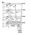
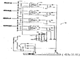
제5f도에 도시한 바와 같이,2차 과전류 트립 회로(72)는트립 실리콘 제어 정류기(SCR)(11)가 도전되게 하는 프로그램 가능한 단일 접합 트랜지스터 (108)(제5c도에 도시)를 제공하고, 재폐쇄기를 개방하는 트립 코일에 전압을 가하는 4개의 동일 작동 증촉기 회로(106)로 구성 되어 있다. SCR(110)에 대한 공급전류는 트립 작동 발생시에 회로를 개방시키는 재폐쇄기 내부 접속에 의하여 차단된다. 그들 각각에 대한 인버어팅 입력은 가변 분압기 (120)에 의하여 결정된 전압이다. 분압기(120)는 18볼트가 공급되고, 병렬 저항 (140)을 삽입하도록 딥(dip)스위치 (130)상에 적당한 연결부를 폐쇄하므로 가변된다. 작동 증폭기(150)에 대한 비반적 입력 전압의 값이 부입력 이상으로 상승될때, 캐패시터(160)를 도전 및 충전이 시작된다.As shown in FIG. 5F, the secondary
작동 증폭기(150)의 정입력으로 인가된 충분한 교류 입력 신호가 비반전 입력 이상일 경우, 증폭기(150)는 프로그램 가능한 단일 접합 트랜지스터(108)를 SCR(110)이 도전되게 하므로 작동시킬 수 있다. RC 회로망은 우너래의시간 특성을 제공한다.SOCT(72)내의 작동 증폭기의 출력은 컴퓨터 명령 (CA2)상에서 접지로 크램프될 수 있다.If the sufficient AC input signal applied to the positive input of the
이러한 일은 마이크로프로세서가 효과적으로 작동될때 발생한다.This happens when the microprocessor runs effectively.
프로그램 가능한 단일 접합 트랜지스터(180)는 스위치 되지 않은 전압(통상 24볼트)이 달링톤 트랜지스터어레이(182)와 제 5 c도에 도시된 그에 연결 회로에 의하여 18볼트 이하로 떨어질때 작동되지 못하게도 한다. 이는 바테리 레벨이 매우 낮아 트립 작동되지 않을때 트립 작동을 못하도록 작동된다.Programmable single junction transistor 180 prevents the unswitched voltage (typically 24 volts) from operating when it falls below 18 volts by Darlington transistor array 182 and its connecting circuit shown in FIG. . It is activated to prevent tripping when the battery level is very low and tripping is not active.
재폐쇄기 제어장치(10)에 여분 검사기(redundancy cheecker)(190)는 재폐쇄기의 불리한 환경에 필수적이며, 소프트웨어 및 하드웨어에서의 여러가지 레벨로 작동한다. 예를들면, 제 5 g도의 여분 검사기(190)는 폐쇄 코일을 제어하는 전력 전계효과 트랜지스터(FET)와 트립 코일을 제어하는 SCR(110)에 작동 신호가 인가되도록 구성되어 있다. 트립 SCR(110)을 게이트 하는 트랜지스터(186)는 마이크로 프로세서로부터 P4및 P5와, 부정 P6(P4, P5, P6)의 적에 대한 부정(negation)이 만족되지 않는한 도통되지 않는다. 마찬가지로, 폐쇄코일을 제어하는 전력 FET(184)를 동작시키는 트랜지스터(188)는 부정 P4와 P5 및 P6(P4, P5, P6)의 상태가 만족될때까지 도통하지 못한다.A redundancy cheecker 190 in the
또한 개인 기판은 마이크로컴퓨터 회로를 비교적 고전압선으로부터 떨어지게하는 광학 분리 회로로 구성되어 있다. 제 5 h 도는 이들 원격 명령을 모니터하는 광학 분리 회로와, 채폐쇄기 제어장치의 주 기능을 나타내고 있다. 이 분리 회로는 모니터 하는 원격 폐쇄(360), 원격 트립(362), 최소 트립 멀티플렉서(364)와 액세사리(366)계전기로 구성되어 있는데, 제 5 c도에도 도시되어 있다. 또한, 트립 코일(368) 및 폐쇄코일(370)도 모니터하며, 그들의 SCR(11)과 FET(184)는 분리기(372 및 374)에서 제어한다.The individual substrate also consists of an optical isolation circuit that separates the microcomputer circuit from relatively high voltage lines. FIG. 5h shows the main functions of the optical separation circuit for monitoring these remote commands and the shredder control device. This disconnect circuit consists of a remote closure 360 that is monitored, a remote trip 362, a minimum trip multiplexer 364 and an accessory 366 relay, which is also shown in FIG. The trip coil 368 and the closing coil 370 are also monitored, and their SCRs 11 and FETs 184 are controlled by separators 372 and 374.
또한, 재폐쇄기 제어 장치내에는 전력 공급 제어장치(82)(제 6 도에 도시), 직류-직류 변활기(80)와 재폐쇄기 인터페이스 기판이 그 내부에 장착된다. 상기 주요부품과, 24볼트 바테리(78), 트립 캐패시터(76), 전력 공급 제어장치(82)로 24볼트를 공급하는 110볼트 변압기(74) 및 재폐쇄기 제어 장치의 프론트 패널상에 장착된 피스톨 그립 스위치(30)는 제 6 도에 도시된 재폐쇄기 제어장치(10)의 선간 선도로 도시되어 있다. 일반적으로, 제 3도의 블록선도로 나타낸 인터페이스 모듈(70)은 비교적 높은 전력 또는 재폐쇄기 및 계전기의 전압 성분과 제어장치의 사용자에 의하여 조성되는 전위 입력을 처리한다.In the recloser control device, a power supply control device 82 (shown in FIG. 6), a DC-
다른 대부분의 마이크로컴퓨터 설계 분야는 물론, 소프트웨어이다. 두가지 유형의 소프트웨어는 작동 장치와 응용 프로그램으로 이용된다. 실시간 작동 장치인 MERTOS는 마이크로컴퓨터를 기초로한 제어 장치내에서, 이들 작동이 처리도도록 특별히 설계된다. MERTOS는 소프트설계에 대한 모듈방식의 소프트웨어 기초를 두고 있다. MERTOS는 여러가지 독립 타스크를 제어 장치에 공통적인 것이다.Most other areas of microcomputer design are, of course, software. Both types of software are used as operating devices and applications. MERTOS, a real-time operating device, is specifically designed to handle these operations within microcomputer-based control devices. MERTOS has a modular software foundation for soft design. MERTOS is common to control devices with a number of independent tasks.
마이크로컴퓨터내의 상주(resident)는 마이크로 컴퓨터내에 여러가지 서브프로그램의 실행을 감시하는 기능을 한는 실행 프로그램이다. 이들 실행 프로그램은 실시간에 연산 및 입력/출력의 실행을 하도록 몇개의 서브 프로그램 가운데 마이크로컴퓨터 지원을 할당한다.A resident in a microcomputer is an executable program that functions to monitor the execution of various subprograms in the microcomputer. These executable programs allocate microcomputer support among several subprograms to perform computations and input / output execution in real time.
컴퓨터 기능의 실행 프로그램 방법은 제 3 도의 흐름도에 도시되어 있으며, 블록들은 실행 프로그램에 의하여 요구되는 주요기능 성분 및 다른 서브프로그램/타스크를 나타낸다. 전력을 인가하거나, 재시작에 따라, 컴퓨터는 판독/기록 메모리의 초기와, 전기장치 또는 제어장치에 맞는 매개변수 결정, 데이타 카운터와 레지스터(제13도참조)의 여러 레지스터의 초기화를 부트스트랩핑 작동에 의하여 지시받는다. 컴퓨터가 작동상태로 부트스트랩 되는 경우, 인터럽트는 인터럽트 조정기에 의하여 명령되는 대로 발생되도록 이루어진다. 인터럽트는 중앙 처리 장치(CPU)가 각각 명령 사이클의 일부로써 시험하도록 연속적인 입력으로서 존재한다.The execution program method of the computer function is shown in the flowchart of FIG. 3, and the blocks represent the main functional components and other subprograms / tasks required by the execution program. Upon powering up or restarting, the computer bootstraps the initial read / write memory, determines the parameters for the electrical or control device, initializes the data counters and registers of the registers (see Figure 13). Are instructed by When the computer bootstraps into an active state, an interrupt is made to occur as instructed by the interrupt handler. The interrupt is present as a continuous input for the CPU to test as part of each instruction cycle.
인터럽트 조정기 흐름도(200)는 제 7 도에 도시되어 있다. 제 4d도에 도시된 아날로그-디지탈 변환기(68)에 기억된 데이타는 판독 데이타 블록(210)에서 1차 판독되고, 그다음 아날로그-디지탈 변환기(68)의 테이타 블록(220)에서 트리거되어, 샘플 홀드 회로(60)에 데이타 기억을 획득한다. 그다음, 제 4 d도에 표시한 아날로그 멀티플렉서(62)는 블록(230)내에서 선택되어 다음 아날로그 신호를 전송하기 위해 명령을 받는다. 블록(240)에서는 프로그램이 분리된다. 접지 채널이 작동되지 않는 경우, 디지탈-아날로그 변환기(250)는 블록(260)에서 위상 데이타를 선택한다. 접지 채널이 작동되는 경우, 블록(270)에서 접지 데이타로 설정된다. 그 다음 결합 갱신 블록(280)에서 작동한다. 그후 프로그램 가능한 타이머는 타이머 갱신 블록(290)에서 갱신된다. 이들 갱신 타스크가 수행된후, 프로그램은 인터럽트 블록(300)에서 더 많은 인터럽트를 허용하는 상태로 설정되고, 프로그램의 시작으로 복귀한다. 전력이 재폐쇄기 제어 장치(10)에 인가되고, 마이크로프로세서(38)가 감시 타이머(50), 인터럽트 조정기 루틴(200)에 의한 결정에 따라 정상적으로 작동될때의 정상 상태하에서는 모든 프로그램의 최상위 순위를 갖는다. 감시 타이머(50)가 에러를 검출하는 경우, 제13도에 도시된 바와같이 재시작이 시작된다. 물론, 바테리(78)가 마이크로프로세서(38)의 정상 작동을 하게 하느데 불충분할때, SOCT(72)는 모든 프로그램을 무시한다. 인터럽트 조정기 모듈(200)은 마이크로프로세서(38)가 디지탈화된 입력 데이타를 획득하는 장치이다.Interrupt regulator flowchart 200 is shown in FIG. The data stored in the analog-to-
제 2 도에서는 샘플되도록 기본적인 네개의 신호가 되시되어 있으며, 각 입력 신호가 전력 사이클동안 5번 샘플되는 경우, 그의 RMS제곱치에 비례한 매우 정확한 근사치는 샘플값은 제곱하고, 가장 최근의 5제곱 샘플을 가산시키므로 계산된다. 그러므로, 샘플 간격은 0.833밀리초이며, 마이크로프로세서 제어되는 프로그램 가능한 타이며(42)에 의하여 결정된다. 인터럽트 조정기 모듈(200)의 프로그램이 실행되는 각각의 시간은, 제 5 aa도에 도시된 디지탈-아날로그 변환기(250)가 인터럽트 조정기 모듈(200)의 프로그램의 블록(260 및 270)에서 적당히 셋트된다. 디지탈-아날로그 변환기(250)는 제 2 도에 도시된 정규화 스케일링 증폭기(310)의 일부이다. 정규화 스케일링 증폭기(310)의 잔유 부분은 제 5 aa도에 도시된 연산 증폭기(312)이다. 디지탈-아날로그 변환기(25)는 접지 및 위상 트립 레벨에 대해 디탈화된 데이타를 임의 입력 데이타로 정규화 하기 위해 블럭(260 및 270)에서 인터럽트 조정기 루틴의 마이크로프로세서에 의해 발생된 신호에 응답하여 연산 증폭기(312)의 이득을 변화시킨다. 다양하게 미리 선정된 정규화 기준에 대한 입력 데이타의 정규화는 입력 데이타의 넓은 범위를 포괄시키도록 하는데 필요하다. 제 2 도에 도시된 정규화 스케일링 증폭기(310)는 제 5 aa도에 있는 한 블럭으로 결합되는 유일한 증폭기이다.In Figure 2, the basic four signals are sampled, and if each input signal is sampled five times during a power cycle, a very accurate approximation proportional to its RMS squared is squared with the sampled value and the most recent five squared It is calculated by adding a sample. Therefore, the sample interval is 0.833 milliseconds, which is determined by the microprocessor controlled
상기 인터럽트는 CPU가 검사 상태 비트(폴링 : polling)에 의한 소프트웨어 레벨로 보다 적은 하드웨어 레벨로 재작동하도록 하게 한다. 통상적인 프로그램 입출력보다 하드웨어를 더욱 필요로 하지만 인터럽트는 비교적 빠르고 직접적인 응답을 한다. MERTOS작동 시스템에 있어서 인터럽트 조정기 모듈(200)은 우선 순위 인터럽트 시스템에 따라 중요하고 중요치 않은 인터럽트 사이를 구별할 수 있도록 설치된다. 우선 순위 인터럽트에 따라, CPU는 인터럽트의 우선 순위가 현재 실질적인 작동에서보다 더욱 우수하지 않는한 인터럽트 되지 않는다.The interrupt causes the CPU to be reactivated at less hardware level with the software level by the check status bit (polling). It requires more hardware than normal program I / O, but interrupts are relatively quick and direct. In the MERTOS operating system, the interrupt handler module 200 is installed to distinguish between critical and noncritical interrupts according to the priority interrupt system. In accordance with priority interruption, the CPU is not interrupted unless the priority of the interrupt is better than in current practical operation.
인터럽트가 클리어 된 후에 작동 시스템은 우선 순위 시스템에 따른 서브프로그램의 실행을 감시한다. 각 서브프로그램은 그들을 보조하는 다른 서브프로그램의 키보즈 같은 주변 장치에 의한 단속에 대한 중요성을 나타내는 우선 순위와 연관되어 있다.After the interrupt is cleared, the operating system monitors the execution of the subprogram according to the priority system. Each subprogram is associated with a priority that indicates its importance for enforcement by peripherals such as keyboards of other subprograms that assist them.
제13도를 참고하면, 실행된 제 1 프로그램은 포어 그라운드(FOREGROUND)서브프로그램이다. 이는 실행된 최고 우선 순위 시간-관계 타스크를 나타내는데, 다른 것이 아닌 인터럽트신호에 의해 실행된다. 미들그라운드(MIDDLEGROUND)는 서브프로그램엔 포러그라운드보다 저 우선 순위의 서브프로그램을 나타낸다. 최저 우선 순위 프로그램은 백그라운드(BACKGROUND)서브프로그램이다. CPU의 작동을 지시하는 작동 시스템은 이들 서브프로그램의 상태를 개별적으로 시험하고 서브프로그램이 인터럽트 되면, CPU는 인터럽트 발생할때에 본래의 상태로 재저장된다. 서브 프로그램이 인터럽트되지 않고 완료된 경우, CPU는 다음의 최저 레벨 서브프로그램을 진행시킨다. 따라서 각 서브 프로그램은 다음 서브프로그램이 시작되기 전에 우선 순위구조에 따라 완료된다.Referring to FIG. 13, the executed first program is a foreground sub-program. This represents the highest priority time-related task executed, which is executed by an interrupt signal that is not otherwise. The middle ground (MIDDLEGROUND) indicates a subprogram having a lower priority than the foreground in the subprogram. The lowest priority program is the BACKGROUND subprogram. The operating system instructing the operation of the CPU individually tests the state of these subprograms and when the subprogram is interrupted, the CPU is restored to its original state when the interruption occurs. If the subprogram completes without interruption, the CPU proceeds to the next lowest level subprogram. Therefore, each subprogram is completed according to the priority structure before the next subprogram is started.
예를들면, FOREGROUND동안, 다음 타스크는 포어 그라운드 프로그램(400)을 위한 흐름도로 제 8 도 내지 제10도에 도시된 바와같이 실행된다. 포어그라운드 플래그 상태(flag condition)는 플래스 판단 블록(402)내에서 실행된다. 포어그라운드 플래그가 셋트된 경우, 프로그램은 시작 단계로 복귀한다. 포어그라운드 플래그가 셋트되지 않은 경우, 이들 플래그 블록(404)내에서 셋트된다. 블록(406)에서는 데이타 처리가 실행되며, 프로그램이 이 단계에 있는 동안 제곱 알고리즘은 입력 신호의 RMS값에 대한 비례값을 발생시키도록 실행된다. 이러한 처리가 실행된 후에는 데이타가 접지 결정 블록(408)에서 접지 데이타인가를 판단한다. 만일 그렇지 않은 경우에는 위상 데이타일 것이다. 위상 데이타인 경우, 순간적인 트립 작동이 바람직한 것인지의 결정은 순간 트립판단 블록(410)에서 결정된다. 순간 트립 작동이 바람직한 경우, 이 데이타는 순간 트립 레벨을 초과하지 않았는지를 결정하는 순간 크기 판단 블록(412)내에서 시험된다. 순간 트립 레벨이 초과된 경우, 순간 트립 플래그는 순간 플래그 블록(414)에서 셋트되고, 프로그램은 인터럽트로부터 복귀한다. 순간 크기 판단 블록(412)내에서 데이타가 순간 트립 레벨을 초과하지 않는 경우, 데이타가 최소 트립 판단블럭(416)에서 시험되면 최소 트립 레벨을 초과하였는지의 여부를 판단한다. 순간 트립 작동이 순간 트립 판단 블록(410)내에서 결정되는 바와같이 바람직하지 못할 경우 데이타는 최소 트립 레벨을 초과하거나, 초과하지 않았는지의 여부를 결정하기 위해 최소 트립 판단 블록(416)으로 바로 진행된다. 데이타가 최소 트립 판단 블록(416)에서 최소 트립 레벨을 초과하지 않았을 경우, 최소 트립 플래그는 최소 트립 플래그 블록(418)내에서 리셋트되며, 프로그햄은 인터럽트로부터 복귀한다. 데이타가 최소 트립 레벨을 초과한 경우, 이는 모조 지점(dummy piont )(A)을 통과한다.For example, during FOREGROUND, the following task is performed as shown in FIGS. 8-10 with a flow chart for the foreground program 400. A foreground flag condition is executed in the flag decision block 402. If the foreground flag is set, the program returns to the start stage. If the foreground flag is not set, it is set in these flag block 404. At block 406, data processing is performed, while the square algorithm is executed to generate a value proportional to the RMS value of the input signal while the program is at this stage. After this processing is performed, it is determined at ground decision block 408 whether the data is ground data. Otherwise it will be phase data. In the case of phase data, a determination of whether an instant trip operation is desired is determined in an instant trip decision block 410. If instantaneous trip operation is desired, this data is tested in instantaneous size determination block 412 to determine whether the instantaneous trip level has been exceeded. If the instantaneous trip level is exceeded, the instantaneous trip flag is set in the instantaneous flag block 414 and the program returns from the interrupt. If the data in the instantaneous size determination block 412 does not exceed the instantaneous trip level, it is determined whether the data has exceeded the minimum trip level when tested in the minimum trip decision block 416. If the instant trip operation is undesirable as determined in the instant trip decision block 410, the data proceeds directly to the minimum trip decision block 416 to determine whether or not the minimum trip level has been exceeded or not exceeded. do. If the data did not exceed the minimum trip level in the minimum trip determination block 416, the minimum trip flag is reset in the minimum trip flag block 418, and the program returns from the interrupt. If the data exceeds the minimum trip level, it passes through a dummy pion A.
데이타가 접지 데이타인가를 결정하는 접지 결정 판단 블록(418)으로 돌아와서, 만일 접지 데이타인 경우, 접지 트립 블록이 작동되어지는가를 결정하는 접지 동작 결정 판단 블록(420)으로 진행된다. 접지 트립 블록이 작동되는 경우, 프로그램은 인터럽트로부터 복귀한다. 접지 동작 결정 판단 블록(420)으로부터 모조 지점(B)까지의 접지 데이타는 이미 설명된 위상 데이타의 처리 과정에 유사하게 실행된다. 위상 데이타가 최소 트립 레벨을 초과하는 가의 결정에 따라, 모조 지점(A)으로부터 위상 데이타로 복귀되는 경우, 최소 트립 플래스는 최소 플래그 블록(422)내에 셋트된다. 그다음, 위상 제 1 시간 전류 플래그를 제1 TCC판단 블록(424)내에서 판단된다. 제1 TCC플래그가 셋트되는 경우, 제 1 위상 TCC어드레스는 제1 TCC 어드레스 블록(426)내에서 인출명령으로 프로그램을 엔터(enter)한다. 제1 TCC플래그가 제1 TCC플래그 판단블록(424)에서 셋트되지 않는 경우, 제 2 위상 TCC플래그를 위한 어드레스는 인출 명령의 실패에 의해 제 2 TCC 어드레스 블록(428)에서 프로그램을 엔터한다. 그다음, 적당한 TCC어드레스 기억 블록(430)내에 기억된다. 마찬가지로, 접지 위상 데이타는 모조 지점(B)과 어드레스 기억 블록(430)사이에서 유사하게 처리된다. 이 지점에서 데이타는 시험하고자 하는 입력 위상의 RMS의 비례값을 나타내는 비교적 큰 수이다. 이 RMS의 해당값이 시간-전류 특성의 계산을 필요한 것은 아니다. 그러므로, 이 데이타는 데이타 압축 블록(commpression block)(432)내에 상당한 범위 가운데 하나를 선택하므로 압축된다. 그 다음, 압축 데이타는 TCC계산 블록(434)에서 시간-전류 특성(TCC)계산을 실행하도록 하는데 새용된다.Returning to ground decision determination block 418, which determines whether the data is ground data, and if so, proceeds to ground operation decision determination block 420, which determines if the ground trip block is actuated. When the ground trip block is activated, the program returns from the interrupt. The ground data from the ground operation decision determination block 420 to the dummy point B is similarly executed in the processing of the phase data already described. In accordance with the determination of whether the phase data exceeds the minimum trip level, when returning from the dummy point A to the phase data, the minimum trip flag is set in the minimum flag block 422. Then, the phase first time current flag is determined in the first
이러한 단계후에, 프로그램은 모조 지점(C)으로 진행된다. 이후, 트립 레벨 판단 블록(436)내에서 트립 레벨이 도착하였는지를 결정한다. 트립 레벨이 도착되지 못한 경우, 상기 포어그라운드 프로그램(400)은 인터럽트로부터 복귀된다. 트립 레벨이 도착된 경우, 프로그램은 내부 트립 플래그 블록(438)에서 내부 트립 플래그를 셋트되도록 진행되나. 트립의 소스는 트립 소스 블록(440)에서 결정되고, 포어그라운드 프로그램(400)은 인터럽트로부터 복귀된다.After this step, the program proceeds to the dummy point (C). Then, it is determined in the trip level decision block 436 whether the trip level has arrived. If the trip level does not arrive, the foreground program 400 returns from the interrupt. If the trip level has arrived, the program proceeds to set the internal trip flag in the internal trip flag block 438. The source of the trip is determined at the trip source block 440, and the foreground program 400 returns from the interrupt.
마이크로프로세서(38)가 트립을 발생시키거나, 어떠한 유형의 플래그를 폐쇄할때, 제11도의 흐름도에 도시된 트립 폐쇄 프로그램(500)이 실행된다. 먼저, 록(lock)플래그가 록 플래그 판단 블록(502)내에서 셋트되었는지의 여부를 판단한다. 록 플래그가 셋트된 경우, 트립-폐쇄 프로그램(500)은 서브루틴으로부터 복귀된다. 록 플래그가 셋트되지 않은 경우, 데이타는 내부 트립의 존재 여부를 알기 위하여 내부 트립 판단 블록(504)에서 판단한다. 내부 트립이 존재하는 경우, 트립 판단 블록(506)에서 재폐쇄기의 상태를 판단한다. 재폐쇄기가 트립되지 않은 경우 발생 트립 블록(508)에서 트립 신호를 발생된 다음 트립된 플래그 셋트 블록(510)에서 트릅된 플래그를 셋트한다. 이후, 트립-오프 판단 블록(512)에서 트립이 금지되었지를 결정한다. 트립 판단 블록(506)을 다시 설명하면, 재폐쇄기가 이미 트립된 경우에는 프로그램이 즉시 트립-오프 판단 블록(512)으로 진행된다. 내부 트립 판단 블록(504)을 다시 설명하면, 트립 또는 폐쇄 신호 소스가 내부 트립이 아닌 경우, 외부 트립 판단블록(514)에서 외부 트립 존재하는가를 결정한다. 만일 외부 트립이 존재하는 경우, 프로그램은 트립 판단 블록(506)으로 입력되어 내부 트립에 존재할 경우처럼 진행된다. 외부 트립 판단 블록(514)에서 외부 트립이 존재하지 않는 경우, 프로그램은 트립-오프판단 블록(512)으로 진행된다. 트립-오프 판단 블록(512)에서는 이 프로그램은 트립 오프 플래그가 셋트되었는가를 판단한다.When the
만일, 셋트된 경우에는 트립 턴-오프 블럭(516)에서 트립 신호를 턴-오프한다. 그 다음, 트립 오프 플래그는 리셋트 트립 블록(518)에서 트립 오프 플래그를 리셋트한다. 이에따라, 트립 플래그는 리셋트 트립-오프 블록(518)에서 리셋트된다. 이후, 내부 트립 온 판단 블록(522)에서는, 내부 트립이 온 상태인지 여부를 결정한다. 내부 트립이 온인경우, 내부 트립 플래그는 리셋트 내부 트립 플래그 블록(524)내에 리셋트된다. 상기 내용에 따라서, 플래그는 폐쇄-온(close-on)판단 블록(526)내에서 폐쇄 상태로 있는지의 여부를 결정하기 위해 판단한다. 내부 트립은 판단 블록(522)에서 내부 트립-온 상태가 내부 트립내에 존재하지 않는다면, 프로그램은 폐쇄-온 판단 블록(526)으로 즉시 진행된다. 트립-오프 상태가 트립-오프 결정 블록(522)에 존재하지 않은 경우, 프로그램은 즉시 폐쇄-온 판단 블록(522)으로 진행된다. 폐쇄-온 상태가 폐쇄-온 판단 블록(526)에 존재하는 경우, 재폐쇄기의 상태는 폐쇄 판단 블록(528)에서 다시 판단한다. 여기서 프로그램은 트립 판단 블록(506)과 트립-오프 판단 블록(512)간에 이어지는 프로그램과 유사한 과정으로 진행된다. 그러나, 이러한 브랜치 완결시에, 트립 폐쇄루틴(500)은 서부루틴으로부터 복귀한다. 폐쇄-온 상태가 폐쇄-온 판단 블록(526)에 존재하지 않는 경우, 프로그램은 폐쇄-오프 판단 블록(530)에서 폐쇄-오프 상태의 존재여부를 결정하도록 진행된다. 폐쇄-오프 상태가 존재하는 경우, 폐쇄신호는 폐쇄신호 턴-오프 블록(532)에서 턴-오프된다.If set, the trip signal is turned off at the trip turn-off block 516. The trip off flag then resets the trip off flag at reset trip block 518. Accordingly, the trip flag is reset at reset trip-off block 518. The internal trip on decision block 522 then determines whether the internal trip is on. If the internal trip is on, the internal trip flag is reset in the reset internal trip flag block 524. In accordance with the above, the flag is determined to determine whether it is in a closed state within a close-on decision block 526. If the internal trip does not exist in the internal trip at decision block 522, the program proceeds immediately to the closed-on decision block 526. If no trip-off condition exists in the trip-off decision block 522, the program immediately proceeds to the close-on decision block 522. If the closed-on state is present in the closed-on decision block 526, the state of the recloser is determined again in the closed decision block 528. Here, the program proceeds to a process similar to the program following between the trip determination block 506 and the trip-off determination block 512. However, upon completion of this branch, the trip closure routine 500 returns from the western routine. If the closed-on state is not present in the closed-on decision block 526, the program proceeds to determine whether the closed-off state exists in the closed-off decision block 530. If there is a closed-off state, the closed signal is turned off in the closed signal turn-off block 532.
상기 내용에 따라서, 폐쇄 플래그는 폐쇄된 플래그 블록(534)에서 리셋트된다. 폐쇄-오프 플래그가 폐쇄-오프 플래그 블록(536)에서 리셋트된 다음 트립-폐쇄 프로그램(500)은 서브루틴으로부터 복귀된다. 폐쇄-오프 상태가 폐쇄-오프 판단 블록(530)에서 존재하지 않는 경우, 트립-폐쇄 루틴(500)은 서브루틴으로부터 복귀된다.In accordance with the above, the closed flag is reset in the closed flag block 534. The close-off flag is reset at the close-off flag block 536 and then the trip-close program 500 returns from the subroutine. If no close-off condition exists in the close-off decision block 530, the trip-close routine 500 returns from the subroutine.
미들그라운드는 데이타를 조작하고, 디지탈 표시장치를 갱신하며, 키보드 작동을 할때처럼 상기 루틴실행이 이루어진다. 제14a도는 제13도의 프로그램이 연속으로 이어지는 미들그라운드 루틴(600)의 흐름도이다. 미들그라운드의 프로그램은 처음 반복 타스크 블록(602)에서 반복 타스크를 실행한다. 이들 타스크는 모두 동일한 우선 순위이며, 미들그라운드 루틴(600)이 시작하는 경우 연속적으로 실행된다. 연속 명령은 그렇게 중요치 않으며, 연속 명령에 의한 반복 타스크는 다음을 포하하고 있다.The middle ground operates the routine as if manipulating data, updating the digital display, and operating the keyboard. FIG. 14A is a flowchart of a middle ground routine 600 in which the program of FIG. 13 is continuously connected. The program in the middle executes the repetitive task in the first repetitive task block 602. These tasks are all of the same priority and are executed continuously when the middle routine 600 starts. Continuation instructions are not so important, and repetitive tasks by continuation instructions include:

반복 타스크 블록(602)에서 모든 반복 타스크의 완료후에, 미들그라운드 프로그램(600)은 장, 단기 큐 타스크 플래그가 셋트되는 타스크 큐 블록(604)으로 입력된다. 또한, 이 작용은 제14b도, 제14c도 및 제14d도에 상세리 도시되어 있다. 장 단기 큐 상의 분기점은 약 5분이다. 타스크가 5분 또는 그 이하의 시간내에 작동되는 경우에는 단기 큐로 입력된다. 타스크가 5분이상의 시간에 작동되는 경우에는 장기 큐에 입력된다. 장기 큐가 타스크 입력후에 실행되도록 타스크를 수용할 수 있게 계획된다. 미들그라운드 프로그램(600)이 타스크 큐 블록(604)을 통과한 후에, 플래그 타스크 판단 블록(606)에서 플래그된 타스크가 존재하지는지의 여부를 결정한다. 존재하지 않는 경우, 프로그램은 제13도에 도시된 인터럽트 지점(608)으로부터 복귀된다. 플래그된 타스크 판단 블록(606)에 존재하는 경우 이들은 실행 플래그 타스크 블록(610)에서 실행된다는 것을 알수 있다. 제14d도에는 일반화된 실행 플래그 타스크가 도시되어 있다.After completion of all repetitive tasks in repetitive task block 602, the middle program 600 is input to the task queue block 604 in which the long and short queue task flags are set. This action is also shown in detail in FIGS. 14B, 14C and 14D. The branch point on the short-term queue is about 5 minutes. If the task runs within five minutes or less, it is entered as a short queue. If the task is run for more than 5 minutes, it is entered in a long queue. The long-term queue is planned to accommodate the task so that it runs after the task is entered. After the middle program 600 passes through the task queue block 604, it is determined whether or not the task flagged in the flag task decision block 606 exists. If not present, the program returns from the interrupt point 608 shown in FIG. If present in flagged task determination block 606, it can be seen that they are executed in execution flag task block 610. A generalized execution flag task is shown in FIG. 14d.
제14b도는 제14a도에 도시된 타스크 큐 블록(604)의 확대도이다. 먼저 스케일 클럭 틱(tict)판단 블록(612)에서 스케일 클럭 틱인가를 결정한다. 스케일 클럭 틱이 존재한다면, 프로그램은 즉시 종료로 스킵되면서 플래그된 타스크 판단 블록(606)으로 입력된다. 스케일 클럭 틱이 존재하지 않는다면, 실시간 클럭을 실시간 갱신 블록(614)에서 갱신한다. 그다음은 단기 큐 블록(615)에서 타스크가 실행되기에 적당한가 단기 큐를 검사한다. 상기 내용에 따라서, 장기 큐 블록(616)에서 유사한 방식으로 장기 큐를 검사하고, 프로그램은 플래그된 타스크 판단블록(606)으로 입력된다.FIG. 14B is an enlarged view of the task queue block 604 shown in FIG. 14A. First, at scale clock tick determination block 612, it is determined whether to scale clock ticks. If there is a scale clock tick, the program is skipped to end immediately and entered into the flagged task decision block 606. If there is no scale clock tick, then the real time clock is updated at real time update block 614. Next, in the short queue block 615, the task checks whether the task is suitable for execution. In accordance with the above, the long term queue is examined in a similar manner in the long term queue block 616, and the program is input to the flagged task decision block 606.
제14c도는 제14b도에 포함된 단기 큐 블록(615)의 확대도이다. 도시안된 어떤 유사한 프로그램이 장기 큐에 대해 존재한다. 이들 프로그램중 하나의 각각의 플래그 타스크에 대해 존재한다. 제14c도에 확대 도시된 단기 큐 블록(615)에 있어서, 먼저 타스크 타이머 플래그가 0인지 아닌지를 블록(618)에서 결정한다. 플래그가 0인 경우 프로그램은 연속 지점으로 입력되므로 몇몇의 다른 타스크로 스킵된다. 연속 지점은 각 플래그 타스크에 대해 존재하는데, 이는 본질적으로 각 플래그 타스크 프로그램의 시작으로 입력된다. 일반화된 플래그 타스크 프로그램은 제14d도에 도시되어 있다. 모든 플래그 타스크는 제14a도의 실행 플래그 타스크 블록(610)내에 포함된다. 만일, 타스크 타이머 플래그가 0이 아닐 경우, 단기 큐 프로그램(615)은 타이머-1 블록(620)에서 타이머로부터 1을 감산에 의해 계속된다. 그다음, 타이머=0블록(622)에서 타이머가 0과 일치하는지를 검사한다. 만일 타이머가 0인 경우에는 타스크-1 블록(624)에서 타스크 상태로부터 1을 감상한다. 그 다음 TTF+1 블록(626)에서 타스크 타이머 플래그에 1을 증가시키고, 단기 큐는 단기 큐 블록(615)에 포함된 다른 플래그 타스크를 실행하기 위해 계속 진행된다.FIG. 14C is an enlarged view of the short-term queue block 615 included in FIG. 14B. Some similar program, not shown, exists for long term queues. There is a flag task for each of these programs. In the short-term queue block 615 enlarged in FIG. 14C, first, in block 618, it is determined whether the task timer flag is zero or not. If the flag is 0, the program is entered as a continuous point and is skipped to several other tasks. A continuation point exists for each flag task, which is essentially entered at the beginning of each flag task program. The generalized flag task program is shown in FIG. 14d. All flag tasks are included in the execution flag task block 610 of FIG. 14A. If the task timer flag is not zero, the short-term queue program 615 continues by subtracting 1 from the timer at timer-1 block 620. Next, at timer = 0 block 622, check if the timer matches zero. If the timer is zero, task-1 block 624 listens to 1 from the task state. Then, in TTF + 1 block 626, the task timer flag is incremented by one, and the short-term queue continues to execute other flag tasks included in the short-term queue block 615.
타스크 큐 서브프로그램이 완료된 후 플래그 타스크는 실행되면서, 플래그 타스크 블록(610)에서 플래그 타스크를 실행한다. 플래그 타스크 판단 블록(606)이 시험되는 타스크 상태 신호는 그들이 마스크되지 않는한, 플래그 타스크를 확실히 실행시키도록 하며, 타이머=0판단 블록(622)에서 시험된 타스크 타이머는 타스크의 시간 우선 순위 할당 제어하도록 제공한다.After the task queue subprogram is completed, the flag task is executed, and the flag task block 610 executes the flag task. The task status signal for which the flag task determination block 606 is tested ensures to execute the flag task unless they are masked, and the task timer tested in the timer = 0 decision block 622 controls the time priority assignment of the task. To provide.
일반화된 타스크 실행 프로그램은 제14d도에 도시되어 있다. 먼저, 타스크 플래그=0 판단 블록(628)에서 타스크 플래그가 0인지 아닌지를 판단한다. 타스크 플래그가 0이며, 프로그램은 부가적인 타스크로 계속 진행된다. 타스크 플래그가 0이 아니면, 타스크 마스크는 타스크 마스크=0 판단 블록(630)에서 타스크 마스크가 0인지 아닌지를 판단한다. 타스크 마스크가 0일때에는 마스크-1 블록(623)에서 마스크로부터 1을 감산한다. 이러한 단계후, 명세 타스크 프로그램이 타스크블록(634)에서 실행된다. 이러한 타스크의 실행에 따라, 플래그+1 블록(636)에서 플래그에 1을 가산하고, 마스크+1 블록(638)에서 마스크에 1을 가산한다. 이다음, 프로그램 재입력이 제14d도와 제13도에 도시된 인터럽트 지점(608)으로부터 복귀된다. 타스크 상태=0 판단 블록(630)을 다시 설명하며, 타스크 마스크가 0이 아닐 경우에는 프로그램이 분기되고, 타스크 상태=0 판단 블록에서 타스크가 0인지를 판단한다. 만일, 타스크가 0인 경우에는 제14c도와 함께 도시된 타스크 시간 =0 판단 블록(622)에서 타스크 타이머가 0인가를 판단한다. 타스크 타이머가 0이 아닌 경우에는 프로그램은 부가적인 타스크 루틴을 수행하는 계속 지점으로 진행된다. 타스크 타이머가 0인 경우에는 제14d도 및 제13도에 도시된 인터럽트 지점(608)으로부터 프로그램이 계속된다. 타스크 상태=0판단 블록(640)을 다시 설명하며, 타스크 상태가 0이 아닌 경우에는 상태+1블록(641)에서 상태 1을 가산한다. 이다음, 근원 스택 이동 블록(644)에서 중단점 어드레스를 스택으로 이동한다. 상기 프로그램이 실행되면 프로그램은 타스크 복귀 블록(646)에서 인터럽트된 타스크를 실행하는 곳으로 복귀한다.The generalized task execution program is shown in FIG. 14d. First, in the task flag = 0 decision block 628, it is determined whether the task flag is 0 or not. The task flag is zero, and the program continues with additional tasks. If the task flag is not zero, the task mask determines whether the task mask is zero or not at task mask = 0 determination block 630. When the task mask is 0, 1 is subtracted from the mask in the mask-1 block 623. After this step, the specification task program is executed in task block 634. In accordance with the execution of this task, 1 is added to the flag at flag + 1 block 636 and 1 is added to the mask at mask + 1 block 638. Then, program re-entry is returned from the interruption point 608 shown in FIGS. 14D and 13. The task state = 0 determination block 630 will be described again. When the task mask is not 0, the program branches, and it is determined whether the task is 0 in the task state = 0 determination block. If the task is 0, it is determined whether the task timer is 0 in the task time = 0 determination block 622 shown in FIG. 14C. If the task timer is non-zero, the program proceeds to the point of continuing to perform additional task routines. If the task timer is zero, the program continues from the interrupt point 608 shown in FIGS. 14D and 13. The task state = 0 determination block 640 will be described again. If the task state is not 0, the state 1 is added to the state + 1 block 641. The breakpoint address is then moved to the stack in the source stack move block 644. When the program is executed, the program returns to where to execute the interrupted task in task return block 646.
MERTOS는 용이한 유지 보수가 되도록 다수의 모듈로 구성된다. 이 경우에 있어서, 모듈은 마이크로컴퓨터가 특정 타스크를 수행하도록 하는 프로그램 또는 일련의 명령을 의미한다.MERTOS consists of a number of modules for easy maintenance. In this case, a module refers to a program or series of instructions that cause a microcomputer to perform a particular task.
하드웨어 및 소프트웨어 모듈의 기술은 마이크로 프로세서 및 마이크로프로세서에 적합한 장치가 모토로라 600패밀리를 사용하여 제공된다. 다른 장비 마이크로프로세서는 동일한 효과로 이용될 수 있음을 알 수 있다. 제조업자들은 이들 장치의 특수성이 만족되고, 재폐쇄기 제어장치의 마이크로컴퓨터 일부에 요구되는데, 그것은 기능 제어 장치를 설명하기 위해 매우 충분히 상세(detail)될 수 없으며, 대체 장치의 사용법의 설명은 충분히 일반화되어 있다. 상기 기술에 숙련된 사람들은 제조업자들에 의해 제공된 일반 기술적인 문헌을 판독하여 다른 제조업자의 장치에 응용되어질 수 있도록 설명서를 쉽게 모방 및 수정을 할 수 있다.The technology of the hardware and software modules is provided using a Motorola 600 family of microprocessors and devices suitable for microprocessors. It will be appreciated that other equipment microprocessors can be used with the same effect. Manufacturers are satisfied with the specificity of these devices and are required for the microcomputer part of the recloser control device, which cannot be detailed enough to describe the function control device, and the description of the use of alternative devices is sufficiently generalized. It is. Those skilled in the art can read the general technical literature provided by the manufacturers and easily imitate and modify the instructions so that they can be applied to other manufacturers' devices.
소프트웨어에 내장된 소상제(minor detail)전체를 설명하기 위한 시도는 극도의 혼란이 초래되지만, 단지 더 일반적인 소프트웨어 모듈 및 프로그램은 상기 기술에 숙련된 사람들이 제공된 개요를 쉽게 구체화 시킬 수 있기 때문에 기술될 수 있다.Attempts to describe the entire minor detail embedded in the software are extremely confusing, but only more general software modules and programs can be described because they can easily embody the outline provided by those skilled in the art. Can be.
제12도는 MERTOS소프트웨어 모듈을 설명하는데, 지금부터 구성된 요소를 설명한다. 하드웨어 구선 모듈은 마이크로컴퓨터 시스템내의 소프트웨어와 하드웨어 사이의 갭을 브리지(bridge)로 사용되며, 보존 관리 모듈은 처음 전력이 인가된 후에 마이크로컴퓨터 시스템의 명령 개시를 제공하며, 프론트 패널 인터페이스 모듈은 프론트 패널 키보드 주사 및 LED표시 장치에 사용되고, 동작자에 의해 키를 가압한 후에는 원키정보를 디코드 하면서 명령 인터페이스 모듈로 패스된다. 명령 인터페이스 모듈은 변경 제어 세팅 검사, 뿐만 아니라 요청된 데이타를 나타내는 것을 포함하는 동작자의 여러 명령에 제어 장치를 어떻게 응답하는가를 결정하고, 상기 모듈은 모든 제어 장치를 명령할때, 또한 동작자가 한 제어 장치를 어떻게 사용하는지 알고 있을때에는, 그 동작자는 다른 모든것을 손쉽게 할 수 있다. 상기 모듈은 또한, 자동 배전시스템에 있어서 제어 장치의 병합에 필요한 원격장치를 처리한다.Figure 12 illustrates the MERTOS software module, which now describes the elements constructed. The hardware configuration module is used as a bridge between the software and the hardware in the microcomputer system. The retention management module provides command initiation of the microcomputer system after power is first applied, and the front panel interface module is the front panel. Used in keyboard scanning and LED display devices, after pressing a key by an operator, it is passed to a command interface module while decoding the original key information. The command interface module determines how to respond to the control device to various commands of the operator, including checking the change control settings, as well as indicating the requested data, the module commanding all control devices, and also controlling the operator's control. Knowing how to use the device, the operator can easily do everything else. The module also handles remote devices required for merging of control devices in the automatic power distribution system.
통신 인터페이스 모듈은 다른 장치, 특히, 자동 배전 시스템의 인터페이스에 필요한 여러 동신 프로토콜을 제공한다. 통신 채널로 제어 장치에 의해 수신된 원격 조작 명령은 번역되고, 명령 해석기로 패스된다.The communication interface module provides several communication protocols required for the interface of other devices, in particular, an automatic power distribution system. The remote operation command received by the control device in the communication channel is translated and passed to the command interpreter.
진행 상태하에서 마이크로컴퓨터 시스템에 발생할 수 있는 여러 고장은 시스템 고장 모듈에 의해 검출되고, 교정된다. 에러 동작의 여러 소프트 웨어 "트랩"방지 시행을 포함하고 있다. 이것은 감시 모듈로서 소프트웨어 장비이다.Various failures that may occur in the microcomputer system under progress are detected and corrected by the system failure module. Several software "trap" prevention actions of error behavior are included. This is a software device as a monitoring module.
키보드 진단 모듈은 각각의 마이ㅋ로컴퓨터 부품의 프론트 패널 액세스를 제공하며, 수리 기술자가 하드웨어 또는 소프트웨어의 여러 부분을 검사하도로 제공한다. 상기 프로그램은 키보드, LED표시장치, 여러 I/O포트, 메모리 모듈, 전력 공급원 등등을 테스트할 수 있다. 이러한 형태의 테스트는 모든 제어장치를 루틴으로 첵크하는 유지보수 프로그램의 일부로서, 또는 서스펙트(suspect)제어장치를 "정 위치(on site)"에서 테스트 하는데 통상 사용된다.The keyboard diagnostics module provides front panel access to each microcomputer component and allows repair technicians to inspect different pieces of hardware or software. The program can test keyboards, LED displays, various I / O ports, memory modules, power supplies, and so on. This type of test is commonly used as part of a maintenance program that checks all controls into routines, or to test a suspense control “on site”.
제어 장치의 여러 기능은 독단의 동작자에 의해 그들 사용이 블록되는 기밀 레벨에 따라 분류될 수 있다. 상기 기능에 기밀 록 모듈을 제공한다. 특히, 상기 모듈은 동작자가 기밀 코드로서 이미 선정된 수의 디지트 입력을 허용한다. 각 유효 기밀 코드는 셋트의 기능이 수행되도록 허용한다. 각 무효 기밀 코드는 에러 메세지를 발생한다. 기밀의 상이한 레벨에 각각 일치하는 많은 기밀 코드가 제공될 수 있다. 기밀의 몇몇의 레벨 제공은 기능이 감시제어의 여러 레벨에 대해 삽입 또는 수행되도록 허용된다.Various functions of the control device can be classified according to the level of confidentiality in which their use is blocked by the operator of the dog. A confidential lock module is provided for this function. In particular, the module allows the operator to input a predetermined number of digits as a confidential code. Each valid confidential code allows a set of functions to be performed. Each invalid secret code generates an error message. Many confidential codes may be provided, each corresponding to a different level of confidentiality. Providing several levels of confidentiality allows the function to be inserted or performed for various levels of supervisory control.
부가적인 하드에어의 설치로만 종래의 제어 장치를 현재 이용될 수 있는 많은 특정 부속물은 부가적인 소프트웨어를 통해 마이크로프로세서로 구성된 제어장치에 제공될 수 있다. 예를들어, 재폐쇄기에 있어서, 이특징물은 순간 트립, 순간 록-아웃, 최소 트립 멀티플라이어, 타겟트 및 연속 조정을 포함한다. 마이크로프로세서 의 전력으로 인하여, 제어 장치에 존재하는 실현 가능하지 못한 약간의 부속물이 실제로 실행될 것이다. 재폐쇄기에 대해서, 상기는 사건 기록기, 프론트 패널을 통해 통상 시간-전류 특성 커브 발생, 주파수에 따른 감지 및 디지탈 "열적 수요"전류계를 포함한다. 개개의 응용 모듈은 언제든지, 제어 장치가 설치된 후라도, 쉽게 변경 또는 전체 시스템에 부가 모듈을 부가할 수 있다.Many specific accessories currently available for use with conventional control devices only with the installation of additional hard air can be provided to the control device consisting of a microprocessor via additional software. For example, in a recloser this feature includes instant trip, instant lock-out, minimum trip multiplier, target and continuous adjustment. Due to the power of the microprocessor, some unrealistic accessories present in the control device will actually be executed. For reclosers, this includes an event recorder, typically time-current characteristic curve generation through the front panel, sensing with frequency, and a digital “thermal demand” ammeter. Individual application modules can easily change or add additional modules to the overall system at any time, even after the control device is installed.
본 명세서에 설명된 마이크로프로세서로 구성된 재폐쇄기 제어 장치의 배열, 동작 및 상세안에 있어서, 본 발명의 정신에 벗어나지 않는 범위내에서 여러 수정안 변경 및 변화될 수 있음을 알 수 있을 것이다.It will be appreciated that in the arrangement, operation and details of the recloser control device comprised of the microprocessor described herein, various modifications and changes may be made without departing from the spirit of the invention.
Claims (9)
Applications Claiming Priority (3)
| Application Number | Priority Date | Filing Date | Title |
|---|---|---|---|
| US81-303626 | 1981-09-18 | ||
| US303626 | 1981-09-18 | ||
| US06/303,626 US4535409A (en) | 1981-09-18 | 1981-09-18 | Microprocessor based recloser control |
Publications (2)
| Publication Number | Publication Date |
|---|---|
| KR840001786A KR840001786A (en) | 1984-05-16 |
| KR890001899B1 true KR890001899B1 (en) | 1989-05-30 |
Family
ID=23172964
Family Applications (1)
| Application Number | Title | Priority Date | Filing Date |
|---|---|---|---|
| KR8204212A KR890001899B1 (en) | 1981-09-18 | 1982-09-17 | Microprocessor based recloser control device |
Country Status (14)
| Country | Link |
|---|---|
| US (1) | US4535409A (en) |
| JP (1) | JPS58123309A (en) |
| KR (1) | KR890001899B1 (en) |
| AU (1) | AU8816082A (en) |
| BR (1) | BR8205461A (en) |
| CA (1) | CA1194201A (en) |
| DE (1) | DE3234204A1 (en) |
| FR (1) | FR2513436A1 (en) |
| GB (1) | GB2110017B (en) |
| IN (1) | IN157554B (en) |
| IT (1) | IT1152580B (en) |
| MX (1) | MX152111A (en) |
| SE (1) | SE8205301L (en) |
| ZA (1) | ZA826544B (en) |
Families Citing this family (77)
| Publication number | Priority date | Publication date | Assignee | Title |
|---|---|---|---|---|
| DE3247439A1 (en) * | 1982-12-22 | 1984-07-05 | Licentia Patent-Verwaltungs-Gmbh, 6000 Frankfurt | Digital electronic overcurrent trip device |
| US4680706A (en) * | 1984-05-31 | 1987-07-14 | Cooper Industries, Inc. | Recloser control with independent memory |
| US4628397A (en) * | 1984-06-04 | 1986-12-09 | General Electric Co. | Protected input/output circuitry for a programmable controller |
| US4672501A (en) * | 1984-06-29 | 1987-06-09 | General Electric Company | Circuit breaker and protective relay unit |
| FR2595174B1 (en) * | 1986-02-28 | 1988-09-02 | Alsthom | COMMUNICATION CONSOLE FOR THE OPERATION OF CELLS OF ELECTRICAL EQUIPMENT |
| US4757416A (en) * | 1986-07-01 | 1988-07-12 | Basler Electric Company | Protective apparatus, methods of operating same and phase window adjusting apparatus for use therein |
| US4845594A (en) * | 1986-07-01 | 1989-07-04 | Basler Electric Company | Reclosing relay with nonvolatile memory of operations |
| US4782468A (en) * | 1986-08-05 | 1988-11-01 | Bally Manufacturing Corporation | Line power failure scheme for a gaming device |
| FR2602610B1 (en) * | 1986-08-08 | 1994-05-20 | Merlin Et Gerin | STATIC TRIGGER OF AN ELECTRIC CIRCUIT BREAKER WITH CONTACT WEAR INDICATOR |
| FR2602618B1 (en) * | 1986-08-08 | 1995-03-31 | Merlin Gerin | SELF-MONITORED STATIC DIGITAL TRIGGER |
| IL84130A0 (en) * | 1986-10-23 | 1988-03-31 | Visual Technology Inc | Versatile computer terminal |
| US4788619A (en) * | 1987-04-24 | 1988-11-29 | Basler Electric Company | Protective relays and methods |
| US4812943A (en) * | 1987-12-24 | 1989-03-14 | Sundstrand Corp. | Current fault protection system |
| US4811136A (en) * | 1987-12-24 | 1989-03-07 | Jones Gregory D | Phase controller for processing current and voltage faults |
| US4814934A (en) * | 1987-12-24 | 1989-03-21 | Sundstrand Corp. | Voltage fault detector |
| US4879624A (en) * | 1987-12-24 | 1989-11-07 | Sundstrand Corporation | Power controller |
| US4996646A (en) * | 1988-03-31 | 1991-02-26 | Square D Company | Microprocessor-controlled circuit breaker and system |
| US5166887A (en) * | 1988-03-31 | 1992-11-24 | Square D Company | Microcomputer-controlled circuit breaker system |
| US5170360A (en) * | 1988-03-31 | 1992-12-08 | Square D Company | Computer-based metering arrangement including a circuit interrupter |
| US5185705A (en) * | 1988-03-31 | 1993-02-09 | Square D Company | Circuit breaker having serial data communications |
| US5448442A (en) * | 1988-06-22 | 1995-09-05 | Siemens Energy & Automation, Inc. | Motor controller with instantaneous trip protection |
| US5206572A (en) * | 1988-06-22 | 1993-04-27 | Siemens Energy & Automation, Inc. | Motor controller |
| FR2638565B1 (en) * | 1988-11-02 | 1996-02-09 | Merlin Gerin | MICROPROCESSOR TRIGGER WITH OPTIONAL FUNCTIONS AND METHOD FOR SELECTING SAID FUNCTIONS |
| US4979122A (en) * | 1989-02-01 | 1990-12-18 | Ge Fanuc Automation North America Inc. | Apparatus and method for monitoring power |
| US5227981A (en) * | 1989-04-20 | 1993-07-13 | Sanyo Electric Co., Ltd. | Initial process system after cutoff of power source and process system at the time of cutoff of power source |
| US5038246A (en) * | 1989-08-31 | 1991-08-06 | Square D Company | Fault powered, processor controlled circuit breaker trip system having reliable tripping operation |
| US5136458A (en) * | 1989-08-31 | 1992-08-04 | Square D Company | Microcomputer based electronic trip system for circuit breakers |
| US5136457A (en) * | 1989-08-31 | 1992-08-04 | Square D Company | Processor controlled circuit breaker trip system having an intelligent rating plug |
| US5162664A (en) * | 1989-08-31 | 1992-11-10 | Square D Company | Communications arrangement for an electronic circuit breaker trip system |
| US5089928A (en) * | 1989-08-31 | 1992-02-18 | Square D Company | Processor controlled circuit breaker trip system having reliable status display |
| FR2651890B1 (en) * | 1989-09-11 | 1991-12-13 | Siemens Bendix Automotive Elec | DEVICE FOR DETECTION AND DISCRIMINATION OF OPERATING FAULTS OF AN ELECTRICAL SUPPLY CIRCUIT. |
| US4994934A (en) * | 1989-12-01 | 1991-02-19 | Abb Power T & D Company Inc. | Microcomputer based reclosing relay |
| US5386183A (en) * | 1990-01-03 | 1995-01-31 | Siemens Energy & Automation, Inc. | Method and apparatus for sensing a ground fault in a motor control system |
| US5117325A (en) * | 1990-01-23 | 1992-05-26 | Cooper Industries, Inc. | Controllable recloser for power line |
| US5155693A (en) * | 1990-09-05 | 1992-10-13 | Hewlett-Packard Company | Self documenting record of instrument activity and error messages stamped with date and time of occurrence |
| US5303112A (en) * | 1990-10-26 | 1994-04-12 | S & C Electric Company | Fault detection method and apparatus |
| AU9102191A (en) * | 1990-11-30 | 1992-06-25 | Square D Company | Display for a circuit breaker trip unit |
| US5216621A (en) * | 1991-02-28 | 1993-06-01 | Mehta Tech. Inc. | Line disturbance monitor and recorder system |
| US5892449A (en) * | 1991-06-28 | 1999-04-06 | Square D Company | Electrical distribution system with an external multiple input and status unit |
| US5231565A (en) * | 1991-06-28 | 1993-07-27 | Square D Company | Electrical distribution system having mappable control inputs |
| FR2681989B1 (en) * | 1991-09-26 | 1993-11-26 | Merlin Gerin | ELECTRONIC TRIGGER COMPRISING MEANS OF COMMUNICATION. |
| US5426592A (en) * | 1992-03-06 | 1995-06-20 | Siemens Energy & Automation, Inc. | Circuit breaker trip unit which automatically adapts to operated with a particular display module |
| US5490086A (en) * | 1992-03-06 | 1996-02-06 | Siemens Energy & Automation, Inc. | Plug-in ground fault monitor for a circuit breaker |
| US5844550A (en) * | 1992-09-23 | 1998-12-01 | Siemens Power Transmission & Distribution, Llc | Man-machine interface |
| US5500806A (en) * | 1993-11-18 | 1996-03-19 | Siemens Energy & Automation, Inc. | Data logging in a voltage regulator controller |
| US5596263A (en) * | 1993-12-01 | 1997-01-21 | Siemens Energy & Automation, Inc. | Electrical power distribution system apparatus-resident personality memory module |
| US5701080A (en) * | 1995-03-10 | 1997-12-23 | Cooper Industries, Inc. | Method of improving fault current measurement accuracy on electronic reclosure control |
| US6291911B1 (en) | 1995-05-15 | 2001-09-18 | Cooper Industries, Inc. | Electrical switchgear with synchronous control system and actuator |
| US6538347B1 (en) | 1995-05-15 | 2003-03-25 | Mcgraw-Edison Company | Electrical switchgear with synchronous control system and actuator |
| US6331687B1 (en) | 1995-05-15 | 2001-12-18 | Cooper Industries Inc. | Control method and device for a switchgear actuator |
| FR2738391B1 (en) * | 1995-09-06 | 1997-10-31 | Michel Bensadoun | CIRCUIT BREAKER RESETTING METHOD AND DEVICE |
| US5768079A (en) * | 1996-09-25 | 1998-06-16 | Cooper Industries, Inc. | Adaptive ground and phase fault detection for a power distribution system |
| US6018449A (en) | 1996-12-04 | 2000-01-25 | Energyline Systems, L.P. | Method for automated reconfiguration of a distribution system using distributed control logic and communications |
| US6347027B1 (en) | 1997-11-26 | 2002-02-12 | Energyline Systems, Inc. | Method and apparatus for automated reconfiguration of an electric power distribution system with enhanced protection |
| US6415244B1 (en) | 1998-03-31 | 2002-07-02 | Mehta Tech, Inc. | Power monitoring system and method |
| US6169669B1 (en) * | 1999-07-15 | 2001-01-02 | Texas Instruments Incorporated | Digital signal processor controlled uninterruptable power supply |
| US6687573B2 (en) * | 2000-03-16 | 2004-02-03 | Abb Technology Ag | Recloser and fuse coordination scheme |
| US6707655B2 (en) * | 2000-12-27 | 2004-03-16 | Abb Technology Ag | Adaptive protection for recloser control |
| US20020129355A1 (en) * | 2001-03-01 | 2002-09-12 | Mike Velten | Method and system for monitoring an apparatus for a computer |
| US6735533B2 (en) | 2001-03-16 | 2004-05-11 | Abb Technology Ag | Only picked up phases recloser control |
| US6778370B1 (en) | 2001-03-16 | 2004-08-17 | Abb Technology Ag | Adaptive recloser/sectionalizer |
| US6735534B2 (en) | 2001-03-16 | 2004-05-11 | Abb Technology Ag | One or all phases recloser control |
| WO2003073176A1 (en) * | 2002-02-25 | 2003-09-04 | General Electric Company | Protection system for power distribution systems |
| US7203040B2 (en) * | 2004-03-31 | 2007-04-10 | Gaton Corporation | Method and circuit breaker for reducing arc flash during maintenance in a low voltage power circuit |
| US7403130B2 (en) * | 2004-08-20 | 2008-07-22 | Cooper Technologies Company | Removing an automatic circuit recloser from service prior to battery failure |
| US20060267413A1 (en) * | 2005-05-19 | 2006-11-30 | Emerson Electric Co. | AC line voltage measuring system for a switch mode flyback power supply |
| CN201051651Y (en) * | 2007-06-18 | 2008-04-23 | 邢刚 | A failure arc protection breaker |
| US20110087383A1 (en) * | 2009-10-08 | 2011-04-14 | Eaton Corporation | Network protection with control health monitoring |
| ES2615513T3 (en) * | 2010-07-28 | 2017-06-07 | Thales | Power electronics control circuit device |
| WO2012071502A2 (en) * | 2010-11-23 | 2012-05-31 | Robotex Inc. | System and method for controlling a power supply |
| US8973519B2 (en) | 2011-08-12 | 2015-03-10 | Thomas & Betts International, Inc. | Recloser position indicator |
| EP3352998B1 (en) * | 2015-09-25 | 2020-06-10 | Compagnie Générale des Etablissements Michelin | Use of an esterified aromatic polyphenol derivative for the production of a phenol-aldehyde resin for reinforcement of a rubber composition |
| KR102508490B1 (en) * | 2015-12-18 | 2023-03-10 | 주식회사 유라코퍼레이션 | Apparatus and Method for Auto Re-Closing of Control Box of Electric Vehicle Charging Cable |
| AU2016277616B2 (en) * | 2015-12-23 | 2021-05-27 | Schneider Electric Industries Sas | A method for detecting a fault in a recloser |
| CN112867928A (en) | 2018-07-17 | 2021-05-28 | 哈勃股份有限公司 | Voltage collector for power distribution system device |
| CN111313377B (en) * | 2019-11-20 | 2022-07-19 | 国网浙江省电力有限公司电力科学研究院 | Station domain protection method and device integrating centralized reclosure |
| CN111600301B (en) * | 2020-06-04 | 2021-08-31 | 国网山东省电力公司电力科学研究院 | Rapid setting method and system for optimal reclosing moment |
Family Cites Families (6)
| Publication number | Priority date | Publication date | Assignee | Title |
|---|---|---|---|---|
| US3878436A (en) * | 1973-11-20 | 1975-04-15 | Westinghouse Electric Corp | Electrical circuit recloser with static control |
| ES468764A1 (en) * | 1978-04-13 | 1979-10-01 | Arteche Instr Sistemas | A new delayed action electrical protection device, depending on an adjusted magnitude. |
| JPS54137649A (en) * | 1978-04-18 | 1979-10-25 | Tokyo Electric Power Co Inc:The | Digital protective relay device |
| JPS55125016A (en) * | 1979-03-19 | 1980-09-26 | Tokyo Electric Power Co | Protecion controller matching system |
| US4338647A (en) * | 1980-04-15 | 1982-07-06 | Westinghouse Electric Corp. | Circuit interrupter with digital trip unit and optically-coupled data input/output system |
| US4419619A (en) * | 1981-09-18 | 1983-12-06 | Mcgraw-Edison Company | Microprocessor controlled voltage regulating transformer |
-
1981
- 1981-09-18 US US06/303,626 patent/US4535409A/en not_active Expired - Fee Related
-
1982
- 1982-09-07 ZA ZA826544A patent/ZA826544B/en unknown
- 1982-09-09 AU AU88160/82A patent/AU8816082A/en not_active Abandoned
- 1982-09-13 MX MX194386A patent/MX152111A/en unknown
- 1982-09-14 GB GB08226128A patent/GB2110017B/en not_active Expired
- 1982-09-14 IT IT23266/82A patent/IT1152580B/en active
- 1982-09-15 DE DE19823234204 patent/DE3234204A1/en not_active Withdrawn
- 1982-09-16 CA CA000411617A patent/CA1194201A/en not_active Expired
- 1982-09-16 SE SE8205301A patent/SE8205301L/en not_active Application Discontinuation
- 1982-09-17 KR KR8204212A patent/KR890001899B1/en active
- 1982-09-17 BR BR8205461A patent/BR8205461A/en not_active IP Right Cessation
- 1982-09-17 IN IN1077/CAL/82A patent/IN157554B/en unknown
- 1982-09-17 FR FR8216174A patent/FR2513436A1/en active Pending
- 1982-09-18 JP JP57161605A patent/JPS58123309A/en active Pending
Also Published As
| Publication number | Publication date |
|---|---|
| CA1194201A (en) | 1985-09-24 |
| ZA826544B (en) | 1983-10-26 |
| US4535409A (en) | 1985-08-13 |
| BR8205461A (en) | 1983-08-23 |
| KR840001786A (en) | 1984-05-16 |
| GB2110017A (en) | 1983-06-08 |
| GB2110017B (en) | 1985-05-15 |
| IT1152580B (en) | 1987-01-07 |
| AU8816082A (en) | 1983-03-24 |
| IT8223266A0 (en) | 1982-09-14 |
| SE8205301D0 (en) | 1982-09-16 |
| FR2513436A1 (en) | 1983-03-25 |
| SE8205301L (en) | 1983-03-19 |
| JPS58123309A (en) | 1983-07-22 |
| DE3234204A1 (en) | 1983-06-01 |
| IN157554B (en) | 1986-04-26 |
| MX152111A (en) | 1985-05-29 |
Similar Documents
| Publication | Publication Date | Title |
|---|---|---|
| KR890001899B1 (en) | Microprocessor based recloser control device | |
| CA1233229A (en) | Circuit breaker and protective relay unit | |
| EP1872452B1 (en) | Power distribution system using solid state power controllers | |
| US7058481B2 (en) | Method and apparatus for centrally-controlled electrical protection system architecture reliability improvement based on sensitivity analysis | |
| US5311392A (en) | Dual processor electric power trip unit | |
| US10079486B2 (en) | Securing against malicious control of circuit breakers in electrical substations | |
| CA2814005C (en) | Electronic circuit breaker with alternate mode of operation using auxiliary power source | |
| CA2024683A1 (en) | Electrical power system with remote monitoring and control of protective relays | |
| US5835324A (en) | Programmable electronic fuse box having a key pad which does not require fuse elements | |
| US7541756B1 (en) | Temperature compensated test for a power distribution switching device | |
| US4339802A (en) | Digital protective relaying devices | |
| Ferreira et al. | Reliability evaluation of substation control systems | |
| US20110172840A1 (en) | Centrally controlled protection system having reduced energy let-through mode | |
| KR100194552B1 (en) | Substation fault determination method and device | |
| Ypsilantis et al. | Adaptive, rule based fault diagnostician for power distribution networks | |
| Allen | Effects of wide-area control on the protection and operation of distribution networks | |
| Teo | A comprehensive fault diagnostic system using artificial intelligence for sub-transmission and urban distribution networks | |
| Shepherd et al. | A new microprocessor relay for overhead line SCADA applications | |
| KR100351744B1 (en) | The logical control method of sectionalizer for automated distribution control system | |
| CA1128639A (en) | "ready" indicator for high-voltage switchgear | |
| Lim et al. | Design and Implementation of Automatic Transfer Function with RTU Programmable Logics | |
| CN110366765B (en) | Circuit breaker | |
| JPH0347056B2 (en) | ||
| JPH05276644A (en) | Protective relay unit and set point calculating unit | |
| JPH0795726A (en) | Method for automatically judging system reliability |