KR890000970B1 - A device for making a solderless non-screwed and unstripped single contact or multiple contact at a terminal element - Google Patents
A device for making a solderless non-screwed and unstripped single contact or multiple contact at a terminal element Download PDFInfo
- Publication number
- KR890000970B1 KR890000970B1 KR8203846A KR820003846A KR890000970B1 KR 890000970 B1 KR890000970 B1 KR 890000970B1 KR 8203846 A KR8203846 A KR 8203846A KR 820003846 A KR820003846 A KR 820003846A KR 890000970 B1 KR890000970 B1 KR 890000970B1
- Authority
- KR
- South Korea
- Prior art keywords
- wires
- contact
- contact member
- connection
- blade
- Prior art date
Links
Images


Classifications
-
- H—ELECTRICITY
- H01—ELECTRIC ELEMENTS
- H01R—ELECTRICALLY-CONDUCTIVE CONNECTIONS; STRUCTURAL ASSOCIATIONS OF A PLURALITY OF MUTUALLY-INSULATED ELECTRICAL CONNECTING ELEMENTS; COUPLING DEVICES; CURRENT COLLECTORS
- H01R11/00—Individual connecting elements providing two or more spaced connecting locations for conductive members which are, or may be, thereby interconnected, e.g. end pieces for wires or cables supported by the wire or cable and having means for facilitating electrical connection to some other wire, terminal, or conductive member, blocks of binding posts
- H01R11/11—End pieces or tapping pieces for wires, supported by the wire and for facilitating electrical connection to some other wire, terminal or conductive member
-
- H—ELECTRICITY
- H01—ELECTRIC ELEMENTS
- H01R—ELECTRICALLY-CONDUCTIVE CONNECTIONS; STRUCTURAL ASSOCIATIONS OF A PLURALITY OF MUTUALLY-INSULATED ELECTRICAL CONNECTING ELEMENTS; COUPLING DEVICES; CURRENT COLLECTORS
- H01R4/00—Electrically-conductive connections between two or more conductive members in direct contact, i.e. touching one another; Means for effecting or maintaining such contact; Electrically-conductive connections having two or more spaced connecting locations for conductors and using contact members penetrating insulation
- H01R4/24—Connections using contact members penetrating or cutting insulation or cable strands
- H01R4/2416—Connections using contact members penetrating or cutting insulation or cable strands the contact members having insulation-cutting edges, e.g. of tuning fork type
- H01R4/242—Connections using contact members penetrating or cutting insulation or cable strands the contact members having insulation-cutting edges, e.g. of tuning fork type the contact members being plates having a single slot
- H01R4/2437—Curved plates
-
- H—ELECTRICITY
- H01—ELECTRIC ELEMENTS
- H01R—ELECTRICALLY-CONDUCTIVE CONNECTIONS; STRUCTURAL ASSOCIATIONS OF A PLURALITY OF MUTUALLY-INSULATED ELECTRICAL CONNECTING ELEMENTS; COUPLING DEVICES; CURRENT COLLECTORS
- H01R4/00—Electrically-conductive connections between two or more conductive members in direct contact, i.e. touching one another; Means for effecting or maintaining such contact; Electrically-conductive connections having two or more spaced connecting locations for conductors and using contact members penetrating insulation
- H01R4/24—Connections using contact members penetrating or cutting insulation or cable strands
- H01R4/2416—Connections using contact members penetrating or cutting insulation or cable strands the contact members having insulation-cutting edges, e.g. of tuning fork type
- H01R4/242—Connections using contact members penetrating or cutting insulation or cable strands the contact members having insulation-cutting edges, e.g. of tuning fork type the contact members being plates having a single slot
- H01R4/2425—Flat plates, e.g. multi-layered flat plates
- H01R4/2429—Flat plates, e.g. multi-layered flat plates mounted in an insulating base
Landscapes
- Connections Arranged To Contact A Plurality Of Conductors (AREA)
- Connections By Means Of Piercing Elements, Nuts, Or Screws (AREA)
- Coupling Device And Connection With Printed Circuit (AREA)
- Details Of Connecting Devices For Male And Female Coupling (AREA)
Abstract
Description
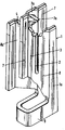
제1도는 2중접점 접속요소가 삽입된 접속 스트립의 부분 단면도.1 is a partial cross-sectional view of a connecting strip with a double contact connecting element inserted therein.
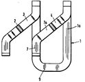
제2도는 제1도의 실시예의 횡단면도.2 is a cross sectional view of the embodiment of FIG.
제3도는 2중접점 접속요소를 도시한 도면.3 shows a double contact connection element.
제4도는 제3도의 접속요소의 평면도.4 is a plan view of the connecting element of FIG.
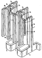
제5도는 다중접점 접속요소를 도시한 도면.5 shows a multi-contact connection element.
제6도는 제5도의 접속요소의 평면도.6 is a plan view of the connecting element of FIG.
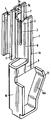
제7도는 일체로 형성된 연장부를 갖는 2중접점 접속요소를 도시한 도면.7 shows a double contact connecting element with an integrally formed extension.
제8도는 삽입식 연장부를 갖는 2중접점 접속요소를 도시한 도면.8 shows a double contact connecting element with an insert extension.
* 도면의 주요부분에 대한 부호의 설명* Explanation of symbols for main parts of the drawings
1 : 접속요소 3, 4, 5, 6 : 횡단웨브1:
7 : 보조웨브 8, 8a, 8b, 8c : 접속부7:
9 : U자형 연결부 11 : 접점9: U-shaped connection 11: Contact
12 : 접속스트립 14 : 블레이드12: connection strip 14: blade
16, 16a : 와이어16, 16a: wire
본 발명은 적어도 두개의 슬롯을 포함하며 판형 탄성 접점재료로 형성되는 각 접속요소에 단일 혹은 복수의 와이어를 납땜, 나사체결, 절연제 제거를 필요로 하지 않고 접속하기 위한 복수개의 접속요소를 포함하는 접속용구로서, 확대 입구부로부터 연장되며 날카로운 단부(엣지)에 의해 구획된 상기 슬롯의 주요 부분은 와이어와 접속요소간의 경사 배치폭이 와이어 금속코어 크기보다 작게 되어 있어서 와이어를 슬롯내로 밀어넣을때 와이어 절연재가 박리되고 와이어와 접속요소간에 접속이 이루어지게된 접속용구에 관한 것이다.The present invention includes at least two slots and includes a plurality of connecting elements for connecting a single or a plurality of wires to each connecting element formed of a plate-shaped elastic contact material without the need for soldering, screwing, or removing insulation. As a splice, the main part of the slot, which extends from the enlarged inlet and is defined by a sharp end (edge), has a warp width between the wire and the connecting element that is smaller than the size of the wire metal core so that the wire is pushed into the slot. It relates to a connection tool in which the insulating material is peeled off and a connection is made between the wire and the connection element.
2개의 병렬배치 통신 케이블 와이어 또는 점퍼 와이어를 접속하기 위한 2중접점을 갖는 납땜, 나사체결, 절연재 제거를 요하지 않는 접속용구(약칭 LSA 접속용구 ; LSA는 독일어의“lot”-, Schraub- 및 abisolierfrei에 유래)는 여러가지 형식의 것이 알려져 있다.Soldering, screwing, or double-contact for connecting two parallel-lined communication cable wires or jumper wires. Connections that do not require removal of the insulating material (abbreviated LSA connection elements; Are derived from various forms.
예를들어 독일연방공화국 공개 2,142,850호에서는 적어도 두개의 슬롯을 갖는 접속용구에 하나 혹은 그이상의 절연와이어를 접속하는 전기 커넥터를 도시하며 독일연방공화국 특허 1,765,584호에서는 하나 또는 두개의 절연와이어를, 서로에 대해 탄성을 가지며 와이어 절연재를 제거하기에 적당한 두 접촉아암으로 각각 형성된 두 슬롯을 갖는 하나의 접속용구에 접속하는 접속커넥터를 도시하고 있다.For example, Federal Republic of Germany Publication No. 2,142,850 shows an electrical connector for connecting one or more insulated wires to a connection device having at least two slots, and in Federal Republic of Germany Patent No. 1,765,584 one or two insulated wires are connected to each other. A connecting connector is shown which is connected to one connecting tool having two slots each formed of two contact arms which are elastic with respect to and suitable for removing wire insulation.
이들 공지의 접속용구는 제작비가 비싼 점이나 나란히 배치하는 경우 구조상 큰 접점간극을 필요로 하기 때문에 상당한 스페이스를 요하는 점에서 개량의 여지가 있다.These known connection devices have a room for improvement in that they require a large space because they require a large contact gap due to their high manufacturing cost or when arranged side by side.
독일연방공화국 특허 공개 제2,338,056호는 두개의 슬롯을 포함하며 한쪽 슬롯은 와이어 유지에, 다른 슬롯은 와이어와의 접축에 쓰이는 형식의 것이 제시되어 있다. 이 슬롯은 서로 다른 형상으로 되어 있다.The Federal Republic of Germany Patent Publication No. 2,338,056 includes two slots in which one slot is used for retaining the wire and the other slot is used for contact with the wire. These slots are of different shapes.
이런 접속요소의 결점은 접속스트립내에 조립할때 과도한 스페이스를 요한다는 점이며, 게다가 접촉아암이 강성구조라는 점이다.The drawback of this connection element is that it requires excessive space when assembling in the connection strip, and that the contact arm is a rigid structure.
독일연방공화국 특허 공개 제3,021,798호는 2중 접점을 이루는 V자형 접속요소로서, 접속요소의 각 아암이 별도의 납땜, 나사체결, 절연재 제거가 필요없는 접점을 형성하는 형태의 것으로 되어 있다.The Federal Republic of Germany Patent Publication No. 3,021,798 is a V-shaped connecting element that forms a double contact, each arm of the connecting element forms a form that does not require separate soldering, screwing, insulation removal.
이 2중접점의 결점은 와이어를 접속요소에 차례로 접속시킬 수 없고 접속을 동시에 시킬 수 밖에 없다는 점이다. 평행으로 접속되는 와이어의 간극은 사용한 탄성재료의 벽 두께의 2배의 값을 갖는다. 이 접속요소는 V자형이라는 점과 이에 관련하여 내측 접촉아암 사이가 상호 지지되어 있다는 점 때문에 접속되는 두개의 와이어를 동시에 접속하는데에만 적당하다.The drawback of this double contact is that wires cannot be connected to the connecting elements in turn and they can only be connected at the same time. The gap of the wires connected in parallel has a value twice the wall thickness of the elastic material used. This connection element is suitable only for connecting two wires connected at the same time because of its V-shape and in this connection between the inner contact arms.
따라서 본 발명의 목적은 상술한 결점을 극복하는 것이다.It is therefore an object of the present invention to overcome the above mentioned drawbacks.
본 발명에 따르면 상술한 목적은, 다음과 같이하여 해결된다. 즉, 각 접속요소를 2중접점 혹은 다중 접점으로 구성하고, 접속슬롯이 각각 형성되고 외이어 측에 약 45°각도로 배치된 각 접속요소의 횡단웨브는 서로 평행하게 배치함으로써 적어도 두개의 상호 병렬 배치된 외이어의 간극이 탄성시트(접점)재료 벽두께로 결정되며 각 접속요소의 웨브는 상향 연장되어 그 단부에 유지수단이 제공되어 있다.According to the present invention, the above object is solved as follows. In other words, each connecting element is composed of double or multiple contact points, and the connecting webs are formed in parallel and the transverse webs of the connecting elements arranged at about 45 ° on the outer side of the connecting element are arranged in parallel with each other so that at least two mutually parallel lines are arranged. The gap of the arranged ear is determined by the wall thickness of the elastic sheet (contact) material, and the web of each connecting element extends upwardly and a retaining means is provided at its end.
본 발명의 다른 유리한 실시에는 청구범위 2항이하에 제시되어 있다.Another advantageous embodiment of the invention is set forth below in
본 발명에 따르면 접속요소 하방에 연장부가 일체로 형성되어 있으며 이들 연장부와 한쪽 아암은 접속부재 반쪽을 형성하여 접속요소가 접속 스트립에 조립된 상태에서 과전압방지기 또는 절단플러그, 시험플러그를 삽입할 수 있게 되어 있다.According to the present invention, extensions are integrally formed below the connecting element, and these extensions and one arm form the connecting member half so that an overvoltage protector, a cutting plug, or a test plug can be inserted while the connecting element is assembled to the connecting strip. It is supposed to be.
본 발명에 따른 신규한 접속부재에 의해 달성되는 잇점은 다음과 같다.The advantages achieved by the novel connecting member according to the invention are as follows.
1. 각 와이어당 접속요소의 소요공간이 종래의 구조에 비해 현저히 감소되어 2개의 상호연결 인접 와이어는 탄성접점재료의 벽두께만큼만 격리된다는 점.1. The space required for connecting elements per wire is significantly reduced compared to conventional structures, so that two interconnecting adjacent wires are only isolated by the wall thickness of the elastic contact material.
2. 본 발명의 접속요소는 인접 와이어의 기능에 영향을 주지 않고 와이어를 차례로 접속, 분해할 수 있다는 점.2. The connecting element of the present invention can connect and disassemble wires in sequence without affecting the function of adjacent wires.
본 발명을 이하 도면에 도시한 실시예를 기초로 상세히 설명하기로 한다.The present invention will be described in detail with reference to the embodiments shown in the drawings below.
제1도 및 제2도에 명백히 도시된 바와같이, 접속요소(1)는 접속스트립(12)에 삽입되도록 되어 있다. 와이어축에 대히 약 45°각도로 배치되고 하나의 접속슬롯을 갖는 횡단 웨브(3,4)는 서로 평행으로 배치되어 있으며, 이로써 복수 와이어(16,16a)의 접속을 가능하게 한다. 이는 두 인접 와이어(16,16a)간의 간극을 결정하는 것이 탄성 접속재료의 벽두께뿐이기 때문이다. 게다가, 과전압 방지기 또는 시험 및 분기용 커넥터를 공지형식으로 이용할 수 있고, 이런 목적으로 개구(12a)가 제공된다.As clearly shown in FIGS. 1 and 2, the connecting
제3도 및 제4도는 2중접점(1a)를 갖는 접속요소(1)를 도시한다. 2개의 서로 연결되고 나란히 배치된 와이어는 차례로 접속, 해제할 수 있다. 보조웨브(7)는 상방으로 연장되어 있으며, 그 단부에 유지수단(17a)을 갖고 있어서 접속될 와이어 안내수단으로서의 역활을 한다.3 and 4 show a connecting
접점요소(1)의 두 접촉부재(8,8a)는 하부에서 단면 U자형 연결부재(9)에 결합되어 있다.The two
제5도 및 제6도는 다중접점요소(1b)를 도시한다. 다중접점요소를 이용함으로써 다른 소정수의 와이어를 접속, 분해할 수 있다. 인접 와이어에 영향을 주지 않고 차례로, 또는 동시에 접속 및 분해를 할 수 있다. 또 여기서 각 접촉부재(8,8a,8b,8c)는 U자형 연결부재(9)에 의해 서로 결합되어 있다.5 and 6 show the
제6도에서 명백한 바와같이, 횡단웨브(3,4,5,6)는 서로 평행 배치하는 것이 좋다.As evident in FIG. 6, the
제7도는 본 발명에 따른 접속요소(1)의 하부에 U자형 연장부(10)를 일체로 형성한 것을 도시한 것이며, 이 연장부(10)의 한쪽 다리로 이루어지는 블레이트(10a)는 탄성을 갖고 접점부재(11)의 반쪽을 구성하고 있다.7 shows the U-shaped
접속 스트립(12)(제1도, 제2도)에 삽입하도록 되어 있는 도시하지 않은 과전압 방지기 또는 시험 및 절단 플러그는 이 접점부재(11)에 접촉한다.An overvoltage protector or test and disconnect plug, not shown, which is intended to be inserted into the connecting strip 12 (FIGS. 1 and 2) contacts this
제8도는 다른 실시예를 도시하고 있다. 여기서, 연장부(14)는 독립부품요소로 구성되어 있다. 필요하다면 이 연장부(14)는 접속요소(1) 하부에 제공된 수용부(13)에 삽입할 수 있다.8 shows another embodiment. Here, the extension portion 14 is composed of independent component elements. If necessary, this extension 14 can be inserted into the
이 경우, 연장부에는 접점부재(15)의 반쪽부로서의 역활을 하는 탄성 아암 (14a)이 형성되어 있다.In this case, the
Claims (5)
Applications Claiming Priority (3)
| Application Number | Priority Date | Filing Date | Title |
|---|---|---|---|
| DE317429.8 | 1981-09-19 | ||
| DE3137429A DE3137429C2 (en) | 1981-09-19 | 1981-09-19 | Connection device in a connection strip |
| DE3137429.8 | 1981-09-19 |
Publications (2)
| Publication Number | Publication Date |
|---|---|
| KR840001395A KR840001395A (en) | 1984-04-30 |
| KR890000970B1 true KR890000970B1 (en) | 1989-04-15 |
Family
ID=6142192
Family Applications (1)
| Application Number | Title | Priority Date | Filing Date |
|---|---|---|---|
| KR8203846A KR890000970B1 (en) | 1981-09-19 | 1982-08-26 | A device for making a solderless non-screwed and unstripped single contact or multiple contact at a terminal element |
Country Status (21)
| Country | Link |
|---|---|
| US (1) | US4533196A (en) |
| EP (1) | EP0075150B1 (en) |
| JP (1) | JPS5925341B2 (en) |
| KR (1) | KR890000970B1 (en) |
| AR (1) | AR230123A1 (en) |
| AT (1) | ATE24796T1 (en) |
| AU (1) | AU552094B2 (en) |
| CA (1) | CA1200080A (en) |
| DE (1) | DE3137429C2 (en) |
| DK (1) | DK164618C (en) |
| ES (1) | ES274780Y (en) |
| GB (1) | GB2106727B (en) |
| GR (1) | GR76247B (en) |
| HK (1) | HK42586A (en) |
| IE (1) | IE53733B1 (en) |
| IL (1) | IL66504A (en) |
| IN (1) | IN156240B (en) |
| MY (1) | MY8600445A (en) |
| NO (1) | NO158395C (en) |
| PH (1) | PH19327A (en) |
| ZA (1) | ZA826028B (en) |
Families Citing this family (45)
| Publication number | Priority date | Publication date | Assignee | Title |
|---|---|---|---|---|
| US4684197A (en) * | 1983-09-07 | 1987-08-04 | Allied Corporation | Plug-in connector and contact element for same |
| DE3405998C2 (en) * | 1984-02-20 | 1986-12-18 | Krone Gmbh, 1000 Berlin | Electrical multiple connector |
| US4885521A (en) * | 1985-08-26 | 1989-12-05 | Applied Research & Technology, Inc. | Unique computer power system with backup power |
| DE3601788A1 (en) * | 1986-01-22 | 1987-07-23 | Albert Stewing | Device for the electrical connection of the individual wires or double wires of telecommunications and signal cables |
| DE3614592C1 (en) * | 1986-04-30 | 1987-07-23 | Krone Ag | Terminal block for cable cores, especially telephone cables |
| DE3818497C5 (en) * | 1988-05-31 | 2005-05-25 | Quante Ag | Terminal block for a cable termination unit |
| EP0403864B1 (en) * | 1989-06-15 | 1996-02-21 | Siemens Aktiengesellschaft | Distribution block for telecommunication exchanges with break contacts |
| US5044979A (en) * | 1989-10-12 | 1991-09-03 | The Siemon Company | Connector block and terminal |
| DE4018164C2 (en) * | 1990-06-01 | 1994-02-10 | Krone Ag | Insulation displacement contact |
| US5156557A (en) * | 1990-11-06 | 1992-10-20 | Yazaki Corporation | Electrical interconnection assembly, process of and apparatus for manufacturing the same and wire laying jig therefor |
| NL192314C (en) * | 1991-05-02 | 1997-05-07 | Du Pont Nederland | Connector containing an isolation displacement contact. |
| US5160273A (en) * | 1991-06-24 | 1992-11-03 | Porta Systems Corp. | Connector block assembly |
| US5281163A (en) | 1991-09-23 | 1994-01-25 | Minnesota Mining And Manufacturing Company | Cross connect system for telecommunications systems |
| US5178558A (en) | 1991-09-23 | 1993-01-12 | Minnesota Mining And Manufacturing Company | Cross connect system for telecommunications systems |
| DE9203355U1 (en) * | 1992-03-12 | 1993-07-15 | Grote & Hartmann Gmbh & Co Kg, 5600 Wuppertal | Electrical contact element with insulation displacement terminals |
| JP2596687Y2 (en) * | 1992-07-31 | 1999-06-21 | ホシデン株式会社 | Multi-pole connector |
| US5643004A (en) * | 1992-09-04 | 1997-07-01 | Quante Aktiengesellschaft | Electric connection contact in a single piece |
| DE9211917U1 (en) * | 1992-09-04 | 1992-11-12 | Quante AG, 5600 Wuppertal | One-piece connection contact |
| DE4322383C2 (en) * | 1993-06-29 | 1997-04-03 | Krone Ag | Multiple contact |
| EP0632527B1 (en) * | 1993-06-29 | 1999-01-20 | KRONE Aktiengesellschaft | Connection module |
| FR2709879B1 (en) * | 1993-09-06 | 1995-12-01 | Yves Saligny | Connector with insulation displacement contact members. |
| DE4341152C1 (en) * | 1993-12-02 | 1995-03-16 | Quante Ag | Connecting strip for making contact with conductors without stripping the insulation |
| GB2300763B (en) * | 1995-04-27 | 1999-08-18 | Krone | Electrical connectors |
| US5591045A (en) * | 1995-05-18 | 1997-01-07 | The Whitaker Corporation | Wire connecting system |
| US5820404A (en) * | 1995-07-10 | 1998-10-13 | Sumitomo Wiring Systems, Ltd. | Terminal and cramping connector |
| US6050842A (en) * | 1996-09-27 | 2000-04-18 | The Whitaker Corporation | Electrical connector with paired terminals |
| US6346005B1 (en) * | 1998-01-19 | 2002-02-12 | The Siemon Company | Reduced cross-talk high frequency wiring connection system |
| US6368144B2 (en) | 1998-03-23 | 2002-04-09 | The Siemon Company | Enhanced performance modular outlet |
| US6126476A (en) * | 1998-03-23 | 2000-10-03 | The Siemon Company | Enhanced performance connector |
| US6083052A (en) | 1998-03-23 | 2000-07-04 | The Siemon Company | Enhanced performance connector |
| US6398580B2 (en) | 2000-01-11 | 2002-06-04 | Visteon Global Tech., Inc. | Electrical terminal member |
| AU785141B2 (en) * | 2000-04-11 | 2006-10-05 | Adc Communications (Australia) Pty Limited | Z-shaped insulation displacement contact |
| AUPQ684300A0 (en) * | 2000-04-11 | 2000-05-11 | Krone (Australia) Technique Pty Limited | Z form insulation displacement contact |
| US20040171295A1 (en) * | 2003-02-27 | 2004-09-02 | Michael Canning | Wire retention device with insulation displacement contacts |
| US7182649B2 (en) * | 2003-12-22 | 2007-02-27 | Panduit Corp. | Inductive and capacitive coupling balancing electrical connector |
| US7399197B2 (en) * | 2004-09-15 | 2008-07-15 | 3M Innovative Properties Company | Connector assembly for housing insulation displacement elements |
| US7101216B2 (en) * | 2004-09-15 | 2006-09-05 | 3M Innovative Properties Company | Insulation displacement system for two electrical conductors |
| US7335049B2 (en) * | 2004-09-15 | 2008-02-26 | 3M Innovative Properties Company | Connector assembly for housing insulation displacement elements |
| US7458840B2 (en) * | 2004-09-15 | 2008-12-02 | 3M Innovative Properties Company | Cap configured to removably connect to an insulation displacement connector block |
| US7165983B1 (en) | 2005-12-08 | 2007-01-23 | 3M Innovative Properties Company | Access cover configured to receive a testing device |
| TWI297559B (en) * | 2006-03-06 | 2008-06-01 | 3M Innovative Properties Co | Cross connect terminal block |
| US7530836B2 (en) * | 2007-04-30 | 2009-05-12 | 3M Innovative Properties Company | Cap for telecommunications cross connect block |
| WO2009029398A1 (en) * | 2007-08-24 | 2009-03-05 | 3M Innovative Properties Company | Termination tool, insulation displacement connector (idc) block and method for electrically connecting an electrical conductor to an idc block |
| DE102008013317B4 (en) * | 2008-03-10 | 2010-10-14 | Adc Gmbh | Method for producing a wire connection strip with gel filling |
| US7985094B2 (en) * | 2008-09-15 | 2011-07-26 | Adc Gmbh | Connector block |
Family Cites Families (16)
| Publication number | Priority date | Publication date | Assignee | Title |
|---|---|---|---|---|
| TR17786A (en) * | 1968-02-16 | 1976-09-01 | Northern Electric Co | INSULATION STRIPPING LINING |
| DE1765584C2 (en) * | 1968-06-14 | 1972-03-30 | Krone Kg | Electrical clamp connection between an insulated wire or two insulated wires and a connection element |
| DE2142850C3 (en) * | 1971-08-26 | 1974-01-03 | Krone Gmbh, 1000 Berlin | Electrical clamp connection device for connecting one or more insulated wires to a connection element |
| US3824527A (en) * | 1972-08-03 | 1974-07-16 | Amp Inc | Wire-in-slot electrical connections |
| FR2272507B1 (en) * | 1974-05-22 | 1978-01-27 | Amp Inc | |
| US3957335A (en) * | 1974-07-26 | 1976-05-18 | Reliable Electric Company | Terminal block assembly |
| AR208483A1 (en) * | 1975-11-10 | 1976-12-27 | Amp Inc | ELECTRICAL TERMINAL |
| US4030799A (en) * | 1976-02-09 | 1977-06-21 | A P Products Incorporated | Jumper connector |
| US4002391A (en) * | 1976-03-03 | 1977-01-11 | Northern Electric Company, Limited | Insulation slicing terminal |
| DE2725551C2 (en) * | 1977-06-07 | 1983-11-17 | Krone Gmbh, 1000 Berlin | Electrical clamp connector |
| DE2804478C2 (en) * | 1978-01-31 | 1982-11-25 | Krone Gmbh, 1000 Berlin | Electrical clamp connector for the production of a contact on a fixed connection element without soldering, screwing or stripping, in particular for telecommunication line technology |
| DE2814069C3 (en) * | 1978-03-30 | 1982-03-25 | Krone Gmbh, 1000 Berlin | Device and method for producing a contact free of soldering, screwing and stripping on a fixed connection element, in particular for telecommunications line technology |
| DE2854681B2 (en) * | 1978-12-18 | 1980-10-16 | Siemens Ag, 1000 Berlin Und 8000 Muenchen | Contact arrangement for ribbon cables |
| US4274696A (en) * | 1979-11-23 | 1981-06-23 | Amp Incorporated | Electrical connecting device for wiring systems |
| DE3021798C2 (en) * | 1980-06-11 | 1982-03-11 | Krone Gmbh, 1000 Berlin | Device and method for producing a double contact on a clamp connector that does not require soldering, screwing or stripping |
| DE3044888C2 (en) * | 1980-11-28 | 1984-09-06 | Krone Gmbh, 1000 Berlin | Free-standing, attachable connection element in Z-shaped design of an LSA-PLUS contact |
-
1981
- 1981-09-19 DE DE3137429A patent/DE3137429C2/en not_active Expired
-
1982
- 1982-08-04 NO NO822662A patent/NO158395C/en unknown
- 1982-08-05 DK DK351582A patent/DK164618C/en not_active IP Right Cessation
- 1982-08-10 AU AU87035/82A patent/AU552094B2/en not_active Ceased
- 1982-08-10 IL IL66504A patent/IL66504A/en not_active IP Right Cessation
- 1982-08-11 CA CA000409183A patent/CA1200080A/en not_active Expired
- 1982-08-11 GR GR69020A patent/GR76247B/el unknown
- 1982-08-12 IE IE1959/82A patent/IE53733B1/en not_active IP Right Cessation
- 1982-08-18 AR AR290329A patent/AR230123A1/en active
- 1982-08-19 ZA ZA826028A patent/ZA826028B/en unknown
- 1982-08-19 US US06/409,370 patent/US4533196A/en not_active Expired - Lifetime
- 1982-08-26 KR KR8203846A patent/KR890000970B1/en active
- 1982-08-27 IN IN999/CAL/1982-BA patent/IN156240B/en unknown
- 1982-09-01 AT AT82108047T patent/ATE24796T1/en active
- 1982-09-01 EP EP82108047A patent/EP0075150B1/en not_active Expired
- 1982-09-06 PH PH27831A patent/PH19327A/en unknown
- 1982-09-08 GB GB08225552A patent/GB2106727B/en not_active Expired
- 1982-09-13 ES ES1982274780U patent/ES274780Y/en not_active Expired
- 1982-09-17 JP JP57162077A patent/JPS5925341B2/en not_active Expired
-
1986
- 1986-06-05 HK HK425/86A patent/HK42586A/en not_active IP Right Cessation
- 1986-12-30 MY MY445/86A patent/MY8600445A/en unknown
Also Published As
| Publication number | Publication date |
|---|---|
| DE3137429C2 (en) | 1984-03-22 |
| NO822662L (en) | 1983-03-21 |
| US4533196A (en) | 1985-08-06 |
| JPS5873969A (en) | 1983-05-04 |
| JPS5925341B2 (en) | 1984-06-16 |
| IL66504A0 (en) | 1982-12-31 |
| GB2106727A (en) | 1983-04-13 |
| DK351582A (en) | 1983-03-20 |
| GR76247B (en) | 1984-08-04 |
| ATE24796T1 (en) | 1987-01-15 |
| CA1200080A (en) | 1986-02-04 |
| KR840001395A (en) | 1984-04-30 |
| IL66504A (en) | 1987-09-16 |
| ZA826028B (en) | 1983-07-27 |
| AR230123A1 (en) | 1984-02-29 |
| ES274780U (en) | 1984-01-16 |
| AU8703582A (en) | 1983-05-12 |
| DE3137429A1 (en) | 1983-04-07 |
| EP0075150A2 (en) | 1983-03-30 |
| IE53733B1 (en) | 1989-02-01 |
| NO158395B (en) | 1988-05-24 |
| PH19327A (en) | 1986-03-18 |
| EP0075150A3 (en) | 1985-05-15 |
| ES274780Y (en) | 1984-09-01 |
| IE821959L (en) | 1983-03-19 |
| DK164618C (en) | 1992-12-07 |
| MY8600445A (en) | 1986-12-31 |
| GB2106727B (en) | 1985-11-27 |
| DK164618B (en) | 1992-07-20 |
| AU552094B2 (en) | 1986-05-22 |
| NO158395C (en) | 1988-08-31 |
| EP0075150B1 (en) | 1987-01-07 |
| HK42586A (en) | 1986-06-13 |
| IN156240B (en) | 1985-06-08 |
Similar Documents
| Publication | Publication Date | Title |
|---|---|---|
| KR890000970B1 (en) | A device for making a solderless non-screwed and unstripped single contact or multiple contact at a terminal element | |
| US4547034A (en) | Device for connecting insulated wires to twin-terminal contact elements | |
| US4322120A (en) | Plug-in connector with improved spring contact | |
| US7717732B2 (en) | Plug-in connector for printed circuits | |
| KR100385805B1 (en) | Connector modules | |
| US4582377A (en) | Cross connection link for modular terminal blocks | |
| KR100379593B1 (en) | Connector module with test and jumper access | |
| EP0670616A1 (en) | Connector for a cable for high frequency signals | |
| US8016617B2 (en) | Wire connection module | |
| KR950034903A (en) | Electrical terminals and coupling connectors | |
| US7762833B2 (en) | Contact element for a plug-type connector for printed circuit boards | |
| KR970031092A (en) | Telecommunications Connectors | |
| US7828584B2 (en) | Plug-type connector for printed circuit boards | |
| KR910006166B1 (en) | Attaching device of communication cable wire | |
| US20080305661A1 (en) | Grounding comb, in particular for a plug-type connector for printed circuit boards | |
| KR960006145A (en) | Flat cable with conductor end connectable to the connector | |
| KR19990071582A (en) | 110-type wire connection block | |
| US4410225A (en) | Universal connector kit | |
| US20100216330A1 (en) | Plug-in connector for a printed circuit board | |
| US3277426A (en) | Cable connectors and methods for the manufacture thereof | |
| US5330367A (en) | Cutting and clamping terminal element | |
| KR100450335B1 (en) | Electrical distribution duct with transmission bus | |
| CA1075788A (en) | Printed circuit board edge connector | |
| US4561712A (en) | Versatile electric connector | |
| KR910004799B1 (en) | Socket connector |