KR890000785B1 - Color correction apparatus for a duplicate camera - Google Patents
Color correction apparatus for a duplicate camera Download PDFInfo
- Publication number
- KR890000785B1 KR890000785B1 KR1019810003433A KR810003433A KR890000785B1 KR 890000785 B1 KR890000785 B1 KR 890000785B1 KR 1019810003433 A KR1019810003433 A KR 1019810003433A KR 810003433 A KR810003433 A KR 810003433A KR 890000785 B1 KR890000785 B1 KR 890000785B1
- Authority
- KR
- South Korea
- Prior art keywords
- color
- color correction
- correction amount
- setting device
- amount setting
- Prior art date
Links
Images


Classifications
-
- G—PHYSICS
- G03—PHOTOGRAPHY; CINEMATOGRAPHY; ANALOGOUS TECHNIQUES USING WAVES OTHER THAN OPTICAL WAVES; ELECTROGRAPHY; HOLOGRAPHY
- G03B—APPARATUS OR ARRANGEMENTS FOR TAKING PHOTOGRAPHS OR FOR PROJECTING OR VIEWING THEM; APPARATUS OR ARRANGEMENTS EMPLOYING ANALOGOUS TECHNIQUES USING WAVES OTHER THAN OPTICAL WAVES; ACCESSORIES THEREFOR
- G03B27/00—Photographic printing apparatus
- G03B27/72—Controlling or varying light intensity, spectral composition, or exposure time in photographic printing apparatus
- G03B27/73—Controlling exposure by variation of spectral composition, e.g. multicolor printers
- G03B27/735—Controlling exposure by variation of spectral composition, e.g. multicolor printers in dependence upon automatic analysis of the original
-
- G—PHYSICS
- G03—PHOTOGRAPHY; CINEMATOGRAPHY; ANALOGOUS TECHNIQUES USING WAVES OTHER THAN OPTICAL WAVES; ELECTROGRAPHY; HOLOGRAPHY
- G03F—PHOTOMECHANICAL PRODUCTION OF TEXTURED OR PATTERNED SURFACES, e.g. FOR PRINTING, FOR PROCESSING OF SEMICONDUCTOR DEVICES; MATERIALS THEREFOR; ORIGINALS THEREFOR; APPARATUS SPECIALLY ADAPTED THEREFOR
- G03F3/00—Colour separation; Correction of tonal value
- G03F3/10—Checking the colour or tonal value of separation negatives or positives
- G03F3/101—Colour or tonal value checking by non-photographic means or by means other than using non-impact printing methods or duplicating or marking methods covered by B41M5/00
Abstract
Description
제1도는 본 발명의 제1실시예의 색 보정장치의 개략도.1 is a schematic diagram of a color correction device according to a first embodiment of the present invention.
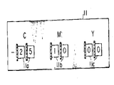
제2도는 제1도의 장치에 사용되는 색 보정량 설정장치의 일예를 나타내는 정면도.2 is a front view showing an example of a color correction amount setting device used in the apparatus of FIG.
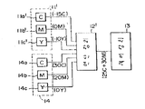
제3도는 본 발명의 제2실시예의 색 보정장치의 요부 블록도.3 is a main block diagram of a color correction apparatus according to a second embodiment of the present invention.
제4도는 제3도의 장치에 사용되는 표준 색 보정량의 설정장치 및 주관적 색 보정량 설정장치의 일예를 나타내는 정면도.4 is a front view showing an example of a standard color correction amount setting device and a subjective color correction amount setting device used in the apparatus of FIG.
* 도면의 주요부분에 대한 부호의 설명* Explanation of symbols for main parts of the drawings
1 : 감광재료 2 : 필름홀더1: photosensitive material 2: film holder
3 : 백색광원 4 : 광측3: white light source 4: light side
5 : 렌즈 6 : 셔터5: lens 6: shutter
7 : 칼라원화 8, 9, 10 : 모터7:
11 : 색보정량 설정장치 11' : 주관적 색 보정량 설정장치11: color correction amount setting device 11 ': subjective color correction amount setting device
11a,11b,11c,11a',11b',11c' : 단위설정장치 12,12' : 연산장치11a, 11b, 11c, 11a ', 11b', 11c ':
13 : 제어장치 14 : 표준 색 보정량 설정장치13
14a,14b,14c : 단위설정장치 50C,50M,50Y : 색보정필터14a, 14b, 14c:
본 발명은 칼라 복사카메라에 있어서, 칼라원화에서 제거하려하는 색의 종류와 그의 농도값을 장치에 설정하는 것 만으로서, 필요한 색 보정을 할 수 있게한 색 보정장치에 관한 것이다.BACKGROUND OF THE INVENTION 1. Field of the Invention The present invention relates to a color correction apparatus in which a color copy camera can perform necessary color correction only by setting the type of color to be removed from the color originalization and its density value in the apparatus.
종래의 칼라복사카메라에 있어서의 색 보정장치에는 빛의 3원색에 대응하는, 예컨대, 시안(C), 마젠타(E), 엘로우(Y)등 3종류의 색 보정필터를 감광재료와 광원사이의 노광광로중에 선택적으로 개재시키게 한 것이었다.(특원소 54-53506)The color correction apparatus in the conventional color radiation camera includes three types of color correction filters corresponding to three primary colors of light, for example, cyan (C), magenta (E), and yellow (Y). It was made to selectively interpose in the exposure optical path. (Special element 54-53506)
그러나, 종래의 그러한 장치에 있어서는 노광광로중에 개재시킬 색 보정필터의 색의 종류와, 그의 농도값(통상 0으로부터 50까지를 5등분으로 표시한 농도단계가 있음)을 설정장치에 설정하여, 그에 대응하는 색 보정필터가 노광광로중에 자동적으로 이동하게끔 구성으로 되어 있기 때문에, 실제로 색 보정을 하는 경우, 우선 색 판별기로서 원화의 색의 치우침을 판별하여, 원화중에서 제거해야될 색의 종류와 그의 농도값을 결정한 후, 그것을 보색으로 환산하여, 즉, 노광광로중에 개재시킬 색 보정필터의 색과 그의 농도값으로 환산하여, 설정장치에 설정해야만 되는 결점이 있었다.However, in such a conventional apparatus, the type of color of the color correction filter to be interposed in the exposure light path and its density value (usually there are density steps in which 0 to 50 are divided into 5 equal parts) are set in the setting device, and Since the corresponding color correction filter is configured to automatically move in the exposure light path, when actually performing color correction, the color discriminator is first used to determine the bias of the original color, and the type of color to be removed from the original and its After determining the density value, it was converted into complementary color, that is, the color of the color correction filter to be interposed in the exposure light path and the density value thereof, which had to be set in the setting device.
예컨대, 색 판별기를 보고,원화중에서 시안(C)을 농도값 20정도를 제거시키고자 하는 경우, 종래의 장치에 있어서는, 그것을 그의 보색, 즉, 마젠타(M)의 엘로우(Y)로 환산하여, 20M+20Y의 농도로 하여 장치에 설정해야만 되었다.For example, in the case of looking at a color discriminator and removing cyanide (C) by about 20 from the concentration, in the conventional apparatus, it is converted into its complementary color, that is, yellow (Y) of magenta (M), The apparatus had to be set at a concentration of 20M + 20Y.
이렇게 원화중에서 제거해야될 색의 종류와 그의 농도값을 그의 보색을 환산하여 설정해야만 된다는 것은 취급인으로서 극히 괴로운 일이며, 또 조작착오의 원인으로도 되어왔던 것이다.This kind of color to be removed from the original painting and its concentration value must be set in terms of its complementary color is extremely painful for the handling agent and has also been a cause of error in operation.
본 발명은, 칼라원화에서 제거해야될 색의 종류와 농도값을 그대로 장치에 설정하는 것만으로, 그에 대하여 보색을 하는 색 보정필터가 노광광로중에 자동적으로 이동하게끔 하는 것으로서, 상술한 바와같은 종래장치에 있어서의 결점을 제거하게끔 한 칼라 복사카메라의 색 보정장치를 제공하는데 목적이 있으며,이하 첨부도면에 나타난 실시예의 의거하여 설명하면 다음과 같다.The present invention merely sets the type and density value of the color to be removed in the color originalization as it is to the device so that the color correction filter which complements the color is automatically moved in the exposure light path. It is an object of the present invention to provide a color correction apparatus for a color copy camera to eliminate the drawbacks in the following description.
제1도 및 제2도는 본 발명의 제1실시예를 나타낸다. (1)은, 필름홀더(2)에 장착된 칼라 복제필름(color duplicate flim)등의 감광재료, (3)은 감광재료 (1)를 노광시키기 위한 백색광원(이하 광원이라 칭함), (4)는 그의 광축이다. 감광재료(1)와 광원 (3)사이에 있는 광축(4)상의 중간에는, 렌즈(5)와 셔터(6)가 상호 근접하여 설치되어 있다. 렌즈(5)와 광원(3)사이에 있는 광축(4)상에는 칼라원화(7)가 장착되어 있다. 칼라원화(7)와 광원(3)과의 사이에는 최고농도의 시안, 마젠타, 엘로우의 각 색의 복정필터(이하, 단지필터라 칭함)(50C)(50M)(50Y)가 그들에게 연계된 구동장치를 이루는 각 모터(8)(9)(10)의 작동에 의하여 서로 독립적으로 광축(4)내에 돌입할 수 있거나(그의 상태를 제1도에 상상선으로 나타냈음) 또는 광축(4)로부터 떨어진 위치로 되돌아오게끔(그의 상태를 제1도에 실선으로 나타냈음) 설치되어 있다.1 and 2 show a first embodiment of the present invention. (1) is a photosensitive material such as a color duplicate flim attached to the film holder (2), (3) a white light source (hereinafter referred to as a light source) for exposing the photosensitive material (1), (4 ) Is his optical axis. In the middle of the optical axis 4 between the photosensitive material 1 and the light source 3, the
더우기, 제1도에 있어서는, 각 필터(50C)(50M)(50Y)와 모터(8)(9)(10)와의 관계는 단순히 선도적으로 간략히 표시되어 있지만, 예컨대, 각 모터(8)(9)(10)를 가역모터로하여 그의 회전축에 고정된 나사봉(도시되지 않았음)의 나사보냄 작용에 의하여, 각 필터(50C)(50M)(50Y)를 상·하 이동시킬 수 있는 연결로 하거나, 각모터(8) (9)(10)의 회전축에 고정설치된 피니언(도시하지 않음)을 각 필터(50C)(50M) (50Y)의 바로 옆에 고정설치된 상·하방향의 랙에 치합시켜, 모터(8)(9)(10)의 정·역회전(正·逆回轉)으로서 필터(50C)(50M)(50Y)를 상하로 움직이게 하는 등 공지의 연결수단을 이용할 수 있는 것이다.Moreover, in FIG. 1, although the relationship between each
또, 모터(8)(9)(10)에 의하지 않고, 예컨대, 솔레노이드등의 다른 구동수단에 의하여, 각 필터(50C)(50M)(50Y)를 광축(4)상에 돌입시키거나, 광축(4)로부터 떨어진 위치로 물러가게 해도 좋다.In addition, each
(11)은 색 보정량 설정장치로서, 칼라원화(7)의 색조로부터 제거할 시안(C), 마젠타(M), 옐로우(Y)의 각색에 대한 농도값을 설정하기 위한 단위설정 장치(11a) (11b)(11c)를 구비하고 있다. 이 색 보정량 설정장치(11)에 있어서의 각 단위설정장치(11a)(11b)(11c)는, 예컨대 제2도에 나타낸 바 있는 10진 표시식 디지탈 스윗치로 할 수 있는 것이다.(11) is a color correction amount setting device, which is a unit setting device (11a) for setting density values for each color of cyan (C), magenta (M), and yellow (Y) to be removed from the color tone of the color originalization (7). (11b) (11c) is provided. Each unit setting device 11a, 11b, 11c in the color correction amount setting device 11 can be, for example, a decimal display type digital switch as shown in FIG.
각 단위설정장치(11a)(11b)(11c)는 각기 연산장치(12)에 접속되어 있다. 연산장치(12)는 다음과 같은 연산을 하는 비교적 간단한 계산회로를 가지고 있다.Each unit setting device 11a, 11b, 11c is connected to the
즉, 연산장치(12)에 있어서는, 각 보정량 설정장치(11)에 설정된 각 색의 농도값을 부(負)의 값으로 하여 입력하여, 그들 농도값중, 최소의 농도값을 다른색의 농도값으로부터 감산하여, 그 농도값의 차에 해당하는색 보정신호로서 출력한다.That is, in the
예컨대, 제2도에 나타낸 바와같이, 시안(C) 의 농도값이 25, 마젠타(M)의 농도값이 10, 예로우(Y)의 농도값이 0(이하, 25C, 10M, 0Y와 같이 표시함)으로하여 설정된 경우, 농도값 25C,10M,0Y를 부(負)의 값으로 하여 (-25C, -10M, -0Y)입력시켜, 그들 농도값중 최소의 농도값(-25)을, 다른색(M)(Y)의 농도값(-10)(-0)에서 감산하여 ((-10)-(-25),(0-25)) 해당 다른색(M)(Y)과 그 차이의 농도값(15) (25)를 색 보정신호(이하, 15M+25Y와 같이 표시함)로 하여 출력한다.For example, as shown in FIG. 2, the concentration value of cyan (C) is 25, the concentration value of magenta (M) is 10, and the concentration value of Yarrow (Y) is 0 (hereinafter, 25C, 10M, 0Y). Display)), enter the concentration values 25C, 10M, 0Y as negative values and input (-25C, -10M, -0Y) to enter the minimum concentration value (-25) among those concentration values. , Subtract from the density value (-10) (-0) of the other color (M) (Y) ((-10)-(-25), (0-25)) and the other color (M) (Y) The density values 15 and 25 of the difference are output as color correction signals (hereinafter referred to as 15M + 25Y).
제어장치(13)는 연산장치(12)의 출력단자에 접속되어, 색 보정신호(상기의 예에서는 15M+25Y)에 입각하여, 이 신호가 나타내는 색(M)(Y)과 대응하는 필터 (50M)(50Y)의 모터(9)(10)를 작동시켜, 그 필터(50M)(50Y)를 신호가 표시하는 농도값(15)(25)에 상당하는 시간만큼 광축(4)상에 개재시킴과 동시에, 셔터(6)의 개폐시기 및 광원(3)의 점등시기를 제어하여, 색 보정신호(15M+25Y)가 지시하는대로 색 보정을 이루게 할 감광재료(1)의 분활노광을 자동적으로 행하게끔 한 것이다.The
이러한 제어장치(13)는, 본 출원인에 의한 일본특허출원(특원소 54-53506)의 명세서중에 전자 제어장치로서 개진되어 있다. 이 제어장치(13)자체의 구성에 대하여는, 본 발명과는 직접 관계가 없기 때문에 그의 요점만을 설명한다.Such a
제어장치(13)는, 감광재료(1)에 대한 배색 빛만에 의한 최적 노광시간(T0), 각종 농도단계에 있어서의 색보정필터의 특성에 관한 정보등을 기억하는 기억장치(도시하지 않았음)을 갖추고 있으며, 연산장치(12)로부터 주어진 색 보정신호(15M+25Y)와 상기의 정보에 입각하여, 백색 빛만에 의한 분할 노광시간(T1)과, 보정량이 가장 큰 색(Y)이 필터(50Y)를 백색 및에 겹쳐서 노광하는 분할 노광시간(T2)고, 보정해야될 2색(M)(Y)의 필터(50M)(50Y)를 백색 빛에 겹쳐 노광하는 분할 노광시간(T3)과의 최적치를 연산하여 구해서, 그들수치에 입각하여 광원(3), 셔터(6), 모터(8)(9)(10)를 제어하는 감광재료(1)을 노광한다.The
즉, 분할 노광시간(T1)에서는 백색빛만에 의하여 감광재료(1)를 노광하며, 분할 노광시간(T2)에서는 보정량이 가장 큰 색인 예로우(Y)의 필터(50Y)의 모터(10)를 작동시켜 그 필터(50Y)를 광축(4)상에 이동시켜 감광재료(1)를 노광시키며, 또, 분할 노광시간(T3)에서는 보정량이 두번째로 큰 색인 마젠타(M)의 필터(50M)의 모터(9)를 작동시켜, 그 필터(50M)와 이미 광축상에 있는 필터(50Y)와를 광축상에 위치시켜 감광재료(1)를 노광하는 것에 의하여, 색 보정신호(15M+25Y)에 표시된 농도값의 색 보정필터(15M)(25Y)를 전 노광시간동안 광축상에 개재시켜 노광한 경우와 동일한 색 보정효과를 얻게끔 한 것이다.That is, in the divided exposure time T 1 , the photosensitive material 1 is exposed only by white light, and in the divided exposure time T 2 , the motor of the
이상의 구성중, 기구부분(부호(1)-(10)으로 표시한 부분)과 제어장치(13)는 상기의 일본특허출원의 발명에 관계되는 것으로, 본 발명에 있어서는, 필요로 하는 색 보정량을, 종래 관용되어 오듯이, 감광재료의 전노광시간중 광축상에 1종류 또는 2종류의 소망 농도값의 색 보정필터를 개재시켜 색 보정을 초래시킬 노광을 행하는 경우에 있어서와 같은 필터의 색과 그 소망 농도값과의 지정방식으로 결정하는 것만으로, 간단히 적절한 분할노광을 행할 수 있다는 잇점이 있는 것이다.In the above structure, the mechanism part (part shown by code | symbol (1)-(10)) and the
이에 대하여, 본 발명은, 상기 일본출원 발명의 구성만으로는, 색 보정량을 설정하는데 있어, 광축(4)상에 개재할 필터의 색과 그의 농도값을 가지고 정하지 않으면 안되며, 그 때문에, 칼라원화(7)의 색조에서 제거해야될 색과 그의 농도값을 보색으로 환산하지 않으면 안되어지만, 상기 색 보정량 설정장치(11) 및 연산장치(12)의 구성에 의하여, 이러한 환산을 하는일 없이, 칼라원화(7)의 색조에서 제거해야 될 색과 그의 농도값을 직접 장치에 설정할 수 있게끔 한 것이다.In contrast, in the present invention, only in the configuration of the above-described Japanese application, in setting the amount of color correction, the color of the filter to be interposed on the optical axis 4 and its density value must be determined. The color to be removed from the color tone and the density value thereof must be converted into complementary colors. However, the color correction amount can be changed without the conversion by the configuration of the color correction amount setting device 11 and the
따라서, 본 발명에 의하면, 작업인이 색 판별기로서 칼라원화의 색이 짜임새를 판별하여, 그 판별한 색의 짜임새를 그대로의 형태로, 예컨대, 칼라원화(7)중에 시안 (C)이 농도값25만큼 센 것으로 느꼈을 경우에는, -25C의 형태로, 색 보정량을 장치에 설정할 수 있으며, 보색을 위한 환산의 번거로움이나, 그런 경우의 환산의 착오에 따른 잘못된 조작을 초래한다는 우려가 없으므로 극히 의의가 큰 것이다.Therefore, according to the present invention, the worker determines the texture of the color original as a color discriminator, and the cyan (C) is concentrated in the color original 7 in the form as it is. If it feels as strong as a value of 25, the color correction amount can be set to the device in the form of -25C, and there is no fear that it will cause the trouble of converting for complementary colors or wrong operation according to the error of such conversion in such a case. Significance is great.
제3도 및 제4도는, 본 발명의 제2실시예를 나타낸다.3 and 4 show a second embodiment of the present invention.
이 제2실시예에 있어서는, 제1실시예에 있어서의 색 보정량 설정장치(11)와 같은 구성의 주관적 색 보정량 설정장치(11')와, 이와 상대를 이루는 표준색 보정량 설정장치(14)를 보유하고 있는 것이다.In this second embodiment, the subjective color correction amount setting device 11 'having the same configuration as that of the color correction amount setting device 11 in the first embodiment, and the standard color correction
주관적 색 보정량 설정장치(11')는 칼라원화(제1도 참조)중의 색 짜임새등 주관적 요인에 의해 색 보정량을, 색의 종류와 그의 농도값으로서 설정하기 위한 것으로서, 각 색(C)(M)(Y)에 대응한 단위설정장치(11a')(11b')(11c')를 비치하고 있다.The subjective color correction amount setting device 11 'is for setting the color correction amount as the kind of color and its density value by subjective factors such as the color texture in the color originalization (see FIG. 1). The unit setting devices 11a ', 11b', and 11c 'corresponding to (Y) are provided.
표준 색 보정량 설정장치(14)는, 감광재료의 특성, 성질등에 의하여 정해지는 기계적 요인에 의한 색 보정량을, 색의 종류와 그 농도값으로서 설정하기 위한 것으로서, 각 색(C)(M)(Y)에 대응하는 단위설정장치(14a)(14b)(14c)를 구비하고 있다.The standard color correction
각 단위설정장치(11a')(11b')(11c')(14a)(14b)(14c)는, 제4도에 표시된 것 같이 10진 표시식 디지탈 스윗치로 할 수 있는 연산장치(12')는, 각 단위설 정장 치(11a')(11b')(11c')(14a)(14b)(14c)에 접촉되어, 다음과 같은 연산을 하여, 그 결과를 색 보정신호로서 출력하는 것이다.Each unit setting device 11a ', 11b', 11c ', 14a, 14b, 14c is an arithmetic unit 12' that can be a decimal display digital switch as shown in FIG. Is in contact with each of the unitary formal values 11a ', 11b', 11c ', 14a, 14b, 14c, performs the following calculation, and outputs the result as a color correction signal.
즉, 연산장치(12')에 있어서는, 표준색 보정량 설정장치(14)에 설정된 각 색(C)(M)(Y)의 농도값으로부터 그 색에 대응하는 주관적 색 보정량 설정장치(11')에 설정된 각 색의 농도값으로 각기 감산하여, 그들 감산치중 최소의 농도값을 다른색의 감산 농도치로부터 다시 감산하여, 당해 다른색과 그 차의 농도값을 색 보정신호로서 출력시킨다.That is, in the computing device 12 ', from the density value of each color C (M) (Y) set in the standard color correction
예컨대, 각 색 보정량 설정장치(11')(14)에 설정된 설정치가, 제4도에 나타낸 바와같이, 표준 설정치가 30C,20M,0Y로서 주관석 설정치가 15C,0M, 10Y인 경우, 우선 표준 설정치로부터 주관적 설정치가 15C,0M,10Y인 경우, 우선 표준 설정치로부터 주관적 설정치를 감산한 수치 15C,20M,-10Y를 구하고, 그들의 감산치중 최소의 농도값 -10을 다른색(C)(M)의 감산농도값 15,20으로부터 다시 감산하여, 당해 다른색 (C)(M)과 그 차의 농도값(25)(30)과를, 색 보정신호(25+30M)로 하여 출력한다.For example, when the set values set in the color correction
제어장치(13)은 제1실시예의 것과 완전히 동일한 것이며, 연산장치(12')로부터 주어진 색 보정신호(상기예에서는 25C+30M)에 입각하여, 제1도에서 나타내는 기구부와 동일한 기구부(도시하지 않았음)을 제어하여, 필요한 분할노광을 행하는 것이다.The
상술한 바와같이, 본 제2실시예에 있어서는, 제1실시예에 있어서의 구성에, 표준 색 보정량 설정장치(14)를 부가한 구성인 것으로 하는 것이다.As described above, in the second embodiment, the standard color correction
이와같은 표준 색 보정량 설정장치(14)는, 상기 특허출원의 명세서중에 개진된 색 보정량 설정장치와 같은 기능을 맡고 있는 것이다.Such a standard color correction
제2실시예에 있어서는, 이와같은 표준 색 보정량 설정장치(14)를 주관적 색 보정량 설정장치(11')와 별도로 설정한 이유는, 칼라 복제필름등의 감광재료에 있어서는, 그 특성에 따라, 미리 그 필요한 색 보정량이 노광광로중에 개재시킬때 색 보정필터의 색과 그 농도값으로서 예컨대 30C+20M의 형태로, 색 보정신호로서 직접 제어장 치(13)에 입력하는 것이 편리하기 때문이다.In the second embodiment, the reason why the standard color correction
만약, 이와같은 표준 색 보정량 설정장치(11')가 없는 상태에서 상술한 바와같은 기게적 요인에 의한 색 보정을 필요로하는 경우, 이미 주어진 색 보정량을 다시 그 보색의 농도값을 환산하여 장치에 설정하도록 되어있다.If there is no such standard color correction amount setting device 11 ', and color correction by the mechanical factors as described above is required, the color correction amount already given is converted into the complementary color density value and converted into the device. It is supposed to be set.
따라서, 이 제2실시예에 있어서는, 감광재료의 특성등에 관련된 기계적 요인에의한 색 보정과, 칼라원화를 육안으로 판단하여, 원화에서 제거시키고 싶은 색이 있는 경우에 있어서의 주관적 요인에 의한 색 보정을 동시에 행하는 경우에 의의가 있는 것이다.Therefore, in this second embodiment, color correction due to mechanical factors related to the characteristics of the photosensitive material and the like, and color due to subjective factors when there is a color to be removed from the original picture by visually judging the color originalization This is meaningful when the correction is performed at the same time.
더우기, 상기양 실시예에 있어서 분할 노광방식에 의하여 감광재료의 노광을 하는 경우의 색 보정장치에 대하여는, 본 발명을 적용한 경우의 것으로 표시했으나, 본 발명은 이와같은 경우에만 한한 것이 아니고, 각종 농도단계의 다수의 색 보정필터를 구비하여, 색 보정신호에 따라, 그 소요 농도값의 색 보정필터를 노광광로중에 빼내며, 전 노광시간중 그 필터를 광축상에 위치시킨 대로 노광하는 노광방식에 있어서의 색 보정장치에도 적용이 가능한 것이다.Furthermore, in the above embodiments, the color correction apparatus in the case of exposing the photosensitive material by the split exposure method is shown as the case where the present invention is applied. However, the present invention is not limited to this case, but various concentrations In the exposure method, a plurality of color correction filters are provided, and the color correction filter of the required density value is taken out of the exposure light path according to the color correction signal, and the exposure is performed as the filter is positioned on the optical axis during the entire exposure time. The present invention can also be applied to a color correction device.
Claims (2)
Applications Claiming Priority (3)
| Application Number | Priority Date | Filing Date | Title |
|---|---|---|---|
| JP55135486A JPS5760352A (en) | 1980-09-29 | 1980-09-29 | Color correction apparatus for color copying camera |
| JP???55-135486 | 1980-09-29 | ||
| JP55-135486 | 1980-09-29 |
Publications (2)
| Publication Number | Publication Date |
|---|---|
| KR830008192A KR830008192A (en) | 1983-11-16 |
| KR890000785B1 true KR890000785B1 (en) | 1989-04-06 |
Family
ID=15152842
Family Applications (1)
| Application Number | Title | Priority Date | Filing Date |
|---|---|---|---|
| KR1019810003433A KR890000785B1 (en) | 1980-09-29 | 1981-09-15 | Color correction apparatus for a duplicate camera |
Country Status (9)
| Country | Link |
|---|---|
| US (1) | US4375918A (en) |
| JP (1) | JPS5760352A (en) |
| KR (1) | KR890000785B1 (en) |
| DE (1) | DE3134176A1 (en) |
| DK (1) | DK156020C (en) |
| ES (1) | ES8206867A1 (en) |
| FR (1) | FR2491222A1 (en) |
| GB (1) | GB2084747B (en) |
| IT (1) | IT1138238B (en) |
Families Citing this family (9)
| Publication number | Priority date | Publication date | Assignee | Title |
|---|---|---|---|---|
| GB8420483D0 (en) * | 1984-08-11 | 1984-09-12 | Hester R E | Colour correction head |
| US4603965A (en) * | 1985-06-28 | 1986-08-05 | Cook Kenneth O | Apparatus and method for making color photographic prints |
| JPH0612402B2 (en) * | 1985-11-05 | 1994-02-16 | コニカ株式会社 | Color copier |
| JP2523479B2 (en) * | 1985-11-11 | 1996-08-07 | 株式会社日立製作所 | Light control device for camera |
| US4984012A (en) * | 1987-10-23 | 1991-01-08 | Brother Kogyo Kabushiki Kaisha | Color image copying apparatus |
| US4924255A (en) * | 1987-12-18 | 1990-05-08 | Brother Kogyo Kabushiki Kaisha | Exposure unit in an image recording apparatus |
| US4965625A (en) * | 1988-12-21 | 1990-10-23 | Brother Kogyo Kabushiki Kaisha | Image forming apparatus having image forming data inputting device |
| US4992828A (en) * | 1989-12-11 | 1991-02-12 | Eastman Kodak Company | Digitizer having selected area designation |
| KR100378492B1 (en) * | 1995-10-27 | 2004-05-20 | 삼성테크윈 주식회사 | Photographic printing device |
Family Cites Families (8)
| Publication number | Priority date | Publication date | Assignee | Title |
|---|---|---|---|---|
| DE1422724A1 (en) * | 1960-12-22 | 1968-11-28 | Gevaert Photo Prod Nv | Color correction system for photographic color copiers |
| DE2535034B2 (en) * | 1975-08-06 | 1978-01-26 | Agfa-Gevaert Ag, 5090 Leverkusen | PHOTOGRAPHIC COLOR COPIER WITH A PHOTOELECTRICALLY CONTROLLED EXPOSURE CONTROL DEVICE |
| JPS52156625A (en) * | 1976-06-22 | 1977-12-27 | Fuji Photo Film Co Ltd | Automatic color printing method utili#ing skin color |
| JPS5312330A (en) * | 1976-07-20 | 1978-02-03 | Fuji Photo Film Co Ltd | Color printer and control of its exposure time |
| CH627288A5 (en) * | 1977-03-11 | 1981-12-31 | Gretag Ag | |
| US4154523A (en) * | 1977-05-31 | 1979-05-15 | Eastman Kodak Company | Exposure determination apparatus for a photographic printer |
| DE2829347A1 (en) * | 1977-07-06 | 1979-01-25 | Gretag Ag | Machine photographic colour printer - has colour assessment and digital correction circuitry and control for subtractive filter unit by photocell integration |
| US4279502A (en) * | 1978-09-15 | 1981-07-21 | Agfa-Gevaert, A.G. | Method of and apparatus for determining the copying light amounts for copying from color originals |
-
1980
- 1980-09-29 JP JP55135486A patent/JPS5760352A/en active Pending
-
1981
- 1981-08-25 GB GB8125847A patent/GB2084747B/en not_active Expired
- 1981-08-28 DE DE19813134176 patent/DE3134176A1/en not_active Withdrawn
- 1981-08-31 US US06/298,342 patent/US4375918A/en not_active Expired - Fee Related
- 1981-09-02 DK DK388581A patent/DK156020C/en not_active IP Right Cessation
- 1981-09-15 KR KR1019810003433A patent/KR890000785B1/en active
- 1981-09-18 FR FR8117625A patent/FR2491222A1/en active Granted
- 1981-09-21 ES ES505664A patent/ES8206867A1/en not_active Expired
- 1981-09-24 IT IT24113/81A patent/IT1138238B/en active
Also Published As
| Publication number | Publication date |
|---|---|
| DK156020C (en) | 1989-11-13 |
| IT8124113A0 (en) | 1981-09-24 |
| ES505664A0 (en) | 1982-08-16 |
| DK388581A (en) | 1982-03-30 |
| IT1138238B (en) | 1986-09-17 |
| GB2084747A (en) | 1982-04-15 |
| ES8206867A1 (en) | 1982-08-16 |
| US4375918A (en) | 1983-03-08 |
| FR2491222B1 (en) | 1985-05-17 |
| DE3134176A1 (en) | 1982-05-06 |
| GB2084747B (en) | 1985-05-09 |
| KR830008192A (en) | 1983-11-16 |
| DK156020B (en) | 1989-06-12 |
| JPS5760352A (en) | 1982-04-12 |
| FR2491222A1 (en) | 1982-04-02 |
Similar Documents
| Publication | Publication Date | Title |
|---|---|---|
| KR890000785B1 (en) | Color correction apparatus for a duplicate camera | |
| US4802107A (en) | Offset drift correction method in color film inspection apparatus | |
| US3120782A (en) | Exposure control system for color printers | |
| US4101217A (en) | Automatic color printing apparatus | |
| US4668979A (en) | Production of color separations for single color printing in which separation hues and colors are optimally defined with respect to hue, color separation, and luminance | |
| GB1594569A (en) | Arrangement for indicating over-correction in electronic colour correction | |
| US4092668A (en) | Correction circuit for a color scanner | |
| US4360255A (en) | Method and apparatus for transmission of information in a photographic camera | |
| JPS5953535B2 (en) | Black spot color signal level adjustment circuit device | |
| US5940169A (en) | Image frame selecting device for photographic printer | |
| EP0162500B1 (en) | A method of and apparatus for generating colour matte signals | |
| US4939537A (en) | Exposure controlling apparatus | |
| US3897250A (en) | Method and apparatus for exposing a light-sensitive layer | |
| EP0128063A1 (en) | Method and apparatus for adjusting the coloured background in a television picture | |
| JPH0151826B2 (en) | ||
| US3161108A (en) | Photographic color reproduction apparatus | |
| US4678740A (en) | Method for making photographic mattes | |
| US4728992A (en) | Process and a device for adjusting a photographic color enlarging or copying apparatus | |
| GB2234359A (en) | Exposure control unit for a motor driven camera shutter | |
| SU1264129A1 (en) | Method and apparatus for producing colour separated pictures | |
| US2972011A (en) | Method for processing a subtractive motion picture film | |
| US2962544A (en) | Method of producing a subtractive color film copy | |
| JP3343302B2 (en) | Exposure equipment | |
| JP2736526B2 (en) | Color film reader | |
| JPH01200348A (en) | Device for determining photographic printing density |