KR890000148B1 - Manually actuated dispenser - Google Patents
Manually actuated dispenser Download PDFInfo
- Publication number
- KR890000148B1 KR890000148B1 KR1019840006210A KR840006210A KR890000148B1 KR 890000148 B1 KR890000148 B1 KR 890000148B1 KR 1019840006210 A KR1019840006210 A KR 1019840006210A KR 840006210 A KR840006210 A KR 840006210A KR 890000148 B1 KR890000148 B1 KR 890000148B1
- Authority
- KR
- South Korea
- Prior art keywords
- accumulator
- plunger
- pump
- chamber
- valve
- Prior art date
Links
Images


Classifications
-
- B—PERFORMING OPERATIONS; TRANSPORTING
- B05—SPRAYING OR ATOMISING IN GENERAL; APPLYING FLUENT MATERIALS TO SURFACES, IN GENERAL
- B05B—SPRAYING APPARATUS; ATOMISING APPARATUS; NOZZLES
- B05B11/00—Single-unit hand-held apparatus in which flow of contents is produced by the muscular force of the operator at the moment of use
- B05B11/0005—Components or details
- B05B11/0062—Outlet valves actuated by the pressure of the fluid to be sprayed
- B05B11/0064—Lift valves
-
- B—PERFORMING OPERATIONS; TRANSPORTING
- B05—SPRAYING OR ATOMISING IN GENERAL; APPLYING FLUENT MATERIALS TO SURFACES, IN GENERAL
- B05B—SPRAYING APPARATUS; ATOMISING APPARATUS; NOZZLES
- B05B11/00—Single-unit hand-held apparatus in which flow of contents is produced by the muscular force of the operator at the moment of use
- B05B11/01—Single-unit hand-held apparatus in which flow of contents is produced by the muscular force of the operator at the moment of use characterised by the means producing the flow
- B05B11/10—Pump arrangements for transferring the contents from the container to a pump chamber by a sucking effect and forcing the contents out through the dispensing nozzle
- B05B11/1042—Components or details
- B05B11/1073—Springs
- B05B11/1074—Springs located outside pump chambers
-
- B—PERFORMING OPERATIONS; TRANSPORTING
- B05—SPRAYING OR ATOMISING IN GENERAL; APPLYING FLUENT MATERIALS TO SURFACES, IN GENERAL
- B05B—SPRAYING APPARATUS; ATOMISING APPARATUS; NOZZLES
- B05B11/00—Single-unit hand-held apparatus in which flow of contents is produced by the muscular force of the operator at the moment of use
- B05B11/01—Single-unit hand-held apparatus in which flow of contents is produced by the muscular force of the operator at the moment of use characterised by the means producing the flow
- B05B11/10—Pump arrangements for transferring the contents from the container to a pump chamber by a sucking effect and forcing the contents out through the dispensing nozzle
- B05B11/1001—Piston pumps
- B05B11/1009—Piston pumps actuated by a lever
- B05B11/1011—Piston pumps actuated by a lever without substantial movement of the nozzle in the direction of the pressure stroke
-
- B—PERFORMING OPERATIONS; TRANSPORTING
- B05—SPRAYING OR ATOMISING IN GENERAL; APPLYING FLUENT MATERIALS TO SURFACES, IN GENERAL
- B05B—SPRAYING APPARATUS; ATOMISING APPARATUS; NOZZLES
- B05B11/00—Single-unit hand-held apparatus in which flow of contents is produced by the muscular force of the operator at the moment of use
- B05B11/01—Single-unit hand-held apparatus in which flow of contents is produced by the muscular force of the operator at the moment of use characterised by the means producing the flow
- B05B11/10—Pump arrangements for transferring the contents from the container to a pump chamber by a sucking effect and forcing the contents out through the dispensing nozzle
- B05B11/1095—Pump arrangements for transferring the contents from the container to a pump chamber by a sucking effect and forcing the contents out through the dispensing nozzle with movable suction side
Abstract
Description
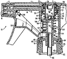
제1도는 분배될 유동체를 담고 있는 콘테이너의 목위에 설치된 디스펜서의 펌프 요소들이 방아쇠 작용전의 정지 위치에서 도시된 본 발명에 따른 디스펜서의 수직 단면도.1 is a vertical cross-sectional view of the dispenser according to the invention in which the pump elements of the dispenser installed on the neck of the container containing the fluid to be dispensed are shown in a stopped position before triggering.
제2도는 흡입밸브가 페쇄되고 토출 밸브가 개방되는 압축 행정의 단 또는 단 부근에서 플린저가 도시된 제1도의 상사도.FIG. 2 is a top view of FIG. 1 showing the plunger at or near the end of the compression stroke where the intake valve is closed and the discharge valve is open.
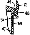
제3도 및 제4도는 콘테이너 통풍구를 밸브로 조정하는 대안적인 배치를 나타내는 제1도에 상사한 디스펜서의 일부분도.3 and 4 are partial views of the dispenser similar to FIG. 1 showing an alternative arrangement for adjusting container vents with valves.
* 도면의 주요부분에 대한 부호의 설명* Explanation of symbols for main parts of the drawings
10 : 디스펜서 11 : 펌프몸체10 dispenser 11: pump body
12 : 원통부 13 : 토출용기12: cylindrical portion 13: discharge container
14 : 토출로 15 : 내부환상벽14
16 : 토출 오리피스 17 : 토출노즐16: discharge orifice 17: discharge nozzle
18 : 핀 19 : 컵18: Pin 19: Cup
21 : 블라인드소켓(blind socket) 37 : 보울체크(ball check)21: blind socket 37: ball check
22 : 리브 23 : 어큐뮬레이터요소22: rib 23: accumulator element
24 : 슬리이브 25, 47 : 스커어트(skirt)24:
26,46 : 숄더 27 : 패킹 누르게26,46: shoulder 27: press the packing
28 : 토출 밸브 29 : 축압실28
31 : 플런저 32 : 피스톤부31: plunger 32: piston
33 : 펌프실 34 : 연장부분33: pump chamber 34: extension part
35 : 흡입로 36 : 딥튜브(dip tube)35: by suction 36: dip tube
38 : 밸브시트 39 : 밸브개구38: valve seat 39: valve opening
41 : 핑거(finger) 42 : 목41: finger 42: neck
43 : 캡 44 : 플랜지43: cap 44: flange
45, 52 : 홈 48 : 통풍구 밸브45, 52: groove 48: vent valve
49 : 통풍구시트 50 : 코일리턴스프링49: air vent sheet 50: coil return spring
51 : 림(rim)51: rim
53 : 플린저 리프트 플랜지(plunger lift flange)53: plunger lift flange
55 : 방아쇠 작동기 59 : 축홈55: trigger actuator 59: shaft groove
본 발명은 일반적으로 소정의 최소 압력 이상으로 축압된 펌프 압력에 의해 토출되는 압력 축압식의 디스펜서에 관한 것이다. 이런 방식의 디스펜서는 미리 결정된 압력으로 유지된 상태로 토출을 요구하는 유동체에 대한 스프레이너로써 종종 사용되어 왔다.The present invention relates generally to pressure accumulators dispensed by pump pressures accumulating above a certain minimum pressure. Dispensers in this manner have often been used as sprayers for fluids that require ejection while maintained at a predetermined pressure.
여기서 설명한 일반적인 부류의 디스펜서는 예를들어 미국 특허원4,046,292및4,050,613등의 종래 특허에서 나타난 바와 같이 종래 기술에서 잘 공지 되었다.The general class of dispensers described herein is well known in the art, as shown, for example, in the prior patents of US Pat. Nos. 4,046,292 and 4,050,613.
본 발명의 목적은 상기 언급한 바와같이 공지의 디스펜서 펌프에 새로운 해결 방안을 제공하는 동시에 부품들의 수를 감소하고 또한 간소화시키는 한편 실제로 적하됨 없이 토출을 성취할 만한 형태의 디스펜서를 위한 조합체를 제공하는데 있다.It is an object of the present invention to provide a combination for a dispenser of a type which, as mentioned above, provides a novel solution to known dispenser pumps while at the same time reducing and simplifying the number of components while at the same time achieving a discharge without dropping. have.
본 발명에 의한 수동식 디스펜서는 분포되어질 유동체를 담고 있는 콘테이너의 개구를 통해 유체가 봉쇄되는 상태로 부착되어 있는 펌프 몸체를 구성하고 있다. 펌프 몸체는 환상의 토출 밸브를 가지는 중공부 슬리이브를 형상의 어큐뮬레이터(accumulator)요소 및 배출구 개폐위치 사이에서의 변위중 어큐뮬레이터를 안내하고 밀봉하기 위한 환상의 패킹 누르개(packing gland)를 갖고 있다.The manual dispenser according to the present invention constitutes a pump body which is attached in a state where fluid is sealed through an opening of a container containing a fluid to be distributed. The pump body has an annular packing gland for guiding and sealing the accumulator during displacement between the shaped accumulator element and the outlet opening and closing position with a hollow sleeve having an annular discharge valve.
체크밸브 베어식 흡입로를 포함하고 있는 중공 플린저는 개방 슬리이브 속으로 연장되는 피스톤부를 가지며, 그와 함께 플런저의 왕복 운동중 펌프 몸체에 힌지로 장치된 방아쇠 작동기(tigger actuator)에 의해 수동적으로 수행될 수 있는 다양한 체적 펌프실을 한정한다.The hollow plunger comprising a check valve bare suction passage has a piston section extending into the open sleeve, which is also performed manually by a trigger actuator which is hinged to the pump body during the reciprocating motion of the plunger. It defines a variety of volumetric pump rooms that can be used.
블라인드 소켓(blind socket)은 펌프 몸체의 일단에 형성되고, 그와 함께 어큐뮬레이터는 펌프실과 직접 서로 통하고 펌프실보다 더 큰 직경을 가진 봉해진 가변성 체적 압력 축압실을 한정한다. 플런저와 어큐뮬레터 사이에서 작용하는 리턴코일 스프링은 유체 긴밀 방편으로 축압실의 외향적으로 연장되는 배출로를 통해 누출되는 것을 방지하기 위하여 블라인드 소켓단에 마련된 하나의 환상 밀봉링 또는 시트에 놓여진 밀봉된 토출 폐쇄위치로 토출 밸브가 정상적으로 탄력성 있게 작용하도록 한다. 스프링은 마찬가지로 콘테이너 통풍구의 폐쇄 및 밀봉된 위치로 플런저가 탄력있게 작용하도록 한다.A blind socket is formed at one end of the pump body, with which the accumulator defines a sealed variable volume pressure accumulator chamber which is in direct communication with the pump chamber and has a larger diameter than the pump chamber. The return coil spring acting between the plunger and the accumulator is a sealed ring placed on a seat or one annular seal ring at the end of the blind socket to prevent leakage through the outwardly extending outlet of the accumulator chamber in a fluid tight way. The discharge valve is normally elastically operated to the discharge closed position. The spring likewise allows the plunger to act elastically in the closed and sealed position of the container vent.
플런저의 피스톤 단은 간극 체적을 최소량으로 감소시키고, 또한 플런저의 왕복 운동을 수행시키는 방아쇠의 간헐적인 작용에 의해 배출이 준비되는 동안 토출구를 통해 펌프실에서 쓸모없는 공기를 청소시키기 위한 고압 축비를 얻는 펌프몸체위의 대응면에 일치하도록 만들어진다. 축압실내의 압력은 플런저의 압축 행정중 증갈하여 리턴 스프링의 탄성 비틀림에 반해 그리고 탄성 비틀림의 초과 상태로 어큐뮬레이터 상에 작용하는 힘을 생성시킨다. 어귤뮬레이터는 따라서 펌프 몸체의 블라인드 소켓단에서 떨어져 이동되고, 토출밸브는 토출로가 열리게끔 떨어져서 펌프실에 내용물이 압력하에서 배출하게 된다. 펌프실의 압력이 스프링의 탄성력에 의해 다시 극복되어 어큐뮬레이터가 토출밸브가 유동체 유동을 폐쇄시키기 위해 다시 앉혀지는 최소의 위치로 귀환하는 때까지 배출은 계속된다. 플런저 흡입 행정의 말단에서, 방아쇠에 대한 핑거 압력(finger pressure)이 해제되기 때문에, 플런저 위에 놓인 콘테이너 통풍구 밸브는 콘테이너 통풍구를 막는다. 그와 같은 통풍구는 밸트 시트로서 기능을 발휘하는 펌프 몸체상의 환상의 컬러에 놓여진 축홈에 의해 한정된다.The piston stage of the plunger reduces the volume of the gap to a minimum amount, and also obtains a high pressure axial ratio for cleaning the useless air in the pump chamber through the discharge port during discharge preparation by the intermittent action of the trigger to perform the reciprocating motion of the plunger. It is made to match the corresponding surface on the body. The pressure in the accumulator chamber is increased during the compression stroke of the plunger to produce a force acting on the accumulator against the elastic torsion of the return spring and in the excess of the elastic torsion. The regulator is thus moved away from the blind socket end of the pump body and the discharge valve is opened to open the discharge passage so that the contents in the pump chamber are discharged under pressure. Discharge continues until the pressure in the pump chamber is overcome again by the spring force and the accumulator returns to the minimum position where the discharge valve is reseated to close the fluid flow. At the end of the plunger suction stroke, because the finger pressure on the trigger is released, a container vent valve over the plunger blocks the container vent. Such vents are defined by shaft grooves placed in an annular color on the pump body that functions as a belt seat.
이와 반대로, 콘테이너 통풍은 축홈에 설비에 의해 수행될 수도 있고, 통풍구 밸브에서 매달려 있는 플런저상의 스커트 내에 있는 관통 개구의 설비에 의해 수행될 수 있다.In contrast, container ventilation may be carried out by means of an arrangement in the shaft groove, or by means of an arrangement of through openings in the skirt on the plunger suspended from the vent valve.
본 발명의 기타 목적, 장점 및 새로운 특징은 첨부된 도면과 관련하여 설명으로부터 더욱 명백해질 것이다.Other objects, advantages and novel features of the invention will become more apparent from the description with respect to the accompanying drawings.
본 도면들은 여러 도면을 통해 상응 부분 및 같은 부분을 겉은 도면부호로 적용되며, 전체적으로 부호10으로 표시된 본 발명에 따른 수동식으로 작동되는 디스펜서는 하나의 원통부(12)을 가지는 펌프 몸체(11), 일단에서 원통부분(12)의 내부의 환상벽(15)으로 개방하는 길이방향의 토출 통로(14)를 갖춘 토출 용기(13)로 구성된다. 토출통로의 종료단은 토출 노즐(17)에 설비된 토출 오리피스(16)와 통하고 있는데, 그 노즐은 토출이 폐쇄되는 위치 내에 있는 용기(13)의 종료 단위에 내뚫려 있다. 용기(13)의 종료단에 있는 핀(18)은 제1도의 토출 폐쇄 위치 내의 토출 오리피스를 둘러싸고 있는 컵(19)안에 놓여 있다. 토출구는 공지된 방식대로 노즐을 빠져 나오므로써 개방되어지며, 컵(19)은 분무를 위한 와류실을 갖고 있다.The figures apply like reference numerals to the corresponding and like parts throughout the several views, and the manually operated dispenser according to the invention, denoted by
펌프 몸체의 부분(12)는 그 일단에 환상의 밀봉리브(22)에 한정된 하방 직선 블라인드 소켓(21)이 마련되도록 만들어진다. 벽(15)을 따라 미끄럼 이동을 위해 몸체부분(12)에 배치된 어큐뮬레이터 요소(23)는 펌프 실린더를 한정하는 개방단을 가진 슬리이브(24)를 구성하고 있는데 그것은 환상의 숄더(26)에 의해 결합된 동심의 스커어트(25)로 둘러싸였다. 스커어트(25)상의 패킹 누르개(27)는 유체조임 방식으로 어큐뮬레이터를 안내하기 위하여 몸체부분(12)의 내부벽(15)에 맞대어 있다. 환상 토출 밸브(28)는 스커어트(25)의 상단 부근에 설비되고 또 제1도의 토출 폐쇄위치 내에서 밀봉 리브(22)에 마주하여 놓여진다.The
상기 설명된 바와 같이 어큐뮬레이터는 블라인드 소켓과 함께 가변성의 체적 압력 축적실(29)을 한정한다.As described above, the accumulator defines a variable volume
중공 플런저(hollow plunger)(31)는 몸체부분(12)내에서 왕복운동을 하기 위해 설치되고, 또한 그 플런저는 그 상단에서 어큐뮬레이터의 슬라이브 속으로 신장하는 피스톤부(32)를 가져서 축압실(29)과 개방 상태로 직접 통하는 가변성의 체적 압력 펌프실(33)을 한정한다. 또한, 플런저의 피스톤 단과 어큐뮬레이터의 숄더는 펌프 몸체상에 있는 펌프 몸체의 구성 확대부분(34)상의 대응면에 형상에 실질적으로 일치 하도록 만들어진다.A
차후 더 상세하게 설명되는 바, 이들 서로 대면하는 표면들을 펌프 작동 효율을 증진시키기 위해 배출 준비를 하기 전에 또한 하는 동안 불필요한 공기를 펌프실로부터 토출 통로를 통해 실제적으로 청소가 되게끔 한다.As will be described in more detail below, these mutually opposing surfaces are allowed to be substantially cleaned through the discharge passage from the pump chamber before and during the preparation of discharge to enhance pump operating efficiency.
플런저는, 연결된 딥 튜우브(dip tube)(36)를 거쳐 플런저 하부에서 토출 되어질 유동체를 담고 있는 콘테이너(도시하지 않음)의 내부와 통하는 흡입로(35)를 구성하고 있다. 흡입로를 통하는 유동체의 유동은 흡입로의 상단에서 밸브개구(39)를 에워싸고 있는 흡입 밸브시트(38)에 대해 정상적으로 얹혀진 보울 체크(37)의 형상인 체크밸브에 의해 조정된다. 쭉 뻗은 손가락(41)모양인 케이지(cage)는 보울 체크를 둘러싸며 또한 설비되지 않았을때는 공지의 방식으로 운동을 제한한다. 물론, 체크밸브는 본 발명에 벗어남이 없이 특허원4,050,613에 기재된 것과 유사한 경첩식 밸브의 형상으로 할수도 있다.The plunger constitutes a
펌프 몸체는 토출될 유동체를 담고 있는 콘테이너의 개구와 유체가 새지 않는 연결상태로 보호되어지도록 응용된다. 이 목적을 위해 내부에 나사가 새겨져 있거나 또는 액체가 새지 않는 방도로 펌프 몸체를 보호하기 위해 배치된 콘테이너 닫힘 캡(43)이 유사하게 나사가 새겨진 콘테이너의 목부분(42)과 접속되고, 또 캡 상단에서 콘테이너 목위에 디스펜서 몸체를 고정하기 위해 몸체부분(12)의 원주 주위에 마련된 접함홈(45)와 접속되는 내향에서 쭉 뻗은 환상의 플랜저(44)를 가진다.The pump body is adapted to be protected from leaking connections with the opening of the container containing the fluid to be discharged. For this purpose the
플러저상의 환상 숄더(46)는 그곳으로부터 매달려 있는 환상의 스커어트(47)를 가지며, 또한 환상의 통풍밸브(48)는 스커어트에 방사상으로 외향하여 연장되어 있다. 제1도의 정지 위치에서, 본 밸브(48)는 내향적으로 뻗혀 있는 환상의 림(51)의 윗면에 의해 한정된 통풍시트(49)를 누른다. 이 림(51)의 양측 사이에 신장하는 콘테이너 통풍구는, 콘테이너 안, 밖의 압력 균등화를 확실하게 하고, 또한 차후 더 확실하게 설명되겠지만, 플런저가 통과할때 새는 얼마간의 유동체를 콘테이너로 되흘러가게 하는 홈(52)의 형상으로 되기도 한다.The plunger annular shoulder 46 has an
코일 라틴 스프링(50)은 제1도에서 나타낸 바와 같이, 어큐뮬레이터를 토출구가 막히고 봉쇄하는 위치로 탄력성 있게 자극하고 또 플런저를 통풍 밸브가 막히고 봉쇄하는 위치로 탄력성 있게 자극하기 위해, 플런저상의 플런저 리프트 플랜지(plunger liftslange)(53)로서 작용하는 플런저상의 인접부와 어큐뮬레이터 사이에 뻗혀 있다. 또한, 방아쇠 작동기(55)는 플런저를 수동으로 작동시키기 위해 마련되고, 그 방아쇠는 부호56에서와 같이 펌프 몸체 위에 경첩식으로 설치되어 있으며, 리프트 플랜지(53)의 하면에 접속되기 위해 펌프 몸체 내에서 개구(58)를 통해 뻗어 있는 포크 모양의 일단(57)을 가진다.The coil
대안적인 콘테이너 통풍 밸브의 구성이 제3도 및 제4도에 도시되었다. 여기서, 림(51)안의 홈(52)은 생략하였고, 또 축홈(59)은 스커어트(47)내에 마련되어 있고(제3도), 관통개구(61)는 스커어트(47)내에 마련되어 있다(제4도). 그래서, 통풍 밸브가 플런저의 압축 행정의 개시에서 벗어난 후에 림(51)은 개구(58)를 거쳐 대기로 콘테이너 공기를 빼기 위해 제3도의 홈(59) 또는 제4도의 개구(61)에 나란하게 된다.An alternative container draft valve configuration is shown in FIGS. 3 and 4. Here, the
제1도의 정지위치에서 디스펜서의 부품들과 함께 펌프 및 축압 실내의 모든 공기는 디스펜서로부터 제2도의 화살표 방향으로 방아쇠를 뒤로 잡아 당기므로써 실제적으로 깨끗하게 청소되고, 플런저를 압축 하므로써 제2도의 위치쪽으로 어큐뮬레이터를 이동시키기 위해 펌프실 내의 압축된 공기는 보다 큰 직경의 축압실에 작용하게 된다. 토출 밸브(28)는 그래서 약간의 압축 공기를 통로(14)로 통해 흘러나가도록 밀봉 리브(22)로부터 약간씩 떨어져 움직인다. 반복된 왕복 운동은 완전하게 준비될 때까지 다소의 유체를 받아드리고 공기를 배출한다. 플런저가 전기간에 걸쳐 압축된후, 연장부(34)의 윤곽은 플린저의 상단에서 마주하는 윤곽과 접촉 또는 거의 접촉하게 된다. 어큐뮬레이터의 상단이 내경부의 대면하는 윤곽에 잘어울리기 때문에 축압실 체적은 최소량으로 되고, 결국 플런저 배기 체적과 플런저로 완전히 압축된 실질 간극 체적 간에는 고압축비가 형성된다. 배출 준비중, 축압된 공기는 그래서 정상적인 분배 동작의 개시전에 챔버로부터 효과적으로 압축된다.All air in the pump and accumulator room together with the parts of the dispenser in the stop position of FIG. 1 are practically cleaned by pulling the trigger back in the direction of the arrow of FIG. 2 from the dispenser and accumulating toward the position of FIG. 2 by compressing the plunger. The compressed air in the pump chamber acts on the larger diameter accumulator chamber to move it. The
어큐뮬레이터는 주위에 유체 통과를 피하기 위하여 축압실쪽으로 개방되는 패킹 누르개(27)의 의해 몸체 부분(12)의 벽(15)을 따라 안내된다. 또, 리프트 플랜저(53)는 어큐뮬레이터의 상단 바로 밑에 있는 피스톤 부분(32)의 이동을 피하기 위해 플런저의 압축 행정단에서 어큐뮬레이터를 누르듯이, 플런저에 대해 한정적인 멈춤 장치로써 작용한다. 그래서 피스톤부 주위에 있는 축압실로부터 나오는 유동체의 어떠한 누출도 피할수 있다.The accumulator is guided along the
통상적인 실시예 따라서, 방아쇠에 의한 플런저 펌프의 왕복운동은 상기 기술한 바와같이 여러방으로 부터 공기를 배출하므로써 또한, 콘테이너에 담겨진 유동체에 작용하는 대기압에 관련하여 펌프실 내의 감소된 압력으로 인해 딥튜브(36) 및 흡입로(35)를 통해 펌프실 속으로 유동체를 상방으로 흡입하므로써 배출 될수 있게 하는 작용하는 것이다.Conventional embodiments Accordingly, the reciprocating motion of the plunger pump by the trigger is such that, as described above, the dip tube is discharged from several chambers and also due to the reduced pressure in the pump chamber in relation to the atmospheric pressure acting on the fluid contained in the container. (36) and the suction passage (35) acts to allow the fluid to be discharged by suction upward into the pump chamber.
펌프동작 또는 배출 준비 동작의 개시점에서, 유체가 새지 않도록 하는 방도로 토출 밸브(28)가 밀봉리브(22)에 앉혀진 것과 같이, 본 디스펜서의 여러 부분들이 토출 닫힘 및 밀봉 위치내로 어큐뮬레이터를 탄력성 있게 자극하는 스프링(50)과 함께 제1도의 정위치에서 도시되었다. 또한, 이 위치에서는 통풍 밸브(48)가 그 통풍시트(49)를 유체가 새지 않는 방도로 누르는 바와같이 코일스프링은 콘테이너 통풍구 및 닫힘 및 봉쇄위치로 플런저를 탄력성있게 자극한다. 토출구를 통해 펌프실에서의 유동체의 어떠한 누출 및 통풍구(52)를 통해 콘테이너에서의 유동체의 누출은 따라서 사실상 피 할 수 있다.At the beginning of the pump operation or the discharge preparation operation, the various parts of the dispenser resilient the accumulator into the discharge closed and sealed positions, such as the
플런저의 초기 압축 행정중에는 제2도의 화살표 방향으로 방아쇠를 잡아 당기는 결과를 낳고 스프링(50)은 압축되고, 압축 행정이 계속됨에 따라 펌프 및 축압실 내의 어큐뮬레이터의 상단에 대해 하향의 유압력을 발생시킨다. 이 하향력이 스프링의 역-평형력을 충분리 압도할때, 어큐뮬레이터는 하향하여 제2도의 개방 위치로 옮겨질 것이며 그에 의해 펌프실로부터의 유동체는 밀봉 리드(22)로부터 멀어지게 움직인 토출 밸브(28)와 더불어 토출로(14)를 통해 압력하에서 토출된다. 펌프실로부터 토출은 축압실 내의 유동체의 압력이 토출부가 노출된 상태로 유지되도록 어큐뮬레이터가 하향으로 변위된 상태를 충분히 유지하는한 계속될 것이다. 그래서, 지속되는 토출은 미리 결정된 스프링 장력의 선택 및 펌프실의 직경에 비례해서 축압실에 대한 충분히 큰 직경의 설비에 의해 수행되어서 만약 방아쇠에서 재빨리 손을 때면 방(29)안에서 작용하는 압력하의 유체의 금속 축압은 스프링에 의해 더욱 천천히 역 평형이 된다. 그 이유는 방(29)이 청소되거나 또는 방아쇠가 헤제될 때까지 토출 노즐에 반해 규정된 압력을 유지시키기 때문이다.During the initial compression stroke of the plunger, the trigger is pulled in the direction of the arrow in FIG. 2 and the
스프링 압력은 출구 밸브(28)에 의해 토출구를 다시 폐쇄시키기 위해 소켓 내에 있는 어큐뮬레이터를 몸체부분(12)의 상단에 있어 다시 앉히며, 압축 행정의 말다 무렵 여러 방들의 내용물의 토출을 통해 또는 방아쇠 작동기의 플런저의 불충분한 압력 때문에 축압실내의 압력은 토출로가 열리게 하기에는 불충분하게 된다. 압축 행정중 임의의 지점에서 방아쇠를 해제시키면, 리턴 스프링은 토출밸브가 폐쇄되도록 어큐뮬레이터를 급히 이동시키고, 체적을 증가시키기 위해 펌프실의 외부로 플런저를 이동시키며, 따라서 펌푸실에 새로운 충진된 유동체를 흡입하도록 압력을 감소시킨다.The spring pressure repositions the accumulator in the socket at the top of the
플런저의 왕복운동중, 스커어트(47)는 스커어트가 림(51)의 내부 모서리에 눌러지는 바와같이 플런저 가이드로서 기능을 발휘한다. 이 스커어트는 마찬가지로, 하방으로 급경사된 노즐과 더불어 디스펜서를 동작시키는 동안 콘테이너 통풍구(52)를 통해 누출되는 유동체를 방지 하는 스필 가아드(spill gard)로써 기능을 발휘한다. 콘테이너 통풍구가 토출 노즐이 뻗혀있는 것으로부터 맞은편의 펌프 몸체측에 배치되어 있으므로, 유동체는 본질적으로 스필 가아드내에 모아지면서 하방으로 분배되는 것이다.During the reciprocating motion of the plunger, the
반면에, 상방으로 분배되는 동안 유동체가 콘테이너 통풍구를 통해 세어나간다면, 콘테이너 목속에 있는 스커어트 주위의 공간은 플런저의 압축 행정중 콘테이너 속으로 유동체가 되돌아오게 흡입시키는 배수 지역을 한정한다. 더우기, 숄더(46)와 함께 스커어트(47)는 압축 행정중 배수지역에서 통풍구를 통해 콘테이너 속으로 액체를 흡수시킴은 물론 플런저의 흡입 행정중 딥 튜브위로 유동체를 보내기 위해 피스톤 방도로 기능을 발휘하는 신축성 있는 코르크로써 작용한다.On the other hand, if the fluid is counted through the container vents while dispensing upwards, the space around the skirt in the container neck defines a drainage area that draws the fluid back into the container during the compression stroke of the plunger. Moreover, the shoulders 46 together with the shoulders 46 serve as piston pistons to absorb liquid into the container through the vents in the drainage zone during the compression stroke as well as to direct fluid over the dip tube during the suction stroke of the plunger. It acts as an elastic cork.
상기한 바로써, 방아쇠 작동식 디스펜서는 누출됨이 없이 또한 경제적인 제품 및 조합체로써 용이한 작동 및 생산을 최소량의 동작 부품으로써 고안될 수 있다는 것을 알수 있다. 토출 용기는 플런저가 펌프실을 한정하는 어큐뮬레이터 내에서 왕복운동을 하는 동안 고정적으로 남아 있는데, 펌프실은 리턴 스프링의 힘을 중화 시키기에 충분한 압력의 축적으로 토출구가 열리도록 변위된다. 사용중이 아닐때는 토출구 및 콘테이너 통풍구는 스프링에 의해 자동적으로 밀봉되고 폐쇄된다. 펌프실은 분배가 준비되는 동안 쓸모없는 공기로 실질적으로 청소되고, 그와같은 공기는 토출로를 통해 빠져 나간다.As mentioned above, it can be seen that the trigger actuated dispenser can be designed with a minimum amount of moving parts for easy operation and production without leakage and as an economical product and combination. The discharge vessel remains stationary while the plunger reciprocates in the accumulator defining the pump chamber, which is displaced to open the discharge port with an accumulation of pressure sufficient to neutralize the force of the return spring. When not in use, the outlet and container vents are automatically sealed and closed by a spring. The pump chamber is substantially cleaned of useless air while the dispensing is ready, and such air exits through the discharge passage.
플런저에서 매달려 있는 신축성 있는 스커어트는 스필 가아드는 물론 플런저 가이드로서 작용할 뿐만 아니라 콘테이너의 내부에 대한 피스톤식 작용으로 행해지는 콘테이너 통풍구를 통해 유동체의 누출을 조정하기 위한 배수지역을 형성한다.The flexible skirt suspended from the plunger acts as a plunger guide as well as a spill guard, as well as forming a drainage area for adjusting the leakage of fluid through container vents acting as a piston type action on the interior of the container.
명백히, 본 발명의 많은 변경과 변동이 상기 설명에 비추어 가능해진다. 따라서 첨부된 특허청구 범위 내에서 본 발명은 특별히 설명한 것 외에 다른 방도로도 실시될 수 있다고 본다.Apparently, many modifications and variations of the present invention are possible in light of the above description. Therefore, it is believed that the present invention can be practiced in other ways than specifically described within the scope of the appended claims.
Claims (17)
Applications Claiming Priority (2)
| Application Number | Priority Date | Filing Date | Title |
|---|---|---|---|
| US06/539,965 US4596344A (en) | 1983-10-07 | 1983-10-07 | Manually actuated dispenser |
| US539,965 | 1983-10-07 |
Publications (2)
| Publication Number | Publication Date |
|---|---|
| KR850003687A KR850003687A (en) | 1985-06-26 |
| KR890000148B1 true KR890000148B1 (en) | 1989-03-08 |
Family
ID=24153396
Family Applications (1)
| Application Number | Title | Priority Date | Filing Date |
|---|---|---|---|
| KR1019840006210A KR890000148B1 (en) | 1983-10-07 | 1984-10-06 | Manually actuated dispenser |
Country Status (10)
| Country | Link |
|---|---|
| US (1) | US4596344A (en) |
| EP (1) | EP0145155B1 (en) |
| JP (1) | JPS60102969A (en) |
| KR (1) | KR890000148B1 (en) |
| AU (1) | AU562002B2 (en) |
| CA (1) | CA1246026A (en) |
| DE (1) | DE3476051D1 (en) |
| DK (1) | DK476384A (en) |
| GR (1) | GR80532B (en) |
| IE (1) | IE55693B1 (en) |
Families Citing this family (24)
| Publication number | Priority date | Publication date | Assignee | Title |
|---|---|---|---|---|
| CS242610B1 (en) * | 1982-11-19 | 1986-05-15 | Miloslav Sorm | Double acting mechanical pump for liquid spray |
| US4591077A (en) * | 1985-01-28 | 1986-05-27 | Corsette Douglas Frank | Continuous discharge dispenser |
| DE3778441D1 (en) * | 1986-07-21 | 1992-05-27 | Yoshino Kogyosho Co Ltd | LIQUID DISPENSER WITH HAND RELEASE. |
| US4911361A (en) * | 1987-02-05 | 1990-03-27 | Atsushi Tada | Manually operated trigger type dispenser, method of assembling the same, and a spinner for use in the dispenser |
| JPS63272675A (en) * | 1987-04-24 | 1988-11-10 | Atsushi Tada | Manual trigger type dispenser |
| US4953791A (en) * | 1987-04-24 | 1990-09-04 | Atsushi Tada | Manually operated trigger type dispenser, method of assembling the same, and a spinner for use in the dispenser |
| US4982900B1 (en) * | 1988-05-16 | 1998-05-05 | William S Blake | Trigger sprayer |
| US4898307A (en) * | 1988-08-25 | 1990-02-06 | Goody Products, Inc. | Spray caps |
| US5114052A (en) * | 1988-08-25 | 1992-05-19 | Goody Products, Inc. | Manually actuated trigger sprayer |
| JPH0298554A (en) * | 1988-09-22 | 1990-04-10 | Atsushi Tada | Manual trigger type dispenser |
| DE3873341T2 (en) * | 1988-10-18 | 1993-01-07 | Atsushi Tada | MANUAL OPERATING DISCHARGE DEVICE WITH A RELEASE LEVER, SWIRL DEVICE AND DEVICE FOR CHANGING THE FLOW STATE. |
| US5205442A (en) * | 1991-03-18 | 1993-04-27 | Eastman Kodak Company | Hand-held dispensing pump for spray bottles |
| CA2122704C (en) * | 1992-09-03 | 2003-07-29 | Takaharu Tasaki | Piston of pump of trigger type liquid discharger |
| US5425477A (en) * | 1994-06-29 | 1995-06-20 | Monturas, S.A. | Pump sprayer with stationary discharge |
| US5503306A (en) * | 1994-10-19 | 1996-04-02 | Aptar Group, Inc. | Manually actuated pump |
| US5505343A (en) * | 1994-10-19 | 1996-04-09 | Knickerbocker; Michael G. | Manually actuated pump |
| FR2742812B1 (en) * | 1995-12-22 | 1998-02-20 | Valois | PREPRESSURE PUMP FORMED IN PUSH BUTTON |
| IT1283712B1 (en) * | 1996-03-29 | 1998-04-30 | Coster Tecnologie Speciali Spa | SPRAYER DEVICE ACTIVATED MANUALLY THROUGH TRIGGER LEVERS. |
| EP0951944B1 (en) * | 1998-04-21 | 2002-08-14 | Guala Dispensing S.P.A. | Pump with cup-shaped diaphragm for trigger dispensers |
| US7021571B1 (en) * | 1999-06-07 | 2006-04-04 | The Procter & Gamble Company | Spray device with flat fan nozzle |
| JP4947590B2 (en) * | 2007-06-27 | 2012-06-06 | 株式会社吉野工業所 | Trigger type liquid ejector |
| CN103619488B (en) * | 2011-04-13 | 2017-09-08 | 米德韦斯特瓦科卡尔玛公司 | improved trigger sprayer valve |
| DE102012204829A1 (en) | 2012-03-12 | 2013-09-12 | Schleifring Und Apparatebau Gmbh | Slip ring brush for brush holder of slip ring arrangement for transmission of electric signals between mutually rotatable parts, has insertion mandrel comprising structure for pressing mandrel into hole of holder for receiving brush wire |
| JP5982301B2 (en) * | 2013-02-28 | 2016-08-31 | 株式会社吉野工業所 | Trigger type liquid ejector |
Family Cites Families (12)
| Publication number | Priority date | Publication date | Assignee | Title |
|---|---|---|---|---|
| US3840157A (en) * | 1972-10-16 | 1974-10-08 | J Hellenkamp | Hand operated sprayer |
| US4046292A (en) * | 1976-08-31 | 1977-09-06 | Corsette Douglas Frank | Manual container mounted pump |
| US4050613A (en) * | 1976-08-31 | 1977-09-27 | Corsette Douglas Frank | Manual actuated dispensing pump |
| US4161288A (en) * | 1976-10-05 | 1979-07-17 | Creative Dispensing Systems, Inc. | Fluid dispenser method and apparatus |
| US4111367A (en) * | 1977-02-18 | 1978-09-05 | Ethyl Corporation | Finger operated spray pump |
| US4109832A (en) * | 1977-05-09 | 1978-08-29 | Security Plastics, Inc. | Pumping system having a pressure release |
| US4079865A (en) * | 1977-06-30 | 1978-03-21 | John H. Oltman | Non-pulsating, non-throttling, vented pumping system for continuously dispensing product |
| US4154374A (en) * | 1977-10-03 | 1979-05-15 | Ethyl Products Company | Finger operated spray pump |
| US4173297A (en) * | 1978-01-30 | 1979-11-06 | The Risdon Manufacturing Company | Non-throttling manually reciprocated plunger pump for consumer-type liquid dispensing containers |
| US4345718A (en) * | 1979-04-23 | 1982-08-24 | William Horvath | Manually actuated trigger sprayer |
| US4278189A (en) * | 1979-12-17 | 1981-07-14 | Ethyl Products Company | Accumulative pressure pump |
| US4402432A (en) * | 1980-02-13 | 1983-09-06 | Corsette Douglas Frank | Leak-proof dispensing pump |
-
1983
- 1983-10-07 US US06/539,965 patent/US4596344A/en not_active Expired - Lifetime
-
1984
- 1984-09-28 AU AU33630/84A patent/AU562002B2/en not_active Ceased
- 1984-10-03 GR GR80532A patent/GR80532B/en unknown
- 1984-10-04 DK DK476384A patent/DK476384A/en not_active Application Discontinuation
- 1984-10-05 EP EP84306805A patent/EP0145155B1/en not_active Expired
- 1984-10-05 DE DE8484306805T patent/DE3476051D1/en not_active Expired
- 1984-10-05 IE IE2560/84A patent/IE55693B1/en unknown
- 1984-10-05 CA CA000464907A patent/CA1246026A/en not_active Expired
- 1984-10-06 KR KR1019840006210A patent/KR890000148B1/en not_active IP Right Cessation
- 1984-10-08 JP JP59212400A patent/JPS60102969A/en active Granted
Also Published As
| Publication number | Publication date |
|---|---|
| JPH0114820B2 (en) | 1989-03-14 |
| DK476384D0 (en) | 1984-10-04 |
| CA1246026A (en) | 1988-12-06 |
| GR80532B (en) | 1984-12-18 |
| DE3476051D1 (en) | 1989-02-16 |
| AU3363084A (en) | 1985-04-18 |
| AU562002B2 (en) | 1987-05-21 |
| US4596344A (en) | 1986-06-24 |
| EP0145155A3 (en) | 1986-03-12 |
| KR850003687A (en) | 1985-06-26 |
| IE842560L (en) | 1986-04-07 |
| EP0145155A2 (en) | 1985-06-19 |
| DK476384A (en) | 1985-04-08 |
| JPS60102969A (en) | 1985-06-07 |
| EP0145155B1 (en) | 1989-01-11 |
| IE55693B1 (en) | 1990-12-19 |
Similar Documents
| Publication | Publication Date | Title |
|---|---|---|
| KR890000148B1 (en) | Manually actuated dispenser | |
| US4402432A (en) | Leak-proof dispensing pump | |
| CA1274492A (en) | Continuous discharge dispenser | |
| US4735347A (en) | Single puff atomizing pump dispenser | |
| EP0020840B1 (en) | Manual liquid dispensing device for spraying liquid | |
| US4079865A (en) | Non-pulsating, non-throttling, vented pumping system for continuously dispensing product | |
| JP3372166B2 (en) | Pre-compression pump type spray | |
| US4144987A (en) | Liquid sprayer | |
| US4189064A (en) | Pumps sprayer | |
| JPS6028529Y2 (en) | Pressure accumulating type sprayer | |
| JPS6251150B2 (en) | ||
| JPH05192613A (en) | Liquid pump distributor | |
| JPH081171B2 (en) | Dispensing pump | |
| KR870001196B1 (en) | Dispensing pump adapted for pressure filling | |
| US4494680A (en) | Manually operated dispensing pump | |
| US5358149A (en) | Pressure build-up pump sprayer having anti-clogging means | |
| US5046644A (en) | Atomizing fluid dispenser one | |
| JPH0838958A (en) | Pump sprayer | |
| US5323933A (en) | Atomizer micorpump for liquids | |
| EP1161387B1 (en) | Atomizing pump spray | |
| JP3193264B2 (en) | Pump sprayer | |
| AU2000257238B2 (en) | Manually actuated pump assembly | |
| GB1566680A (en) | Manually operable sprayer | |
| CA1063986A (en) | Non-pulsating, non-throttling, vented pumping system for continuously dispensing product | |
| KR100638070B1 (en) | Manually actuated pump assembly |
Legal Events
| Date | Code | Title | Description |
|---|---|---|---|
| A201 | Request for examination | ||
| G160 | Decision to publish patent application | ||
| E701 | Decision to grant or registration of patent right | ||
| GRNT | Written decision to grant | ||
| LAPS | Lapse due to unpaid annual fee |