KR880001985B1 - Gargo securing fitting - Google Patents
Gargo securing fitting Download PDFInfo
- Publication number
- KR880001985B1 KR880001985B1 KR8201195A KR820001195A KR880001985B1 KR 880001985 B1 KR880001985 B1 KR 880001985B1 KR 8201195 A KR8201195 A KR 8201195A KR 820001195 A KR820001195 A KR 820001195A KR 880001985 B1 KR880001985 B1 KR 880001985B1
- Authority
- KR
- South Korea
- Prior art keywords
- coupling
- coupling member
- base
- cap
- protrusions
- Prior art date
Links
Images


Classifications
-
- B—PERFORMING OPERATIONS; TRANSPORTING
- B63—SHIPS OR OTHER WATERBORNE VESSELS; RELATED EQUIPMENT
- B63B—SHIPS OR OTHER WATERBORNE VESSELS; EQUIPMENT FOR SHIPPING
- B63B25/00—Load-accommodating arrangements, e.g. stowing, trimming; Vessels characterised thereby
- B63B25/24—Means for preventing unwanted cargo movement, e.g. dunnage
-
- B—PERFORMING OPERATIONS; TRANSPORTING
- B60—VEHICLES IN GENERAL
- B60P—VEHICLES ADAPTED FOR LOAD TRANSPORTATION OR TO TRANSPORT, TO CARRY, OR TO COMPRISE SPECIAL LOADS OR OBJECTS
- B60P7/00—Securing or covering of load on vehicles
- B60P7/06—Securing of load
- B60P7/13—Securing freight containers or forwarding containers on vehicles
-
- B—PERFORMING OPERATIONS; TRANSPORTING
- B63—SHIPS OR OTHER WATERBORNE VESSELS; RELATED EQUIPMENT
- B63B—SHIPS OR OTHER WATERBORNE VESSELS; EQUIPMENT FOR SHIPPING
- B63B25/00—Load-accommodating arrangements, e.g. stowing, trimming; Vessels characterised thereby
-
- B—PERFORMING OPERATIONS; TRANSPORTING
- B63—SHIPS OR OTHER WATERBORNE VESSELS; RELATED EQUIPMENT
- B63B—SHIPS OR OTHER WATERBORNE VESSELS; EQUIPMENT FOR SHIPPING
- B63B25/00—Load-accommodating arrangements, e.g. stowing, trimming; Vessels characterised thereby
- B63B25/28—Load-accommodating arrangements, e.g. stowing, trimming; Vessels characterised thereby for deck loads
-
- Y—GENERAL TAGGING OF NEW TECHNOLOGICAL DEVELOPMENTS; GENERAL TAGGING OF CROSS-SECTIONAL TECHNOLOGIES SPANNING OVER SEVERAL SECTIONS OF THE IPC; TECHNICAL SUBJECTS COVERED BY FORMER USPC CROSS-REFERENCE ART COLLECTIONS [XRACs] AND DIGESTS
- Y10—TECHNICAL SUBJECTS COVERED BY FORMER USPC
- Y10S—TECHNICAL SUBJECTS COVERED BY FORMER USPC CROSS-REFERENCE ART COLLECTIONS [XRACs] AND DIGESTS
- Y10S24/00—Buckles, buttons, clasps
- Y10S24/30—Separable-fastener or required component thereof
- Y10S24/51—Separable-fastener or required component thereof including receiving member having cavity and mating member having insertable projection guided to interlock thereby
- Y10S24/53—Projection or cavity rotates about axis of cavity access opening to interlock
-
- Y—GENERAL TAGGING OF NEW TECHNOLOGICAL DEVELOPMENTS; GENERAL TAGGING OF CROSS-SECTIONAL TECHNOLOGIES SPANNING OVER SEVERAL SECTIONS OF THE IPC; TECHNICAL SUBJECTS COVERED BY FORMER USPC CROSS-REFERENCE ART COLLECTIONS [XRACs] AND DIGESTS
- Y10—TECHNICAL SUBJECTS COVERED BY FORMER USPC
- Y10T—TECHNICAL SUBJECTS COVERED BY FORMER US CLASSIFICATION
- Y10T24/00—Buckles, buttons, clasps, etc.
- Y10T24/36—Button with fastener
- Y10T24/3651—Separable
- Y10T24/3655—Spring
- Y10T24/3662—Rotating head
-
- Y—GENERAL TAGGING OF NEW TECHNOLOGICAL DEVELOPMENTS; GENERAL TAGGING OF CROSS-SECTIONAL TECHNOLOGIES SPANNING OVER SEVERAL SECTIONS OF THE IPC; TECHNICAL SUBJECTS COVERED BY FORMER USPC CROSS-REFERENCE ART COLLECTIONS [XRACs] AND DIGESTS
- Y10—TECHNICAL SUBJECTS COVERED BY FORMER USPC
- Y10T—TECHNICAL SUBJECTS COVERED BY FORMER US CLASSIFICATION
- Y10T24/00—Buckles, buttons, clasps, etc.
- Y10T24/45—Separable-fastener or required component thereof [e.g., projection and cavity to complete interlock]
- Y10T24/45005—Separable-fastener or required component thereof [e.g., projection and cavity to complete interlock] with third detached member completing interlock [e.g., hook type]
- Y10T24/45089—Sliding or rotating element
-
- Y—GENERAL TAGGING OF NEW TECHNOLOGICAL DEVELOPMENTS; GENERAL TAGGING OF CROSS-SECTIONAL TECHNOLOGIES SPANNING OVER SEVERAL SECTIONS OF THE IPC; TECHNICAL SUBJECTS COVERED BY FORMER USPC CROSS-REFERENCE ART COLLECTIONS [XRACs] AND DIGESTS
- Y10—TECHNICAL SUBJECTS COVERED BY FORMER USPC
- Y10T—TECHNICAL SUBJECTS COVERED BY FORMER US CLASSIFICATION
- Y10T24/00—Buckles, buttons, clasps, etc.
- Y10T24/45—Separable-fastener or required component thereof [e.g., projection and cavity to complete interlock]
- Y10T24/45152—Each mating member having similarly shaped, sized, and operated interlocking or intermeshable face
- Y10T24/4522—Sliding or rotating element
-
- Y—GENERAL TAGGING OF NEW TECHNOLOGICAL DEVELOPMENTS; GENERAL TAGGING OF CROSS-SECTIONAL TECHNOLOGIES SPANNING OVER SEVERAL SECTIONS OF THE IPC; TECHNICAL SUBJECTS COVERED BY FORMER USPC CROSS-REFERENCE ART COLLECTIONS [XRACs] AND DIGESTS
- Y10—TECHNICAL SUBJECTS COVERED BY FORMER USPC
- Y10T—TECHNICAL SUBJECTS COVERED BY FORMER US CLASSIFICATION
- Y10T24/00—Buckles, buttons, clasps, etc.
- Y10T24/47—Strap-end-attaching devices
- Y10T24/4773—Cargo tiedown
-
- Y—GENERAL TAGGING OF NEW TECHNOLOGICAL DEVELOPMENTS; GENERAL TAGGING OF CROSS-SECTIONAL TECHNOLOGIES SPANNING OVER SEVERAL SECTIONS OF THE IPC; TECHNICAL SUBJECTS COVERED BY FORMER USPC CROSS-REFERENCE ART COLLECTIONS [XRACs] AND DIGESTS
- Y10—TECHNICAL SUBJECTS COVERED BY FORMER USPC
- Y10T—TECHNICAL SUBJECTS COVERED BY FORMER US CLASSIFICATION
- Y10T403/00—Joints and connections
- Y10T403/70—Interfitted members
- Y10T403/7005—Lugged member, rotary engagement
Abstract
Description
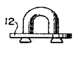
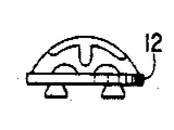
제1도는 서로 분리된 위치에 있어서 베이스 커플링 부재 및 캡 커플링부재를 나타내는 본 발명에 의한 화물 고정구의 사시도.1 is a perspective view of a cargo fastener according to the present invention showing the base coupling member and the cap coupling member in positions separated from each other.
제2도는 제1도에 나타낸 베이스 커플링부재의 상부 및 캡 커플링부재의 저부를 나타내는 평면도.FIG. 2 is a plan view showing the top of the base coupling member and the bottom of the cap coupling member shown in FIG.
제3도는 서로 결합된 위치에서 본 발명에 의한 화물 고정구의 수직 단면도.3 is a vertical sectional view of the cargo fastener according to the invention in a position coupled to each other.
제4a도는 운반체의 바닥표면에 용접되어 있는 베이스 커플링부재의 평면도.4A is a plan view of the base coupling member welded to the bottom surface of the carrier.
제4b도는 본 발명에 의한 베이스 커플링부재의 다른 실시예로서 그의 상단이 바닥의 표면과 같은 면으로서 운반체의 바닥에 파묻혀 있는 것을 나타낸 평면도 및 단면도.4b is a plan view and a sectional view of another embodiment of the base coupling member according to the present invention, the upper end of which is buried in the bottom of the carrier as the same surface as the bottom.
제5a도 내지 제5e도는 베이스 커플링부재와 함께 시용될 캡 커플링부재의 여러형태를 나타내는 단면도.5a to 5e are cross-sectional views showing various forms of cap coupling members to be used with the base coupling member.
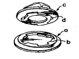
제6도 및 제7도는 종래 고정구의 개략도로서, 제6도는 서로 분리된 위치로에서 데크 소켓 및 캡부재를 나타내는 사시도.6 and 7 are schematic views of a conventional fixture, and Fig. 6 is a perspective view of the deck socket and cap member in a position separated from each other.
제7도는 서로 결합된 위치에서의 고정구의 단면도.7 is a cross-sectional view of the fixture in the position engaged with each other.
* 도면의 주요부분에 대한 부호의 설명* Explanation of symbols for main parts of the drawings
10 : 베이스커플링부재 12 : 캡커플링부재10: base coupling member 12: cap coupling member
14 : 소켓부 16 : 외측커플링돌기14
18 : 중앙각주 20 : 환상채널18: center footnote 20: annular channel
22 : 내측커플링돌기 24 : 플러그요소22: inner coupling protrusion 24: plug element
26 : 중앙요부 28 : 환상돌출부26: central main body 28: annular projection
30 : 외측커플링돌기 32 : 내측커플링돌기30: outer coupling protrusion 32: inner coupling protrusion
34, 36, 38, 40 : 경사진 아아치형 표면34, 36, 38, 40: inclined arched surface
42 : 아이치형홈 46 : 스토퍼핀42: Aichi groove 46: Stopper pin
48 : 배수노치48: drain notch
본 발명은 화물선, 자동차, 비행기 및 그와 유사한 운반체의 바닥에 화물을 고정하기 위해 사용되는 화물고정구(a cargo securing fitting)에 관한 것이다.The present invention relates to a cargo securing fitting used for securing cargo to the bottom of cargo ships, automobiles, airplanes and the like.
상세히 말하면, 본 발명은 운반체의 바닥에 고정 또는 용접되도록된 베이스 커플링부재와 베이스커플링부재에 연결되고 스태커 코운, 투위스트 로크 코운, 패드아이(padeye), 아이어링(eyering), 클로버리이프코운 및 운반체의 바닥위에 콘테이너, 플랜트, 운반기구 또는 그와 유사한 고형의 화물을 고정하거나 묶을 수 있는 것들중의 어느 하나를 갖춘 제거가능한 캡 커플링부재로 이루어지는 화물 고정구에 관한 것이며, 이에 의해 화물의 수송시 요동이나 붕괴되는 것으로부터 방지하도록 한 것이다.Specifically, the present invention relates to a base coupling member and a base coupling member adapted to be fixed or welded to the bottom of a carrier, and include a stacker cock, two twist lock cock, padeye, eyering, and cloverleaf. A cargo fastener consisting of a removable cap coupling member with any one of which can hold or bind a container, plant, conveyance device or similar solid cargo on the bottom of the corner and carrier. It is to prevent from shaking and collapsing during transportation.
즉 캡커플링부재는, 운반체에 의해 수송될 화물이 석탄, 광석, 곡물 또는 기타재료와 같은 포장되지 않은 낱짐이었을때 불도저의 작동이나 그랩(grab)의 운전을 위해 화물 공간 바닥이 매끄럽고 원활하도록 베이스 커플링 부재로부터 제거될 수 있다.That is, the cap coupling member is used to provide a smooth and smooth base for the cargo space floor for bulldozer operation or grab operation when the cargo to be transported by the carrier was an unwrapped bundle such as coal, ore, grain or other materials. It can be removed from the coupling member.
종래의 화물 고정구의 하나는 그위에 자 모양의 가이드부재가 제공된 베이스를 포함하는 소위 슬라이드 가이드 형이었다. 이 기구는 기구에 연결된 래싱수단이 가이드부재에 있어서 가이드부재의 개구로부터 해제된 방향으로 미끄러지기 쉬운 결점을 갖고 있다. 따라서, 이 공지의 기구는 수평의 요동함에 대해서만 스태커 코운으로서 단순히 사용될 수 있고 수직힘에 대한 고정구로서는 전혀 무가치하다.One of the conventional cargo fasteners was a so-called slide guide type comprising a base provided with a magnetic guide member thereon. This mechanism has the drawback that the lashing means connected to the mechanism is slippery in the direction in which the lashing means connected to the mechanism is released from the opening of the guide member. Thus, this known mechanism can simply be used as a stacker cone only for horizontal swings and is of no value as a fixture for vertical forces.
일본 특허공개공보 37781/1976호에는 다른 화물 고정구가 발표되어 있다. 이 고정구는 제6도 및 제7도에 나타낸 바와같이, 베이스부재의 에지주위에 상방 내측으로 돌출하는 플랜지(b)를 갖춘 베이스 커넥터부재(a), 및 하방외측으로 돌출하는 돌기(d)를 갖춘 인서어트 커넥터 부재(c)로 이루어진다.In Japanese Patent Laid-Open No. 37781/1976, another cargo fastener is disclosed. As shown in Figs. 6 and 7, the fastener has a base connector member (a) having a flange (b) projecting upwardly inwardly around the edge of the base member, and a projection (d) projecting downwardly outward. And an insert connector member (c) provided.
각각의 플랜지 및 돌기는 베이스 부재 및 인서어트 부재의 공통중심으로부터 약간 벗어난 곳에 위치된 꼭지점(apex)를 갖춘 절두 원추대의 부분에 대응한 비틀리고 경사진 계합면을 한정하도록 아아치형의 하부절단면을 지닌다.Each flange and protrusion has an arched lower cutting surface to define a twisted and inclined engagement surface corresponding to the portion of the truncated cone with an apex located slightly away from the common center of the base member and the insert member. .
이 형태의 베이스 커넥터부재는 그의 중앙영역에 비교적 큰 공간을 가진다.This type of base connector member has a relatively large space in its central area.
첫째로, 수직방향에서 그의 고정길이는 베이스 커넥터부재의 에지 둘레의 플랜지와 인서어트 커텍터부재의 돌기의 계합 영역이 비교적 작기 때문에 불충분하다.First, its fixed length in the vertical direction is insufficient because the engagement area of the flange around the edge of the base connector member and the projection of the insert connector member is relatively small.
둘째로, 베이스부재의 플랜지가 큰 중앙공간을 향해 내방으로 돌출된 사실때문에 플랜지가 화물조작시 불도저나 그랩에 의해 손상되기 쉽다. 이 형태의 화물 고정구의 다른 결점은 어렵고 비용이 많이 드는 기계적 가공이 플랜지 및 돌기에 편심적이고 비틀린 경사계합면을 형성하도록 요구되는데에 있다.Second, due to the fact that the flange of the base member protrudes inwardly toward the large central space, the flange is likely to be damaged by the bulldozer or grab during cargo operation. Another drawback of this type of cargo fastener is that difficult and costly mechanical machining is required to form eccentric and twisted mating surfaces on the flanges and projections.
따라서 본 발명의 주목적은 상기된 결점을 제거할 수 있는 채널형 화물 고정구를 제공하는 것이다.It is therefore a primary object of the present invention to provide a channelized cargo fastener capable of eliminating the above mentioned drawbacks.
본 발명의 다른 목적은 캡 커플링부재가 베이스 커플링부재로부터 분리되었을때 가해질 외부 충격력에 대해 견디도록 충분히 강한 베이스 커플링부재로 이루어지는 화물 고정구를 제공하는 것이다.Another object of the present invention is to provide a cargo fastener comprising a base coupling member that is sufficiently strong to withstand the external impact forces to be applied when the cap coupling member is separated from the base coupling member.
본 발명의 또 다른 목적은 서로 연결되어 있는 관계에서 베이스 커플링부재 및 캡 커플링부재사이에 항전단력(anti-shearing force) 및 항 장력(anti-tension force)을 효과적으로 증대시킬 수 있는 화물 고정구를 제공하는 것이다.Another object of the present invention is to provide a cargo fastener which can effectively increase the anti-shearing force and anti-tension force between the base coupling member and the cap coupling member in a connected relationship. To provide.
본 발명에 따르면, 그안에 원형의 소켓부를 갖추고 소켓부의 내부주위의 방사상 내측으로 돌출하는 복수개의 외측에서 거리를 둔 커플링 돌기(coupling lug) 및 중앙 각주(pillar)와 소켓부의 내주사이에 대체로 환상채널을 한정하도록 커플링 돌기와 같은 수준으로 소켓부의 상방으로 뻗어 있으며, 외부 커플링 돌기에 대해 직경상으로 대향된 관계로 중앙각주의 방사상 외방으로 돌출하는 복수개의 내측에서 거리를 둔 커플링 돌기와 함께 제공되는 원형의 중앙각주를 포함하는 베이스 커플링부재 ; 및 그의 하방으로 돌출하는 원형의 플러그 요소를 갖춘 제거가능한 캡 커플링부재로 이루어지며, 상기 플러그요소는 플러그 요소의 외주의 방사상 외방으로 돌출하는 복수개의 외측으로 거리를 둔 커플링 돌기 및 상기 환상채널에 수납하기 위한 환상돌기를 한정하도록 플러그 요소에 있어서 그의 하부면상에 형성된 원형의 중앙요부(凹部)를 포함하며, 상기 중앙요부는 외부커플링 돌기에 대해 직경상으로 대향된 관계로 중앙요부 주위의 방사상 내측으로 돌출하는 복수개의 내부에서 거리를 둔 커플링 돌기와 함께 제공되며, 캡 커플링 부재위의 상기 외부 및 내부 커플링 돌기들은 플러그요소의 환상돌출부가 베이스 커플링부재에 있어서 환상 채널내에 있을때 베이스 커플링부재에 관련되어 있는 캡 커플링부재를 돌림에 의해 각각 베이스 커플링부재의 내측 및 외측 커플링 돌기를 계합하도록 배치된다.According to the invention, there is a circular annulus therein and a plurality of outer spaced coupling lugs which project radially inwardly around the inner part of the socket part and a generally annular between the central pillar and the inner circumference of the socket part. It extends above the socket portion at the same level as the coupling protrusion to define the channel, and is provided with a plurality of inwardly spaced coupling protrusions projecting radially outwardly of the center foot in a diametrically opposed relationship to the outer coupling protrusion. A base coupling member including a circular central footnote; And a removable cap coupling member having a circular plug element protruding downward, the plug element comprising a plurality of outwardly spaced coupling projections and the annular channel protruding radially outward of the outer periphery of the plug element. A circular central recess formed on the lower surface of the plug element to define an annular projection for receiving therein, the central recess being radially opposed to the outer coupling protrusion, Provided with a plurality of internally spaced coupling protrusions projecting radially inwardly, wherein the outer and inner coupling protrusions on the cap coupling member have a base when the annular projection of the plug element is in the annular channel in the base coupling member. Base coupling respectively by turning the cap coupling member associated with the coupling member It is arranged to engage the material the inner and outer coupling protrusions.
베이스 커플링부재의 외측 커플링돌기는 대응하는 플러그 요소의 외속커플링돌기의 경사진 아아치형 표면을 계합하기 위한 내측으로 경사진 아아치형 표면과 함께 제공되며 동시에 중앙 각주의 각각의 내측 커플링 돌기는 중앙요부에 있어서 내측 커플링돌기의 대응하는 경사진 아아치형 표면을 계합하기 위한 외측으로 경사진 아아치형 표면과 함께 제공된다. 각 베이스 커플링부재 및 캡 커플링부재상의 외부 및 내부돌기의 경사진 아아치형 표면들은 중앙 각주의 수직축상에 그들의 꼭지점들을 가진 가상적 원추대들이다.The outer coupling protrusion of the base coupling member is provided with an inwardly inclined arched surface for engaging the inclined arched surface of the outer speed coupling protrusion of the corresponding plug element and at the same time each inner coupling protrusion of the center footnote. Is provided with an outwardly inclined arched surface for engaging the corresponding inclined arched surface of the inner coupling protrusion in the central recess. The inclined arched surfaces of the outer and inner protrusions on each base coupling member and cap coupling member are imaginary cones with their vertices on the vertical axis of the central footnote.
바람직하게는, 베이스 커플링부재는 2개의 인접한 외부 커플링돌기 근방에서 그안에 형성된 위치 홈과 함께 제공된다. 적어도 한개의 스토퍼 핀이 위치홈의 하나와 병합하도록 캡 커플링부재의 외측 커플링돌기에 대해 직경상으로 대향한 위치에서 캡 커플링부재의 하면에 설치되어 있고, 이에 따라 캡부재의 외측 및 내측 커플링돌기 등이 베이스부재의 내부 및 외부 커플링돌기들을 각각 계합한 위치에 대해 케이스 커플링부재에 관계된 캡 커플링부재의 회전을 제한시킨다.Preferably, the base coupling member is provided with a position groove formed therein near two adjacent outer coupling protrusions. At least one stopper pin is provided on the lower surface of the cap coupling member at a position diametrically opposed to the outer coupling protrusion of the cap coupling member so as to merge with one of the positioning grooves. Coupling projections and the like limit the rotation of the cap coupling member relative to the case coupling member with respect to the position where the inner and outer coupling projections of the base member are engaged respectively.
본 발명의 다른 목적과 특징들을 첨부도면에 따른 이하의 설명으로부터 명백해질 것이다.Other objects and features of the present invention will become apparent from the following description taken in conjunction with the accompanying drawings.
제1도에서 제3도를 참조하면, 본 발명에 의한 채널형 화물 고정구는 운반체의 바닥에 용접되거나 다른 방식으로 고정적으로 설치될 베이스 커플링부재(10) 및 베이스 커플링부재(10)에 제거가능하게 연결된 캡 커플링부재(12)로 이루어진다.Referring to Figures 1 to 3, the channel cargo fastener according to the present invention is removed from the
베이스 커플링부재(10)는 그의 상방으로 개구되는 원형의 소켓부(14)를 가지며 소켓부(14) 주위의 방사상 내측으로 돌출하는 복수개의 원주상으로 간격을 둔 외측 커플링돌기(16)와 함께 제공된다.The
중앙각주(18)는 소켓부(14)상에 형성되며 중앙각주(18) 및 소켓부(14) 주위사이에 환상채널(20)을 한정하도록 외측 커플링돌기(16)와 같은 레벨로 그의 상방으로 뻗어있다.The
복수개의 원주상으로 떨어진 내측 커플링돌기(22)는 외측커플링돌기(16)에 직경상으로 대향된 관계로 중앙각주(18)에 형성된다.A plurality of
캡 커플링부재(12)는 그의 하부면의 하단으로 돌출하는 플러그 요소(24)와 함께 제공된다.The
원형의 중앙요부(26)는 베이스 커플링부재(10)의 중앙각주(18)에 맞도록 그리고 중앙요부(26)와 베이스 커플링부재의 환상채널(20)내에 수납하기 위한 플러그요소(24) 주위사이에 환상돌출부(28)를 한정하도록 플러그요소(24)의 하면에 형성된다.The circular central recess 26 fits with the
복수개의 외측에서 간격을 둔 커플링돌기(30)는 베이스 커플링부재(10)의 외측 커플링돌기(16)와 병합하도록 플러그요소(24)에 형성된다.A plurality of spaced apart
플러그요소(24)는 중앙각주(18)의 내측커플링돌기(22)와 병합하도록 플러그 요소(24)의 외측커플링돌기(30)에 대해 직경상으로 대향된 관계로 중앙요부(26) 주위의 내측으로 돌출하는 복수개의 내측에서 간격을 둔 커플링돌기(32)와 함께 제공된다. 각각의 외측 커플링돌기(16)는 대응하는 캡 커플링부재(12)의 외측 커플링돌기(30)의 경사진 아아치형 표면(36)을 계합하는 내측으로 경사진 아아치형 표면(34)을 갖는다.The
각각의 내측 커플링돌기(22)는 대응하는 캡 커플링부재(12)의 내측 커플링돌기의 경사진 아아치형 표면(40)을 계합하는 외측으로 경사진 아아치형 표면(38)과 함께 제공된다.Each
커플링돌기의 경사진 아아치형 표면들(34, 36 및 38, 40)은 중앙각주(18)의 수직축상에 꼭지점을 가지는 가상적 원추대이다.The inclined arched surfaces 34, 36 and 38, 40 of the coupling protrusion are imaginary cones with vertices on the vertical axis of the
캡 커플링부재(12)는 플러그요소(24)의 환상돌출부(28)가 베이스 커플링부재의 환상채널(20)에 수납되도록 하기 위하여 베이스 커플링부재(10)의 인접한 커플링돌기들 사이의 공간과 일직선으로 플러그요소(24)의 각각의 커플링돌기(30 및 32)와 함께 베이스 커플링부재(10)상에 위치된다.The
다음, 캡 커플링부재(12)는 시계방향 또는 반시계 방향중 하나로 베이스 커플링부재(10)에 관련된 각주(18)의 축 주위로 회전된다.The
이 베이스 커플링부재(10)에 대한 캡 커플링부재의 회전은 외측 및 내측 커플링 돌기(30 및 32)가 각각 외측 및 내측 커플링돌기(16 및 22)를 계합하도록 하며, 이에 따라 경사진 아아치형 표면들(36, 34, 40, 38)이 서로 접촉하게 된다.Rotation of the cap coupling member relative to the
스토퍼수단은 외측 및 내측 커플링 돌기(30 및 32)가 대응하는 인접한 외부 및 내부 커플링 돌기와 각각 계합한 위치에서 베이스 커플링부재(10)에 대한 캡 커플링부재(12)의 회전을 제한하기 위해 제공된다.The stopper means restricts the rotation of the
스토퍼수단은 2개의 인접한 외측 커플링돌기(16) 및 각각의 아아치형 홈(42)와 병합하는 스토퍼 핀(46)에 인접하여 베이스 커플링부재(10)의 상부면에 형성된 2개의 직경상으로 대향의 아아치형 홈(42)을 포함한다.The stopper means have two diameters formed on the upper surface of the
이에 따라, 캡 커플링부재(12)의 회전은 아아치형 홈(42)의 최선단에 대해 스토퍼 핀(46)의 지주에 의해 정지된다.Accordingly, the rotation of the
2개의 직경상으로 대향한배수노치(48)들은 베이스 커플링부재(10)에 형성되어 있으며 소켓부에 괼 물의 제거가 용이하도록 아아치형 홈(42)을 가로질러 소켓부로부터 외측으로 뻗어있다.The two diametrically
배수노치(48)를 갖춘 베이스 커플링부재(10)는 제4a도에 나타낸 바와같이 그의 표면상에 운반체의 바닥(50)에 용접된다. 제4b도에 나타낸 경우에 있어, 베이스 커플링부재(10)는 운반체의 바닥(50)에 형성된 凹부(52)에 고정적으로 파묻혀 있으며, 베이스 커플링부재(10)에는 배수노치가 마련되어 있지 않다. 캡 커플링부재(12)는 운반체에 대해 컨테이너, 플랜드, 자동차 또는 그와 유사한 고형화물을 고정하거나 묶을 수 있는 수단이다.
제1도, 제3도 및 제5a도는 그의 상단으로부터 상방으로 뻗어있는 스태커코운과 함께 제공된 캡 커플링부재(12)를 나타낸다. 제5b도는 투위스트 로크 코운을 갖춘 캡부재, 제5c도는 패드 아이를 갖춘 캡부재, 제5d도는 아이어링을 갖춘 캡부재, 제5e도는 클로버리이프 코운을 갖춘 캡부재를 나타낸다.1, 3 and 5a show a
상기한 바와같이, 운반체의 화물스페이스에 고형화물을 적재하도록 요망되었을때, 각 캡 커플링부재(12)는 상술한 상태로 화물스페이스의 바닥에 고정된 베이스 커플링부재(10)에 연결된다. 본 발명에 따르면, 캡부재의 외부 및 내부 커플링돌기와 베이스부재의 외부 및 내부 커플링돌기의 계합은 화물운반체에 대해 고형화물을 고정하거나 묶음에 있어서 보다 높은 인장력이 캡 커플링부재에 가하잴 수 있도록 한다.As described above, when it is desired to load solid cargo in the cargo space of the vehicle, each
불도저나 그랩을 사용하는 석탄, 광석, 곡물 또는 기차 낱개로된 재료와 같은 낱짐을 갖춘 화물을적재하기에 앞서 역상으로 베이스 커플링부재(10)로부터 캡 커플링부재(12)를 제거하도록 요망된다.It is desired to remove the
따라서 베이스 커플링부재(10)는 노출된 베이스 커플링부재가 낱짐의 부하 또는 무부하작업 사이에 불도저나 그랩에 대항할 수 있도록 하기 위하여 그로부터 캡부재(12)를 분리함에 의해 적하장소에 노출된다.Thus, the
충격력이 불도저나 그랩에 의해 베이스 커플링부재에 가해졌을때, 그 힘은 중앙각주는 물론 소켓부 주위의 베이스 부재의 에지에 의해 받아들어질 것이다.When an impact force is applied to the base coupling member by a bulldozer or grab, the force will be received by the edge of the base member around the socket portion as well as the center foot.
중앙각주 및 베이스부재의 에지에 대한 충격력의 동시적 적용은 베이스 커플링부재의 커플링돌기의 어떠한 손상도 피할 수 있도록 한다.Simultaneous application of the impact force on the edges of the center foot and the base member allows any damage of the coupling projection of the base coupling member to be avoided.
즉, 중앙각주는 베이스부재상의 하나 또는 그 이상의 외부돌기를 손상시킬 수 있는, 베이스 커플링부재의 에지에 국부적으로 가해지는 충격력을 방지하도록 보조한다.That is, the center footnote assists in preventing the impact force applied locally to the edge of the base coupling member, which may damage one or more outer projections on the base member.
비록 본 발명은 첨부도면에 따른 1실시예에 따라 기술되었으나, 본 발명의 정신과 관점으로부터 벗어남이 없이도 본 발명의 원리에 근간하여 본 기술에 숙련된 사람들에 의해서 많은 수정과 변경이 가해질 수 있음을 알아야 할것이다.Although the invention has been described in accordance with one embodiment according to the accompanying drawings, it should be understood that many modifications and changes can be made by those skilled in the art based on the principles of the invention without departing from the spirit and viewpoint of the invention. something to do.
Claims (3)
Applications Claiming Priority (2)
| Application Number | Priority Date | Filing Date | Title |
|---|---|---|---|
| JP56042125A JPS57155190A (en) | 1981-03-21 | 1981-03-21 | Metal fitting for channel type lashing |
| JP???56-42125 | 1981-03-21 |
Publications (2)
| Publication Number | Publication Date |
|---|---|
| KR830008900A KR830008900A (en) | 1983-12-16 |
| KR880001985B1 true KR880001985B1 (en) | 1988-10-10 |
Family
ID=12627214
Family Applications (1)
| Application Number | Title | Priority Date | Filing Date |
|---|---|---|---|
| KR8201195A KR880001985B1 (en) | 1981-03-21 | 1982-03-20 | Gargo securing fitting |
Country Status (7)
| Country | Link |
|---|---|
| US (1) | US4400856A (en) |
| EP (1) | EP0061085B1 (en) |
| JP (1) | JPS57155190A (en) |
| KR (1) | KR880001985B1 (en) |
| DE (1) | DE3262268D1 (en) |
| ES (1) | ES272539Y (en) |
| NO (1) | NO820910L (en) |
Cited By (2)
| Publication number | Priority date | Publication date | Assignee | Title |
|---|---|---|---|---|
| KR200448690Y1 (en) * | 2008-01-25 | 2010-05-07 | 현대중공업 주식회사 | Cone of contianer |
| KR101626789B1 (en) * | 2015-10-21 | 2016-06-02 | 대광기업 주식회사 | Lashing product |
Families Citing this family (65)
| Publication number | Priority date | Publication date | Assignee | Title |
|---|---|---|---|---|
| GB2119720A (en) * | 1982-05-04 | 1983-11-23 | Stainless W S Fixings | Removable boat fitting |
| US4527760A (en) * | 1983-06-29 | 1985-07-09 | Super Glue Corporation | Adjustable clip system |
| JPS6188895U (en) * | 1984-11-17 | 1986-06-10 | ||
| US4645392A (en) * | 1985-04-22 | 1987-02-24 | Taiyo Seiki Iron Works Co., Ltd. | Deck fitting |
| US4599768A (en) * | 1985-05-13 | 1986-07-15 | Illinois Tool Works Inc. | Spin welded fastening assembly |
| US4779516A (en) * | 1985-09-16 | 1988-10-25 | General Motors Corporation | Cam and lock vacuum booster mount with locking arm |
| CH667779A5 (en) * | 1985-10-04 | 1988-11-15 | Ueli Eser | CONNECTION BETWEEN A PEDAL FOR A BICYCLE AND A SHOE. |
| GB2181178A (en) * | 1985-10-04 | 1987-04-15 | Gen Motors France | A method of attaching a brake booster to a vehicle |
| DE3539800A1 (en) * | 1985-11-09 | 1987-05-14 | Gewerk Eisenhuette Westfalia | JOINT CONNECTION FOR THE GAP COVER ON THE BREAKAGE PLATE AND ON THE HANGING CAP OF A SHIELD EXTENSION RACK |
| US4630982A (en) * | 1985-11-27 | 1986-12-23 | The Boeing Company | Cargo tie-down system |
| US4722654A (en) * | 1986-06-30 | 1988-02-02 | Rca Corporation | Article transfer system |
| US4958875A (en) * | 1988-11-14 | 1990-09-25 | Zamzow Larry A | Truck pocket rail attachment |
| US5107573A (en) * | 1991-01-16 | 1992-04-28 | Ning Zhang | Rotating connector |
| FR2675219A1 (en) * | 1991-04-11 | 1992-10-16 | Moulinex Sa | FIXING DEVICE FOR RETAINING IN A POSITION DETERMINED A FIRST PIECE ON A SECOND PART. |
| US5290195A (en) * | 1991-10-17 | 1994-03-01 | Prickett Timothy B | Releasable anchor plug for watersport boards |
| US5199916A (en) * | 1991-10-17 | 1993-04-06 | Prickett Timothy B | Releasable anchor plug |
| AUPM754294A0 (en) * | 1994-08-18 | 1994-09-08 | Nyholm, Ture | Automatic twistlock |
| AU687217B2 (en) * | 1994-08-18 | 1998-02-19 | Ture Nyholm | Automatic twistlock |
| US5685642A (en) * | 1994-09-23 | 1997-11-11 | Honeywell Inc. | Mounting for a bimetal coil thermometer and having an integral feature assisting calibration |
| US5607251A (en) * | 1996-04-03 | 1997-03-04 | The Stanley Works | Quick coupler assembly for hanging attachment |
| USD380664S (en) * | 1996-04-18 | 1997-07-08 | Lowrance Electronics, Inc. | Buoyant support |
| US5956822A (en) * | 1996-06-12 | 1999-09-28 | Knecht Filterwerke Gmbh | Snap-lock connection for two parts which can rotate in relation to each other |
| DE29614444U1 (en) * | 1996-08-20 | 1997-12-18 | Rumpp Gerhard | Coupling arrangement for a vehicle |
| US5887376A (en) * | 1997-01-09 | 1999-03-30 | Lowrance Electronics, Inc. | Buoyant transducer assembly for assisting an angler |
| US5791809A (en) * | 1997-04-24 | 1998-08-11 | Harnischfeger Technologies, Inc. | Dragline with improved pin-retaining structure |
| US6030159A (en) * | 1997-07-29 | 2000-02-29 | Aar Corp. | Multipurpose cargo tie down system |
| US6382488B1 (en) * | 1999-12-14 | 2002-05-07 | Dennis Hancock | Multiple use base holder system |
| US6393672B1 (en) * | 2000-09-19 | 2002-05-28 | Joseph Anscher | D-ring assembly |
| US6490766B1 (en) | 2000-09-25 | 2002-12-10 | Peck & Hale Llc | Coupling device including automatic latching lock |
| TW486949U (en) * | 2001-05-16 | 2002-05-11 | L & Amp F Plastics Co Ltd | Assembly of placement plate |
| US6929223B2 (en) * | 2002-12-17 | 2005-08-16 | Stearns Inc. | Air cushioned grippers for article holders |
| US7066366B2 (en) * | 2003-06-16 | 2006-06-27 | Stearns Inc. | Long gun carrying system for all terrain vehicles |
| US20050045681A1 (en) * | 2003-08-25 | 2005-03-03 | Hancock Dennis H. | All terrain vehicle portable radio mount |
| TWM273242U (en) * | 2005-03-16 | 2005-08-21 | Button Int Co Ltd | Rotational safety buckle |
| JP4668107B2 (en) * | 2006-03-29 | 2011-04-13 | 株式会社アルファ | Steering lock device |
| FR2905643B1 (en) * | 2006-09-11 | 2008-11-07 | Renault Sas | ARRANGEMENT FOR FASTENING HITCH RINGS IN A VEHICLE |
| JP2008095855A (en) * | 2006-10-12 | 2008-04-24 | Pioneer Electronic Corp | Fixing structure |
| US20080119339A1 (en) * | 2006-11-16 | 2008-05-22 | Oliver Michael J | Quick change end of arm tool attachment |
| US7958967B2 (en) * | 2007-01-12 | 2011-06-14 | James Lambdin | Mud sill |
| KR101573418B1 (en) * | 2007-09-07 | 2015-12-01 | 헌터 더글라스 인더스트리즈 비.브이. | Universal connector |
| US20090139464A1 (en) * | 2007-12-04 | 2009-06-04 | Rose America Corporation | Animal Restraint with Snap Hook and Buckle |
| US20100230209A1 (en) * | 2009-03-16 | 2010-09-16 | Tim Hughes | Quick disconnect ladder assembly |
| US8141829B2 (en) * | 2009-06-12 | 2012-03-27 | Physical Systems, Inc. | Low profile adhesive mounted fixture button |
| US20110290171A1 (en) * | 2010-05-27 | 2011-12-01 | Christopher Allen Brick | Assembly for attaching a flag to an object |
| US8544805B2 (en) * | 2010-05-28 | 2013-10-01 | VirGiaN, LLC | Mounting system for removably securing an object to a surface |
| US8568070B2 (en) * | 2010-11-01 | 2013-10-29 | Peck & Hale, L.L.C. | Cargo lashing fitting |
| US8475073B1 (en) | 2011-03-08 | 2013-07-02 | Structural Plastics, Inc. | Pivot connector for modular platform assemblies |
| GB201214341D0 (en) * | 2012-08-10 | 2012-09-26 | Snap Alloy Ltd | Connector system |
| US9027892B2 (en) * | 2013-05-14 | 2015-05-12 | Rosemount Aerospace Inc. | Rotating electronic display mount |
| US9340142B1 (en) * | 2013-06-11 | 2016-05-17 | Peck & Hale, L.L.C. | Cover for cargo lashing fitting |
| CN203604354U (en) * | 2013-10-25 | 2014-05-21 | 明达实业(厦门)有限公司 | Connection buckle structure |
| US9273707B2 (en) * | 2014-01-07 | 2016-03-01 | Seong Hwan Lee | Female-male combination type ornament |
| CN106455763B (en) | 2014-05-13 | 2021-02-05 | Wrdt有限责任公司 | Attachment device |
| US10182609B2 (en) * | 2014-07-28 | 2019-01-22 | Speedplay, Inc. | Aperture cover for bicycle cleat assembly |
| US9756930B2 (en) * | 2015-04-28 | 2017-09-12 | Axon Enterprise, Inc. | Methods and apparatus for a low-profile coupler |
| US10118674B1 (en) | 2016-03-10 | 2018-11-06 | Peck & Hale, L.L.C. | Cargo lashing fitting |
| CA2970460C (en) * | 2016-06-20 | 2023-09-05 | Dion Del Monte | Sports training apparatus |
| DE102017118251A1 (en) | 2017-08-10 | 2019-02-14 | Airbus Operations Gmbh | Coupling element and coupling system and method for coupling two modules and aircraft |
| US11052813B1 (en) | 2018-02-21 | 2021-07-06 | Peck & Hale, L.L.C. | Cargo lashing fitting |
| US11046233B1 (en) | 2018-12-18 | 2021-06-29 | Peck & Hale, L.L.C. | Cargo lashing fitting |
| US10813417B2 (en) * | 2019-01-25 | 2020-10-27 | Love Your Melon Inc. | Snap fastener receiver techniques |
| CA3048519A1 (en) * | 2019-07-02 | 2021-01-02 | Rubber Recon Inc. | Strap connection systems, quick connectors, and related systems and methods |
| EP3919762B1 (en) * | 2020-06-03 | 2023-11-22 | Illinois Tool Works, Inc. | Fastener |
| US11766144B2 (en) * | 2020-06-12 | 2023-09-26 | Christopher Levi Kraus | Container stability mounting apparatus |
| JP2023155783A (en) * | 2022-04-11 | 2023-10-23 | 朝日インテック株式会社 | Muscle training apparatus |
Family Cites Families (9)
| Publication number | Priority date | Publication date | Assignee | Title |
|---|---|---|---|---|
| US279568A (en) * | 1883-06-19 | Separable button | ||
| US2812974A (en) * | 1955-09-22 | 1957-11-12 | Hubert J Mchugh | Removable transport-container locking mechanism |
| US3367000A (en) * | 1965-10-23 | 1968-02-06 | Boeing Co | Detachable fastening device |
| GB1191985A (en) * | 1968-06-04 | 1970-05-13 | Backtemans Patenter Ab | Improvements in means for Securing Deck Cargoes on Ships |
| US3860209A (en) * | 1971-09-14 | 1975-01-14 | Peck & Hale | Deck socket assembly |
| US3811157A (en) * | 1972-10-26 | 1974-05-21 | Dzus Fastener Co | Tamper-proof fastener |
| DE2431247A1 (en) * | 1974-06-28 | 1976-01-15 | Peck & Hale | Vehicle container load fixture arrangement - uses retention bolt locating in lengthways hole of fitment |
| US4125339A (en) * | 1977-06-29 | 1978-11-14 | Pittinger Sr Charles B | Releasably interlocked, assymmetrical, lugged flange joint with fixed relative orientation |
| US4129395A (en) * | 1977-07-05 | 1978-12-12 | Theurer Atlantic Incorporated | Container lock assembly |
-
1981
- 1981-03-21 JP JP56042125A patent/JPS57155190A/en active Granted
-
1982
- 1982-03-11 US US06/357,088 patent/US4400856A/en not_active Expired - Fee Related
- 1982-03-12 DE DE8282101984T patent/DE3262268D1/en not_active Expired
- 1982-03-12 EP EP82101984A patent/EP0061085B1/en not_active Expired
- 1982-03-18 ES ES1982272539U patent/ES272539Y/en not_active Expired
- 1982-03-19 NO NO820910A patent/NO820910L/en unknown
- 1982-03-20 KR KR8201195A patent/KR880001985B1/en active
Cited By (2)
| Publication number | Priority date | Publication date | Assignee | Title |
|---|---|---|---|---|
| KR200448690Y1 (en) * | 2008-01-25 | 2010-05-07 | 현대중공업 주식회사 | Cone of contianer |
| KR101626789B1 (en) * | 2015-10-21 | 2016-06-02 | 대광기업 주식회사 | Lashing product |
Also Published As
| Publication number | Publication date |
|---|---|
| KR830008900A (en) | 1983-12-16 |
| JPS57155190A (en) | 1982-09-25 |
| EP0061085A1 (en) | 1982-09-29 |
| ES272539U (en) | 1984-03-01 |
| EP0061085B1 (en) | 1985-02-13 |
| NO820910L (en) | 1982-09-22 |
| US4400856A (en) | 1983-08-30 |
| ES272539Y (en) | 1984-10-01 |
| JPS6220076B2 (en) | 1987-05-02 |
| DE3262268D1 (en) | 1985-03-28 |
Similar Documents
| Publication | Publication Date | Title |
|---|---|---|
| KR880001985B1 (en) | Gargo securing fitting | |
| US4256240A (en) | Container closure | |
| KR920002213Y1 (en) | Container-fastening lock apparatus | |
| US4703857A (en) | Thin-walled stackable container lid | |
| US4485932A (en) | Child resistant package | |
| EP0423935B1 (en) | Child resistant closure | |
| US4378895A (en) | Container-closure arrangement | |
| US3046853A (en) | Manhole closure | |
| US4465205A (en) | Fragile opening means for a container lid | |
| US20130087573A1 (en) | Container | |
| US3983725A (en) | Padlock case | |
| US7487879B2 (en) | Fuel filler cap | |
| EP0809034B1 (en) | Bellows-type cover with integrated clamping member | |
| US5704659A (en) | Valve adapter locking system | |
| US2098087A (en) | Pipe thread protector | |
| JP4596821B2 (en) | Oil filler cap | |
| US3876069A (en) | Method and apparatus for projecting tire beads | |
| JPS6320637Y2 (en) | ||
| US3392871A (en) | Container with opening means | |
| KR100654419B1 (en) | Taper manhole | |
| US1208240A (en) | Receptacle. | |
| JPS5938532Y2 (en) | Manhole with fastening mechanism | |
| EP0696701B1 (en) | A sealing ring device | |
| JPS63110161A (en) | Cap for fuel tank | |
| KR100406149B1 (en) | Device for preventing from inclining to one side |