KR880001360B1 - Radio frequency field coil for nmr - Google Patents
Radio frequency field coil for nmr Download PDFInfo
- Publication number
- KR880001360B1 KR880001360B1 KR1019840006840A KR840006840A KR880001360B1 KR 880001360 B1 KR880001360 B1 KR 880001360B1 KR 1019840006840 A KR1019840006840 A KR 1019840006840A KR 840006840 A KR840006840 A KR 840006840A KR 880001360 B1 KR880001360 B1 KR 880001360B1
- Authority
- KR
- South Korea
- Prior art keywords
- coil
- nmr
- segments
- conductive
- elements
- Prior art date
Links
Images


Classifications
-
- G—PHYSICS
- G01—MEASURING; TESTING
- G01R—MEASURING ELECTRIC VARIABLES; MEASURING MAGNETIC VARIABLES
- G01R33/00—Arrangements or instruments for measuring magnetic variables
- G01R33/20—Arrangements or instruments for measuring magnetic variables involving magnetic resonance
- G01R33/28—Details of apparatus provided for in groups G01R33/44 - G01R33/64
- G01R33/32—Excitation or detection systems, e.g. using radio frequency signals
- G01R33/34—Constructional details, e.g. resonators, specially adapted to MR
- G01R33/34046—Volume type coils, e.g. bird-cage coils; Quadrature bird-cage coils; Circularly polarised coils
-
- G—PHYSICS
- G01—MEASURING; TESTING
- G01R—MEASURING ELECTRIC VARIABLES; MEASURING MAGNETIC VARIABLES
- G01R33/00—Arrangements or instruments for measuring magnetic variables
- G01R33/20—Arrangements or instruments for measuring magnetic variables involving magnetic resonance
- G01R33/28—Details of apparatus provided for in groups G01R33/44 - G01R33/64
- G01R33/32—Excitation or detection systems, e.g. using radio frequency signals
- G01R33/34—Constructional details, e.g. resonators, specially adapted to MR
- G01R33/34007—Manufacture of RF coils, e.g. using printed circuit board technology; additional hardware for providing mechanical support to the RF coil assembly or to part thereof, e.g. a support for moving the coil assembly relative to the remainder of the MR system
Abstract
Description
제1a도 내지 제1d도는 종래의 핵자기 공명(NMR)장치의 여러가지 RF 코일(이하 NMR RF 코일이라 칭함)을 도시한 것인데,1A to 1D show various RF coils (hereinafter referred to as NMR RF coils) of a conventional nuclear magnetic resonance (NMR) device.
제1a도는 피검체 전부를 검사할 수 있는 병렬 연결된 2권수를 가진 NMR RF 코일의 개략도.1A is a schematic diagram of an NMR RF coil with two volumes connected in parallel capable of inspecting all subjects.
제1b도는 제1도의 코일을 원통상으로 한 것을 도시한 도면.FIG. 1B is a view showing a cylindrical cylinder of FIG.
제1c도는 예를 들면 머리 부분의 NMR 연구에 쓰일수 있는 직렬 연결된 2권수를 가진 NMR RF 코일의 개략도.Figure 1c is a schematic diagram of an NMR RF coil with two volumes connected in series, for example, which can be used for NMR studies of the head.
제1d도는 다른 종류의 종래의 NMR RF 코일을 도시한 것.1d illustrates another type of conventional NMR RF coil.
제2a도는 본 발명에 따라 만든 코일의 기본 소자를 이루는 단권수를 가진 새들(saddle)형 코일의 개략도.Figure 2a is a schematic diagram of a saddle-shaped coil with a single turn forming the basic element of the coil made in accordance with the present invention.
제2b도는 본 발명의 NMR RF 코일의 개략도.2b is a schematic diagram of an NMR RF coil of the present invention;
제3a도는 본 발명의 NMR RF 코일의 등가럼프(lump)소자의 회로도.3A is a circuit diagram of an equivalent lump element of the NMR RF coil of the present invention.
제3b도는 제3a도의 회로를 구성하는 다수의 반복회로 유니트 중의 하나를 도시한 것.FIG. 3B shows one of a plurality of repeating circuit units constituting the circuit of FIG. 3A.
제4도는 두 점에서 동작될 수 있는 본 발명의 NMR RF 코일의 일실시예를 도시한 것.4 illustrates one embodiment of an NMR RF coil of the present invention that can be operated at two points.
제5a도는 도전성 루우프 소자에서 전류 방향을 도시한 본 발명의 NMR RF 코일의 평면도.5A is a plan view of an NMR RF coil of the present invention showing the current direction in a conductive loop element.
제5b도는 제5a도에 도시된 수직 세그먼트에서의 정현파 적인 전류 분포도.FIG. 5b is a sinusoidal current distribution in the vertical segment shown in FIG.
제5c도는 제5a도에 도시된 코일의 도전성 루우프 소자에서의 전류 분포도.FIG. 5C is a current distribution diagram of the conductive loop element of the coil shown in FIG. 5A.
제5d도는 윈도우가 형성되고, 변형된 루우프 소자를 가진 본 발명의 NMR RF 코일을 도시한 것.5d illustrates an NMR RF coil of the present invention having a window formed and a modified loop element.
제5e도는 몇개가 제거된 세그먼트들을 가진 제5b도의 코일의 수직 세그먼트에서의 전류 분포도.FIG. 5e is a current distribution diagram in the vertical segment of the coil of FIG. 5b with some removed segments.
제6a도 내지 제6c도는 각각 제5a도 내지 제5c도와 유사한 도면.6a to 6c are views similar to FIGS. 5a to 5c, respectively.
제7a도 및 제7b도는 본 발명의 NMR RF 코일의 양호한 실시예를 조립하는 데 편리한 도전성 패턴을 보여준것.7a and 7b show a convenient conductive pattern for assembling a preferred embodiment of the NMR RF coil of the present invention.
제8a도는 각 도체속에 형성된 가변 커패시터를 가진 다수의 수직 도체로 구성한 본 발명의 NMR RF 코일의 일실시예를 도시한 것.FIG. 8A shows one embodiment of the NMR RF coil of the present invention consisting of a plurality of vertical conductors with variable capacitors formed in each conductor.
제8b도는 제8a도에 도시된 실시예에 사용될 수 있는 가변 커패시터의 횡단면도.FIG. 8B is a cross sectional view of a variable capacitor that may be used in the embodiment shown in FIG. 8A.
제9a도는 각 단부에 고정 커패시터를 가진 다수의 수직 도체로 구성된 본 발명의 코일의 다른 실시예.Figure 9a illustrates another embodiment of the coil of the present invention consisting of a plurality of vertical conductors with fixed capacitors at each end.
제9b도는 제9a도에 도시된 코일 실시예에 사용되는 커패시터 구조의 상세도.FIG. 9B is a detailed view of the capacitor structure used in the coil embodiment shown in FIG. 9A.
제10도는 유전체를 포함한 망원결 경통 형태의 외측면에 판처럼 구성되고 짧은 평형 도선들을 가진 본 발명의 NMR RF 코일의 또 다른 실시예.FIG. 10 is another embodiment of the NMR RF coil of the present invention constructed as a plate and having short balanced conductors on the outer surface of a telephoto barrel type including a dielectric.
제11도는 유전체를 포함한 원통형의 외측면을 가진 나란하게 격리된 도선들로 구성된 본 발명의 NMR RF 코일의 또 하나의 실시예.FIG. 11 is another embodiment of the NMR RF coil of the present invention consisting of side-by-side isolated conductors having a cylindrical outer surface including a dielectric.
제12도는 본 발명의 NMR RF 코일에서 임피던스 정합에 쓰이는 다수의 고정 커패시터가 형성된 수직 도선중 선택된 도선의 상세도이다.12 is a detailed view of selected conductors among vertical conductors in which a plurality of fixed capacitors are used for impedance matching in the NMR RF coil of the present invention.
* 도면의 주요부분에 대한 부호의 설명* Explanation of symbols for main parts of the drawings
1,3 : 평행한 단권선 5 : 구리판1,3: parallel single winding 5: copper plate
7,9 : 접점 8 : 동조 커패시터7,9: contact point 8: tuning capacitor
11 : 원통 21a,22a : 도전성 세그먼트11: cylinder 21a, 22a: conductive segment
27a, 28a : 단자 33,34 : 커패시터 소자27a, 28a:
71,73 : 루우프 소자 85 : 구리 패드71,73: loop element 85: copper pad
101 : 수직도체 104 : 가변 커패시터101: vertical conductor 104: variable capacitor
130 : 수직 도체 155-160 : 단자들130: vertical conductor 155-160: terminals
본 발명은 핵자기 공명(NMR) 장치에 관한 것으로, 특히 무선 주파수(RF)를 송수신할 수 있는 NMR RF코일에 관한 것이다.The present invention relates to a nuclear magnetic resonance (NMR) device, and more particularly to an NMR RF coil capable of transmitting and receiving radio frequency (RF).
과거에 NMR 현상은 실험실에서 유기 분자의 분자 구조를 연구하는데 구조화학자들에 의해 사용되었다. 전형적으로 이런 목적을 위해 NMR 분광계들이 검사될 물질의 작은 샘플을 수용할 수 있도록 설게되었다. 최근에는, NMR 은 예를 들면 살아있는 인간 조직의 해부학적 연상을 얻는데 쓰이도록 발전하였다. 핵자기 스핀과 관련된 변수(전형적으로 조직내의 물과 관련된 수소의 양성자)를 표시하는 영상은 검사된 부분의 조기의 건강 상태를 결정하는 의학적 진단에 쓰일 수 있다. NMR 기술은 처음에 생체 기관의 화학적 과정을 연구하는데 쓰이는 한 도구로서 사용되었다. 그것은 또한 인, 탄소와 같은 원소의 생체내에서 분광 연구에 쓰일 수 있게 확장되었다. 영상을 발생하고 인간 조직의 분광 연구에 NMR을 사용함에 따라 자석, 그래디언트 및 RF 코일과 같은 특별히 설게된 시스템 부품들의 사용이 불가피하게 되었다.In the past, NMR phenomena have been used by structural chemists in the laboratory to study the molecular structure of organic molecules. Typically for this purpose, NMR spectrometers have been designed to accommodate small samples of the material to be inspected. Recently, NMR has been developed to be used, for example, to obtain anatomical associations of living human tissue. Images displaying variables related to nuclear magnetic spin (typically the protons of hydrogen associated with water in tissues) can be used for medical diagnosis to determine the premature health status of the examined area. NMR technology was initially used as a tool for studying chemical processes in living organs. It has also been extended to be used for spectroscopic studies in vivo of elements such as phosphorus and carbon. The use of specially designed system components, such as magnets, gradients and RF coils, has been inevitable, as imaging and the use of NMR for spectroscopic studies of human tissue.
본 발명의 배경에 대해 말하면, 핵자기 공명 현상은 홀수의 양성자들 또는 중성자들을 가진 원자핵에서 일어난다. 양성자 및 중성자의 스핀에 의해, 각각의 그러한 핵들은 자기 모멘트, 즉, 그러한 핵들을 포함한 샘플이 군질 정지 자계내에 위차될때 보다 많은 수의 핵자기 모멘트가, 자계방향에 따라 순수거시 자화 M을 발생하도록 정열된다. 자계 B0의 영향으로 인가 자계에 따르는 또한 핵의 특성에 따르는 주파수에서 자계축에 관해 그 자기 모멘트는 세차운동을 한다. 그러한 각 세차운동 w은 라몬어 주파수로 불리워지며, w=rB으로 정의된다. 여기에서 r은 자기회전비율로서 각 NMR 동위원소에 대해 상수이고, B는 핵 스핀에 작용하는 자계로서 상기 균질 자계 B0에 다른 자계를 합한 자계이다. 그러므로 샘플이 위치되는 자계 강도에 따라 공명주파수가 다르다는 것은 명백하다.In the context of the present invention, nuclear magnetic resonance phenomena occur in an atomic nucleus with an odd number of protons or neutrons. By spin of protons and neutrons, each of these nuclei causes the magnetic moment, i.e., a greater number of nuclear magnetic moments, to generate pure macromagnetism M along the direction of the magnetic field when a sample containing such nuclei deviates within the group static magnetic field. Are aligned. Under the influence of the magnetic field B 0 , the magnetic moment is precessed about the magnetic axis at frequencies according to the applied magnetic field and also the characteristics of the nucleus. Each such precession w is called the Ramon frequency and is defined by w = rB. Where r is the magnetic rotation rate and is constant for each NMR isotope, and B is the magnetic field acting on the nuclear spin, the magnetic field obtained by adding the other magnetic field to the homogeneous magnetic field B 0 . Therefore, it is obvious that the resonant frequency is different depending on the magnetic field strength where the sample is located.
자계 B0에 따라 정상적으로 방향진 자화 M의 배향은 라모어 주파수로 또는 그 근처 주파수로 진동하는 자계를 가함으로 섭동될 수 있다. 전형적으로, 그러한 B1자계는 무선 주파수 송신 장치에 연결된 코일을 통해 무선 주파수 펄스로 자화 M의 방향에 수직으로 가해진다. 자화 M는 B1자계방향에 대해 회전한다. NMR에서, 일반적으로 RF 펄스가 충분한 크기와 지속을 갖고 B0자계 방향에 수직인 평면으로 자화 M을 회전하도록 인가되어야만 한다. 이 평면을 보통 수평면으로 부른다. RF 여기가 중지되면, 수평면으로 회전된 핵 모멘트는 물리적 과정의 한 변형으로 B0자계와 재정렬되기 시작한다. 이 재정렬 과정에서, 핵 모멘트는 NMR 신호라하는 무선 주파수 신호를 방사한다. 이 NMR 신호들은 자계 및, 핵이 처한 특별한 화학적 환경의 한 특성이다. 핵으로부터 방사된 그러한 신호를 수신하기 위해 동일 또는 제2 RF 코일이 사용된다. NMR 영상화응용에 있어서, NMR 신호들이 공간정보를 NMR 신호로 부호화 하도록 쓰이는 자계 그래디언트의 존재하에 관측된다. 이 정보가 후에 본 분야의 공지의 방식으로 피검체의 영상을 재구성하는데 쓰인다.The orientation of the normally directed magnetization M in accordance with the magnetic field B 0 can be perturbed by applying a magnetic field oscillating at or near the lamore frequency. Typically, such B 1 magnetic field is applied perpendicularly to the direction of magnetization M with radio frequency pulses through a coil connected to the radio frequency transmitter. The magnetization M rotates about the B 1 magnetic field direction. In NMR, RF pulses generally have to be applied to rotate magnetization M in a plane of sufficient magnitude and duration and perpendicular to the B 0 magnetic field direction. This plane is usually called the horizontal plane. When the RF excitation is stopped, the nuclear moment rotated in the horizontal plane begins to realign with the B 0 magnetic field as a variation of the physical process. In this realignment process, the nuclear moment radiates radio frequency signals called NMR signals. These NMR signals are a characteristic of the magnetic field and the special chemical environment in which the nucleus is located. The same or second RF coil is used to receive such a signal radiated from the nucleus. In NMR imaging applications, NMR signals are observed in the presence of magnetic field gradients used to encode spatial information into NMR signals. This information is later used to reconstruct the image of the subject in a manner known in the art.
인체 전부의 NMR 연구를 하는데는 균질자계 B0의 강도를 증가시키는 것이 유리하다고 알려졌다. 이렇게 하기 위해 NMR 신호의 신호대 잡음비를 양성자 연상화의 경우에 개선해야할 필요성이 있다. 분광학에서, 그러나, 연구될 몇가지 화학 성분(예를 들면, 인과 탄소등)은 인체내에서 비교적 소수이므로 사용 가능한 신호를 검출하기 위해서 고 자계가 필요하다. 라모어 주파수에 관한 식으로부터 명백하듯이, 자계 B를 증가하면 그에 따라 w에서의 증가를 수반하고 따라서 송신기 및 수신기 코일의 공진 주파수에서의 증가를 가져온다. 이것은 인체를 수용할 수 있는 큰 RF 코일의 설계를 복잡하게 한다.Increasing the strength of the homogeneous field B 0 is known to be beneficial for NMR studies of the entire human body. To do this, there is a need to improve the signal-to-noise ratio of the NMR signal in the case of proton association. In spectroscopy, however, some of the chemical components to be studied (eg phosphorus and carbon) are relatively few in the human body and require a high magnetic field to detect usable signals. As is apparent from the equation for lamore frequency, increasing magnetic field B thus involves an increase in w and thus an increase in the resonant frequencies of the transmitter and receiver coils. This complicates the design of a large RF coil that can accommodate a human body.
어려운 점들 중의 하나는 코일에 의해 발생된 RF 자계가 검사될 물체 전체에 걸쳐 균일해야 한다는 점이다. 또 다른 난점은 코일이 공진되는 최고 주파수를 제한하는 그러한 큰 코일에서의 고유분포 인덕턴스 및 용량에 기인한다.One of the difficulties is that the RF magnetic field generated by the coil must be uniform throughout the object to be inspected. Another difficulty is due to the intrinsic distribution inductance and capacitance in such large coils that limits the highest frequency at which the coil resonates.
현재 사용되는 코일들은 인덕턴스를 줄이고 공진 주파수를 높이도록 평행한 1권선 또는 2권선을 사용한다. 그렇게 적은 권선수를 가진 권선에서 공진 전류의 집중은 B1자계의 균질성을 감소시키고, 피검체의 여러 부분에서 발생된 신호에 대한 감도를 떨어뜨린다. 더구나, 동조 커패시터의 위치와 1권선 코일의 표유 용량 사이의 비대칭성으로 인해 코일에서 불균일한 전류 분포가 되고 그에 따라 자계 B1의 균질성과 신호 감도를 떨어뜨린다. 그러므로, 존 발명의 목적은 본질적으로 균일한 자계 B1을 발생할 수 있고, 피검체에 대해 본질적으로 균일한 신호감도를 갖는 RF 코일을 제공하는데 있다.Current coils use parallel one or two windings to reduce inductance and increase resonance frequency. The concentration of resonant currents in windings with such a small number of turns reduces the homogeneity of the B 1 magnetic field and reduces the sensitivity to signals generated in various parts of the subject. Moreover, the asymmetry between the position of the tuning capacitor and the stray capacitance of the one-winding coil results in an uneven current distribution in the coil, thereby reducing the homogeneity and signal sensitivity of the magnetic field B 1 . Therefore, it is an object of the zone invention to provide an RF coil which can generate an essentially uniform magnetic field B 1 and which has an essentially uniform signal sensitivity for a subject.
본 발명의 다른 목적은 보다 낮은 RF 전력으로 동작가능하며, 개선된 신호 대 잡음비를 보여주는 NMR RF코일을 제공하는 것이다.It is another object of the present invention to provide an NMR RF coil that is operable at lower RF power and exhibits an improved signal to noise ratio.
본 발명의 또 다른 목적은 여러 권선들에 분포되는 전류 및 동조용량을 가지나 1권선의 인덕턴스를 가진 효과를 나타내는 NMR RF 코일을 제공하는 것이다.It is still another object of the present invention to provide an NMR RF coil having the current and the tuning capacitance distributed in several windings but exhibiting the effect of inductance of one winding.
본 발명에 따르면 NMR RF 코일은 공통 세로축을 따라 공간적으로 이격되어 배치된 한쌍의 도전성 소자를 포함한다. 루우프 소자는, 각각이 그들 사이에 직렬로 유도성 소자를 적어도 하나 갖는 도전성 세그먼트들로 전기적으로 상호 접속된다. 그 세그먼트들은 공통 세로축과 본질적으로 평행하게 배치된다. 본 발명의 한 실시예에서, 그 세그먼트들은 루우프 주변을 따라 이격되게 배치되어서, 그 결과의 배열이 4중 대칭 꼴을 갖는다. 다른 실시에에서 세그먼트들은 기하학적 배열이 4중 대칭을 하지 않고 이격될 수도 있다.According to the present invention, the NMR RF coil includes a pair of conductive elements spaced apart from each other along a common longitudinal axis. The loop elements are electrically interconnected into conductive segments, each having at least one inductive element in series therebetween. The segments are arranged essentially parallel to the common longitudinal axis. In one embodiment of the invention, the segments are spaced apart along the loop, so that the resulting arrangement has a quadratic symmetry. In other embodiments, the segments may be spaced apart without quadratic symmetry.
이하 본 발명이 양호한 실시예로서 첨부도면을 참조하여 상세히 설명될 것이다.Hereinafter, the present invention will be described in detail with reference to the accompanying drawings as a preferred embodiment.
솔레노이드의 기하학적인 구조는 균질자계 B0를 발생하는데 쓰이는 자석 설계에 자주 사용된다. 이런 구조는 NMR 영상화 시스템에 쓰이도록 RF 코일의 설계시에 두 제한 조건이 있다. 이런 제한의 하나는, RF 코일이 반드시 원통면으로 구성되어서 검사될 환자를 수용할 수 있게 솔레노이드 축을 따라 자유롭게 접근 가능하게 하여야 한다. 다른 또 하나는 RF 코일에 의해 발생된 무선주파수 자계 B1가 자계 B0의 축에 평행인 대칭 솔레노이드 축에 수직이어야 한다(전형적으로 직각 좌표계의 Z방향으로 선택됨).The solenoid geometry is often used in the design of magnets used to generate a homogeneous magnetic field B 0 . This structure has two limitations in the design of RF coils for use in NMR imaging systems. One of these limitations is that the RF coil must be configured with a cylindrical surface to make it freely accessible along the solenoid axis to accommodate the patient to be examined. The other is that the radiofrequency magnetic field B 1 generated by the RF coil should be perpendicular to the axis of symmetrical solenoid parallel to the axis of magnetic field B 0 (typically selected in the Z direction of the rectangular coordinate system).
제1a도 및 제1b도를 참조하면, 종래의 NMR 코일이 도시되었는데, 그 코일은 동조 커패시터(8) 양단에 점(7)(9)에서 구동되고, 병렬로 연결된 1권선(1)(3)으로 구성된다. 그러한 코일은 전형적으로 구리관(5)으로 만들어지며, 그 구리관은 제1b도에 도시된 바와 같은 고 유전 재료의 비도전성 원통(11)상에 설치된다. 코일 권선들 각각은 원통 원주의 120°을 덮는 크기이다. 접속부(7)(9)가 이뤄진 코일 부분은 원주의 약 60°를 덮은 크기이다.Referring to FIGS. 1A and 1B, a conventional NMR coil is shown, which is driven at
최대의 RF계 균질성을 위해, 원통형의 세로축에 나란한 코일 측면은 원통직경(D)의 두배와 같아야 한다. 그러나, 두 직경 길이의 측면은 RF 에너지가 환자의 관심 없는 부위에 위치되기 때문에 실제적이 아니다. 그러므로, 실제에 있어서 코일 측면 길이는 약 1직경 길이로 감소된다.For maximum RF homogeneity, the side of the coil parallel to the cylindrical longitudinal axis should be equal to twice the cylinder diameter (D). However, the sides of the two diameter lengths are not practical because the RF energy is located in the uninterested portion of the patient. Therefore, in practice, the coil side length is reduced to about one diameter length.
제1c도는 제1a도의 것과 유사하나, 코일권선(15)(17)에 직렬로 연결되고 커패시터(18) 양단의 점(19)(21)에서 동작되는 종래의 RF 코일의 다른 실시예를 보여준 것이다. 제1c도에 도시된 코일은 전형적으로 머리 부분의 연구에 쓰인다.FIG. 1c is similar to that of FIG. 1a, but shows another embodiment of a conventional RF coil connected in series with
제1d도는 구리 막으로 만든 2 도전성 루우프 소자(2)(4)로 구성된 종래의 RF 코일의 또 다른 실시예를 도시한 것이다. 스트립(6)에 대향한 제 2도전성 스트립(8)은 예를 들면 2개의 루우프 중 하나(2)에 연결되나, 그것과 루우프(6)사이에 형성된 공기 공간으로 다른 단에서 분리된다. 코일은 점(10)(12)에서 공기 공간 양단에서 부세된다. 전류는 화살표(14)로 표시되었다.Figure 1d shows another embodiment of a conventional RF coil composed of two
단일 권선이나 2권선들을 가진 RF 코일은 상기 설명된 바와 같이 고자계 강도에서 NMR 연구가 수행되도록 인덕탄스를 줄이고 공진 주파수를 증가하도록 쓰인다. 그러나, 앞서 언급한 바와 같이, 몇몇의 권선들에서 공진 전류의 집중은 B1자계의 균질성을 감소시키고, 검사중인 샘플체적에서 신호의 감도를 떨어뜨린다.RF coils with single windings or two windings are used to reduce the inductance and increase the resonant frequency so that the NMR study is performed at high magnetic field strength as described above. However, as mentioned above, the concentration of resonant current in some windings reduces the homogeneity of the B 1 magnetic field and reduces the sensitivity of the signal at the sample volume under inspection.
더우기, 동조 커패시터의 위치와 예를 들면 단일 권선의 표유 용량 사이의 대칭 결핍으로 코일에서 비균일 전류 분포가 되고, 따라서 B1자계에서 균일성이 감소된다. 낮은 권선수의 코일에서 표유 용량 효과중 하나는 완전히 코일루우프를 통해 전류가 순환되지 못하게 하고, 검사중인 물체를 통해 누설되게 하는 것이다. 이러므로 계의 균일성을 파괴하는 효과가 있다. 계의 균일성을 증가시키는 노력중의 하나로 직력 코일권 선수를 증가시키는 것은 그에 대한 좋은 실천적 해답이 되지 못하는데, 그 이유는 코일 권선수의 증가는 인덕턴스의 증가를 가져 오기 때문이다. 그래서 코일의 공진주파수에서 제한을 할 필요가 있다.Moreover, the lack of symmetry between the position of the tuning capacitor and the stray capacitance of a single winding, for example, leads to a nonuniform current distribution in the coil, thus reducing the uniformity in the B 1 magnetic field. One of the stray capacitance effects in low-wound coils is to prevent current from circulating completely through the coil loop and to leak through the object under test. Therefore, there is an effect of destroying the uniformity of the system. As one of the efforts to increase the uniformity of the system, increasing the linear coil windings is not a good practical answer, because the increase in the number of coil turns leads to an increase in inductance. Therefore, it is necessary to limit the resonant frequency of the coil.
그러므로, 균일한 B1자계를 발생하기 위해 코일 권선수를 제어할 필요가 있다. 또한, 위에 언급한 바와같이, 코일의 기하학적 구조는 환자를 위치 시키도록 그 세로(종)축을 따라 자유롭게 접근 가능하게 만들어야한다. 또한 B1자계는 B0자계의 방향에 평행하게 선택되는 대칭 원통축에 수직이어야 한다. 단일 권선 새들 코일은 이러한 제한 조건을 만족시키고, 본 발명에 따른 코일의 기본 소자이다.Therefore, it is necessary to control the number of coil turns in order to generate a uniform B 1 magnetic field. In addition, as mentioned above, the coil geometry must be freely accessible along its longitudinal axis to position the patient. The B 1 magnetic field must also be perpendicular to the symmetric cylindrical axis selected parallel to the direction of the B 0 magnetic field. The single winding saddle coil satisfies this limitation and is the basic element of the coil according to the invention.
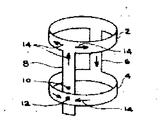
제2a도를 참조하면, 단일권선 새들 코일이 두 병력 도전성 세그먼트(21a)(22a)로 구성되는데, 그 각각은 직렬로 함께 연결되는 커패시터(23a)를 가진다. 도체(21a)(22a)의 단부들은 공통 세로축(16)을따라 간격진 한쌍의 도전성 루우프(25a)(26a)상에서, 직경상에서 대향진 점들에 연결된다. 코일은 세그먼트(21a)에서의 커패시터와 병렬인 단자(27a)(28a) 사이에 연결된 RF 증폭기(20)와 같은 전원에 의해 동작된다. 화살표(29)는 이하에서 수직이라고만 지칭될 도전성 도선 세그먼트(21a)(22a)에 의해 한정된 평면에 수직인 B1RF 자계를 발생하는 관련 전류 통로를 지칭한 것이다. B1자계의 방향은 종래의 오른손 법칙에 의해 결정된다. 그 오른손 법칙은, 만일 오른손의 손가락들이 전류 전송 세그먼트 주위에 놓이고, 엄지손가락 방향이 전류 방향이라면 손가락 방향이 자계(B1) 방향인 것을 의미한다.Referring to FIG. 2A, a single winding saddle coil consists of two forces conductive segments 21a and 22a, each having a capacitor 23a connected together in series. The ends of the conductors 21a and 22a are connected to opposite points in diameter on a pair of conductive loops 25a and 26a spaced along a common longitudinal axis 16. The coil is operated by a power source such as
본 발명에 따라 설게된 NMR 코일은 양호한 실시예에서, 제2b도에서 도시된 바와 같이 상부 및 하부 도전성 원형 루우프(25b)(26b) 주위에 연결되고, 균일한 간격으로 간격진 다수의 수직 도선 세그먼트(21b)를 포함한다. 루우프들은 정확히 원형일 필요는 없고 타원형 일수도 있음을 알아야 하며 검사될 물체를 그 안에 수용할 수 있는 개구를 가진 다른 형태일 수도 있는 것이다.The NMR coils constructed in accordance with the present invention are, in a preferred embodiment, a plurality of vertical lead segments connected around the top and bottom conductive circular loops 25b, 26b and spaced at uniform intervals, as shown in FIG. 2b. (21b). It should be noted that the loops need not be exactly circular, but may be elliptical, and may be of another type with an opening in which the object to be inspected can be accommodated.
수직 도전성 세그먼트들 각각은 적어도 하나의 용량성 소자(23b)를 갖는다. 제2b도에 것과 각각 대응하는 다중 전류통로들이 제2b도의 화살표(29)로 지칭되었고, 이것들에 대한 것은 이후 상세히 설명된다. B1자계의 균질성은 수직 도전성 세그먼트들의 수가 증가되면 될수록 증가한다. 이것은, 세그먼트수가 증가하면 그 결과의 자계가 여러 요인들에 의해 발생되어 한 도체의 효과가 감소되기 때문이다. 도체들의 수가 제한없이 증가될 수는 없는데, 그 이유는 인접수직 도체들의 사이 공간 간격이 전류흐름에 따라 자속이 지나가 균질 자계 B1를 발생할 필요성이 있기 때문이다. 4,8,16,32개의 수직 도체들을 가진 코일들이 만들어 질 수 있다. 수직 도체 세그먼트들은 동일 간격으로 간격질 필요가 있다. 실제로, 환자의 용이한 관측을 위해 코일안에 형성된 윈도우를 가진 본 발명의 RF 코일의 실시예가 이하 상세히 설명된다. 균질 B1자계를 발생하는데 필요한 것은 주변 도전성 루우프들 주위에 분포된 다수의 수직 도체들이 그 도체들 내의 전류가 정현파 분포를 이루도록 하는 것이다. 그 결과 본 발명의 코일은, 그 코일이 정현파 전압이나 전류에 의해 여자될 때 원통축에 대한 진동자계 횡파를 가진 단부가 개방된 원통으로 만들어진 공진 공동으로 생각될 수 있다. 이하 충분히 설명되는 바와 같이 다수의 가능한 공진 모우드가 있다.Each of the vertical conductive segments has at least one capacitive element 23b. Multiple current paths respectively corresponding to those in FIG. 2b have been referred to by
제2b도에 개략적으로 도시된 본 발명의 코일의 보다 완전한 이해가, 제3a도에 도시된 이 코일 구조에 대한 럼프 소자 등가 회로를 연구함으로, 이루진다. 그 등가회로는 일반적으로 제3b도에 번호(30)로 지칭된 반복회로로 구성된 평형 사다리 회로망이다. 각 유니트는 유도성 소자(31)(32)를 갖는데, 그 소자 각각은 각각 그 단부들에 연결된 유도성 소자와 용량성 소자(33)(34)의 직력 연결 조합을 갖는다.A more complete understanding of the coil of the present invention, shown schematically in FIG. 2B, is achieved by studying the Lump element equivalent circuit for this coil structure shown in FIG. 3A. The equivalent circuit is a balanced ladder network, generally consisting of a repeating circuit referred to by
제3a도에 A로 지칭된 두 점이 상부 도전성 루우프(26B)를 완성하도록 결합되고, B로 지칭된 두 점은 하부 도전성 루우프(25b)를 완성하도록 결합된다. 인덕터(31)(32)는 코일의 상부 및 하부 도전성 루우프를 따르는 각 루우프 세그먼트(24)와 관련된 인덕턴스를 표시한다. 이러한 인던터들은 모두 유도적으로 결합된다. 마찬가지로, 인덕터(33)는 수직 도선 세그먼트(21b)와 관련된 것으로 또한 상호 결합된다. 어느정도까지 수직 도선 세그먼트들은 제2a도에 도시된 단일 권선에 비교해 볼때 감소된 순수 인덕턴스를 지니고 병렬로 접속된다. 반면, 상호 결합은 상부 및 하부 도전 루우프의 순수 인덕턴스를 증가한다.(루우프들에서 개개의 자기유도의 합과 비교해서) 실제에 있어, 루우프 및 수직 세그먼트 인덕턴스는 둘다 도전성 막의 넓은 띠로 구성하여 최소화된다. 이것은, 유연성 인쇄뢰로판을 사용한 도체들을 부식하여 만들어질 수 있다. 제3a도의 인덕턴스(31)(32)(33)를 최소화하기 위해 코일의 동작 주파수를 올리는 것이 바람직하다.Two points, labeled A in FIG. 3A, are combined to complete the upper conductive loop 26B, and two points, referred to as B, are combined to complete the lower conductive loop 25b.
제3b도를 참조하면, 동작에 있어서, 점 E와 F 사이의 전압은 점 C와 D 사이의 전압에 대해 위상 이동되고, 전체 유니트(30)(제3a도)에 대한 누적된 위상 이동이 더해져 2π 라디안이 되는 주파수에서, 코일은 정상파 공진을 가진다. 이런 공진에서, 즉 1차 공진에서, 각각의 도선 세그먼트(21b)의 전류는 sin θ에 비례하는 것이 알려졌다. 여기에서 각도 θ(제2b도 참조)는 예를 들면 Y 축으로부터 측정된 수직 도선 세그먼트의 극좌표 각도이다. 그러한 정현파 전류 분포는 수직 도선 세그먼트(21b)들의 수가 증가하면 더욱 증가하는 균질 횡 자계를 발생한다.Referring to FIG. 3B, in operation, the voltage between points E and F is phase shifted with respect to the voltage between points C and D, and the accumulated phase shift with respect to the entire unit 30 (FIG. 3A) is added. At frequencies that are 2π radians, the coil has standing wave resonance. In this resonance, i.e., the primary resonance, it is known that the current in each lead segment 21b is proportional to sin θ. Here the angle θ (see also FIG. 2b) is the polar coordinate angle of the vertical lead segment measured from the Y axis, for example. Such sinusoidal current distribution produces a homogeneous transverse magnetic field that increases further as the number of vertical lead segments 21b increases.
제3a도의 점프 소자등가 회로로 표시된 코일 구성은 고차 횡파 자계분포를 발생하는 높은 주파수 공진 현상을 보여준다. 보다 높은 공진 주파수는 적당한 고주파 여기 전원을 사용해서 여기된다. 그러한 공진은 2차공진이라 부른다. 예를 들면, 회로망 주위에 누적한 위상 이동이 4π 라디안이 될 때, 수직 도선 세그먼트에서의 전류는 2θ에 비레한다. 이런 공진에 대해, 횡파 자계의 X,Y 성분은 대략 각각 X축, Y축을 따라 코일의 중앙에서 O를 갖는 선형 그래디언트를 보여준다.The coil configuration, represented by the jump element equivalent circuit of FIG. 3A, exhibits a high frequency resonance phenomenon resulting in higher order transverse magnetic field distribution. Higher resonant frequencies are excited using a suitable high frequency excitation power supply. Such resonance is called secondary resonance. For example, when the phase shift accumulated around the network becomes 4 [pi] radians, the current in the vertical lead segment is proportional to 2 [theta]. For this resonance, the X, Y components of the transverse magnetic field show a linear gradient with O at the center of the coil, approximately along the X and Y axes, respectively.
제3a도의 점프 소자 등가 회로망을 표시한 특정 세트의 방정식들이 분석되어 풀어지는지는 아직 알려지지 않았다. 그런, 주기적 구조를 가진 파의 전파는 광범위하게 연구되었는데, 특히 고체물리학에서 점프 소자등가 회로에서 전류분포를 직관적으로 기술한 것을 지지해주고 있다. 사다리 회로망의 단부(A와 B, 제3a도 참조)를 연결하여 상부 및 하부 루우프를 발생하는 것은 결정 격자 이론에서 자주 사용되는 주기적인 경게 조건을 부과해준다.It is not yet known whether a particular set of equations representing the jump element equivalent network of FIG. 3a are analyzed and solved. Such propagation of periodic wave structures has been extensively studied, especially in solid-state physics, which supports the intuitive description of current distribution in jump-element equivalent circuits. Generating the upper and lower loops by connecting the ends of the ladder network (see also A and B, see also FIG. 3a) imposes periodic cyclic conditions often used in crystal lattice theory.
2N 반복 소자(30)에 대해 (2N+1)루우프 전류와(2N+1) 선형 방정식이 존재한다. 만일 루우프(25b)(26b)의 전류가 평형을 이룬다면 1루우프 전류는 0으로 설정될 수 있다.For the
2N의 잔류 방정식들은 N 쌍의 고유해를 갖는 2N×2N 토플리쯔(Toeplitz) 매트릭스로 표시된다. 고유전류들은 sin nθ와 1<n<n내에서 비례한다. 그 방정식들의 숫치(numerical) 해답은 전류가 정현적임을 보여준다.Residual equations of 2N are represented by a 2N × 2N Toeplitz matrix with N pairs of intrinsic solutions. The intrinsic currents are proportional to sin nθ and 1 <n <n. The numerical solution of the equations shows that the current is sinusoidal.
만일 원통이 4중 원통 대칭 구조를 갖도록 구성되면 몇가지 잇점이 발생된다. 여기에서 사용된 바와 같이, 4중 원통 대칭이란 것은 코일구조(루우프 주변을 따라 수직 세그먼트의 위치와 각각의 세그먼트내의 용량 값)가 그 세로축에 관해 90°회전하여도 동일한 구조라는 것을 의미한다.If the cylinder is configured to have a quadruple cylinder symmetry, several advantages arise. As used herein, quad cylindrical symmetry means that the coil structure (the position of the vertical segment along the loop periphery and the capacitance value in each segment) is the same structure even when rotated 90 ° about its longitudinal axis.
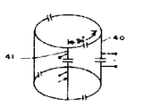
예를 들면 4의 배수(4,8,12,16,32 등) 인 수직 세그먼트들을 가진 코일은 4중 대칭이다. 이 경우에, 1차 공진은 동일 공진 주파수에서 2 직각 축퇴 모우드를 가진다. 그 하나는 여기에서 X모우드라 칭하는데, 그것은 수직 도선의 전류가 sin θ에 비레할 때 X축에 평행한 RF 자계를 제공한다. 다른 모우드에서, 즉 Y 모우드에서, 전류는 cos θ에 비례하고, 자계는 Y축 방향내에 있다. 만일 RF 코일이, 제2b도에 도시된 단자(27b)(28b) 사이에서와 같이, 단일점에서 RF 증폭기(도시 안됨)로 부터 전력을 공급하여 동작되면, 오직 X 모우드만이 여기된다. 이 경우 공진회로는, 각각이 크기에서 H1이 B0자계의 방향에 수직인 횡 평면내에서 반대방향으로 회전하는 두 자계로 생각되는, 진동 RF 계 2H1coswt를 발생한다. 핵은 2 회전 자계 중의 하나에만 반응하나. 그러므로, 잘못된 방향으로 회전하는 B1성분을 발생하도록 사용된 전력은 낭비되나. 그러나, 만일, 제4도와 같이, 코일이 수직 도체(40)내의 제1구동점으로부터 90°떨어져 위치된 수직 도체(41)내의 제2구동점에서 전원과 90°위상차로 전력이 공급되면, 두 진동 자계는 벡터 법칙으로 가산되어 단일 회전 자계를 제공한다. 이 경우, 구동 전력에서 소비는 없을 것이다. 그러므로, 90°만큼 떨어진 두 구동점들에서 본 발명의 RF 코일을 구동하면 RF 전력 효율은 두배로 된다. 또한, 두 직각 모우드에서 발생된 잡음 전압이 상호 관련되지 않고, 핵으로부터의 신호가 상호 관련됨으로, 신호대 잡음비는 2 배 만큼 향상된다. 이 경우, 검출된 NMR 신호는 코일의 두 직각 점에서 샘플된다.For example, a coil with vertical segments that are a multiple of four (4, 8, 12, 16, 32, etc.) is quadratic symmetric. In this case, the primary resonance has two orthogonal degenerate modes at the same resonance frequency. One is referred to herein as the X-mode, which provides an RF magnetic field parallel to the X-axis when the current in the vertical lead is sin θ. In the other mode, ie in the Y mode, the current is proportional to cos θ and the magnetic field is in the Y axis direction. If the RF coil is operated by powering from an RF amplifier (not shown) at a single point, such as between the
2축퇴 X,Y 공진 모우드들에 대한 수직성을 유지하기 위해서 부품의 허용 오차와 코일의 기하학 구조상에 제한 조건을 가하게 된다. 예를 들면, 두 모우드 사이에 유도 결합의 유효계수 K가, 코일의 Q값의 역수에 비교해서 작게 유지되어야 한다. 코일의 환자 부하가 높고, RF 전력 효 율이 낮은게 더욱 바람직한 고주파에서, 코일의 낮은 Q 값은 수직성을 달성하는 제한 조건을 약간 완화시킨다.In order to maintain perpendicularity to bi-degenerate X, Y resonant modes, constraints are placed on the component tolerances and the geometry of the coil. For example, the effective coefficient K of the inductive coupling between two modes should be kept small compared to the inverse of the Q value of the coil. At high frequencies, where the coil's patient load is high and RF power efficiency is more desirable, the low Q value of the coil slightly mitigates the constraints of achieving verticality.
두 공진 모우드는, K×Q 적이 5% 보다 낮다면, 본질적으로 결합되지 않는다. 이 경우, 각 모우드는 회전자계를 발생하기 위해 정확한 위상 이동을 갖을 것이다. 8개의 수직 도체를 가져 4중 대칭을 가진 코일용 수직 및 루우프 도체들내에서 전류들의 방향은 그러한 코일을 보여주는 제2b도에서 화살표(29)로 표시되었다. 이러한 전류의 정현파 성질이 제5a도 내지 제5c도를 참조해서 이하 상세히 기술된다. 위치 θ=0°도 임의로 설정한 세그먼트내에 있는 점(27b)(28b) 들에서 앞서 언급한 바와 같이 코일이 전력을 공급받으면, cos θ에 비레한 최대 전류가 θ=0°에 위치된 세그먼트 내에서 원형내 점으로 표시된 바와 같이 지면으로부터 나오는 방향으로 흐른다. θ=45°와 315°에서 cos θ에 비례한 작은 전류는 θ=0°에 위치된 것의 인접 세그먼트내에서 동일 방향으로 흐른다. 대응 크기의 전류들이 대향 방향으로(십자표시로 표시된 것처럼 지면 속으로) θ=180°,135°, 225°에 위치된 세그먼트 내에서 흐른다.The two resonant modes are essentially uncoupled if the K × Q product is less than 5%. In this case, each mode will have the correct phase shift to generate the rotor field. The direction of the currents in the vertical and loop conductors for the coil with eight vertical conductors with quadruple symmetry is indicated by
도전성 세그먼트들내에서 흐르는 전류의 크기는, 위치각 θ가 수평축으로 표시되고, 전류 크기가 수직축으로 표시된 제5b도에 도시된다. 지면으로 부터 흐르는 전류들(45°,0°,315°)은 임의로 +값으로 표시된 반면, 지면 속으로 흐르는 전류들은 -값으로 표시되었다. 1차 공진 모우드에서, θ=90°, =270°에 있는 세그먼트들은 어떤 전류도 도통시키지 않는다. 실제로 그것들은 제거되고, 단락된 회로로 대체된다.The magnitude of the current flowing in the conductive segments is shown in FIG. 5B where the position angle θ is indicated on the horizontal axis and the magnitude of the current is indicated on the vertical axis. Currents flowing from the ground (45 °, 0 °, 315 °) are arbitrarily marked with a positive value, while currents flowing into the ground are indicated with a negative value. In the primary resonant mode, the segments at θ = 90 °, = 270 ° do not conduct any current. In practice they are removed and replaced by short circuits.
상부 도전성 루우프(26b)(제5a도)에 흐르는 전류 흐름 방향은 대략의 크기를 표시하기 위해 서로에 대해 크기 표시가 된 화살표(50)로 표시된다. 더욱, 루우프 전류분표는 각각 수평 및 수직축을 따라 표시된 각도 위치 및 전류크기를 나타내주는 제5c도에 상세히 도시된다. 그러므로, 45°와 90°사이의 전류, 315°와 270°사이의 전류는 각각 0°와 45°사이의 전류와 0°와 315°사이의 전류 보다 큰데, 그 이유는 전자의 전류들이 45°와 315°에서의 세그먼트들에 의한 전류를 포함하기 때문이다.The direction of current flow through the upper conductive loop 26b (FIG. 5A) is indicated by
어떤 실시예(제5d도 참조)에서는 특히 머리부분 영상화용 NMR 에 쓰이는 코일들에 있어서, 환자의 얼굴을 쉽게 볼수 있는 수단으로 코일틀 내에 윈도우를 절결하는 것이 유익하다고 알려졌다. 이것은 윈도우를 절결하기 위해 수직 세그먼트들 중 몇 개를 제거하는 것을 필요로 한다.In some embodiments (see also 5d) it has been found to be advantageous to cut out the window in the coil frame as a means of easily seeing the patient's face, especially for coils used for head imaging NMR. This requires removing some of the vertical segments to cut out the window.
이것이 이후 기술될 실시예에서 32 세그먼트들과 같은 밀접히 간격진 수직 세그먼트들을 가진 코일의 참 모습이다.This is the true appearance of the coil with closely spaced vertical segments such as 32 segments in the embodiment to be described later.
RF 자계의 균질성의 섭동을 최소화하기 위해, 전류를 흘리지 않거나 거의 흘리지 않는 그러한 세그먼트들을 제거하는 것이 바람직하다. 제5a도에 도시된 실시에에서, 90°나 270°에 위치된 도체중 하나가 계의 균질성을 해하지 않고 제거될 수 있다. 90° 세그먼트가 제거된 이 경우에 수직 세그먼트들내의 전류분포는 제5e도에 도시된다. 135°보다 작고 45°보다 큰 점들에서 전류 크기는 0이다.In order to minimize the perturbation of the homogeneity of the RF magnetic field, it is desirable to remove those segments that pass little or no current. In the embodiment shown in FIG. 5A, one of the conductors located at 90 ° or 270 ° can be removed without compromising the homogeneity of the system. In this case the 90 ° segment has been removed, the current distribution in the vertical segments is shown in FIG. 5E. At points less than 135 ° and greater than 45 °, the current magnitude is zero.
32 수직 세그먼크들을 가진 실시예에서, 6 세그먼트들은 윈도우를 수용하도록 제거된다. 이 코일이 어떤 제어조정없이 만족스럽게 동작되는 것이 발견되었다. 양호한 실시예에서, 그러나, 제거된 세그먼트드리 제거된 전류 이송 용량에 대한 보상을 하기 위해, 증가된 전류를 수용하기 위해 윈도우 양측사에서 가장 가까운 세그먼트들내의 용량값을 증가시키는 것이 유익하다고 알려졌다.In an embodiment with 32 vertical segments, 6 segments are removed to accommodate the window. It has been found that this coil operates satisfactorily without any control adjustments. In a preferred embodiment, however, it has been found to be beneficial to increase the capacitance value in the segments closest to both sides of the window to accommodate the increased current in order to compensate for the removed segment.
어떤 머리(헤드)코일 실시예에서, 루우프 소자들중 하나를 구부려 일반적으로 새들형인 구성으로 하는 것이 바람직하다. 볼록산 루우프 부분(제5d도에서 J,K 부분)은 머리가 보다 완전히 코일로 둘러쌓이도록 어깨 부분들에 맞도록 되어 있다. NMR 헤드 코일에서 코일을 두 분리 가능한 코일 조립체로서 만드는 것이 유리하다고 밝힌 본 출원인에게 양도된 현재 출원중인 미국출원(G.E 번호 15-NM-2442, 본 발명의 배경으로 여기에서 참조로 수록함)에 기재되었다. 이 경우에, 제6a도에서 도표시된 것처럼 점 X, Y에서 상부 및 하부도체들로 개방회로롤 구성하는 것이 필요하다. 코일은 또한 θ=0 에서 에너지를 받아 동작중에 개방회로로 부터 반쪽의 두 코일은 단일 코일로 동작하도록 상호 인덕턴스로 결합된다.In some head coil embodiments, it is desirable to bend one of the loop elements into a generally saddle-like configuration. The convex-loop part (J, K in Figure 5d) is adapted to the shoulders so that the head is more completely surrounded by the coil. Described in the currently pending US application (GE No. 15-NM-2442, incorporated herein by reference for the background of the present invention) assigned to the applicant who found it advantageous to make the coil as two separate coil assemblies in an NMR head coil. It became. In this case, it is necessary to construct an open circuit with upper and lower conductors at points X, Y as shown in figure 6a. The coil is also energized at θ = 0 and in operation, the two halves of the coil from the open circuit are coupled in mutual inductance to act as a single coil.
제6a도는 제5a도와, 루우프 개방회로들로 인해 90°와 270°의 세그먼트들이 반대한향의 전류들을 이송하는 점을 제외하고는, 서로 유사하다. 이전 실시예에 대한 세그먼트 전류분포는 제6b도에 도시되고, 앞서의 예와 같이 θ=0°, 45°, 180°, 225°, 근처의 세그먼트들에 발생하는 최대 전류를 가지고 각도 θ에 의존하는 정현파적 기하 구조를 갖는다. 제6c도는 도전성 루우프 소자들의 전류분포를 도시한다. 최대 루우프 전류값은 W로 지칭된 90°, 270°보다 약간 큰 Q 값에서 발생한다.FIG. 6a is similar to FIG. 5a, except that segments of 90 ° and 270 ° carry opposite currents due to the loop open circuits. The segment current distribution for the previous embodiment is shown in FIG. 6b and depends on the angle θ with the maximum current occurring in the segments near θ = 0 °, 45 °, 180 °, 225 °, as in the previous example. Has a sinusoidal geometry. Figure 6c shows the current distribution of the conductive loop elements. Maximum loop current values occur at Q values slightly greater than 90 °, 270 °, referred to as W.
만일 원한다면, 윈도우가 가장 낮은 전류 이송 도전성 세그먼트를 제거함으로 제6a도에 도시된 코일 실시예내에 형성될 수 있다. 그러한 세그먼트들은 제6a도에 W로 지칭된 지역으로 표시된 바와 같이 90°와 135°, 270°와 315°사이에 위치된다. 제6b도에서, 최소 전류들을 가진 세그먼트들에 이러한 지역들이 대응하고, 따라서 RF 계의 균질성에 최소 충격을 주는 것을 도시된다.If desired, a window can be formed in the coil embodiment shown in FIG. 6A by removing the lowest current carrying conductive segment. Such segments are located between 90 ° and 135 °, 270 ° and 315 ° as indicated by the area labeled W in FIG. 6A. In FIG. 6B, these regions correspond to segments with minimum currents, thus giving a minimal impact on the homogeneity of the RF system.
만일 코일구조(즉, 루우프 주변을 따라 수직 세그먼트들의 위치나 각각의 세그먼트내의 커패시터 용량 값)가 4중 대칭 구조와 다른 구조로 선택된다면, X와 Y 공진 모우드들은 직교하고, 상이한 주파수에서 발생한다. 두 공진을 여기하는 한 가지 방법은 앞서 기술한 바와 같이 두 발생원을 가지고 하는 것이다. 그러나, 필요한 주파수 성분을 가진 단일 발생원을 사용해서 두 공진을 여기하는 것도 가능하다. 성분값에서나 코일구조에서 작은 변화도 코일 Q 값이 충분히 크다면 중첩 공진을 발생할 수 있다. 이것은 단일 전원만 필요하다면 문제가 될 수 없다. 그런, 만일 코일 대칭이 순수하게 섭동된다면 무해하도록 주파수에서 두 공진중 하나가 충분히 변위될 수 있다. 한 가능성은 소망의 모우드가 전류 0을 가진 점들에서 상부 및 하부 도전성 링(25b)(26b)(제2b도)을 절결하는 것이다. 다른 가능성은 소망의 모우드에서 단락 회로들에 의해 아무 전류도 이송하지 않는 커패시터들(23b)을 교체하는 것이다. 단락회로된 세그먼트는 유효하게 큰 용량으로 나타나게 되어 바람직하지 않은 모우드의 공진 주파수를 낮춘다. 개방회로의 효과는 나타난 용량을 감소시키고, 공진 주파수를 증가시키는 것이다.If the coil structure (i.e. the position of the vertical segments along the loop or the capacitor capacitance value in each segment) is chosen to be different from the quadratic symmetry structure, the X and Y resonant modes are orthogonal and occur at different frequencies. One way to excite two resonances is to have two sources as described above. However, it is also possible to excite two resonances using a single source with the required frequency components. Even small changes in component values or coil structure can cause overlapping resonances if the coil Q value is large enough. This can't be a problem if only a single power supply is needed. However, if the coil symmetry is purely perturbed, one of the two resonances can be sufficiently displaced in frequency to be harmless. One possibility is to cut off the upper and lower conductive rings 25b and 26b (FIG. 2B) at the points where the desired mode has current zero. Another possibility is to replace capacitors 23b which carry no current by short circuits in the desired mode. Short-circuit segments appear to be effectively large in capacity, lowering the resonant frequency of the undesirable mode. The effect of the open circuit is to reduce the displayed capacitance and increase the resonant frequency.
커패시터들(23b)을 적당히 선택함으로 두 공진 주파수를 조정하는 것이 비대칭 4중 구조에서는 유리할 것이다. X 모우드는, Y 모우드가 최소전류를 가지는 곳에서 최대 전류를 가진다. 그러므로, sin θ가 큰 커패시터를 증가시키고, cos θ가 큰 커패시터를 감소시킴으로서, X 모우드 주파수는 낮춰지고, Y-모우드 주파수는 올라간다. 그러한 코일은 NMR 이중(중첩) 공진 연구를 동시에 수행하는 데 유용하다.Adjusting the two resonant frequencies by suitably selecting the capacitors 23b would be advantageous in an asymmetric quadruple structure. The X mode has the maximum current where the Y mode has the minimum current. Therefore, by increasing the capacitor with large sin θ and decreasing the capacitor with large cos θ, the X-mode frequency is lowered and the Y-mode frequency is raised. Such coils are useful for simultaneously conducting NMR double (overlapping) resonance studies.
예를 들면, 한 모우드는 양성자1H 공진용으로 동조되고, 다른 모우드는 불소19F 공진용으로 동조 될 수 있다.For example, one mode can be tuned for proton 1 H resonance and the other can be tuned for fluorine 19 F resonance.
본 발명의 NMR 코일 설계는 원리상 생체 실험 NMR 연구에서 여러 가지 방법으로 실행될 수 있다. 양호한 실시예에서, 도전성 소자들(예를 들면, 21b, 25b와 26b, 제2b도)은 그들의 자기 유도를 최소화 하기 위해 도전성 막의 넓은 폭의 판으로 만들어진다.The NMR coil design of the present invention can, in principle, be implemented in a variety of ways in in vivo NMR studies. In a preferred embodiment, the conductive elements (eg, 21b, 25b and 26b, FIG. 2b) are made of a wide plate of conductive film to minimize their magnetic induction.
예를 들면 또한 그들은 큰 직경을 가진 도전성 관으로 만들수 있다. 상부 및 하부 도전성 링들 사이의 거리는 루우프(25b)(26b)들의 전류로 인한 계의 불균질성을 감소시키기 위해 코일 직경보다 1배 이상이어야 한다.They can also be made of conductive tubes with large diameters, for example. The distance between the upper and lower conductive rings should be at least one times the coil diameter in order to reduce the heterogeneity of the system due to the current in the loops 25b and 26b.
만일 단일한 소정의 주파수로 코일의 공진하게 한다면, 고정 커패시터만을 사용해서 제2b도 이후의 코일 패턴으로 만들어지는 것도 가능하다. 그러나, 공진 주파수의 미세한 조정을 위해 실제로 몇개의 가변 소자들을 포함하는게 좋다.If the coil is to be resonated at a single predetermined frequency, it is also possible to make the coil pattern of Fig. 2b later using only a fixed capacitor. However, it is better to actually include several variable elements for fine adjustment of the resonant frequency.
X, Y 모우드 둘 모두를 동조하는데 최소 요건은 90°떨어진 두 수직도전성 소자들(예를 들면 제4도의 (40)(41))의 각각에서 가변 조정 커패시터를 위치시키는 것이다.이러한 두점들에서 용량에서의 작은 섭동은 계의 균질성을 크게 해치지 않는다.The minimum requirement for tuning both X and Y modes is to place the variable regulating capacitor in each of the two vertically conductive elements (e.g. (40) (41) of FIG. 4) that are 90 degrees apart. The small perturbation in Es does not significantly compromise the homogeneity of the system.
공진 주파수를 광범위하게 조정하는 것이 필요한 경우, 동시에 모든 커패시터들을 동조하거나, 코일 조립체의 유효 인덕턴스를 변화시키는 것이 좋다. 인덕턴스에서의 작은 변화는 도전성 소자들의 막의 폭을 변화시킴으로 달성된다. 인덕턴스에서의 큰 변화는 두 도전성 루우프 사이의 거리를 조정함으로 수직 도체의 길이를 변화시켜 얻는다.If it is necessary to adjust the resonant frequency extensively, it is advisable to tune all capacitors at the same time or to change the effective inductance of the coil assembly. Small changes in inductance are achieved by changing the film width of the conductive elements. The large change in inductance is obtained by changing the length of the vertical conductor by adjusting the distance between the two conductive loops.
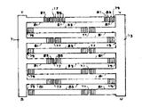
32세그먼트들을 가지며, NMR 머리부분 연구에 쓰이는 물리적 및 전기적 크기를 갖는 본 발명의 코일 제조방식이 제7a도와 제7b도를 참조로 이제 설명된다. 더 큰 직경을 가진 코일 몸체 구성 방식도 동일한 구성 방식을 따른다. 머리 부분용 코일(이하 헤드코일이라 칭함)은 주자계 B0의 강도에 의해 결정되는 NMR 동위원소연구에 쓰이는 21, 31 MHz 주파수에서 동작한다. 일반적으로, 코일은 4 이중양면 구리-클래드테플론 수지 인쇄 회로판을 에칭(종래에 사용된 기법)하여 만든다. 그 회로판은 10.5인치(약 27센티미터)의 외경을 가진 원통상에 설치된다. 인쇄판의 각면은 상이한 도전성 패턴으로 에칭된다. 각 회로판은 약 8×12인치 규격이다.The coil fabrication method of the present invention having 32 segments and having physical and electrical dimensions for NMR head studies is now described with reference to FIGS. 7a and 7b. Coil body configurations with larger diameters follow the same configuration. The head coil (hereinafter referred to as the head coil) operates at 21 and 31 MHz frequencies used in NMR isotope studies, which are determined by the strength of the main magnetic field B 0 . Generally, coils are made by etching four double-sided copper-clad teflon resin printed circuit boards (a technique conventionally used). The circuit board is mounted on a cylinder with an outer diameter of 10.5 inches (about 27 centimeters). Each side of the printing plate is etched with a different conductive pattern. Each circuit board is approximately 8 x 12 inches.
제7a도를 참조하면, 원통상에 형성된 회로판의 한쪽(이하 내부 에치면이라 칭함)을 에칭하는데 쓰이는 도전성 패턴이 도시된다. 넓은 스트립(71), (73)들은 각각이 7/8인치 폭을 가지고, 도전성 루우프 소자들의 길이의![]()
![]()
제 2 갭 (79)이 대응 루우프 소자로 부터 직선 소자의 그 나머지![]()
![]()
또 다른 패턴이 제7b도에 도시되며, 이후 외부 에치면이라 그것을 칭한다. 이 패턴은 제7a도의 패턴의 거울 영상이고, 그것과 동일한 칫수를 갖는다. 제7b도의 패턴이 제7a도의 것과 다른 점은 직선 도체부분(81)(83)이, 좁은 갭들로 에칭함으로 형성된 전형적으로 4개의 (그 이상이나 이하가 사용될 수 있지만) 구리 패드들(85)을 각각 가지고 있는 점이다.Another pattern is shown in FIG. 7B, hereinafter referred to as outer etch surface. This pattern is a mirror image of the pattern of FIG. 7A and has the same dimensions as it. The pattern of FIG. 7B differs from that of FIG. 7A in that the
내부 및 외부 에치면은 점 S, T, U, V가 점 O, P, Q, R 위에 각각 놓이도록 겹친다. 이런 방식으로 각각의 에치면(외부 및 내부면)상의 갭(77)이 각 면상에서 직선 소자(75)의 연결안된 2/3(83) 연속 부분과 연결된다. 갭(79)은 직선소자의 연속부분(71)과 연결된다. 구리막 세그먼트들과 인쇄회로 유전체와 조합은 각 직선도체의 길이를 따라 3직렬 연결된 커패시터를 형성한다. 각 직선 도체내의 순수 커패시탄스(용량)는 대략 같게 동조된다. 그 조성은 내부 및 외부면들의 중첩 지역을 변화시키기 위해 구리패드(85)들을 전기적으로 하나 이상 연결해서 달성된다. 양호한 실시예에서, 내부 및 외부 패턴은 이중면 인쇄회로 기판의 양측상에 형성된다.The inner and outer etch faces overlap so that points S, T, U, and V lie on points O, P, Q, and R, respectively. In this way a
스트립(71)(73)의 내부 및 외부 에치면들은 점 O와 S, P와 T, Q와 U, R과 V에서 함께 전기적으로 연결된다. 하나의 완전한 코일은 그러한 중첩된 상호 연결된 4개의 조립체를 필요로 한다. 반 코일은 전기적으로 2개의 조립체를 결합해서 만들어진다. 1/4 조립체의 점 O와 Q은 제 2 의 1/4 조립체의 각각의 점 P와 R에 전기적으로 연결된다. 이런 방식으로 구성된 2코일 반쪽들은 그들 사이에 전기 접속없이 원통 코일 형상에 설치된다.The inner and outer etch surfaces of
루우프도체들을 두개의 반쪽으로 남겨두는 것은 앞서 언급한 바와 같이 2개의 바람직한 공진의 축퇴를 분리시킨다. 두 코일 반쪽들은, 동작시, 그중 하나가 예를 들면 (89)(91)(제7a도)의 점들에서 직선 도체내의 3커패시터중 하나의 양단에서 에너지를 받을때, 그들의 상호 유도에 의해 결합된다. 구동점 임피던스는 코일(부하된 코일)내의 환자 머리와 어떤 조정 없이 약 50 오옴이다.Leaving the loop conductors in two halves separates the decay of the two preferred resonances as mentioned above. The two coil halves are coupled by their mutual induction when in operation one of them receives energy across one of the three capacitors in the straight conductor, for example at the points (89) (91) (Fig. 7a). . The drive point impedance is about 50 ohms without any adjustment with the patient's head in the coil (loaded coil).
양호한 실시예에서, 이중면 인쇄회로판 유전체(테플론 수지) 두껜느 약 0.006인치이다. 각각의 직선 도체안에 3커패시터들 각각은 대략 133 피코파라드로 조정된다. 각 커패시터가 동일값을 가지는 것이 중요한 것이 아니라 각 직선 도체의 순수 용량이 동일한 것이 중요한다. 균질한 RF 자계에서 소망의 공진 주파수는 21.31 MHz이다.In a preferred embodiment, the double-sided printed circuit board dielectric (Teflon resin) thickness is about 0.006 inches. Each of the three capacitors in each straight conductor is adjusted to approximately 133 picoparads. It is not important that each capacitor has the same value, but that the net capacity of each straight conductor is the same. In a homogeneous RF magnetic field, the desired resonant frequency is 21.31 MHz.
본 발명의 NMR 코일의 다른 실시예가 32 수직 세그먼트를 가진 제7a도, 제7b도에 도시된 형태를 뒤이어 구성된다. 이 코일은 11.5 인치 외경과 16.5인치 길이를 가진 원통상에 구성된다. 스트립(71)(73)(제7a도, 제7b도)은 0.25인치폭을 가진다. 직선 도체(75)는 5/8 인치 간격으로 간격진 0.5인치 폭을 지닌다. 이 경우, 각 직선도체에 10개의 갭이 있다. 이 갭은 갭(77)과 (79)와 유사해서 각 커패시터 값은 제7a도 및 제7b도의 실시예의 것보다 낮다. 코일 공진 주파수는 63.86MHz이다.Another embodiment of the NMR coil of the present invention is constructed following the configuration shown in FIGS. 7A and 7B with 32 vertical segments. The coil is constructed on a cylinder with an outer diameter of 11.5 inches and a length of 16.5 inches.
물론 본 발명의 개념에 대해 여기에서 밝힌 구성은 단순히 양호한 실시예로서, 실제로는 이 분야에 익숙한자들에 의해 여러가지 다른 방법이 있을 수 있음을 알아야 한다. 몇가지 예를 들면 제8a도와 제8b도, 제9a도와 제9b도, 제10도와 제11도를 참조로 이후 그 구성 방법이 설명된다.Of course, it is to be understood that the configurations disclosed herein for the concepts of the present invention are merely preferred embodiments, and that in practice there may be many different ways by those skilled in the art. Some configuration examples will be described below with reference to FIGS. 8A, 8B, 9A, 9B, 10 and 11.
제8a도는 상호 연결 도전성 루우프(102)(103)의 주변을 따라 동일 간격으로 간격진 수직도체(101)들을 가진 한 코일 실시예를 도시한 것이다. 각각의 도체(101)는 그것의 길이내에 형성된 가변 커패시터(104)가 형성된다.8A illustrates one coil embodiment with
제8b도는 한 가능한 구성을 보여준 가변 커패시터의 상세 종단면도이다. 그 커패시터는 내부도체부(101a)가 형성되고, 그 내부 도체부의 한 단부는 도체부(101b)의 종공부(107)속으로 연장한다. 도체(101a)(101b)의 다른 단부들을 도전성 루우프(102)(103)에 연결된다. 부분(101a)은, 수정이나 다른 적당한 유전체를 포함한 테플론 합성수지 중합체와 같은 유전체(108)로 형성한 슬리이브에 의해 도체(101b)의 중공부의 내부면으로부터 분리된다. 수직 도체(101)의 수는 물론 커패시터(104)의 수가 8과 32사이의 수(이것에 의해 제한되지 않음)로 선택된다.8B is a detailed longitudinal cross-sectional view of the variable capacitor showing one possible configuration. The capacitor is formed with an inner conductor portion 101a, and one end of the inner conductor portion extends into the
모든 커패시터들은 그 장치의 길이를 변화시켜 동시에 조정될 수 있다. 길이와 함께 인덕턴스에서의 변화는 용량에서의 변화보다 보다 작은 효과를 나타낸다. 물론, 단일 공진 주파수만 필요하다면, 각각의 수직 도체(이 실시예에서나 이하 가술될 실시예에서)는 그와 관련된 가변 커패시터가 필요하지 않을 수도 있음을 이해해야한다.All capacitors can be adjusted simultaneously by varying the length of the device. Changes in inductance along with length have a smaller effect than changes in capacity. Of course, if only a single resonant frequency is needed, it should be understood that each vertical conductor (in this embodiment or in the embodiment to be described below) may not need a variable capacitor associated therewith.
제9a도와 제9b도를 보면 용량 변화보다 인덕턴스변화로 동조되는 본 발명의 NMR RF 코일의 다른 실시예가 도시된다. 코일은 각각이 단부에서 한쌍의 고정 커패시터를 가진 다수의 평행 수직 도체(110)들을 포함한다. 그 도체들은 한쌍의 평행 도전성 루우프(112)(113)의 주변에 평행으로 간격져 있으나 그 단부에서 한쌍의 커패시터를 형성하기 위해 진기적으로 절연된다. 제9b도는 커패시터가 형성된 방식을 상세히 도시한 것이다. 도체(110)의 각각은 예를 들면 루우프(112)내에 형성된 구멍(114)들을 통해 연장한다. 도체(110)는 구멍(114)을 따라 유전재로 만든 슬리이브(115)에 의해 도전성 루우프로 부터 전기적으로 분리된다.9A and 9B show another embodiment of the NMR RF coil of the present invention tuned to an inductance change rather than a capacitance change. The coil comprises a plurality of parallel vertical conductors 110 each having a pair of fixed capacitors at the ends. The conductors are spaced parallel to the periphery of the pair of parallel
코일은 단부 루우프(112)(113) 둘다른 서로 가깝게 하거나 멀리해서 또는 하나를 그렇게 이동함으로 동조될 수 있다. 이것은 코일의 용량을 변화시키지 않고서 인덕턴스를 변화시킨다.The coils may be tuned by bringing the
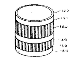
본 발명의 RF 코일의 다른 실시예가 제10도에 개략적으로 도시되었다. 이 실시예에서, 다수의 평행 도체(120)가 그 단부(121)에서 전기적으로 단락되며, 유전체 원통(122)의 외면상에 붙여지거나 에치된다. 유사한 원통(124)은 원통(122)의 직경보다 더 약간 작은 직경을 가진다. 그것은 또한 그들의 단부(126)에서 단락된 다수의 평행 도체(125)가 그위에 플레이트된다. 원통(122)의 직경보다 더 작은 직경을 가진 원통(124)은 그 원통안에 미끌어질 수 있게 삽입되어 도체(120)과 (125)의 단락되지 않은 단부들이 중첩된다.Another embodiment of the RF coil of the present invention is schematically illustrated in FIG. In this embodiment, multiple
대응 정합 도선들 사이의 용량은 도체(120)와 (125)사의 중첩 정도에 따른다. 도선의 정렬된 때그 도선을 넣거나 빼어서(인덕턴스와 용량을 변화시키므로)또는 도체를 잘못 정렬되게 하나에 대해 다른 하나를 회전시킴으로 용량을 변화시킴으로 동조된다.The capacitance between the corresponding mating leads depends on the degree of overlap of the
제11도는 병렬 고립된 도체(130)들이 유전체 원통(132)의 외면에 플레이트된 본 발명의 NMR RF 코일의 또 다른 실시예를 도시한 것이다. 한쌍의 도전성 루우프(133)(134)는 점선(135)(136)으로 표시한 위치까지 원통의 각 단부들 속으로 삽입되어, 원통벽을 포함한 유전체를 통해 도선들에 대해 용량적으로 결합된다. 원통의 세로축을 따라 루우프들을 속으로 또는 밖으로 이동시켜 우루프와 도체 사이의 중첩도를 변화시켜 용량을 변화시킴으로 그 장치는 동조된다. 또한 그 장치는 수직 도체(130)의 길이를 뱐화하기 위해 적어도 루우프들중 하나를 미끄러지게 하여 유도적으로 동조된다. 도체(130)는 원통 내부상에 위치될 수 있는 반면 도전성 루우프는 원통의 외측에 위치될 수 있음을 알아야 한다.FIG. 11 illustrates another embodiment of the NMR RF coil of the present invention in which parallel
지금까지 설명된 모범적인 NMR 코일 실시예들 각각에 있어서, 중첩도를 변화시키거나 도전성 코일 소자의 상대길이를 변화시켜서 동조가 달성된다. 결합도의 정도나 도체길이의 변화에 필요한 상대 운동은 용량성 결합점에서 발생한다. 그러므로, 잡음이나 손실을 발생하는 접촉 저항이 없다.In each of the exemplary NMR coil embodiments described so far, tuning is achieved by varying the degree of overlap or the relative length of the conductive coil element. Relative motion necessary to change the degree of coupling or conductor length occurs at the capacitive coupling point. Therefore, there is no contact resistance that causes noise or loss.
유효 전력 전달이 정합 코일 입력 및 송신기 출력 임피던스를 갖는 것이 바람직하다고 인식될 것이다.It will be appreciated that effective power transfer has a matching coil input and transmitter output impedance.
본 발명의 NMR RF 코일에서 이것은 제12도에 도시된 바와 같이 수직 도체(148)내에서 용량(150-154)와 같은 다수의 직렬 연결된 용량을 갖도록 함으로 달성된다. 이 경우, 소망의 임피던스를 제공하는 적당한 짝진 단자들(155-160)이 송신기 임피던스에 가장 적합한 정합을 제공하기 위해 요구되는 대로 선택된다. 두 구동점이 코일을 부세시키도록 사용될 때 유사한 직렬용량(161-165)이 제 1 구동 도체에 수직인 제 2 수직 도체(149)에 사용된다. 이 경우, 도체(148)(149)내에 있는 각각의 가변용량(166)(167)은 코일의 미세 조정에 사용된다. 구동점으로 사용되지 않는 그러한 수직 도체들에서, 회로를 공진하는데 필요한 용량은 직렬 연결된 커패시터의 스트링에 분포될 필요는 없으며, 대신 가변 동조 커패시터(169)를 포함한 수직 도체(147)로 연결된 바와 같이 제12도에 도시된 단일 용량(168)으로 럼프될 수 있다.In the NMR RF coil of the present invention this is accomplished by having multiple series connected capacitances, such as capacitances 150-154, in the
이상 기술한 바와 같이, 본 발명에 따르면, NMR RF 코일은 전류와 동조 용량이 여러 권선에 분포도나 그 인덕턴스는 대략 단일 권선 코일의 것보다 작거나 같은 그러한 코일이다. 또한, 본 발명의 NMR RF 코일은 B1자계의 균질성을 상당히 향상시키고 신호 감도로 높인다. 또한 코일의 기하하적 구조는 신호대 잡음비는 향상과, RF 구동전력의 감소를 가져온다.As described above, according to the present invention, an NMR RF coil is such a coil in which the current and tuning capacitance are distributed over several windings, or whose inductance is approximately equal to or less than that of a single winding coil. In addition, the NMR RF coil of the present invention significantly improves the homogeneity of the B 1 magnetic field and increases the signal sensitivity. In addition, the geometry of the coil improves the signal-to-noise ratio and reduces the RF drive power.
지금까지 본 발명이 양호한 실시에들로 기술되었지만, 본 발명의 가르침에 따라 본 분야에 익숙한 자들에게는 여러가지 수정 및 변경이 가능하다. 따라서, 본 발명은 첨부된 특허청구 범위내에서 실시되는 것을 알아야 한다.While the present invention has been described in the preferred embodiments, various modifications and changes are possible to those skilled in the art in accordance with the teachings of the present invention. It is, therefore, to be understood that the invention is practiced within the scope of the appended claims.
Claims (64)
Applications Claiming Priority (2)
| Application Number | Priority Date | Filing Date | Title |
|---|---|---|---|
| US06/548,745 US4694255A (en) | 1983-11-04 | 1983-11-04 | Radio frequency field coil for NMR |
| US548745 | 1983-11-04 |
Publications (2)
| Publication Number | Publication Date |
|---|---|
| KR850003789A KR850003789A (en) | 1985-06-26 |
| KR880001360B1 true KR880001360B1 (en) | 1988-07-28 |
Family
ID=24190228
Family Applications (1)
| Application Number | Title | Priority Date | Filing Date |
|---|---|---|---|
| KR1019840006840A KR880001360B1 (en) | 1983-11-04 | 1984-11-01 | Radio frequency field coil for nmr |
Country Status (7)
| Country | Link |
|---|---|
| US (1) | US4694255A (en) |
| EP (1) | EP0141383B1 (en) |
| JP (1) | JPS60132547A (en) |
| KR (1) | KR880001360B1 (en) |
| DE (1) | DE3479242D1 (en) |
| FI (1) | FI88080C (en) |
| IL (1) | IL72930A (en) |
Cited By (1)
| Publication number | Priority date | Publication date | Assignee | Title |
|---|---|---|---|---|
| WO2010024957A1 (en) * | 2008-08-29 | 2010-03-04 | Varian, Inc | Low loss nmr sample holder |
Families Citing this family (102)
| Publication number | Priority date | Publication date | Assignee | Title |
|---|---|---|---|---|
| US4692705A (en) * | 1983-12-23 | 1987-09-08 | General Electric Company | Radio frequency field coil for NMR |
| GB8405066D0 (en) * | 1984-02-27 | 1984-04-04 | Picker Int Ltd | Coil arrangements |
| NL8402380A (en) * | 1984-07-30 | 1986-02-17 | Philips Nv | NUCLEAR SPIN RESONANCE DEVICE WITH A TRANSMITTER COIL FOR HIGH FREQUENCIES. |
| FR2574982B1 (en) * | 1984-12-14 | 1987-01-16 | Thomson Cgr | SOLENOIDAL MAGNET WITHOUT IRON |
| JPS61176841A (en) * | 1985-02-01 | 1986-08-08 | Jeol Ltd | Coil for nmr probe |
| FR2583172B1 (en) * | 1985-06-07 | 1987-11-20 | Thomson Cgr | HIGH FREQUENCY ANTENNA FOR APPARATUS FOR MEASURING NUCLEAR MAGNETIC RESONANCE |
| DE3522401A1 (en) * | 1985-06-22 | 1987-01-02 | Bruker Medizintech | SAMPLE HEAD FOR NMR TOMOGRAPHY |
| JP2524870Y2 (en) * | 1985-07-29 | 1997-02-05 | 株式会社島津製作所 | RF coil of MRI system |
| US5045792A (en) * | 1985-08-14 | 1991-09-03 | Picker International, Inc. | Split and non-circular magnetic resonance probes with optimum field uniformity |
| NL8502273A (en) * | 1985-08-19 | 1987-03-16 | Philips Nv | MAGNETIC RESONANCE DEVICE WITH BIRD CAGE R.F. RINSE. |
| EP0239426B1 (en) * | 1986-02-07 | 1990-05-23 | General Electric Cgr S.A. | Receiving antenna for a nuclear magnetic resonance imaging apparatus |
| FR2594232B1 (en) * | 1986-02-07 | 1988-07-15 | Thomson Cgr | RECEIVING ANTENNA FOR NUCLEAR MAGNETIC RESONANCE IMAGING APPARATUS |
| IL78767A (en) * | 1986-05-13 | 1989-09-10 | Elscint Ltd | Probe for nuclear magnetic resonance systems |
| JPS6382639A (en) * | 1986-09-26 | 1988-04-13 | 三菱電機株式会社 | High frequency magnetic field generator/detector |
| NL8603251A (en) * | 1986-12-22 | 1988-07-18 | Philips Nv | MAGNETIC RESONANCE DEVICE WITH SWITCHABLE BIRD-CAGE R.F.-COIL. |
| US4799016A (en) * | 1987-07-31 | 1989-01-17 | General Electric Company | Dual frequency NMR surface coil |
| JPS6443241A (en) * | 1987-08-10 | 1989-02-15 | Toshiba Corp | Probe coil apparatus for magnetic resonance imaging apparatus |
| US4783641A (en) * | 1987-08-13 | 1988-11-08 | General Electric Company | NMR radio frequecny field coil with distributed current |
| US4833409A (en) * | 1987-12-21 | 1989-05-23 | General Electric Company | Apparatus for dynamically disabling an NMR field coil |
| JP2620100B2 (en) * | 1988-03-18 | 1997-06-11 | ジーイー横河メディカルシステム株式会社 | RF coil for NMR |
| US4820985A (en) * | 1988-04-06 | 1989-04-11 | General Electric Company | Apparatus for tuning an NMR field coil |
| JPH01284237A (en) * | 1988-05-10 | 1989-11-15 | Toshiba Corp | Magnetic resonance imaging device |
| US4885539A (en) * | 1988-06-06 | 1989-12-05 | General Electric Company | Volume NMR coil for optimum signal-to-noise ratio |
| DE4038107C2 (en) * | 1989-12-12 | 2000-02-10 | Siemens Ag | Resonator for an MRI scanner |
| US5132621A (en) * | 1990-04-24 | 1992-07-21 | General Electric Company | Radio frequency field coil and power splitter for nmr |
| US5243286A (en) * | 1990-06-06 | 1993-09-07 | Advanced Nmr Systems, Inc. | Split shield for magnetic resonance imaging |
| US5481191A (en) * | 1990-06-29 | 1996-01-02 | Advanced Nmr Systems, Inc. | Shielded gradient coil for nuclear magnetic resonance imaging |
| US5194811A (en) * | 1990-08-02 | 1993-03-16 | Fox Chase Cancer Center | Radio frequency volume resonator for nuclear magnetic resonance |
| US5212450A (en) * | 1990-10-25 | 1993-05-18 | Fox Chase Cancer Center | Radio frequency volume resonator for nuclear magnetic resonance |
| US5196797A (en) * | 1990-10-31 | 1993-03-23 | Toshiba America Mri, Inc. | Method of correcting an asymmetry in an NMR radio frequency coil and an improved radio frequency coil having N-fold symmetry and reduced eddy current |
| DE4035844A1 (en) * | 1990-11-10 | 1992-05-14 | Philips Patentverwaltung | SQUARE COIL ARRANGEMENT |
| US5315251A (en) * | 1990-12-19 | 1994-05-24 | Toshiba America Mri, Inc. | NMR radio-frequency coil |
| US5202635A (en) * | 1991-01-17 | 1993-04-13 | Fox Chase Cancer Center | Radio frequency volume resonator for nuclear magnetic resonance |
| US5510714A (en) * | 1991-08-09 | 1996-04-23 | Hitachi, Ltd. | Magnetic resonance imaging apparatus and RF coil employed therein |
| US5179332A (en) * | 1991-08-16 | 1993-01-12 | General Electric Company | NMR radio frequency coil with disable circuit |
| US5225779A (en) * | 1991-08-28 | 1993-07-06 | Ihc Hospitals, Inc. | Hybrid magnetic aresonance spatial and velocity imaging |
| DE69221835T2 (en) * | 1991-12-11 | 1998-03-05 | Philips Electronics Nv | Magnetic resonance device with a bird cage RF coil |
| US5450011A (en) * | 1992-05-07 | 1995-09-12 | U.S. Philips Corporation | Magnetic resonance apparatus having a wideband matching network |
| US5309104A (en) * | 1992-05-22 | 1994-05-03 | General Electric Company | Asymmetric radio frequency coil for magnetic resonance imaging |
| US5277183A (en) * | 1992-06-22 | 1994-01-11 | Medical Advances, Inc. | NMR local coil for foot imaging |
| US5367261A (en) * | 1992-07-02 | 1994-11-22 | General Electric Company | Shield for a magnetic resonance imaging coil |
| US5285160A (en) * | 1992-08-06 | 1994-02-08 | U.S. Philips Corporation | Magnetic resonance apparatus comprising adjacently arranged RF coils systems |
| US5457387A (en) * | 1993-07-06 | 1995-10-10 | Picker International, Inc. | Magnetic resonance imager with removable element RF coil |
| US5557247A (en) * | 1993-08-06 | 1996-09-17 | Uab Research Foundation | Radio frequency volume coils for imaging and spectroscopy |
| US5886596A (en) * | 1993-08-06 | 1999-03-23 | Uab Research Foundation | Radio frequency volume coils for imaging and spectroscopy |
| US5483163A (en) * | 1993-08-12 | 1996-01-09 | The United States Of America As Represented By The Department Of Health And Human Services | MRI coil using inductively coupled individually tuned elements arranged as free-pivoting components |
| US5466480A (en) * | 1993-11-12 | 1995-11-14 | University Of Florida | Method for making an NMR coil |
| DE69533692T2 (en) * | 1994-07-28 | 2005-10-27 | Koninklijke Philips Electronics N.V. | ARRANGEMENT OF RF COILS FOR A DEVICE OF MAGNETIC RESONANCE |
| US5515855A (en) * | 1994-08-05 | 1996-05-14 | Sloan-Kettering Institute For Cancer Research | Dome-shaped resonator for nuclear magnetic resonance imaging and spectroscopy |
| AUPN124595A0 (en) * | 1995-02-21 | 1995-03-16 | University Of Queensland, The | An RF resonator for NMR |
| US5619996A (en) * | 1995-03-15 | 1997-04-15 | Medical Advances, Inc. | NMR local coil providing improved lower brain imaging |
| DE69634908T2 (en) * | 1995-04-18 | 2006-04-27 | Koninklijke Philips Electronics N.V. | RF COIL ASSEMBLY FOR A DEVICE FOR MAGNETIC RESONANCE TESTS |
| DE19515586A1 (en) * | 1995-04-27 | 1996-10-31 | Siemens Ag | HF antenna system for medical NMR device for human body investigation |
| US5744957A (en) * | 1995-08-15 | 1998-04-28 | Uab Research Foundation | Cavity resonator for NMR systems |
| US5682098A (en) * | 1996-01-11 | 1997-10-28 | W. L. Gore & Associates, Inc. | Open quadrature whole volume imaging NMR surface coil array including three figure-8 shaped surface coils |
| US6175237B1 (en) | 1997-03-05 | 2001-01-16 | Doty Scientific, Inc. | Center-fed paralleled coils for MRI |
| US6255816B1 (en) | 1998-10-20 | 2001-07-03 | The Ohio State University | Electromagnetic resonator devices and systems incorporating same, resonance and imaging methods |
| US6236206B1 (en) | 1999-04-23 | 2001-05-22 | Varian, Inc. | Globally tunable birdcage coil and method for using same |
| CA2373526A1 (en) * | 1999-05-21 | 2000-11-30 | The General Hospital Corporation | Tem resonator for magnetic resonance imaging |
| US7598739B2 (en) * | 1999-05-21 | 2009-10-06 | Regents Of The University Of Minnesota | Radio frequency gradient, shim and parallel imaging coil |
| US6285189B1 (en) | 1999-09-04 | 2001-09-04 | Varian, Inc. | Millipede coils |
| US6850064B1 (en) * | 1999-11-24 | 2005-02-01 | Advanced Imaging Research, Inc. | Radio-frequency coil array for resonance imaging analysis |
| US6437567B1 (en) | 1999-12-06 | 2002-08-20 | General Electric Company | Radio frequency coil for open magnetic resonance imaging system |
| US6535084B1 (en) * | 2000-01-15 | 2003-03-18 | Ge Medical Systems Global Technology Company, Llc | Method and apparatus for designing an RF coil assembly |
| US6377047B1 (en) | 2000-06-08 | 2002-04-23 | Varian, Inc. | Superconducting birdcage coils |
| KR20030036663A (en) | 2000-07-31 | 2003-05-09 | 리전츠 오브 더 유니버스티 오브 미네소타 | Radio frequency magnetic field unit |
| AUPR005900A0 (en) | 2000-09-11 | 2000-10-05 | Nmr Holdings No. 2 Pty Limited | Asymmetric radio frequency coils for magnetic resonance |
| US6420871B1 (en) | 2001-03-02 | 2002-07-16 | Varian, Inc. | Multiple tuned birdcage coils |
| US6788058B1 (en) | 2001-03-08 | 2004-09-07 | General Electric Company | Asymmetric ring dome radio frequency coil |
| US6822448B2 (en) | 2001-04-20 | 2004-11-23 | General Electric Company | RF coil for very high field magnetic resonance imaging |
| DE10205625C1 (en) * | 2002-02-12 | 2003-07-24 | Bruker Biospin Ag Faellanden | HF reception coil for normally-conductive nuclear magnetic resonator incorporates device for compensation of magnetic susceptibility |
| US6667674B2 (en) | 2002-04-12 | 2003-12-23 | Varian, Inc. | NMR resonators optimized for high Q factor |
| GB0213131D0 (en) * | 2002-06-07 | 2002-07-17 | Tesla Engineering Ltd | Coil arrangements |
| US6876200B2 (en) | 2003-03-31 | 2005-04-05 | Varian, Inc. | NMR probe having an inner quadrature detection coil combined with a spiral wound outer coil for irradiation |
| US7834816B2 (en) * | 2003-07-25 | 2010-11-16 | Sensormatic Electronics Llc | Apparatus for and method of using a diversity antenna |
| FR2866120B1 (en) * | 2004-02-06 | 2006-11-17 | Commissariat Energie Atomique | TRANSMISSION LINE AND HIGH-FREQUENCY RESONANT CAVITY USING SUCH TRANSMISSION LINES, IN PARTICULAR FOR NUCLEAR MAGNETIC RESONANCE |
| AU2005242783A1 (en) * | 2004-05-07 | 2005-11-24 | Regents Of The University Of Minnesota | Multi-current elements for magnetic resonance radio frequency coils |
| WO2005116945A2 (en) * | 2004-05-18 | 2005-12-08 | Meadwestvaco Corporation | Apparatus for and method of using rfid antenna configurations |
| CN100397092C (en) * | 2004-06-17 | 2008-06-25 | 西门子(中国)有限公司 | Receiving coil circuit of magnetic resonance imaging system |
| WO2005124379A1 (en) * | 2004-06-18 | 2005-12-29 | Koninklijke Philips Electronics, N.V. | Low local sar birdcage radio frequency coil |
| JP4822691B2 (en) * | 2004-11-10 | 2011-11-24 | ジーイー・メディカル・システムズ・グローバル・テクノロジー・カンパニー・エルエルシー | Birdcage coil |
| JP2009519729A (en) | 2005-03-16 | 2009-05-21 | コーニンクレッカ フィリップス エレクトロニクス エヌ ヴィ | Optical decoupling and tuning of magnetic resonance coils. |
| DE102005015070B4 (en) * | 2005-04-01 | 2017-02-02 | Siemens Healthcare Gmbh | Combined positron emission tomography and magnetic resonance tomography device |
| US7714581B2 (en) * | 2006-04-19 | 2010-05-11 | Wisconsin Alumni Research Foundation | RF coil assembly for magnetic resonance imaging and spectroscopy systems |
| DE102006046287A1 (en) * | 2006-09-29 | 2008-04-03 | Siemens Ag | Magnetic resonance-positron emissions tomography field generating unit for representation of tissue in human or animal body, has movable resting board in examination channel and main magnet for generating constant magnetic field |
| US7508212B2 (en) | 2007-03-22 | 2009-03-24 | Wisconsin Alumni Research Foundation | RF coil assembly and method for practicing magnetization transfer on magnetic resonance imaging and spectroscopy systems |
| JP5641331B2 (en) * | 2007-12-06 | 2014-12-17 | コーニンクレッカ フィリップス エヌ ヴェ | RF coil array having coil elements with two preamplifiers |
| US7501828B1 (en) | 2007-12-19 | 2009-03-10 | Varian, Inc. | Switchable birdcage coil |
| WO2009094040A1 (en) | 2008-01-25 | 2009-07-30 | Varian, Inc | Differential tuning of quadrature modes of a magnetic resonance coil |
| DE102008008502B4 (en) * | 2008-02-11 | 2014-08-14 | Siemens Aktiengesellschaft | Arrangement for controlling an antenna arrangement in a magnetic resonance apparatus |
| US7936170B2 (en) * | 2008-08-08 | 2011-05-03 | General Electric Co. | RF coil and apparatus to reduce acoustic noise in an MRI system |
| JP5384171B2 (en) * | 2009-04-02 | 2014-01-08 | 株式会社日立メディコ | Antenna apparatus and magnetic resonance inspection apparatus |
| EP2735056B1 (en) | 2011-07-22 | 2015-09-09 | Max-Planck-Gesellschaft zur Förderung der Wissenschaften e.V. | Antenna and antenna arrangement for magnetic resonance applications |
| WO2013018541A1 (en) * | 2011-07-30 | 2013-02-07 | 株式会社 日立メディコ | Birdcage-type high-frequency coil and magnetic resonance imaging device |
| KR101388574B1 (en) * | 2012-10-18 | 2014-04-23 | 경북대학교 산학협력단 | Birdcage type rf receive coil with single leg capacitor, and thereof method |
| KR101424976B1 (en) | 2012-11-08 | 2014-08-13 | 삼성전자주식회사 | Phased array RF coil for magnetic resonance imaging |
| CN106980097B (en) * | 2017-05-19 | 2023-10-10 | 深圳市特深电气有限公司 | Birdcage coil for magnetic resonance imaging system and tuning method thereof |
| EP3655790B1 (en) | 2017-08-29 | 2021-05-05 | Qonetec AG | Tunable nmr coil and probe head containing the nmr coil |
| WO2019100173A1 (en) | 2017-11-23 | 2019-05-31 | Qonetec Ag | Nmr probe head with piezoelectric actuators |
| US11592504B2 (en) | 2020-03-26 | 2023-02-28 | Quality Electrodynamics, Llc | MRI coil with a RF shield for radiation or x-ray applications |
| US11408951B2 (en) * | 2020-04-24 | 2022-08-09 | MR CoilTech Limited | Open-face, dual-mode head coil for clinical imaging in ultra-high field MRI scanner |
| CN117321433A (en) | 2021-05-20 | 2023-12-29 | 夸德系统公司 | Birdcage resonator for high resolution NMR applications |
Family Cites Families (17)
| Publication number | Priority date | Publication date | Assignee | Title |
|---|---|---|---|---|
| US2267613A (en) * | 1938-09-08 | 1941-12-23 | Rca Corp | Broadcast antenna |
| BE499425A (en) * | 1949-11-19 | |||
| BE534604A (en) * | 1954-01-15 | |||
| FR2140744A5 (en) * | 1971-06-07 | 1973-01-19 | Thomson Csf | |
| US3771055A (en) * | 1972-03-17 | 1973-11-06 | Varian Associates | Double nuclear magnetic resonance coil |
| DE2225899C3 (en) * | 1972-05-27 | 1975-01-30 | Spectrospin Ag, Faellanden (Schweiz) | Receiving circle in the probe head of a spin resonance spectrometer |
| US3919678A (en) * | 1974-04-01 | 1975-11-11 | Telic Corp | Magnetic field generation apparatus |
| US3953789A (en) * | 1974-11-20 | 1976-04-27 | International Business Machines Corporation | Method of polarizing nuclei |
| DE2840178A1 (en) * | 1978-09-15 | 1980-03-27 | Philips Patentverwaltung | MAGNETIC COIL ARRANGEMENT FOR GENERATING LINEAR MAGNETIC GRADIENT FIELDS |
| GB2050062B (en) * | 1979-05-25 | 1983-07-20 | Emi Ltd | Coils for electromagnets with uniform fields |
| EP0047065B1 (en) * | 1980-08-29 | 1986-10-01 | Technicare Corporation | Distributed phase rf coil |
| US4439733A (en) * | 1980-08-29 | 1984-03-27 | Technicare Corporation | Distributed phase RF coil |
| US4398149A (en) * | 1981-02-02 | 1983-08-09 | Varian Associates, Inc. | NMR Probe coil system |
| DE3131946A1 (en) * | 1981-08-12 | 1983-03-17 | Siemens AG, 1000 Berlin und 8000 München | "HIGH-FREQUENCY MAGNETIC SYSTEM IN A FACILITIES OF THE NUCLEAR SPIN RESONANCE TECHNOLOGY" |
| DE3133432A1 (en) * | 1981-08-24 | 1983-03-03 | Siemens AG, 1000 Berlin und 8000 München | HIGH-FREQUENCY FIELD DEVICE IN A NUCLEAR RESONANCE APPARATUS |
| GB2128745B (en) * | 1982-08-31 | 1986-09-17 | Asahikawa Medical College | Method of measuring internal information from a body by using nuclear magnetic resonance |
| JPS6075049A (en) * | 1983-09-30 | 1985-04-27 | 株式会社島津製作所 | Nmr-ct apparatus |
-
1983
- 1983-11-04 US US06/548,745 patent/US4694255A/en not_active Expired - Lifetime
-
1984
- 1984-08-27 FI FI843379A patent/FI88080C/en not_active IP Right Cessation
- 1984-09-13 IL IL72930A patent/IL72930A/en not_active IP Right Cessation
- 1984-10-25 DE DE8484112884T patent/DE3479242D1/en not_active Expired
- 1984-10-25 EP EP84112884A patent/EP0141383B1/en not_active Expired
- 1984-11-01 KR KR1019840006840A patent/KR880001360B1/en not_active IP Right Cessation
- 1984-11-02 JP JP59230481A patent/JPS60132547A/en active Granted
Cited By (1)
| Publication number | Priority date | Publication date | Assignee | Title |
|---|---|---|---|---|
| WO2010024957A1 (en) * | 2008-08-29 | 2010-03-04 | Varian, Inc | Low loss nmr sample holder |
Also Published As
| Publication number | Publication date |
|---|---|
| JPH0348817B2 (en) | 1991-07-25 |
| DE3479242D1 (en) | 1989-09-07 |
| US4694255A (en) | 1987-09-15 |
| JPS60132547A (en) | 1985-07-15 |
| IL72930A0 (en) | 1984-12-31 |
| FI843379A (en) | 1985-05-05 |
| FI843379A0 (en) | 1984-08-27 |
| EP0141383A3 (en) | 1987-04-01 |
| IL72930A (en) | 1988-12-30 |
| KR850003789A (en) | 1985-06-26 |
| FI88080B (en) | 1992-12-15 |
| FI88080C (en) | 1993-03-25 |
| EP0141383B1 (en) | 1989-08-02 |
| EP0141383A2 (en) | 1985-05-15 |
Similar Documents
| Publication | Publication Date | Title |
|---|---|---|
| KR880001360B1 (en) | Radio frequency field coil for nmr | |
| KR880001528B1 (en) | Radio frequency field coil for nmr | |
| US4439733A (en) | Distributed phase RF coil | |
| US4680548A (en) | Radio frequency field coil for NMR | |
| EP0957368B1 (en) | RF coils for magnetic resonance imaging | |
| US4746866A (en) | High-frequency coil system for a magnetic resonance imaging apparatus | |
| EP0554388B1 (en) | A radio frequency volume resonator for nuclear magnetic resonance | |
| US4799016A (en) | Dual frequency NMR surface coil | |
| US4783641A (en) | NMR radio frequecny field coil with distributed current | |
| US5202635A (en) | Radio frequency volume resonator for nuclear magnetic resonance | |
| EP0180121A2 (en) | Mutual inductance NMR RF coil matching device | |
| US5194811A (en) | Radio frequency volume resonator for nuclear magnetic resonance | |
| GB2151791A (en) | RF Field coils for NMR apparatus | |
| EP0177855B1 (en) | Radio frequency field coil for nmr |
Legal Events
| Date | Code | Title | Description |
|---|---|---|---|
| A201 | Request for examination | ||
| G160 | Decision to publish patent application | ||
| E701 | Decision to grant or registration of patent right | ||
| GRNT | Written decision to grant | ||
| FPAY | Annual fee payment |
Payment date: 19950629 Year of fee payment: 8 |
|
| LAPS | Lapse due to unpaid annual fee |