KR880000403B1 - Piezoelectric ceramic transducer - Google Patents
Piezoelectric ceramic transducer Download PDFInfo
- Publication number
- KR880000403B1 KR880000403B1 KR1019810004221A KR810004221A KR880000403B1 KR 880000403 B1 KR880000403 B1 KR 880000403B1 KR 1019810004221 A KR1019810004221 A KR 1019810004221A KR 810004221 A KR810004221 A KR 810004221A KR 880000403 B1 KR880000403 B1 KR 880000403B1
- Authority
- KR
- South Korea
- Prior art keywords
- plate
- transducer
- ceramic
- piezoelectric ceramic
- piezoelectric
- Prior art date
Links
- 239000000919 ceramic Substances 0.000 title claims abstract description 65
- 239000002952 polymeric resin Substances 0.000 claims abstract description 6
- 229920000620 organic polymer Polymers 0.000 claims description 6
- 229910010293 ceramic material Inorganic materials 0.000 claims 1
- 230000005236 sound signal Effects 0.000 abstract description 7
- 229920003002 synthetic resin Polymers 0.000 abstract description 2
- XEEYBQQBJWHFJM-UHFFFAOYSA-N Iron Chemical compound [Fe] XEEYBQQBJWHFJM-UHFFFAOYSA-N 0.000 description 14
- 238000005452 bending Methods 0.000 description 13
- 238000000034 method Methods 0.000 description 12
- 229910052751 metal Inorganic materials 0.000 description 11
- 239000002184 metal Substances 0.000 description 11
- 229920000515 polycarbonate Polymers 0.000 description 11
- 239000004417 polycarbonate Substances 0.000 description 11
- 238000006243 chemical reaction Methods 0.000 description 9
- 239000000853 adhesive Substances 0.000 description 8
- 230000008901 benefit Effects 0.000 description 8
- 230000001070 adhesive effect Effects 0.000 description 7
- 229910052742 iron Inorganic materials 0.000 description 7
- 230000010287 polarization Effects 0.000 description 7
- 230000004044 response Effects 0.000 description 7
- 230000008859 change Effects 0.000 description 6
- 238000010586 diagram Methods 0.000 description 6
- 230000000694 effects Effects 0.000 description 5
- 239000000463 material Substances 0.000 description 5
- BQCADISMDOOEFD-UHFFFAOYSA-N Silver Chemical compound [Ag] BQCADISMDOOEFD-UHFFFAOYSA-N 0.000 description 4
- 229910000831 Steel Inorganic materials 0.000 description 4
- 230000002093 peripheral effect Effects 0.000 description 4
- 229910052709 silver Inorganic materials 0.000 description 4
- 239000004332 silver Substances 0.000 description 4
- 239000010959 steel Substances 0.000 description 4
- 230000015572 biosynthetic process Effects 0.000 description 3
- 239000010408 film Substances 0.000 description 3
- 239000003921 oil Substances 0.000 description 3
- 229920005989 resin Polymers 0.000 description 3
- 239000011347 resin Substances 0.000 description 3
- 229910020215 Pb(Mg1/3Nb2/3)O3PbTiO3 Inorganic materials 0.000 description 2
- 239000003990 capacitor Substances 0.000 description 2
- 230000008602 contraction Effects 0.000 description 2
- 238000005516 engineering process Methods 0.000 description 2
- 239000003925 fat Substances 0.000 description 2
- WABPQHHGFIMREM-UHFFFAOYSA-N lead(0) Chemical compound [Pb] WABPQHHGFIMREM-UHFFFAOYSA-N 0.000 description 2
- 238000004519 manufacturing process Methods 0.000 description 2
- 238000007747 plating Methods 0.000 description 2
- 230000001681 protective effect Effects 0.000 description 2
- 239000002994 raw material Substances 0.000 description 2
- 230000035945 sensitivity Effects 0.000 description 2
- 229910001220 stainless steel Inorganic materials 0.000 description 2
- 238000003786 synthesis reaction Methods 0.000 description 2
- 239000010409 thin film Substances 0.000 description 2
- 229910000906 Bronze Inorganic materials 0.000 description 1
- 229910000737 Duralumin Inorganic materials 0.000 description 1
- 239000004593 Epoxy Substances 0.000 description 1
- OAICVXFJPJFONN-UHFFFAOYSA-N Phosphorus Chemical compound [P] OAICVXFJPJFONN-UHFFFAOYSA-N 0.000 description 1
- 229910006404 SnO 2 Inorganic materials 0.000 description 1
- NIXOWILDQLNWCW-UHFFFAOYSA-N acrylic acid group Chemical group C(C=C)(=O)O NIXOWILDQLNWCW-UHFFFAOYSA-N 0.000 description 1
- 229910052782 aluminium Inorganic materials 0.000 description 1
- XAGFODPZIPBFFR-UHFFFAOYSA-N aluminium Chemical compound [Al] XAGFODPZIPBFFR-UHFFFAOYSA-N 0.000 description 1
- 239000010974 bronze Substances 0.000 description 1
- 238000004364 calculation method Methods 0.000 description 1
- 125000005587 carbonate group Chemical group 0.000 description 1
- 239000011248 coating agent Substances 0.000 description 1
- 238000000576 coating method Methods 0.000 description 1
- KUNSUQLRTQLHQQ-UHFFFAOYSA-N copper tin Chemical compound [Cu].[Sn] KUNSUQLRTQLHQQ-UHFFFAOYSA-N 0.000 description 1
- 230000007423 decrease Effects 0.000 description 1
- 230000006866 deterioration Effects 0.000 description 1
- 230000005684 electric field Effects 0.000 description 1
- 229920006248 expandable polystyrene Polymers 0.000 description 1
- 238000005187 foaming Methods 0.000 description 1
- 125000002485 formyl group Chemical class [H]C(*)=O 0.000 description 1
- 238000007731 hot pressing Methods 0.000 description 1
- 230000010354 integration Effects 0.000 description 1
- 239000004973 liquid crystal related substance Substances 0.000 description 1
- 238000003754 machining Methods 0.000 description 1
- 230000007246 mechanism Effects 0.000 description 1
- 238000001465 metallisation Methods 0.000 description 1
- 238000002156 mixing Methods 0.000 description 1
- 230000007935 neutral effect Effects 0.000 description 1
- 239000011148 porous material Substances 0.000 description 1
- 230000008569 process Effects 0.000 description 1
- 230000005855 radiation Effects 0.000 description 1
- 230000002336 repolarization Effects 0.000 description 1
- 238000004904 shortening Methods 0.000 description 1
- 229910000679 solder Inorganic materials 0.000 description 1
- 238000005507 spraying Methods 0.000 description 1
- 238000004544 sputter deposition Methods 0.000 description 1
- 239000010935 stainless steel Substances 0.000 description 1
- 239000000057 synthetic resin Substances 0.000 description 1
- 125000000391 vinyl group Chemical group [H]C([*])=C([H])[H] 0.000 description 1
- 229920002554 vinyl polymer Polymers 0.000 description 1
Images


Classifications
-
- H—ELECTRICITY
- H04—ELECTRIC COMMUNICATION TECHNIQUE
- H04R—LOUDSPEAKERS, MICROPHONES, GRAMOPHONE PICK-UPS OR LIKE ACOUSTIC ELECTROMECHANICAL TRANSDUCERS; DEAF-AID SETS; PUBLIC ADDRESS SYSTEMS
- H04R17/00—Piezoelectric transducers; Electrostrictive transducers
-
- H—ELECTRICITY
- H04—ELECTRIC COMMUNICATION TECHNIQUE
- H04R—LOUDSPEAKERS, MICROPHONES, GRAMOPHONE PICK-UPS OR LIKE ACOUSTIC ELECTROMECHANICAL TRANSDUCERS; DEAF-AID SETS; PUBLIC ADDRESS SYSTEMS
- H04R17/00—Piezoelectric transducers; Electrostrictive transducers
- H04R17/04—Gramophone pick-ups using a stylus; Recorders using a stylus
- H04R17/08—Gramophone pick-ups using a stylus; Recorders using a stylus signals being recorded or played back by vibration of a stylus in two orthogonal directions simultaneously
Abstract
Description
제 1 도 및 제 2 도는 종래 트랜스듀우서의 설명을 위한 모식도.1 and 2 are schematic diagrams for explaining the conventional transducer.
제 3 도는 본원 발명의 트랜스듀우서를 설명하기 위한 모식도.3 is a schematic diagram for explaining the transduder of the present invention.
제 4a 도~제 4e 도는 압전성 세라믹 면판의 각종 부착방식도.Figures 4a to 4e is a diagram of various methods of attachment of the piezoelectric ceramic face plate.
제 5a 도~제 5c도는 각종 트랜스듀우서의 주파수 특성도.5a to 5c are frequency characteristic diagrams of various transducers.
제 6a 도~제 6b 도는 각기 본원 발명의 실시예를 나타낸 트랜스듀우서의 평면도 및 단면도.6a to 6b are a plan view and a cross-sectional view of a transducer each showing an embodiment of the present invention.
제 7 도는 다른 실시예의 단면도.7 is a cross-sectional view of another embodiment.
제 8 도 및 제 9 도는 다른 실시예의 사시도.8 and 9 are perspective views of another embodiment.
제10도는 전극이 부착된 압전성 세라믹판의 평면도.10 is a plan view of a piezoelectric ceramic plate with an electrode attached thereto.
제11도~제13도는 만곡면을 형성하는 방법을 나타낸 설명도.11 to 13 are explanatory diagrams showing a method of forming a curved surface.
제14도는 본원 발명의 다른 실시예를 나타낸 설명도.14 is an explanatory diagram showing another embodiment of the present invention.
제15도는 그 제조공정을 설명하기 위한 단면도.15 is a cross-sectional view for explaining the manufacturing process thereof.
본원 발명은 압전체의 박판을 사용한 편판상(平板上) 트랜스듀우서에 관한 것이다. 오디오용 마이크로폰 또는 스피이커 등에 사용하여 유용하다.The present invention relates to a plate-shaped transduder using a thin plate of a piezoelectric body. Useful for audio microphones or speakers.
최근, 라디오, 테이프레코오더 등을 소형화하고 전지구동으로 장시간 작용시키기 위한 기술이 진보하여, 박형(薄型)의 포켓에 넣을 수 있는 형이 유행되고 있다. 이 경향은 특히 포켓에 넣는 형의 전자식 탁상 계산기의 보급을 이룩하게 한 회로의 집적화 기술에 힘입은 바가 크다. 그리고, 전자식 탁상계산기에도 손목시계의 알람용으로 개발된 소형발음체가 장비되어 계산의 입출력이 눈으로의 디스플레이 뿐만 아니라 귀에 대한 오디오신호도 병용하게끔 되었다.In recent years, technologies for miniaturizing radios, tape recorders, and the like and for a long time by battery driving have been advanced, and molds that can be put in thin pockets have become popular. This trend is largely driven by the technology of circuit integration that has led to the spread of pocket-type electronic desk calculators. In addition, the electronic desk calculator is equipped with a small sounding body developed for the alarm of the watch, so that the input and output of the calculation not only displays to the eye but also audio signal to the ear.
바야흐로 전지구동시계, 계산기, 라디오, 테이프레코오더 등 엘렉트로닉 마이크로 디바이스가 디스플레이의 발음체(發音體) 및 또는 마이크로폰을 병설하는 경향에 있다. 이 경우, 디스플레이는 액정(液晶)의 출현으로 소형·평판·소전력화가 진척되었지만, 발음체에 대해서는 소형·박형·소전력을 완전히 만족시키는 것이 없다. 그래서 평판 스피이커의 개발 요구는 급격히 높아져서 시대의 기술과제로 되었다.Electronic micro-devices such as battery-powered clocks, calculators, radios, tape recorders, and the like tend to have a speaker and / or a microphone. In this case, the display has progressed in miniaturization, flat panel, and low power consumption due to the appearance of liquid crystal, but the speaker is not completely satisfied with the compact, thin, and low power. Therefore, the demand for the development of flat-panel speakers has risen sharply, becoming a technological task of the times.
앞서 기술한 바와 같이 엘렉트로닉 마이크로 디바이스에 요구되는 발음체는 소형·평판·소전력이어야 한다. 압전버저는 소형·평판·소전력의 점에서 뛰어나지만. 일정 주파수의 신호에 대한 공진자(共振子)이며, 주파수 대역이 넓은 오디오신호에 대한 스피이커로서 소망의 음향대역을 커버할 수 없으며, 명료한 발성을 하는데 난점이 컸었다.As described above, the sounding body required for the electronic micro device should be small, flat, and small power. Piezoelectric buzzers are excellent in terms of small size, flat plate and small power. As a resonator for a signal of a constant frequency and a speaker for an audio signal having a wide frequency band, it could not cover a desired sound band and had a difficult difficulty in making clear speech.
시계용의 압전버저의 예로서는 예를 들어 일본국 특허 공개공보 제1978-55171호 등이 알려져 있다.As an example of a piezoelectric buzzer for a watch, Japanese Patent Laid-Open No. 1978-55171 or the like is known, for example.
본원 발명은 만곡면을 갖는 압전성 세라믹판과, 이 압전성 세라믹판의 양 주면에 형성된 전극과, 이 압전성 세라믹판을 유지하는 틀과, 이 전극에 전기신호를 인가하는 수단을 최소한 갖는 트랜스듀우서에 있어서, 이 유지틀을 유기고분자 수지로 형성하는 것을 특징으로 하는 것이다. 압전성 세라믹판이 만곡면을 가지며 또한 유지틀이 유기고분자수지 등으로 이루어지지 때문에, 주파수대역이 넓은 오디오용의 스피이커로서 사용하는데 매우 적합하다.The present invention provides a piezoelectric ceramic plate having a curved surface, an electrode formed on both main surfaces of the piezoelectric ceramic plate, a frame for holding the piezoelectric ceramic plate, and a transducer having at least a means for applying an electrical signal to the electrode. In this case, the holding frame is formed of an organic polymer resin. Since the piezoelectric ceramic plate has a curved surface and the holding frame is made of an organic polymer resin or the like, it is very suitable for use as a speaker for audio with a wide frequency band.
양 주면에 전극을 부착시킨 압전체를 사용한 종래의 압전 세라믹 트랜스듀우서에서 평판에 교류신호를 인가하며 압전효과에 의해 평판의 면내에 진동이 생긴다. 이 진동은 면이 확대되거나 축소되거나 하는 모우드의 진동이므로 공기를 진동시키는 음향출력으로서 바람직하지 못하다.In a conventional piezoelectric ceramic transducer using a piezoelectric body having electrodes attached to both main surfaces, an AC signal is applied to the flat plate, and vibration occurs in the flat surface of the flat plate due to the piezoelectric effect. This vibration is not preferable as the sound output to vibrate the air because the vibration of the mode that the surface is enlarged or reduced.
평판을 진동시커서 음향출력을 얻는데에는 평판은 면에 수직으로, 즉 면자체가 면의 법선(法線) 방향으로 이동하는 굴곡모우드의 진동을 여기(勵起)하지 않으면 안된다.In order to obtain a sound output by vibrating the flat plate, the flat plate must excite the vibration of the bending mode in which the plane itself moves in the normal direction of the face.
일반적으로, 평판에 교류신호를 인가한 것만으로는 굴곡모우드는 여기할 수 없지만 바이모르프(bimorph)구조로 하면 굴곡모우드를 간단히 여진(勵振)할 수 있다. 그러나, 바이모르프는 2매의 평판을 발라 맞춘 구조이며, 한쪽 판의 면내의 신축이 발라 맞춘 면을 통해서 다른쪽의 판으로 구속되는 결과, 굴곡운동이 생기는 것이다. 따라서 굴곡운동을 하고 있는 동안은 항상 발라 맞춘 면에 스트레스가 발생하고 있으며, 이 스트레스가 굴곡운동의 원동력이라고도 할 수 있다.In general, the bending mode cannot be excited only by applying an AC signal to the flat plate, but the bimorph structure can easily excite the bending mode. However, the bimorph is a structure in which two flat plates are applied together, and as a result, the bending motion occurs as a result of being constrained to the other plate through the surface of the expansion and contraction of one plate. Therefore, during the bending exercise, the stress is always applied to the fit surface, this stress can be said to be the driving force of the bending exercise.
바이모르프 진동자에 있어서의 굴곡운동의 상술하 원리로부터도 명백하듯이, 압전판은 더 이상 자유변형을 할 수 없으며, 발라 맞춤면에서 속박(束縛)된 변형밖에 할 수 없다. 이 때문에 전기적 입력에서 기계적진동으로 변환되는 변환효율은 자유변형을 할 수 있는 경우의 절반으로 되어 버린다.As is apparent from the above-described principle of the bending motion in the bimorph resonator, the piezoelectric plate can no longer be freely deformed, but can only be deformed in terms of fitting. For this reason, the conversion efficiency converted from the electrical input to the mechanical vibration becomes half that of free deformation.
그런데 본원 발명에서는 상술한 바와 같이 압전성박막을 유지판에 감합되어서 만곡면이 설치되어 있으므로, 압전체의 면내의 신축을 자유변형에 가까운 형태로 굴곡운동으로 바꿀 수 있는 진동자를 제공할 수 있는 것이다.However, in the present invention, since the curved surface is provided by fitting the piezoelectric thin film to the holding plate as described above, it is possible to provide a vibrator capable of converting the in-plane stretching and contraction of the piezoelectric body into a bending motion in a form close to free deformation.
또한 상술한 유지들은 합성수지로 형성되며, 이와 같은 일은 음향용으로 바람직한 구성이다. 만곡의 곡률은 100~1000㎜정도로 하고, 특히 150~400㎜ 정도가 바람직하다.In addition, the above-mentioned fats and oils are formed of synthetic resin, and such a work is a preferable configuration for sound. The curvature of a curvature is made into about 100-1000 mm, and about 150-400 mm is especially preferable.
본원 발명에 의하면 압전체의 평판은 미리 만곡되어 있으며, 만곡된 상태를 안정되게 유지할 수 있도록 판의 주변부가 고정되어 있다. 압전 평판의 양 주면은 모두 자유상태에 있으므로, 전극에 전압을 인가하면, 대충 자유롭게 신축하지만, 판주변부의 사이즈가 변화하지 않도록 고정되어 있으므로, 굴곡운동이 생긴다. 판이 늘어났을때는 만곡이 커져서 만곡의 곡률반경은 작아지며, 판이 축소되었을 때는 곡률 반경이 커진다. 이때, 양면에서의 곡률반경의 차는 만곡이 커질수록 커지며, 판두께가 두꺼워질수록 커진다. 전기신호가 인가되어서 굴곡진동이 발생했을때, 판의 양면의 곡률반경의 변화량의 차에 응해서 에너지의 변환효율이 저하한다. 압전체의 판두께가 엷을수록 변환효율이 높고, 진동의 진폭이 작을수록 변환효율이 높아져 자유변형시의 변환효율에 가까와진다.According to the present invention, the flat plate of the piezoelectric body is bent in advance, and the periphery of the plate is fixed to maintain the curved state stably. Since both main surfaces of the piezoelectric flat plate are in a free state, when a voltage is applied to the electrodes, they stretch freely but are fixed so as not to change the size of the periphery of the plate, so that bending motion occurs. When the plate is stretched, the curvature becomes larger and the radius of curvature of the curve becomes smaller, and when the plate shrinks, the radius of curvature becomes larger. At this time, the difference in curvature radius on both sides becomes larger as the curvature becomes larger, and as the plate thickness becomes thicker. When bending vibration occurs due to the application of an electrical signal, the energy conversion efficiency decreases in response to the difference in the amount of change in the radius of curvature of both sides of the plate. The thinner the platen thickness of the piezoelectric body is, the higher the conversion efficiency is. The smaller the amplitude of vibration is, the higher the conversion efficiency becomes.
이상 기술한 것이 본원 발명에 의한 압전 트랜스듀우서의 스피이커로서의 동작기구의 원리이며, 박판의 경우일수록 전기-기계에너지-변환효율이 높은 일이 판명되었다. 그런데, 스피이커의 경우는 공기에 진동을 부여하는 것이므로 진동면적과 진폭으로 음향출력이 결정되며, 진동판의 견고성 등 기계적 임피이던스는 그다지 문제가 되지 않는다.The above-described principle is the principle of the operating mechanism as a speaker of the piezoelectric transducer according to the present invention, and it has been found that the higher the electro-mechanical energy-conversion efficiency is in the case of a thin plate. However, in the case of the speaker, the sound output is determined by the vibration area and amplitude since the vibration is applied to the air, and the mechanical impedance such as the rigidity of the diaphragm is not a problem.
한편, 마이크로폰의 겨우는 공기진동이 만드는 음압을 전기신호로 변환하는 역할을 하는 필요상, 진동판은 공기의 진동에 대해서 충분히 응답할 수 있을 정도로, 그 기계적 임피이던스가 낮지 않으면 안된다. 트랜듀우서가 굴곡모우드로 작용할 경우, 진동판이 되도록 엷고 굴곡하기 쉼지 않으면 안된다. 본원 발명의 트랜스듀우서는 엷을수록 변환 효율이 높아지므로, 마이크로폰으로서 이용할 경우도 매우 편리하다.On the other hand, due to the necessity of converting the sound pressure generated by the bare air vibration of the microphone into an electric signal, the diaphragm must have a low mechanical impedance so that it can sufficiently respond to the vibration of the air. If the transducer acts as a bend mode, it must be thin and bent to become a diaphragm. The thinner the transduder of the present invention, the higher the conversion efficiency is. Therefore, it is very convenient to use it as a microphone.
또한 본원 발명의 트랜스듀우서는 실용상 고효율로 이용할 수 있는 특징이 있다. 트랜스듀우서를 스피이커나 마이크로서 사용할 경우는 어떠한 방법으로든지 진동자를 유지하지 않으면 안된다.In addition, the transducer of the present invention has a feature that can be used with high efficiency in practical use. When using a transduder as a speaker or as a microphone, the oscillator must be maintained in any way.
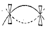
굴곡모우드이 진동자에서는 주변부에서 유지하는 것이 일반적이다. 종래의 바이모르프형에서는 중립면에 금속박판을 샌드위치 감기 해서 보강하는 것이 보통이며, 유니모르프형(unimorph型)에서는 금속의 진동판에 압전판을 발라붙이는 것이 보통이다. 이들 바이모르프 진동자를 유지하는데는 금속판의 주변부를 틀 등에 고정시키는 이른바 "주변고정"의 유지방식(제1도)에 의한다. 굴곡모우드의 진도자를 유지하는데는 주변지지방식(제2도)쪽이 고효율이지만, 실제상 주변지지방식으로 유지하는 것은 곤란하기 때문에 금속판을 압전판보다 크게 해놓고, 그 주변부를 고정하므로, 에너지의 변환효율은 이론치보다도 더욱 낮아진다.It is common for the flexor mode to remain at the perimeter of the oscillator. In the conventional bimorph type, it is common to sandwich and reinforce a metal thin plate on a neutral surface, and in a unimorph type, it is common to apply a piezoelectric plate to a metal diaphragm. The bimorph oscillator is held by a so-called "peripheral fixation" holding method (FIG. 1) which fixes the periphery of the metal plate to a frame or the like. Peripheral support method (Figure 2) is more efficient to maintain the guiding force of the curved mode, but it is difficult to maintain the peripheral support method in practice. Therefore, the metal plate is made larger than the piezoelectric plate and the periphery is fixed. The efficiency is even lower than the theoretical value.
한편, 본원 발명의 트랜스듀우서는 압전 진동자가 한단계 작은 틀속에 만곡상태로 유지되어 있으므로 제3도에 나타낸 것처럼 본질적으로 주변지지의 유지방식이 채택되어 있고, 이론치에 가까운 변환효율이 얻어지기 쉬운 구조로 되어 있는 것도 커다란 특징의 하나이다.On the other hand, since the piezoelectric vibrator is kept curved in a small frame, the transduder of the present invention adopts a peripheral support method, as shown in FIG. 3, and is easy to obtain conversion efficiency close to the theoretical value. It is also one of the great features.
이처럼 본원 발명을 투명 평판 스피이커에 적용하면, 실용상 충분한 음성을 확보할 수 있으며 또한 명료하게 할 수 있다. 즉, 이 투명 평판스피이커는 다음과 같은 이점을 갖는다. (1) 진동체와 음성발생면판을 겸해서 갖춘 것이기 때문에 발생면판에 진동체를 발라 맞추는 일이 불필요해진다. 이 때문에 접착제에 의한 투명도의 저하를 저지할 수 있게 되었다. 또 접착제의 경시열화에 의한 수명의 단축이 발생하지 않게 되었다. (2) 보호커버를 일반적으로 트랜스듀우서에서 떼어서 독립해서 설치하게끔 되어 기계적 임피이던스를 낮게. 또한 저음특성을 양호하게 할 수 있게 되었다. (3) 스피이커로서는 물론이고, 마이크로폰으로서도 이용할 수 있게 되었다.By applying the present invention to a transparent flat panel speaker as described above, it is possible to secure a practically sufficient sound and to make it clear. That is, this transparent flat panel speaker has the following advantages. (1) Since both the vibrating body and the sound generating face plate are provided, it is unnecessary to apply the vibrating body to the generating face plate. For this reason, the fall of the transparency by an adhesive agent can be prevented. In addition, shortening of the life due to deterioration of the adhesive over time does not occur. (2) Generally, the protective cover is removed from the transduder so that it can be installed independently, thereby lowering the mechanical impedance. In addition, the bass characteristics can be improved. (3) As well as a speaker, it can also be used as a microphone.
이처럼, 투명한 스피이커에 획기적인 이점을 발휘할 수 있도록 되었다. 즉, 종래의 투명평판 발음체는 투명세라믹을 주체로 해서 이루어진 것이며, 구조는 종래의 바이모르프 버저를 광대역화(廣帶域化)한 것에 지나지 않았던 것에 반하여 더 한층 실용범위가 확대된 것이다.In this way, the transparent speaker can be a significant advantage. That is, the conventional transparent flat sounding body mainly consists of a transparent ceramic, and the structure is a thing which only widened the conventional bimorph buzzer, but expands the practical range further.
제4a도~제4e도 및 제5a도~제5c도는 각기 압전 세라믹판의 각종 유지방법 및 이것에 대한 음성의 주파수특성의 경향을 모식적(模式的)으로 나타낸다.4A to 4E and 5A to 5C respectively show various holding methods of piezoelectric ceramic plates and trends in the frequency characteristics of the voices.
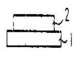
제4a도는 면판(1)상에 압전진동자(2)를 접착시킨 것이다. 그리고 압전진동자(2)에는 양 주면에 전극을 가지지만 도면에는 생략되어 있다. 이 경우, 압전진동자(2)와 함께 면판(1)도 진동하여 음을 내지만 음성 볼륨의 주파수밴드는 제5a도에 예시한 바와 같이 좁은 것이다. 또 음성볼륨도 작다. 이와 같은 구조는 일반적으로 버저에 사용되고 있는데 불과하며, 육성 등 음성의 발음은 어렵다.4A shows the
제4b도는 제4a도의 트랜듀우서를 개구부(8)를 갖는 틀(3)에 부착한 것이다. 틀(3)과 면판(1)의 접촉부분을 매듭으로 하여 면판(1)이 진동하므로 음성볼륨은 커지지만, 주파수밴드는 상술한 예와 비교해서 변화하지 않는다.4b attaches the transducer of FIG. 4a to the frame 3 with the opening 8. Since the
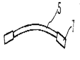
제4c도는 만곡형의 압전세라믹 면판(5)을 금속틀(4)의 첨단부에서 감합시킨 것이다. 면판(5)은 주연부가 금속과 같은 비탄성재료로 고정되어 있기 때문에 면판(5)은 면에 수직방향으로 매우 크게 진동한다.4C shows the curved piezoelectric ceramic face plate 5 fitted at the tip of the metal frame 4. Since the face plate 5 is fixed to an inelastic material such as metal, the face plate 5 vibrates very largely in the direction perpendicular to the face.
그러나 주파수밴드는 제5c도에 나타낸 바와 같이 매우 좁다.However, the frequency band is very narrow as shown in FIG. 5C.
제4d는 만곡형의 압전세라믹 면판(5)을 미소 변동 가능한 금속틀(6)에 감합시킨 것이다. 면판(5)과 함께 금속틀(6)도 미동하므로 주파수밴드는 제5e도에 나타낸 바와 같이 약간 커지지만, 음성을 발음시키기에는 불충분하다.4D is a fitting of the curved piezoceramic face plate 5 to the metal frame 6 which can be microvariably. Since the metal frame 6 is also finely moved together with the face plate 5, the frequency band is slightly larger as shown in FIG. 5E, but is insufficient to pronounce the voice.
제4e도는 본원 발명의 구성을 나타낸 것이다. 만곡형 압전 세라믹 면판(5)을 유기고분자 수지틀(7)에 감합시킨 것이다. (면판을 단부만으로 틀(7)에 접착착시켜도 좋다.) 동착시에 상기 면판(5)은 수직방향으로 진폭운동하는 동시에, 면의 수평방향으로도 굴신(屈伸)운동이 가능하다. 이것은 유기고분자수지의 강성률(剛性率)이 0.1×10⁵~0.5×10⁵Nm/kg(단, N은 뉴우톤 상수이다)이하이고 일반금속에 비해서 일반적으로 한자릿수 값이 작다. 즉 기계적인 힘에 대해 유언하며 면판의 유기적 기능도 갖추면서, 신축성이 풍부하다. 제5e도는 주파수밴드를 나타내고 있다. 0.1~5KHz에 걸쳐서 평탄한 주파수밴드가 얻어지며, 음성의 발음에 충분했었다.Figure 4e shows the configuration of the present invention. The curved piezoelectric ceramic face plate 5 is fitted to the organic polymer resin frame 7. (The face plate may be adhesively bonded to the frame 7 only by the end portion.) At the time of fixing, the face plate 5 is capable of amplitude movement in the vertical direction and flexion movement in the horizontal direction of the face. The organic polymer resin has a stiffness of 0.1 × 10 5 to 0.5 × 10 5 Nm / kg or less (where N is Newton's constant) and generally has a single digit value compared to a general metal. In other words, they testify about mechanical strength and have the organic function of the faceplate, and they are rich in elasticity. 5e shows a frequency band. A flat frequency band was obtained over 0.1-5KHz, which was sufficient for speech pronunciation.
[실시예 1]Example 1
제6a도 및 제6b도는 각기 본원 발명의 일실시예로서의 트랜스듀우서의 개략평면도 및 그 단면도이다.6A and 6B are schematic plan views and cross-sectional views, respectively, of a transduder as an embodiment of the present invention.
Pb(ZrTi)O3계 투명압전 세라믹으로 이루어진 직경 27㎜, 두께 0.2㎜의 압전원판을 준비한다. 이 투명압전 세라믹 원판(11)의 양 주면에는 투명전극(12)이 코우팅되어 있으며, 이 전극을 사용하여 직류고전압을 인가하는 분극처리가 실시되어 있다. 일변이 150㎜의 정방형이며 두께가 1.5㎜의 폴리카아보네이트의 투명판(15)을 준비하고, 이것의 중심부에 직경 26.95㎜의 구멍(14)을 뚫고, 그 구멍(14)속에 투명 세라믹 원판(11)을 끼워넣어, 곡경반경(曲徑半徑) R이 200~150㎜가 되는 만곡면 상태로 유지한다.A piezoelectric power plate having a diameter of 27 mm and a thickness of 0.2 mm made of Pb (ZrTi) O 3 -based transparent piezoelectric ceramic was prepared. The transparent electrodes 12 are coated on both main surfaces of the transparent piezoelectric ceramic original plate 11, and polarization treatment for applying a DC high voltage is performed by using the electrodes. A 150 mm square, 1.5 mm thick polycarbonate
폴리카아보네이트의 정방판(正方板)의 표리 양면에는 대각선에 연해서 투명막(16), (17)이 리이드선 대신에 코우팅되어 있고, 각기 단자(18), (19)에 접속되어 있다. 이 투명 리이드선(16), (17)의 구멍(14)에 대한 단부에 은페이스트(13)를 칠해서 투명압전판(11)의 전극(12)을 전기적으로 결합한다. 이와같이 해서 만들어진 트랜스듀우서는 단자(18), (19)에 오디오신호를 인가하면 스피이커로서 풍부한 음량을 방사할 수 있다.
본 실시예의 장점은 투명한 평판 스피이커를 실현시킨 점에 있지만, 또 하나의 장점은 발음부의 진동자의 기능에 있다. 즉, 폴리카아보네이트의 유지판(15)은 진동판(11)을 만곡상태로 유지하고 있는 관계상, 구멍(14)의 주변은 상당한 압축력으로 변형되어 있다. 이 때문에 진동판(11)이 진동해서 만곡변형되면 그 반작용으로서 유지판(15)도 진동하며, 유지판의 면으로도 음이 나온다. 이것이 본 실시예의 장점이며, 진동판(11)으로부터는 고주파성분의 음이 발생하여, 유지판(15)부분에서는 저주파성분의 음이 발생한다. 스피이커의 기능으로서 말하자면 진동판(11)부분은 고음확성기로서 작용하며, 유지판(15)의 부분은 저음확성기로서의 기능을 발휘한다. 그 결과, 출력의 주파수응답이 광대역이며, 50Hz에서 10KHz 이상에 걸치는 것이 확인되었다. 이것은 평판스피이커로서는 할 수 없었던 좋은 결과이다.An advantage of this embodiment is that the transparent flat panel speaker is realized, but another advantage lies in the function of the vibrator of the sounding unit. That is, since the holding
이상의 예에서는 유지를(15)로서 폴리카아보네이트를 사용했지만, 이것에 한정되는 것은 아니며 다른 유기고분자, 수지도 사용할 수 있다. 예를 들어 아크릴 또는 포오밍 폴리스티롤 같은 포오밍 레진, 하아드 비닐 크롤라이드, 페놀-호옹 알데히드 레진등 광범위한 재료를 사용할 수 있다. 또한 포스포르 브론즈, 스테인레스 스티일, 듀랄루민 등도 사용할 수 있었다.In the above example, although polycarbonate was used as fats and
이상의 실시예는 트랜스듀우서 단체에 관한 것이지만, 용도와의 관계로 특징적인 경우에 대해서도 언급해 둔다.Although the above embodiment relates to a transducer unit, reference is also made to the characteristic case in relation to the use.
[실시예 2]Example 2
제7도는 본원 발명의 또 다른 실시에로의 트랜스듀우서의 개략단면도이다.7 is a schematic cross-sectional view of a transduder to another embodiment of the present invention.
실시예 1에 사용한 것과 같은 진동자(21)를 실시예 1과 같은 질의 폴리카아보네이트에 장착하지만, 본 실시에에서는 폴리카아보네이트는 판이 아니며, 제7도에 나타낸 바와같이 외경 33㎜![]()
![]()
![]()
![]()
[실시예 3]Example 3
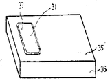
제8도는 본원 발명의 또 다른 실시예로서의 트랜스듀우서의 개략사시도이다.8 is a schematic perspective view of a transduder as another embodiment of the present invention.
Pb(ZrTi)O3계 투명 세라믹판을 20㎜×40㎜의 크리고 두께 0.2㎜의 구형판(31)에 성형하고, 투명 전극을 코오팅하여, 분극해서 압전판으로 한다. 이것을 200~150㎜의 극률반경을 이루는 곡면으로 만곡시키고, 100㎜×70㎜이며, 1.5㎜두께의 폴리 카아보네이트판(35)에 끼워 넣어 유지한다. 별도로 준비한 폴리 가아보네이트제의 100㎜×70㎜×15㎜ 크기의 상자(36)에 상술한 폴리카아보네이트판(35)을 뚜껑을 덮는 형태로 씌워서 고정시킨다. 이 상자 내부에는 라디오, 테이프레코오더 등의 오디오기기를 수용할 수 있고, 그 입력을 투명전극에 인가하면, 진동자(31)는 스피어커로서 동작하지만, 상자(36)가 공명(共鳴)상자로서 작용하기 때문에 상당히 큰 음량이 얻어졌다A Pb (ZrTi) O 3 -based transparent ceramic plate is molded into a
[실시예 4]Example 4
제7도는 본원 발명의 또 다른 실시예로서의 트랜스듀우서의 개략사시도이다.7 is a schematic perspective view of a transduder as another embodiment of the present invention.
직경 40㎜![]()
![]()
![]()
![]()
이것으로 개공간용(開公間用)트랜스듀우서가 만들어진 것이며 헤드폰, 전화의 송수화기 등의 케이스에 넣어, 단자(47) 및 (48)을 소정의 회로와 접속하면 각각의 용도에 적합한 트랜스듀우서로 된다. 헤드폰, 수화기 등에 사용했을 경우에는 트랜스듀우서 케이스의 개구가 귀로 막히므로, 진동자는 음향 임피이던스의 정합(整合)을 취하기 쉬워지며, 감도, 음질이 모두 양호해진다. 헤드폰으로서 사용했을 경우는 1.5볼트의 신호가 인가되면 귀에 충분할 만큼의 음이 들린다. 송화기로서 사용할 경우는 반개공간(半開空間)상태로 되어, 감도가 높아지는 동시에 외부 잡음으로부터 보호된다. 단 트랜스듀우서는 케이스로부터 충분히 제진(除震)해서 수납해야 한다.This is a transducer for open spaces, which is placed in a case such as a headphone or a handset of a telephone, and when the
이상 본원 발명의 트랜스듀우서를 실시예에 의거하여 설명했지만, 송화기나 수화기에도 사용할 수 있고, 초박형으로 구성할 수 있으며, 구조가 간단하고 전기/음향 변환효율이 높다는 등의 기본적 장점이 있다.Although the transduder of the present invention has been described above based on the examples, it can be used in a transmitter or receiver and can be configured to be ultra-thin, and there are basic advantages such as simple structure and high electric / acoustic conversion efficiency.
[실시예 5]Example 5
이 종류의 트랜스듀우서의 요건은 압전 세라믹 박판을 만곡면상으로 유지하는 일이다. 만곡면은 구면상(球面狀)의 형으로서 세라믹판을 끼고 실온 또는 고온으로 프레스한 후, 접착제에 의해 고정시켜서 세라믹에 만곡변형을 남기는 방법 등 주지의 기술을 응용 또는 조합(組合)해서 적용시킬 수 있다. 이때, 세라믹판의 형상은 원, 타원, 정방형, 구형, 다각형 등 임의의 형상으로 좋다. 만곡변형한 압전 세라믹의 표리(表裏)양 주면의 전극에 리이드선을 접속하고 오디오 전기신호를 인가한다. 압전 세라믹 평판을 만곡 변형시킨 것만으로 이 세라믹판의 주위가 상기 접착제에 의해 고정될 수 있으므로, 면에 수직방향의 진동운동이 발생해서 오디오트랜스듀우서로 할 수 있었다.The requirement of this kind of transduder is to keep the piezoelectric ceramic thin plates on a curved surface. The curved surface is a spherical shape, which is pressed by using a ceramic plate at room temperature or high temperature, and then fixed with an adhesive to leave a curved strain on the ceramic. Can be. At this time, the shape of the ceramic plate may be any shape such as circle, ellipse, square, sphere, polygon. Lead wires are connected to electrodes on both front and back surfaces of the curved piezoelectric ceramic, and an audio electric signal is applied. Since only the curvature of the piezoelectric ceramic plate can be fixed, the periphery of the ceramic plate can be fixed by the adhesive, so that a vibrational movement in the vertical direction occurs on the surface, thereby making it an audio transducer.
상기, 만곡변형된 압전 세라믹 트랜스듀우서를 그 외형과 대충 상사(相似)한 현상이며 크기가 조금 작은 구멍이 뚫린 틀에 고정시키는 것이 중요하다. 개구공의 크기가 세라믹보다 조금 작으므로 세라믹의 주변은 한결같은 구멍에서 삐져 나온 상태로 틀에 올려 놓을 수 있다. 이 때문에 용이하게 세라믹판의 주변을 틀과 접착제로 고정시킬 수 있는 이점이 있다. 이 방법으로 만들어진 세라믹은틀에 고정되었기 때문에, 만곡변형을 항상 안정되게 영구 유지할 수 있고, 더구나 오디오신호가 인가되었을 때 세라믹의 외경은 틀의 공경(孔徑)으로 변화하기 어렵게 억압되어 있기 때문에 그만큰 주변이 자유로운 만곡판에 비해서, 보다 크게 굴곡진동이 발생하는 결과, 트랜스듀우서의 방사음량이 증대한다.It is important to fix the curved deformed piezoelectric ceramic transducer to a mold having a slightly smaller size and having a shape that is roughly similar to its appearance. Since the opening is slightly smaller than the ceramic, the periphery of the ceramic can be placed in the mold with the same hole protruding from it. For this reason, there is an advantage that can easily fix the periphery of the ceramic plate with a mold and an adhesive. Since the ceramic made by this method is fixed to the mold, the curved deformation can be kept stable and permanently at all times. Moreover, when the audio signal is applied, the outer diameter of the ceramic is hardly changed to the pore diameter of the mold, which is great. As a result of the greater bending vibration than the freely curved curved plate, the radiation volume of the transducer increases.
이와 같은 일은 스피이커에 한정되지 않으며 음을 전기신호로 변환하는 마이크로폰으로서 트랜스듀우서를 사용할 경우에도 마찬가지이다. 따라서 이하, 트랜스듀우서의 설명은 간단을 기해 주로 스피이커를 대상으로 하여 기술한다.This is not limited to loudspeakers, even if you use a transducer as a microphone to convert sound into an electrical signal. Therefore, hereinafter, the description of the transducer will be described mainly for the speaker for simplicity.
세로믹판에 오디오신호가 인가되고, 판이 신축하는 동시에 외주(外周)도 변화하려고 하지만 상술한 바와 같이 틀에 고정되어 있다. 틀판의 크기를 세라믹보다 충분히 크게 선택하면, 틀판은 저주파의 신호에 대해서 충분히 양호한 응답이 얻어진다. 즉 면적이 충분히 큰 틀판으로 만곡변형한 압전세라믹판을 고정시키면, 저음응답성이 좋은 트랜스듀우서를 구성할 수 있어서 음질이 개선된다. 즉, 유지판은 기계적으로 충분히 세라믹판을 유지할 수 있는 동시에, 음성 특성을 양호하게 하기 위해서 충분히 크게 하면 더욱 좋다.An audio signal is applied to the vertical mixing plate, and the plate expands and contracts, and the outer periphery is also changed, but is fixed to the frame as described above. If the size of the template is selected sufficiently larger than that of the ceramic, the template has a sufficiently good response to low frequency signals. In other words, if the curved piezoelectric ceramic plate is fixed to a mold plate with a sufficiently large area, a transduder having a low sound response can be formed, thereby improving sound quality. In other words, the holding plate may be mechanically sufficiently sufficiently held, while the holding plate may be made large enough to improve sound characteristics.
여기서, 세라믹평판을 만곡시켜 고정도(高精度)로 잔류변형을 만드는 것은 간단한 일이 아니다. 그렇다고 하는 것은 정도가 높은 지그(Jig)를 필요로 하며, 변형의 곡률반경이 크면 변형이 남지 않으며, 곡률반경이 작으면 변형은 되기 쉬어지지만 깨어지기 쉽다. 더구나 곡률반경이 지나치게 작아 당장에라도 깨질 정도로 멋지게 변형되어 있는 것보다는 곡률반경이 커서 가까스로 만곡하고 있는 것을 알 수 있을 정도로 안정된형상을 유지하는 트랜스듀우서쪽이 전기음향 변화효율이 높다. 이 때문에 상기 세라믹박판은 약간, 그리고 확실하게 변형시켜 놓는 것이 바람직하다.Here, it is not a simple matter of bending the ceramic plate to make residual strain with high accuracy. That is, it requires a high degree of jig. If the radius of curvature of the deformation is large, no deformation is left. If the radius of curvature is small, the deformation is easy to be broken, but is easily broken. Moreover, rather than being too deformed to break even if the radius of curvature is too small, the transduer side, which maintains a stable shape so that the curvature radius is barely curved, has high electro-acoustic change efficiency. For this reason, it is preferable to deform the ceramic thin plate slightly and surely.
이것을 실현하기 위한 구체적수단으로서, 예를 들어 세라믹의 외형보다 약간 작은 크기의 구멍이 뚫린 틀판을, 구상의 철면대(凸面台)위에 올려놓고. 틀판의 위에서부터도 철면의 맞는 요면(凹面)을 갖는 무거운 링을 종(鍾)으로서 올려놓는다. 틀판은 철면상으로 변형하며 구멍의 사이즈는 확대된다. 이 확대된 상태에서 구멍 주변의 상면과 세라믹의 하면을 접착한다. 접착제가 경화하면 틀을 철면대에서 조용히 벗기고, 휜것을 고쳐서 평면으로 하면, 세라믹판이 접착면을 안으로 해서 용이하게 철면 변형이 얻어진다. 다음에 구체적으로 설명한다.As a specific means for realizing this, for example, a frame plate with a hole slightly smaller than the appearance of ceramics is placed on a spherical steel stand. A heavy ring having a concave concave surface of the iron surface is also placed as a bell from above the frame. The frame is deformed into the steel surface and the size of the hole is enlarged. In this enlarged state, the upper surface around the hole and the lower surface of the ceramic are bonded. When the adhesive is cured, the mold is peeled off from the iron stand quietly, and the flattening is made flat, so that the ceramic sheet is brought into the adhesive surface and the iron sheet deformation is easily obtained. It demonstrates concretely next.
철면상 압전세라믹 트랜스듀우서는 Pb(ZrTi)O3계 세라믹으로 대표되는 압전세라믹 또는 Pb1-xLax(Zr1-yTiy)1- T1 O3로 대표되는 투명압전 세라믹(51)을 소재로 하여, 두께 0.1~0.5㎜정도, 면적 200~10,000㎟ 정도이고 두께에 대한 면적의 비율이 2,000~20.000㎜ 정도의 엷고 편편한 세라믹 박판을 만든다. 제10도에 평면도를 나타낸다. 박판의 형상은 목적에 응해서 원, 타형, 정방형, 구형, 다각형 등 임의이다, 이를 박판(51)의 양 주면에 은(銀)가 열압착, 금속증착, 스퍼터, 도금, 스프레이, 도포 등의 방법으로 전극(52)을 부착시킨다. 전극은 목적에 응해서, 은 가열압착과 같은 윤택이 없는 상태, 도금막처럼 금속광태을 한 상태 또는 In2O3-SnO2의 투명전 극막 등 여러 가지 적용이 가능하지만, 본원 발명의 트랜듀스우서에는 엷은 전극만이 단단하게 부착되어 있을 것이 바람직하며, 더구나 직접 리이드선(54), (54')를 납땜할 수 있는 부분(55)을 갖는 편이 편리하다.The piezoelectric ceramic transducer on the steel plate uses a piezoelectric ceramic represented by Pb (ZrTi) O 3 based ceramic or a transparent piezoelectric ceramic 51 represented by Pb 1-x Lax (Zr 1-y Ti y ) 1 -T1 O 3 . As a raw material, a thin and flat ceramic thin plate having a thickness of about 0.1 to 0.5 mm, an area of about 200 to 10,000
이이서, 상기 표리 두판의 전극사이에 직류고전압을 인가해서 분극처리를 한다. 이 분극처리에 의해서 압전성이 생기지만 처리조건은 소재마다 특유한 것으로, 고유의 최적(最適)조건에 따르면 되지만, 일반적으로는 80℃정도의 고온분위기(절연유를 사용하는 일도 있음)중에서 20~40KV/㎝정도의 직류고전압을 30분 이상 인가한다. 분극된 압전세라믹 평판은 소정의 유지판에 접착 고정되어서 구면상으로 만곡변형이 주어져서 트랜듀우서가 얻어진다.Next, a polarization treatment is performed by applying a direct current high voltage between the electrodes of the front and back plates. Although the piezoelectricity is generated by this polarization treatment, the processing conditions are unique to each material, and according to the inherent optimum conditions, generally, 20 to 40 KV / in a high-temperature atmosphere (sometimes using insulating oil) of about 80 ° C. Apply a DC high voltage of 30 cm or more. The polarized piezoceramic flat plate is adhesively fixed to a predetermined holding plate to give a curved deformation on a spherical surface to obtain a transducer.
만곡면의 다른 형성방법을 다음에 설명한다.Another method of forming the curved surface will be described next.
제11도에 나타낸 바와 같이, 상기 분극된 압전세라믹 박판(61)을 곡률반경 약 400㎜의 철면상의 구형지그(65)와 같은 곡률로 요면상의 지그(66)사이에 끼우고, 철면판상의 변형을 준다. 그리고(62)는 압전세라믹판에 설치된 전극, (67)(67')는 배선이다. 여기서 곡률반경이 크면 변형이 남지 않으며, 반경이 작으면 세라믹이 깨지기 쉽다. 안정된 변형을 얻기 위해, 고온에서 프레스를 하면 효과적이다. 이 경우, 사용하는 세라믹판을 상술한 방법으로 전극을 형성하고, 분극 전의 것을 사용한다. 분극후의 것은 고온 프레스하면 분극이 해소되어 재분극을 요한다.As shown in FIG. 11, the polarized piezoceramic
상술한 바와 같은 구면상의 지그를 스테인레스 스티일을 사용하여 만들고, 전극이 달린 세라믹판을 끼워넣어 소재의 퀴리(curie)온도 이상으로 가열했다. 소재를 퀴리온도 이상으로 잠시 유지한 다음 서서히 냉각한다. 소재의 온도가 100℃보다도 낮아졌을 때, 전극사이에 20~40KV/㎝ 정도의 강도의 직류전장(電場)을 인가하면서 서서히 냉각하면 만곡변형을 만드는 것과 동시에 분극처리를 할 수 있었다.The spherical jig as mentioned above was made using stainless steel, and the ceramic plate with an electrode was sandwiched and heated above the Curie temperature of a raw material. Hold the material briefly above the Curie temperature and allow it to cool slowly. When the temperature of the material was lower than 100 ° C., when it was gradually cooled while applying a DC electric field having a strength of about 20 to 40 KV / cm between the electrodes, the curvature deformation and polarization treatment could be performed.
[실시예 6]Example 6
전왜효과(電歪效果)가 큰 세라믹을 이용해도 똑같은 효과가 얻어진다. 다음에 제14도에 의거하여 예시한다.The same effect can be obtained by using a ceramic having a large warping effect. Next, it demonstrates based on FIG.
여기서 사용한 것은 Pb(Mg1/3 Nb2/3)O3-PbTiO3계 세라믹이며, 형성은 실시예 5의 소자와 마찬가지이며, 전극(62)도 마찬가지로 실시하여 두께 0.1㎜, 직경 30㎜![]()
![]()
트랜스듀우서에 음이 인가되면, 철면의 곡률이 음의 진폭에 응해서 변화하므로, 트랜스듀우서를 만곡시키고 있는 장력이 변화하며, 이것에 응해서 트랜스듀우서의 전기용량이 변화한다. 즉 등가회로적으로 설명하면 전원에서 바이어스전압이 인가된 콘덴서의 용량의 음의 진동에 응해서 변화하므로 부하저항(71)을 지나서 전류가 흐른다. 저항(71)의 전압강하에 의한 전원차를 증폭하면, 음향신호에 응한 전기적출력이 얻어지며, 고감도, 고품위의 마이크로폰으로서 쓸모가 있다는 것이 실증되었다.When sound is applied to the transducer, the curvature of the iron surface changes in response to the amplitude of the sound, so that the tension bending the transducer is changed, and the capacitance of the transducer is changed accordingly. In other words, in an equivalent circuit, since the power supply changes in response to the negative vibration of the capacitor of the capacitor to which the bias voltage is applied, a current flows through the load resistor 71. By amplifying the power supply difference caused by the voltage drop of the resistor 71, it was proved that an electrical output was obtained in response to an acoustic signal, and was useful as a high-sensitivity, high-quality microphone.
전원을 직류전원에서 100KHz 이상의 교류신호의 정전압전원과 바꾸면, 음성으로 변조된 출력이 얻어지며, 오디오신호성분을 검파하면 직류전원의 경우보다 더욱 찌그러짐이 적은 고품위의 출력이 얻어졌다.When the power supply was changed from the DC power supply to the constant voltage power supply of the AC signal of 100 KHz or more, a voice modulated output was obtained. When the audio signal component was detected, a high quality output with less distortion was obtained than the DC power supply.
[실시예 7]Example 7
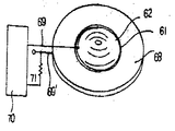
실시예 6과 같은 방법으로 만든 Pb(Mg1/3 Nb2/3)O3PbTiO3게 세라믹을 사용한 전왜 트랜스듀우서(61)를 역시 직경 50㎜, 내경 25㎜, 두께 1.5㎜의 도우너트형 폴리카아보네이트 링(68)에 접착함으로써, 철면상으로 변형시켰다. 전왜 세라믹의 표면은 경면연마(鏡面硏磨)되고, 그 위에 알루미늄이 증착되며, 거울과 전극을 겸하고 있다. 전극에 리이드선(72) 및 (73)을 본 딩해서 제15도에 나타낸 전압가변초점경을 작성했다.A
트랜스듀우서 안쪽에 레이저의 평행광속(74)을 조사하면, 레이저광은 트랜스듀우서의 전방 약 400㎜의 위치(75)에 초점이 맞았다. 이 상태에서 리이드선(72)과 (73)에 직류 전압을 인가한 100볼트 인가했더니 초점거리는 약 150㎜까지 짧아졌다. 전압의 크기에 대한 초점거리의 변화는 직선적이 아니며, 2차 곡선적이기는 하지만, 인가전압의 값과 초점거리의 관계가 일의적(一義的)으로 정해지는 이 장점이다. 전압을 승압시키면서 측정한 값의 구성과 강압하면서 측정한 구성은 자주 일치하고 있으며, 히스테리시스현상은 볼 수 없었다. 인간전압의 안정성을 충분히 확보하면 초점거리의 변화는 매우 정확하게 제이할 수 있다는 것이 판명되었다.When the parallel beam of light 74 of the laser was irradiated inside the transducer, the laser beam focused at a
본원 발명에 의하면 세라믹 트랜스듀우서의 외형을 임의로 선택할 수 있으므로 원하는 진동모드를 선택할 수 있는 효과가 있으며, 트랜스듀우서를 고정시킬 틀의 고정부의 형상도, 트랜스듀우서의 외향과정확하게 상사형(相似形)으로 하지 않아도 되므로, 고정도의 가공을 필요로 하지 않으며, 낮은 원가로 양산이 가능하다고 하는 효과가 있다. 또한 본원 발명에 의하면 세라믹 트랜스듀우서의 변형은 틀체에 의해 완전히 구속되어 있는 것이 아니고 틀과의 힘의 균형으로 형상이 유지되고 있기 때문에 스트랜스듀우가 진동하는 것과 동시에 틀에도 진동을 유발할 수 있는 장점을 가지므로 진동의 음역이 확대되고, 음량도 증대되는 효과가 있다. 특히 대면적의 틀판에 고정해서 음역, 음량을 개선할 수 있는 효과가 있다.According to the present invention, since the external shape of the ceramic transducer can be arbitrarily selected, the desired vibration mode can be selected, and the shape of the frame of the frame to which the transducer is fixed is also similar to the outward process of the transducer. Since it does not have to be shaped, it does not require high-precision machining and has the effect that mass production is possible at low cost. In addition, according to the present invention, since the deformation of the ceramic transducer is not completely constrained by the frame, but the shape is maintained by the balance of the force with the frame, the transducer may vibrate and cause vibration in the frame. Since the range of vibration is enlarged, the volume is also increased effect. In particular, it is effective to improve the range and volume by fixing on the large plate.
Claims (3)
Applications Claiming Priority (3)
| Application Number | Priority Date | Filing Date | Title |
|---|---|---|---|
| JP80-155906 | 1980-11-07 | ||
| JP55155906A JPS5780898A (en) | 1980-11-07 | 1980-11-07 | Piezoelectric ceramic transducer |
| JP55-155906 | 1980-11-07 |
Publications (2)
| Publication Number | Publication Date |
|---|---|
| KR830008624A KR830008624A (en) | 1983-12-10 |
| KR880000403B1 true KR880000403B1 (en) | 1988-03-21 |
Family
ID=15616094
Family Applications (1)
| Application Number | Title | Priority Date | Filing Date |
|---|---|---|---|
| KR1019810004221A KR880000403B1 (en) | 1980-11-07 | 1981-11-04 | Piezoelectric ceramic transducer |
Country Status (2)
| Country | Link |
|---|---|
| JP (1) | JPS5780898A (en) |
| KR (1) | KR880000403B1 (en) |
Families Citing this family (5)
| Publication number | Priority date | Publication date | Assignee | Title |
|---|---|---|---|---|
| JPS6232699U (en) * | 1985-08-09 | 1987-02-26 | ||
| JPH0518791U (en) * | 1991-08-26 | 1993-03-09 | 株式会社ジヨーニシ | Empty can processor |
| EP1136188B1 (en) | 2000-03-16 | 2007-05-16 | Makita Corporation | Power impact tools with impact sound detecting means |
| WO2002021881A1 (en) * | 2000-09-04 | 2002-03-14 | Applied Electronics Laboratories, Inc. | Display window having voice input/output function |
| JP4149444B2 (en) * | 2005-01-12 | 2008-09-10 | 富士通メディアデバイス株式会社 | Piezoelectric thin film resonator and filter using the same |
Family Cites Families (1)
| Publication number | Priority date | Publication date | Assignee | Title |
|---|---|---|---|---|
| JPS5214073B2 (en) * | 1972-09-01 | 1977-04-19 |
-
1980
- 1980-11-07 JP JP55155906A patent/JPS5780898A/en active Granted
-
1981
- 1981-11-04 KR KR1019810004221A patent/KR880000403B1/en active
Also Published As
| Publication number | Publication date |
|---|---|
| JPS5780898A (en) | 1982-05-20 |
| JPH0136315B2 (en) | 1989-07-31 |
| KR830008624A (en) | 1983-12-10 |
Similar Documents
| Publication | Publication Date | Title |
|---|---|---|
| US4471258A (en) | Piezoelectric ceramic transducer | |
| KR101731875B1 (en) | Electro-acoustic transducer | |
| US5802195A (en) | High displacement solid state ferroelectric loudspeaker | |
| US4430529A (en) | Piezoelectric loudspeaker | |
| CN103004236B (en) | Audio frequency apparatus and oscillating unit | |
| JP5741580B2 (en) | Oscillator | |
| JPS6132879B2 (en) | ||
| WO2013145739A1 (en) | Electronic apparatus and panel unit | |
| JP5949557B2 (en) | Electronics | |
| US5570428A (en) | Transducer assembly | |
| US4449019A (en) | Piezoelectric loudspeaker | |
| CN101765046A (en) | Nonmetallic vibration film multilayer piezoelectric speaker | |
| CN103262576A (en) | Oscillator device and electronic instrument | |
| CN103270776B (en) | Oscillation device and electronic equipment | |
| KR880000403B1 (en) | Piezoelectric ceramic transducer | |
| JPH09135496A (en) | Piezoelectric electric acoustic device | |
| CN203896502U (en) | Piezoelectric loudspeaker | |
| JP3202169B2 (en) | Piezoelectric sounding body | |
| JPS58166900A (en) | Piezoelectric sound generator | |
| JP2004096225A (en) | Piezoelectric sound generating device | |
| CN201608894U (en) | Multilayer piezoelectric speaker adopting non-metallic vibrating diaphragm | |
| CN220383495U (en) | Piezoelectric ceramic fiber composite structure and vibration device | |
| JP3246685B2 (en) | Electroacoustic transducer | |
| JPS5983498A (en) | Electroacoustic transducer | |
| JPH1056689A (en) | Piezoelectric sounding body |