KR870001727B1 - Upper fabric feed for a sewing machine - Google Patents
Upper fabric feed for a sewing machine Download PDFInfo
- Publication number
- KR870001727B1 KR870001727B1 KR1019810004421A KR810004421A KR870001727B1 KR 870001727 B1 KR870001727 B1 KR 870001727B1 KR 1019810004421 A KR1019810004421 A KR 1019810004421A KR 810004421 A KR810004421 A KR 810004421A KR 870001727 B1 KR870001727 B1 KR 870001727B1
- Authority
- KR
- South Korea
- Prior art keywords
- foot
- propulsion
- sewing machine
- fabric
- plate
- Prior art date
Links
Images


Classifications
-
- D—TEXTILES; PAPER
- D05—SEWING; EMBROIDERING; TUFTING
- D05B—SEWING
- D05B27/00—Work-feeding means
- D05B27/02—Work-feeding means with feed dogs having horizontal and vertical movements
- D05B27/04—Work-feeding means with feed dogs having horizontal and vertical movements arranged above the workpieces
-
- D—TEXTILES; PAPER
- D05—SEWING; EMBROIDERING; TUFTING
- D05B—SEWING
- D05B27/00—Work-feeding means
Landscapes
- Engineering & Computer Science (AREA)
- Textile Engineering (AREA)
- Sewing Machines And Sewing (AREA)
Abstract
Description
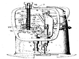
제1도는 본 발명에 의한 추진장치를 가진재봉기를 보여주는 측면도.1 is a side view showing a sewing machine having a propulsion device according to the present invention.
제2도는 제1도에 의한 장치의 작동을 보여주는 구조도(발(1)이 상부로 올라가 있는 상태).2 is a structural diagram showing the operation of the device according to FIG. 1 (with the foot 1 raised).
제3도는 제2도에서 발(1)과 발(3)의 높이가 일치하였을 때의 상태를 보여주는 구조도.3 is a structural diagram showing the state when the height of the foot (1) and foot (3) in FIG.
제4도는 발(3)이 상부로 올라가 있을때의 상태를 보여주는 구조도.4 is a structural diagram showing a state when the foot (3) is raised to the top.
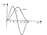
제5도와 제6도는 종래의 원단 추진장치의 작동을 보여주는 도표.5 and 6 are diagrams showing the operation of a conventional far-end propulsion device.
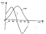
제7도는 본 발명에 의한 장치의 작동을 보여주는 도표.7 is a diagram showing the operation of the device according to the invention.
* 도면의 주요부분에 대한 부호의 설명* Explanation of symbols for main parts of the drawings
1 : 추진발 2, 4 : 샤프트1:
3 : 고정발 5 : 스리브3: fixed foot 5: sleeve
6 : 축 7 : 몸체6: axis 7: body
9 : 부싱 12 : 삼각링크9
15 : 스프링 16 : 스리브15: spring 16: sleeve
17 : 회전판 21 : 벨크랭크17: rotating plate 21: Bell Crank
25 : 활판봉25: letterpress
본 발명은 기능을 달리하는 두개의 별개의 발(foot)을 갖는 원단 추진방법 및 추진장치를 가진 재봉기에 관한 것이다.The present invention relates to a fabric pushing method having two separate feet with different functions and a sewing machine having a pushing device.
미국특허 제4,116,145호와 제3,196,815호에서 이미 봉제원단을 재봉판에 고정시켜 주는 역활을 하는 발과 원단을 밀어주는 작용을 하는 별개의 발을 갖는 재봉기가 이미 소개된바 있는데 이러한 재봉기에 있어서 원단을 밀어주는 발은 상하운동뿐 아니라(첨부된 도면상으로 볼 때) 좌우운동도 하게 되어 있다. 이 좌우운동을 하는 발은 재봉판내부에 설치된 "톱니"(도면에 보여지지 않고 있다)와 함께 원단을 밀어주는데 이 톱니도 좌우운동을 한다.U.S. Patent Nos. 4,116,145 and 3,196,815 have already introduced a sewing machine having a foot that acts to secure the sewing fabric to the sewing plate and a separate foot that acts to push the fabric. The pushing foot is supposed to not only move up and down (as shown on the accompanying drawings) but also to move left and right. This left and right movement foot pushes the fabric together with the "tooth" (not shown) installed inside the sewing plate, which also moves left and right.
첨부된 도면에 의하여 이미 발표된 상기 두 특허의 재봉기를 설명하면 제4도에서와 같이 추진발(1)이 내려져서 그 저부에 있는 톱니와 함께 원단을 물으면 고정발(3)은 위로 들리고 발(1)과 톱니는 원단을 물고 좌측으로 움직여서 원단을 일차 전진시키고 고정발(3)은 다시 내려와서 제3도와 같이 전진된 원단을 재봉판에 고정시켜 주고 추진발(1)은 위로 들리고 톱니는 아래로 내려져서 원단을 놓아주었다가 다시 원위치로 돌아와서 원단을 또 한번 물고 전진시켜 주는데 이러한 작동을 반복적으로 계속하여 비교적 고속에서도 원단이 뛰로 밀리지 않고 정확하게 재봉되어 나가게 한다. 상기 미국특허 제4,116,145호에 의하면 재봉기의 주구동축의 회전운동이 디스크(17)과 연결봉(18)을 통하여 벨크랭크(21)로 전달되고, 벨 크랭크(21)은 활판봉(25)을 좌우로 움직이게 하며, 활판봉(25)에 연결된 삼각 링크(12)는 상기한 두개의 발이 상하로 움직이게 하는데 삼각 링크(12)는 스프링(15)에 의하여 아래쪽으로 눌려진다.Referring to the sewing machine of the two patents already announced by the accompanying drawings, as shown in FIG. 4, when the propelling foot 1 is lowered and bites the fabric together with the teeth on the bottom, the
이때에 추진발(1)이 상하 운동을 하는 속도는 발이 원단에 접근함에 따라 즉 추진발(1)이 운동하는 최하 지점에 접근함에 따라 "싸인" 곡선과 같이(sinusoidally) 감소되어 최하지점에서는 0이 된다.At this time, the speed at which the propulsion foot 1 moves up and down decreases as a “signus” curve (sinusoidally) as the foot approaches the distal end, that is, as the propulsion foot 1 approaches the lowest point. Becomes
이와는 반대로 전기 미국특허 제3,196,815호의 재봉기에서는 추진발(1)의 속도가 발이 원단에 따라 가속되고, 추진발(1)이 최하 지점에 오면 추진발(1)의 속도는 최고로 빨라지고 이때에 원단은 심하게 진동된다. 이 추진발(1)의 접근 속도를 최대한으로 감소시켜 원단이 펄럭거리는 것을 막아주고, 원단이 펄럭거리는 것을 막는 댐퍼(damper)의 필요를 없이하여 주는 방법이 미국특허 제4,116,145호의 재봉기의 방법이다. 상기한 두 방법에서 삼각링크(12)는 스프링(15)에 의하여 아래로 눌려지는데 스프링(15)의 강도는 임의로 조종이 될 수 있어 스프링(15)을 약하게 조정하면 원단의 진동에 의하여 삼각링크가 심하게 진동하게 하고 스프링(15)를 강하게 조정하면 삼각링크(12)가 연결되어 있는 모든 축 즉 피벗에 무리가 가고 기계가 필요 이상으로 무겁게 돌게한다. 그리고 이 스프링(15)는 기계를 고속으로 작동시킬때 삼각링크(12) 및 여기에 연결된 부분에 가하여지는 탄력을 흡수하는 역활을 하게도 한다.On the contrary, in the sewing machine of U.S. Patent No. 3,196,815, the speed of the propulsion foot 1 is accelerated according to the fabric, and when the propulsion foot 1 is at the lowest point, the speed of the propulsion foot 1 becomes the highest and the fabric is severely deformed Vibrates. The method of the sewing machine of US Pat. No. 4,116,145 reduces the approach speed of the propulsion foot 1 to prevent the fabric from fluttering and eliminates the need for a damper to prevent the fabric from fluttering. In the above two methods, the
따라서 본 발명의 목적은 재봉기의 발을 더욱 개선하는데 있으며, 상기한 종래의 재봉기의 단점을 제거하는데 있고 고속으로 원단을 밀어주는 발을 고안하는데 있다.Therefore, an object of the present invention is to further improve the foot of the sewing machine, to eliminate the disadvantages of the conventional sewing machine and to devise a foot that pushes the fabric at high speed.
본 발명에서도 상기한 방법과 같이 서로 엇갈리게 상하운동을 하는 두개의 발을 이용하고 회전운동을 상하 운동으로 전환하는 구동장치도 상기한 방법에서와 거의 같으나 본 발명의 방법에 있어서는 두 개의 발이 각기 상하 운동을 하는 상단지점에서 하단 지점으로 내려올때 그 중간지점에 접근함에 따라 그 속도가 최대한으로 가속되고 중간지점을 지나서 하단으로 접근할 때에는 다시 감속되어 하단에서는 0에서 최대 속도의 7분의 1의 속도에 못미치는 중간속도가 되게 한다. 이러한 속도로 재봉기를 구동시키면 두꺼운 원단을 재봉할때는 원단 자체가 어느 정도의 진동은 흡수하여 원단이 펄럭거리지 않는 다는 것이 본 발명을 통하여 발견되었으며, 엷은 원단을 재봉할 때에는 어느 정도 원단이 펄럭거리거나 미국특허 제3,16,815호의 재봉기의 경우보다는 발이 내려오는 속도가 감소되었기 때문에 좀더 약한 스프링을 써도 괜찮은 이점을 얻는다. 그리고 미국특허 제4,116,145호의 방법의 취약점도 어느 정도 감소시켜 재봉기의 작동을 더울 빨리 할 수 있게 한다. 다시 말하면 빠른 속도로 내려와서 원단을 물어주는 방식에서 가져오는 기계에 가하여지는 충격이나 원단이 펄럭거리는 문제나 느린 속도(0의 속도)에서 원단을 물어주는 방법에 수반되는 능률 저하문제를 본 발명이 다 해소하여 준다. 예를들면, 종래의 방법에서는 재봉기의 분당 회전속도가 2000내지 3000회전(RPM)에 불과하였으나, 본 발명의 재봉기의 회전속도는 분당 5000회전(RPM)에 달한다.In the present invention, as in the above-described method, the driving device using two feet which cross each other in a vertical movement and the rotational movement to the vertical movement are also almost the same as in the above method, but in the method of the present invention, the two feet are each vertical movement When descending from the upper point to the lower point, the speed is accelerated to the maximum as it approaches the middle point, and decelerated again when approaching the lower end beyond the middle point. Try to reach a moderate speed. When the sewing machine is driven at this speed, the fabric itself absorbs a certain amount of vibration when sewing a thick fabric so that the fabric does not flutter, and when sewing a thin fabric, the fabric flutters to some extent or the United States. The speed of the foot descending is reduced compared to that of the sewing machine of Patent No. 3,16,815, so that a weaker spring may be used. In addition, the vulnerability of the method of US Patent No. 4,116,145 is also reduced to some extent to allow the operation of the sewing machine to be made faster and faster. In other words, the present invention deals with the problem of impact on the machine brought down from the high speed and the way of asking the fabric, the problem of the fabric fluttering or the efficiency deterioration associated with the method of asking the fabric at a slow speed (zero speed). Resolve everything. For example, in the conventional method, the rotation speed of the sewing machine is only 2000 to 3000 revolutions per minute (RPM), but the rotation speed of the sewing machine of the present invention reaches 5000 revolutions per minute (RPM).
따라서 본 발명에 의한 재봉기는 고속으로 작동을 시킬 수 있는 효과를 가져오고, 약한 스프링을 써서 기계에 충격이나 무리가 가지 않게 하여 기계가 고속으로 연하게 작동되게 한다.Therefore, the sewing machine according to the present invention has the effect of operating at a high speed, by using a weak spring so as not to impact or force the machine to operate the machine lightly at high speed.
첨부된 도면에 의하여 본 발명을 설명하면 본 발명에 의한 재봉기는 두개의 추진발(1)과 고정발(3)을 가지고 있으며 추진발(1)과 고정발(3)은 각기 수직샤프트(2)와 (4)에 연결되어 있고, 샤프트(2)는 축(6)에서 몸체(7)에 연결된 레버(8)의 하단에 연결된 스리브(5)에 삽입되어 있다. 따라서 샤프트(2)는 스리브(5)내부에서 상하운동을 할 뿐 아니라 레버(8)이 축(6)을 축으로 하여 좌우운동을 함에 따라 좌우로 움직일 수 있다. 샤프트(4)는 몸체(7)의 하단에 고정된 부슁(9)의 내부에 삽입되어 있어 상하운동만을 하게 되어 있다.When explaining the present invention by the accompanying drawings, the sewing machine according to the present invention has two propulsion feet (1) and the fixed foot (3) and the propulsion foot (1) and the fixed foot (3) respectively vertical shaft (2) And a
샤프트(2)와 (4)는 그 상단에서 연결봉(10)과 (11)을 통하여 삼각링크(12)의 하부 정점(12A)와 (12B)에 각기 연결되어 있는데 삼각링크(12) 자체는 정점(12A)와 정점(12B)에서 등거리지점에 있는 점(12')을 축으로 하여 연결봉(13)에 연결되어 있고, 연결봉(13)의 일단은 축(14)에 연결되어 있다. 연결봉(13)은 항상 스프링(15)에 의한 하향하는 압력을 받으며 따라서 삼각링크(12)를 항상 아래쪽으로 눌르고 있다. 삼각링크(12)의 상단 정점(12C)는 정점(12A)와 (12B)에서 등거리 지점에 있으며 연결봉(23)을 통하여 축(23')에 연결되어 있고 축(23')는 활판봉(25)에 포함된 활판(22)을 타고 왕복운동을 할 수 있게 되어 있으며, 활판봉(25)의 하단은 축(26)에서 몸체(7)에 고정되어 있다. 활판(22)는 또 하나의 축(20')를 포함하는데 이 출(20')은 벨크랭크(21)의 일부인 연결봉(20)의 일단을 이룬다.The shafts (2) and (4) are connected to the lower vertices (12A) and (12B) of the triangular link (12) through connecting rods (10) and (11), respectively, at their upper ends. 12A and 12B at equidistant points from the vertex 12B are connected to the connecting
벨크랭크(21)은 축(21')에서 몸체(7)에 고정되었으며, 연결봉(19)는 벨크랭크(21)을 연결봉(18)을 통하여 회전판(17)에 연결하는 역활을 하며 연결봉(18)은 회전판(17)의 일편심 지점에 위치한 축(17')에 연결되어 있으며, 회전판(17)은 그 중심(17")를 축으로 하여 회전하는데 상기한 모든 축 즉 축(6), (12A), (12B), (12C), (14), (20'), (17'), (17"), (21'), (23') 및 (26)은 서로 평행하는 수평의 축을 이룬다.The
상기한 구조의 재봉기의 작동을 살펴보면 서로 엇갈리게 상하운동을 하는 추진발(1)과 고정발(3)의 속도는 축(23')가 활판(22)를 타고 축(26)쪽으로 접근함에 따라 감소되며 축(23')과 축(26)이 일치하면 추진발(1)과 고정발(3)의 속도는 0이 된다. 즉 축(23')과 축(26)이 일직선상에 위치하면 추진발(1)과 고정발(3)의 운동은 정지한다. 본 발명의 구성상 회전판(17), 편심점(17') 및 연결봉(18)의 상관거리 관계가 축(23')이 축(26)의 수직상부에 오면 상기 두 축의 거리가 가장 가깝게 되게 조정되어 있는데 이 상태가 제3도에 보여지고 있다. 본 발명에 의한 재봉기와 미국특허 제4,116,145호에 의한 재봉기의 차이점은 본 발명에 의한 재봉기에서는 축(23')과 축(26)이 일치하지 않는 것인데 이러한 결과는 주로 연결봉(20)의 길이를 줄이고 연결봉(23)의 길이를 늘림으로서 얻었다.Looking at the operation of the sewing machine of the above structure, the speed of the propulsion foot (1) and the fixed foot (3) to move up and down alternately with each other decreases as the shaft (23 ') approaches the shaft (26) on the
다시 말하면 벨크랭크(21) 출(21')를 축으로 하여 좌우운동을 하는데 제3도에서와 같이 벨크랭크(21)이 운동폭의 중간지점에 접근하면 그 속도가 가장 빠르고 제2도나 제4도의 경우와 같이 벨크랭크(21)이 중간 지점에서 좌측으로나 우측으로 치우치면 그 운동속도는 "싸인"곡선을 따라 차차 감소되어 0에 이른다. 벨크랭크(21)의 일단을 이루는 연결봉(20)도 활판(22)에 연결되어 있어 연결봉(20)의 축(20')가 활판(22)의 양쪽 끝에 접근하면 그 접근 속도도 "싸인" 곡선을 따라 차차 감소되어 0에 이르며(제2도 및 제4도 참조), 축(20')가 활판(22)의 중간지점에 접근할 때 그 접근속도가 가장 빠르게 된다(제3도 참조). 이때에 활판(22)는 상하운동을 하게 되어 있는데 제2도와 제4도에서 활판봉(25)에 포함되어 있는 활판(22)의 좌우 운동의 한계위치를 보여주고 있다. 축(20')가 활판(22)의 양단에 접근할때 그 최고속도는 활판(22)에서 삼각링크(12)로 전달되어 이때에 축(23')와 축(26)의 거리는 최대가 된다. 제3도에서와 같이 축(23')과 축(26)의 최단거리 지점으로 접근하되 서로 일직선상에 일치하지 않으면 연결된 모든 장치의 구동속도는 최저가 되며 감속된 속도는 삼각링크(12)에 전달되게 된다. 따라서 편심출(12')를 축으로 하여 좌우로 운동하는 삼각링크(12)의 운동은 활판(22)의 운동에 대응한다. 그러나 축(26)과 축(23')이 일직선상에 오지 않기 때문에 삼각링크(12)는 제3도에 보여지는 중간지점에서 잠시 정지하지 않는다. 이러한 운동상태가 제7도에 보여지고 있으며, 제5도와 제6도에 보여지는 종래 기계의 운동상태와 대조를 이룬다. 특히 제5도는 미국특허 제3, 196,815호의 재봉기에서 발의 속도와 포지숀 헙(position hub)간의 관계를 보여주고 있는데 이 도표에 의하면 원단이 발에 물리는 순간에 발의 속도가 가장 빠르며 미국특허 제4,116,145호의 재봉기의 운동상태를 보여주는 제6도에서는 원단이 발에 몰리는 순간에 발의 속도는 0이 된다. 제7도에 의하여 본 발명의 재봉기의 작동상태를 살펴보면 원단이 발에 물리를 순간에 발의 속도는 0보다는 빠르고 최고속도의 7분의 1의 속도보다는 적다.In other words, when the
Claims (8)
Applications Claiming Priority (2)
| Application Number | Priority Date | Filing Date | Title |
|---|---|---|---|
| DE3043141.5 | 1980-11-15 | ||
| DE3043141A DE3043141C2 (en) | 1980-11-15 | 1980-11-15 | Sewing machine top feed device |
Publications (2)
| Publication Number | Publication Date |
|---|---|
| KR830007925A KR830007925A (en) | 1983-11-09 |
| KR870001727B1 true KR870001727B1 (en) | 1987-09-25 |
Family
ID=6116865
Family Applications (1)
| Application Number | Title | Priority Date | Filing Date |
|---|---|---|---|
| KR1019810004421A KR870001727B1 (en) | 1980-11-15 | 1981-11-16 | Upper fabric feed for a sewing machine |
Country Status (6)
| Country | Link |
|---|---|
| US (1) | US4446803A (en) |
| JP (1) | JPS57110293A (en) |
| KR (1) | KR870001727B1 (en) |
| DE (1) | DE3043141C2 (en) |
| ES (1) | ES8300151A1 (en) |
| IT (1) | IT1140081B (en) |
Families Citing this family (8)
| Publication number | Priority date | Publication date | Assignee | Title |
|---|---|---|---|---|
| DE3448022A1 (en) * | 1984-06-28 | 1986-04-24 | Kochs Adler Ag, 4800 Bielefeld | Over-transport device on a sewing machine |
| JPS6130478U (en) * | 1984-07-26 | 1986-02-24 | 菅原ミシン株式会社 | Cloth feeding mechanism |
| DE3724788A1 (en) * | 1987-07-27 | 1989-02-16 | Pfaff Ind Masch | UPPER TRANSPORT DEVICE ON SEWING MACHINES |
| DE4030269C1 (en) * | 1990-09-25 | 1992-02-27 | Duerkopp Adler Ag, 4800 Bielefeld, De | |
| JPH04314493A (en) * | 1991-04-12 | 1992-11-05 | Brother Ind Ltd | Upper feed mechanism of sewing machine |
| DE102005029955A1 (en) * | 2005-06-28 | 2007-01-04 | Dürkopp Adler AG | sewing machine |
| DE102010047091A1 (en) * | 2010-10-01 | 2012-04-05 | Xi'an Typical Europe Gmbh | sewing machine |
| DE102012207257B4 (en) * | 2012-05-02 | 2014-01-16 | Minerva Boskovice A.S. | sewing machine |
Family Cites Families (4)
| Publication number | Priority date | Publication date | Assignee | Title |
|---|---|---|---|---|
| US3196815A (en) * | 1962-01-05 | 1965-07-27 | Duerkoppwerke | Sewing machine having lower and upper work-feeding members |
| US3935826A (en) * | 1973-07-26 | 1976-02-03 | Durkoppwerke Gmbh | Method of and apparatus for feeding a workpiece along a surface of a sewing machine |
| DE7539495U (en) * | 1975-12-11 | 1976-06-24 | Pfaff Industriemaschinen Gmbh, 6750 Kaiserslautern | SEWING MACHINE WITH DEVICE FOR SHORT-TERM MOVEMENT OF SEAMED MATERIAL |
| DE2620209C3 (en) * | 1976-05-07 | 1979-01-04 | Duerkoppwerke Gmbh, 4800 Bielefeld | Sewing machine overfeed device |
-
1980
- 1980-11-15 DE DE3043141A patent/DE3043141C2/en not_active Expired
-
1981
- 1981-11-10 IT IT24975/81A patent/IT1140081B/en active
- 1981-11-12 JP JP56180454A patent/JPS57110293A/en active Granted
- 1981-11-13 ES ES507128A patent/ES8300151A1/en not_active Expired
- 1981-11-16 KR KR1019810004421A patent/KR870001727B1/en active
-
1982
- 1982-02-24 US US06/351,871 patent/US4446803A/en not_active Expired - Lifetime
Also Published As
| Publication number | Publication date |
|---|---|
| IT1140081B (en) | 1986-09-24 |
| DE3043141A1 (en) | 1982-07-29 |
| US4446803A (en) | 1984-05-08 |
| ES507128A0 (en) | 1982-10-01 |
| ES8300151A1 (en) | 1982-10-01 |
| KR830007925A (en) | 1983-11-09 |
| DE3043141C2 (en) | 1983-12-15 |
| JPS57110293A (en) | 1982-07-09 |
| JPS614276B2 (en) | 1986-02-07 |
| IT8124975A0 (en) | 1981-11-10 |
Similar Documents
| Publication | Publication Date | Title |
|---|---|---|
| KR870001727B1 (en) | Upper fabric feed for a sewing machine | |
| US5870887A (en) | Form-fill-seal packaging machine | |
| KR850001330A (en) | Drive mechanism for needle bar of sewing machine | |
| US4844132A (en) | Gripper tape drive device for shuttleless loom | |
| JP2003183973A (en) | Fiber web needle punching apparatus | |
| US4674583A (en) | Impulse drive | |
| US3045740A (en) | Wire bending machine | |
| US3937102A (en) | Noise suppression | |
| CN110775569B (en) | Swing arm speed control method of sorting machine | |
| KR910008199A (en) | Indentation device for the rapier loom | |
| JPH01306119A (en) | Drive for rocking tool | |
| US504010A (en) | Milton m | |
| US2223848A (en) | Mechanical movement | |
| GB1389173A (en) | Motor driven chiselling apparatus | |
| SU412321A1 (en) | ||
| US1922802A (en) | Amusement apparatus | |
| US4062246A (en) | Mechanical movement | |
| JPH0127798Y2 (en) | ||
| SU1439343A1 (en) | Inertial pulsating mechanism | |
| SU71351A1 (en) | Machine for lapping parts | |
| IT1149570B (en) | IMPROVED DEVICE FOR THE SEARCH OF THE PITCH OF THE REINFORCEMENT MACHINES IN WEAVING FRAMES | |
| SU1000634A1 (en) | Method and apparatus for conveying rotation | |
| JP2002526672A5 (en) | ||
| SU1517822A1 (en) | Mechanism for actuating the cutting apparatus | |
| JPS6237012Y2 (en) |