KR870001552B1 - Linear drive device with two motors - Google Patents
Linear drive device with two motors Download PDFInfo
- Publication number
- KR870001552B1 KR870001552B1 KR1019830003729A KR830003729A KR870001552B1 KR 870001552 B1 KR870001552 B1 KR 870001552B1 KR 1019830003729 A KR1019830003729 A KR 1019830003729A KR 830003729 A KR830003729 A KR 830003729A KR 870001552 B1 KR870001552 B1 KR 870001552B1
- Authority
- KR
- South Korea
- Prior art keywords
- drive device
- linear drive
- motor
- casing member
- motors
- Prior art date
- Legal status (The legal status is an assumption and is not a legal conclusion. Google has not performed a legal analysis and makes no representation as to the accuracy of the status listed.)
- Expired
Links
Images


Classifications
-
- F—MECHANICAL ENGINEERING; LIGHTING; HEATING; WEAPONS; BLASTING
- F16—ENGINEERING ELEMENTS AND UNITS; GENERAL MEASURES FOR PRODUCING AND MAINTAINING EFFECTIVE FUNCTIONING OF MACHINES OR INSTALLATIONS; THERMAL INSULATION IN GENERAL
- F16H—GEARING
- F16H25/00—Gearings comprising primarily only cams, cam-followers and screw-and-nut mechanisms
- F16H25/18—Gearings comprising primarily only cams, cam-followers and screw-and-nut mechanisms for conveying or interconverting oscillating or reciprocating motions
- F16H25/20—Screw mechanisms
Landscapes
- Engineering & Computer Science (AREA)
- General Engineering & Computer Science (AREA)
- Mechanical Engineering (AREA)
- Transmission Devices (AREA)
Abstract
내용 없음.No content.
Description
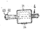
제1도는 본 발명의 직선구동장치의 실시예를 보여주는 폴단면도.1 is a cross-sectional view showing an embodiment of the linear drive device of the present invention.
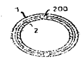
제2도는 제1도에 의한 스핀들 부분을 가진 회전볼의 측면도.2 is a side view of a rotating ball having a spindle portion according to FIG.
제3도는 제1도의 III-III선 단면도.3 is a cross-sectional view taken along the line III-III of FIG.
제4도는 망원경식으로 서로에 관해 미끄럼 이동 가능하며 홈과 스프링에 의하여 뒤틀림이 방지되는 케이싱 부재의 단면도.4 is a cross-sectional view of a casing member telescopically slidable relative to each other and wherein the casing member is prevented from twisting by the groove and the spring.
제5도 및 제6도는 제4도의 변형도.5 and 6 are variations of FIG.
제7도는 이송속도를 매우 느리게 하거나 이송간격을 매우 적게하는데 사용하는 직선구동장치의 도식적(圖式的) 설명도.7 is a schematic explanatory diagram of a linear drive system used for very slow feed speed or very small feed gap.
* 도면의 주요부분에 대한 부호의 설명* Explanation of symbols for main parts of the drawings
M1M2: 모우터 1,1',1" : 외측케이싱부재M 1 M 2 :
2,2' : 내측케이싱부재 3 : 결합요소2,2 ': inner casing member 3: coupling element
4 : 스핀들 11,21 : 단부4: spindle 11,21: end
12,22 : 가이드부분 13,23 : 체결용돌기12,22: Guide part 13,23: Fastening protrusion
16,26 : 고리쇠 25 : 볼트16, 26: hook 25: bolt
31 : 회전볼 넛트(넛트) 34 : 돌기31: rotating ball nut (nut) 34: protrusion
35,43 : 보지링(retaining ring) 41 : 머프카플링35,43: retaining ring 41: muff coupling
42 : 저어널박스 201 : 볼(ball)42: journal box 201: ball
202,203 : 세로홈 500,501,502,600,601 : 치차202,203: Vertical groove 500,501,502,600,601: Gear
본 발명은 넛트를 구동시키는 모우터와 스크류 스핀들을 구동시키는 다른 모우터로 된 2개의 모우터를 가진 직선구동장치에 관한 것이다. 이러한 장치의 예를 들면 스핀들을 구동시키는 1개의 모우터만으로 작업을 하는 배열에 비하여 조절가능한 이송(移送) 속도의 범위가 더 큰 장점이 있다.The present invention relates to a linear drive device having two motors, a motor for driving a nut and another motor for driving a screw spindle. An example of such an apparatus has a greater range of adjustable feed rates compared to an arrangement in which only one motor driving the spindle is used.
2개의 모우터를 동일한 방향으로 회전시키되, 회전수의 차이를 적게하면 이송이 완만하고 매우 느리게 될 수 있다. 1개의 모우터만을 구동시키고, 다른 1개를 정지시키면 이송이 빠르게 될 수 있다. 2개의 모우터를 서로 대향(對向)하여 반전(反轉)시키면 이송이 매우 빠르게 될 수 있다. 1개의 모우터만을 구동시키고, 다른 1개를 정지시키면 이송이 빠르게 될 수 있다. 2개의 모우터를 서로 대향(對向)하여 반전(反轉)시키면 이송이 매우 빠르게 될 수 있다.If two motors are rotated in the same direction, but the difference in the number of revolutions is small, the feed can be smooth and very slow. If only one motor is driven and the other stops, the transfer can be faster. If two motors face each other and are reversed, the transfer can be very fast. If only one motor is driven and the other stops, the transfer can be faster. If two motors face each other and are reversed, the transfer can be very fast.
미국특허 제2,630,022호에서는 2개의 모우터가 달린 개방식 구조로 된 직선구동장치를 제시하였다. 이장치에서는 모우터의 축이 스핀들축에 직각으로 연장하고 있고, 스핀들과 넛트를 별도의 워엄기어를 거쳐 구동하게 한다. 이로 인하여 제작비가 상당히 많이 소요되며, 깨끗하고 밀집된 소형구조의 장치를 만들 수 없다. 이 특허명세서에서는 이러한 구동장치를 항공기에 사용할 것을 제워하면서, 2개의 모우터중 1개가 탈락 되더라도 이 구동장치는 여전히 구동시킬 수 있기 때문에 특히 유리하다고 강조하였다. 그러나, 이러한 장점은 이와 같은 직선구동장치를 2개의 모우터로 운전할 때에는 어는 것에서나 당연히 부수되는 것이다.US Patent No. 2,630,022 proposes a linear drive device having an open structure with two motors. In this system, the axis of the motor extends perpendicular to the spindle axis, and drives the spindle and nut through separate worm gears. As a result, manufacturing costs are considerably high, and a compact and compact device cannot be manufactured. The patent emphasizes the use of such a drive in an aircraft and emphasizes that it is particularly advantageous because the drive can still be driven even if one of the two motors is dropped. However, this advantage is naturally accompanied by freezing when driving such a linear drive with two motors.
또 다른 미국특허 제 2,481,477호에서는 1개의 모우터가 스핀들을 직접 구동시키는 쌍발(雙發) 직선구동 장치를 제시하였는데, 넛트를 구동시키는 모우터는 스핀들의 곁에 놓여 있고, 특수한 톱니장치를 거쳐 스핀들을 구동시킨다.Another U.S. Patent No. 2,481,477 proposes a twin linear drive system in which a single motor drives the spindle directly. Let's do it.
따라서, 본 발명의 목적은 기구적으로 명확하고 간단하며, 염가로 제작할 수 있는 구조로 된 2개의 모우터가 달린 직선 구동장치를 구비함에 있다.Accordingly, an object of the present invention is to provide a linear drive device with two motors having a structure that is mechanically clear and simple and can be manufactured at low cost.
본 발명에 따르면, 축을 중심으로 회전될 수 없으나 서로에 관해 미끄럼운동하여 망원경식으로 신축될 수 있는 두개의 관상 케이싱부재의 워측단부에 각기 부착된 두개의 모우터가 상기 각 관상 케이싱부 재내에 위치된 넛트와 스핀들을 각기 구동하도록 배열된 두개의 모우터를 가진 직선구동장치가 구비된다.According to the present invention, there are two motors respectively attached to the war end portions of two tubular casing members which cannot be rotated about an axis but which can slide telescopically about each other and are located in the respective tubular casing portions. There is provided a linear drive with two motors arranged to drive the nut and the spindle respectively.
본 발명의 실시예를 첨부된 도면을 참조하여 상세히 설명하면 다음과 같다.An embodiment of the present invention will be described in detail with reference to the accompanying drawings.
본 발명에 의한 직선 구동장치에는 망원경식으로 서로 내측으로 변위될 수 있는 2개의 관상 워측 및 내측 케이싱부재(1)(2)가 구비되어 있으며, 상기 케이싱의 각 외측단(外側端)은 (11) 및(21)에서와 같이 보강되어 있다. 이와 같이 보강된 각 케이싱의 각 부에는 모우터(M1)(M2)가 부착되어 있다. 내측케이싱 부재(2)상의 가이드부분(22)과 외측케이싱부재(1)내에 설치된 가이드부분(12)은 정밀한 안내를 위하여 구비된 것이다.The linear drive device according to the present invention is provided with two tubular war side and inner casing members (1) (2), which can be displaced inward to each other telescopically, and each outer end of the casing is (11). ) And (21). The motors M 1 and M 2 are attached to each part of each of the casings thus reinforced. The guide portion 22 on the
상기 보강된 양측 단부(11)(21)에는 체결용 돌기(13)(23)가 설치되어 있으며, 이에 의하여 구동장치에 의해 활동하는 부분이 구동장치와 결합될 수 있다.Fastening
제3도에서 보면, 보강된 단부(21)에는 오목부(24)가 있어서 모우터(M2)를 관상부 끝에 부착시킬 수 있도록 내면에 6각 볼트(25)가 그 안에 들어가게 되어 있다. 모우터(M1)는 관상부 내부에 있는 나사(지면관계 상도면에는 표시되지 아니함)에 의하여 보강된 단부(11)에 모우터(M2)와 같은 방식으로 고정된다. 양쪽모우터(M1)(M2)의 플랜지에는 고리쇠(16)(26)가 있어서 이에 의하여 각 모우터는 보강된 케이싱의 단부(11)와 (21)의 중앙에 위치시킬 수 있게 된다.In FIG. 3, the
그 외에도, 외측과 내측케이싱 부재(1)과 (2)는 서로에 관해 회전되지 않도록 고정된다. 그러나 상호 축방향 미끄럼운동은 가능하도록 배열된다. 제4도는 이 목적을 달성하기 위해외측부분에 2개의 세로홈이 파여 있고, 내측부분에는 2개의 활동(滑動)돌기가 삽입되어 있다.In addition, the outer and
제5도 및 제6도는 또다른 해결방법을 제시하고 있는데, 제5도에 의하면 외측 케이싱부재(1')와 내측 케이싱부재(2')안에 관의 축과 평행으로 주행로(走行路)가 구비되어 있고, 이 안에서 볼(201)이 돌아다닌다. 이러한 방식은 정밀하면 서로 다루기가 쉽다.5 and 6 show another solution. According to FIG. 5, in the outer casing member 1 'and the inner casing member 2', a traveling path is parallel to the axis of the pipe. It is provided, in which the
제6도에서는 외측케이싱 부재(1")에 내치차 형태의 매은 세로홈(202)이 파여있고, 내측케이싱부재(2")에는 상기 내치차와 맞무리는 외치차 형태의 세로홈(203)이 파여있다. 이러한 방식은 큰 힘을 받을 수 있다.In FIG. 6, the inner toothed
망원 경식으로 서로에 관해 미끄럼 운동할 수 있는 원형케이싱을 사용하는 대신에, 외측과 내측케이싱 부재(1)(2)의 횡단면을 4각형 또는 6각형등의 다각형으로도 만들 수 있는데, 이와 같이 하면, 비틀림을 방지 하기 위한 특별한 수단이 필요없게 될 것이다.Instead of using circular casings that can slide relative to each other in telescopic rigidity, the cross-sections of the outer and
모우터(M1)는 중공의 결합요소(3)에 의하여 회전볼 넛트(rotary ball nut)(31)를 회전시킨다. 결합요소(3)의 일측단부(32)는 모우터(M1)의 회전축에 연결되어 있고, 다른 일측단부(33)는 종(鍾) 형태로 넓어져 있어서, 상기 회전볼 넛트(31)가 그 안에 들어가 자데하고 있다. 이 회전볼 넛트는 비틀림을 방지하기 위한 돌기(34)와 변위를 막기 위한 보지링(35)등에 의하여 결합요소에 끝에 고착되어 있다. 양단부 사이에 놓여 있는 관형부분(36)내에는 수ㅡ핀들의 단부가 변위 및 회전될 수 있도록 자리하고 있다.The motor M 1 rotates the
모우터(M2)는 스핀들(4)을 회전시킨다. 이 목적을 위하여 모우터(M2)의 회전축이 머프카플링(41)에 의하여 스핀들의 한쪽 단부에 연결되어 있다. 나사 스핀들(4)에는 제2도에서 보는 바와 같이, 회전볼넛트(31)의 볼에 일치하는 나사를 가지고 있다. 나사 스핀들의 자유단(自由湍)에는 나사 스핀들의 단부에서 회전할 수 있는 저어널박스(42)가 구비되어 있는데, 이러한 저어널박스는 보지 링(43)에 의하여, 축방향이 고정되어 있다. 저어널박스의 외경(外徑)은 결합요소의 관형부분(36)에서 이 저어널박스가 쉽게 미끄럼변위 될 수 있을 정도의 크기로 한다. 이와 같이 나사스핀들의 자유단에 저어널을 부가하는 것은 나사스핀들이 고속으로 회전할 때 그 흔들림을 억제하기 때문에 매우 중요하다.The motor M 2 rotates the spindle 4. For this purpose the rotary shaft of the motor M 2 is connected to one end of the spindle by a muff coupling 41. The screw spindle 4 has a screw corresponding to the ball of the
운전에 있어서는 2개의 모우터(M1)(M2)중 1개만을 사용하거나, 2개를 모두 사용할 수 있다. 사정에 따라서 완만하게, 중간속도로 또는 매우 빠르게 이송을 할 수 있다. 이송방향에 간격(x)(제1도)을 확대, 시키거나 축소시키는 등 임의로 할 수 있다. 예를들면, 2개의 모우터를 가동시키되, 회전수를 약간 차이지게 함으로써 간격(x)을 확대시키는 방향으로 이송을 완만하게 할 수 있고, 서로 반대되는 방향으로 조작하면(2)개의 모우터를 소로 반대되는 회전 방향으로 가동시킴으로써) 이송을 매우 빠르게 할 수 있다. 이에 관하여는 이미 앞에서 설명하였다.In operation, only one of the two motors M 1 and M 2 may be used or both may be used. Depending on the situation, it can be transported smoothly, at medium speed or very fast. The distance x (FIG. 1) may be enlarged, enlarged, or reduced in the conveying direction. For example, the two motors can be operated, but the rotation speed can be slightly different, so that the feed can be smoothed in the direction of increasing the distance (x), and the two motors can be operated in opposite directions. By moving in the opposite direction of rotation), the feed can be made very fast. This has already been described above.
외측과 내측 케이싱부재(1)과(2)의 가이드부분(12)(22)와 나사스핀들의 길이 및 넛트의 축방향길이에 의하여 최대 이송거리, 즉 범위(H)까지의 행정(제1도)이 제한된다.The stroke to the maximum conveying distance, i.e., to the range H, by the lengths of the guide portions 12 and 22 of the outer and
회전볼 넛트를 이에 상응하는 나사스핀들과 함께 사용하면, 빈틈없이 작동되는 고도의 정밀한 직선이송장치를 만들 수 있다. 따라서, 모우터의 회전축은 어느 방향으로든지 빈틈이 없이 정밀하게 배열되어야 한다. 정밀도보다는 가격에 더 역점을 두는 경우에는 간단한 청도제 넛트를 사용할 수도 있다.Rotating ball nuts with corresponding threaded spindles create a highly precise linear feeder that works seamlessly. Therefore, the axis of rotation of the motor must be precisely arranged without gaps in any direction. If you're focusing on price rather than precision, you can also use a simple Qingdao Nut.
힘의 전달을 위한 방법으로서 방사상 형태로 된 체결용 돌기(13)(23)를 사용하는 대신, 다른 여러가지 방법도 사용할 수 있다. 예를들면, 모우터(M1)(M2)의 외측 베어링판에 이러한 용도의 작은 구멍을 뚫을 수도 있다.Instead of using the
이러한 직선구동 장치에 의하면 비용을 적게 하면서 간단한 방법으로 이송운동을 느리게 할 수 있는데, 이러한 경우에는 2개의 모우터를 약간의 속도차를 두면서 작동시킨다. 이와 반대로, 100분의 1밀리 이하로 정밀하게 측정되는 작은 이송스텝을 얻고자 하는 경우에는 스테핑 모우터(stepping motor)를 사용하여야 한다.According to this linear drive device, the feed movement can be slowed down in a simple manner at a low cost. In this case, the two motors are operated with a slight speed difference. On the contrary, a stepping motor should be used to obtain a small transfer step that is precisely measured to less than one hundredth of a millimeter.
제1도에서 도시된 직선구동 장치로써 균일한 작은 이송스텝을 얻고자하는 때에는 제1모우터(M1)로 스테핑 모우터를 사용하고, 제2모우터(M2)로 브레이크에 의하여 정지시키는 모우터를 사용하는 형태를 취할 수도 있다. 예를 들면, 만일 스테핑 모우터(M1)가 1회전할 때마다 1000스텝을 가르키고, 이 모우터가 1스텝만 가도록 조정하면 나사 스핀들의 피치가 2밀리일 때
제1도에 따른 직선구동장치로써 극히 작은 이송스텝을 실시하려면, 서로 다른 2개의 스테핑 모우터를 사용하는 것이 유리하다. 예를들면, 1회전당 1000스텝의 모우터(M1)와 999스텝의 모우터(M2)를 사용하는 경우에, 이 2개의 모우터를 동일한 회전방향으로 1스텝을 가도록 조종하면, 나사스핀들의 나사피치가 2밀리일때에는 이송스텝은
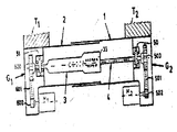
제7도에서 도시된 직선구동장치의 실시예는 비교적 값싼스테핑 모우터를 사용하여 극히 작은 이송스텝을 실현시킬 수 있는 해결방법을 제시한다.The embodiment of the linear drive device shown in FIG. 7 proposes a solution which can realize an extremely small transfer step using a relatively cheap stepping motor.
2개의 모우터(M1)(M2)가 동일한 방향으로 완전히 1회전 하면, 다음에 설명하는 바와같이, 약 1/1000mm정도의 이송(移送)이 있게 된다.When the two motors M 1 and M 2 rotate one complete revolution in the same direction, there will be a transfer of about 1/1000 mm, as will be explained later.
제7도에서 제1도에서와 유사한 부분의부호는 동일한 부호로 표시되어 있다. 망원경식으로 서로를 향해 미끄럼식으로 변위될 수 있는 2개의 외측과 내측 케이싱부재(1)과 (2)내에는 중공의 결합요소(3)와 나사스핀들(4)이 들어 있다. 종모양으로 확대된 일측단부(33)에는 고도로 정밀한 회전볼넛트가 들어 있고, 이 넛트는 빈틈없이 정밀하게 작동되는 나사 스핀들(4)과 맞물려 있다.In Fig. 7, parts similar to those in Fig. 1 are denoted by the same reference numerals. In the two outer and
제1도에 의한 직선구동장치와 제7도의 장치 사이의 차이점은 결합요소(3)와 나사스핀들(4)이 직접 모우터의회전축에 연결되어 있지 않고, 케이싱부재 부분(G1)(G2)내의 (50)(51)에서 각기 분리되어 지지되어 이들이 축방향 및 반경방향 어느 쪽으로도 빈틈이 없다는 것이다.The difference between the linear drive device according to FIG. 1 and the device of FIG. 7 is that the
케이싱부재(G1)(G2)내에는 치차-전동장치가 들어 있는데, 이전동장치에는 치차(500)(600), 치차(502)(602) 및 치차(501)(601)가 포함된다. 치차(502)(602)는 모우터(M1)(M2)에 의하여 구동된다. 모우터(M1)(M2)는 케이싱부재(G1)(G2)의측면에 부착되어 있다. 2개의 치차장치 사이의 잇수비(gear ratios)에는 거의 차이가 없다. 예를 들어 설명하면, 치차(600)에는 톱니는 41개 달려 있고, 치차(602)에는 톱니가 15개 있을때, 그 잇수는 U=

스테핑 모우터를 사용하는 경우에는 직선구동장치가 푸쉬버턴을 누름에 의하여 이동물품운반대(T1)(T2)와 같은 기계부분품를 1/100밀리정도 이동시킬 수 있게 이 모우터를 조종할 수 있다.If a stepping motor is used, the motor can be controlled to move about 1/100 millimeters of mechanical parts such as moving goods carriers (T 1 ) (T 2 ) by pressing the pushbutton. have.
이와 같이 이송스텝 근소한 때에는 자연히 전체부품이 빈틈없이 조작되는 것이 중요하다. 이것은 가볍게 앞에서 잡아끄는 로울러 베어링을 사용하고, 빈틈없이 작동되는 회전볼넛트를 앞에서 말한 나사스핀들및 빈틈없이 조작되는 치차 벨트와 함께 사용하면 실현할 수 있다. 위에서 말한 바와같이, 이동식물품 운반대(T1)(T2)를 극히 작은 스펩으로 이동시키는 직선구동장치를 사용하는 경우에도, 그 이동속도를 빠르게 할 수 있다. 2개의 모우터중 1개만을 구동시키고, 다른 1개를 정지시키면 이송이 빠르게 된다. 제2모우터를 제1모우터와 반대회전 방향으로 구동시키면 이송속도가 배로 증대된다. 1 : 3정도의 중간기어의 톱니비율은 이 경우 중요하지 않다.As such, when the transfer step is small, it is important to naturally operate the entire part without gaps. This can be achieved by using a lightly pulled roller bearing and using a tightly operated rotary nut with the aforementioned screw spindles and a tightly operated toothed belt. As mentioned above, even when a linear drive device for moving the mobile food carrier T 1 (T 2 ) to an extremely small spp can be used, the moving speed can be increased. If only one of the two motors is driven and the other one is stopped, the transfer will be faster. When the second motor is driven in a direction opposite to the first motor, the feed speed is doubled. The tooth ratio of intermediate gears of 1 to 3 is not important in this case.
이동물품 운반대를 단계적으로 1단계씩 추진시키는 직선구동 장치로서, 이송과 정지에 역점을 두는 구동장치는 사용하는 경우 이외에도, 극히 느리게 계속적으로 이동시키는 직선구동장치에도 사용할 수 있다. 이러한 구동장치를 사용하는 설비의 예로서 태양에너지 집광경이 있으며, 이런 집광경은 통상 태양광을 한개의촛점에 집광시키기 위해서 태양을 따라 움직이므로 본 발명의 직선구동 장치를 사용하면 유리하다.As a linear drive device which pushes a moving object carriage step by step, a drive device that focuses on feeding and stopping can be used in a linear drive device that continuously moves continuously very slowly. An example of a facility using such a driving device is a solar energy concentrator, which is advantageous to use the linear drive device of the present invention since it normally moves along the sun to condense the sunlight to one focal point.
Claims (18)
Applications Claiming Priority (3)
| Application Number | Priority Date | Filing Date | Title |
|---|---|---|---|
| CH5025/82-5 | 1982-08-24 | ||
| CH5025/82A CH647306A5 (en) | 1982-08-24 | 1982-08-24 | Linear drive device with two motors |
| CH2303/83A CH664610A5 (en) | 1983-04-29 | 1983-04-29 | LINEAR DRIVE DEVICE. |
Publications (2)
| Publication Number | Publication Date |
|---|---|
| KR840005784A KR840005784A (en) | 1984-11-15 |
| KR870001552B1 true KR870001552B1 (en) | 1987-09-02 |
Family
ID=25690067
Family Applications (1)
| Application Number | Title | Priority Date | Filing Date |
|---|---|---|---|
| KR1019830003729A Expired KR870001552B1 (en) | 1982-08-24 | 1983-08-10 | Linear drive device with two motors |
Country Status (5)
| Country | Link |
|---|---|
| KR (1) | KR870001552B1 (en) |
| DD (1) | DD211768A5 (en) |
| ES (1) | ES8502293A1 (en) |
| IL (1) | IL69552A (en) |
| IT (1) | IT1168629B (en) |
Families Citing this family (1)
| Publication number | Priority date | Publication date | Assignee | Title |
|---|---|---|---|---|
| DE102021119597A1 (en) | 2021-07-28 | 2023-02-02 | Karlsruher Institut für Technologie, Körperschaft des öffentlichen Rechts | Linear drive with two reduction stages |
-
1983
- 1983-08-10 KR KR1019830003729A patent/KR870001552B1/en not_active Expired
- 1983-08-10 IT IT48837/83A patent/IT1168629B/en active
- 1983-08-12 ES ES524932A patent/ES8502293A1/en not_active Expired
- 1983-08-23 IL IL69552A patent/IL69552A/en unknown
- 1983-08-24 DD DD83254194A patent/DD211768A5/en unknown
Also Published As
| Publication number | Publication date |
|---|---|
| DD211768A5 (en) | 1984-07-25 |
| IL69552A0 (en) | 1983-11-30 |
| ES524932A0 (en) | 1984-12-16 |
| IT8348837A0 (en) | 1983-08-10 |
| IT1168629B (en) | 1987-05-20 |
| IT8348837A1 (en) | 1985-02-10 |
| IL69552A (en) | 1987-07-31 |
| KR840005784A (en) | 1984-11-15 |
| ES8502293A1 (en) | 1984-12-16 |
Similar Documents
| Publication | Publication Date | Title |
|---|---|---|
| FI74788B (en) | LINEAERDRIVANORDNING, FOERSEDD MED TVAO MOTORER. | |
| EP0140951B1 (en) | Linear actuator with telescopically variable length | |
| KR920007779B1 (en) | Composite motion guide unit and composite motion guide device using such guide unit | |
| GB2115515A (en) | Rotary-to-linear converter | |
| CA2116879C (en) | Linear actuation roller bearing nut | |
| JP2004508504A (en) | Wave gear device | |
| US6422101B2 (en) | Reinforced lead screw with springless anti-backlash nut | |
| US5117700A (en) | Miniature linear actuator | |
| US3861226A (en) | Linear actuator | |
| CN109109017A (en) | A kind of structured automatical thread-arranging-winding machine structure for cable traction machine people | |
| GB2091375A (en) | A device for converting rotary motion into linear motion | |
| US3081639A (en) | Feed mechanism | |
| US3242755A (en) | Toroidal transmission | |
| KR870001552B1 (en) | Linear drive device with two motors | |
| US4896566A (en) | Motion transforming device, and in particular a speed reduction gear | |
| US6186020B1 (en) | Device for conversion of rotary into axial movement | |
| JP3863182B2 (en) | Device for converting rotational motion into axial motion | |
| US4285249A (en) | Apparatus for causing axial movement | |
| WO1980000032A1 (en) | Apparatus for translating rotary movement to rectilinear movement | |
| JPS6150176B2 (en) | ||
| US6131479A (en) | Device for converting rotary motion into axial motion | |
| US2837937A (en) | Speed changer | |
| US20200182338A1 (en) | Actuating mechanism with a planetary roller screw mechanism | |
| USRE26476E (en) | Kuehnle toroidal transmission | |
| US5331862A (en) | Linear drive for converting a rotational drive movement into a linear output movement |
Legal Events
| Date | Code | Title | Description |
|---|---|---|---|
| A201 | Request for examination | ||
| PA0109 | Patent application |
St.27 status event code: A-0-1-A10-A12-nap-PA0109 |
|
| PA0201 | Request for examination |
St.27 status event code: A-1-2-D10-D11-exm-PA0201 |
|
| R17-X000 | Change to representative recorded |
St.27 status event code: A-3-3-R10-R17-oth-X000 |
|
| PG1501 | Laying open of application |
St.27 status event code: A-1-1-Q10-Q12-nap-PG1501 |
|
| N231 | Notification of change of applicant | ||
| PN2301 | Change of applicant |
St.27 status event code: A-3-3-R10-R13-asn-PN2301 St.27 status event code: A-3-3-R10-R11-asn-PN2301 |
|
| E902 | Notification of reason for refusal | ||
| PE0902 | Notice of grounds for rejection |
St.27 status event code: A-1-2-D10-D21-exm-PE0902 |
|
| P11-X000 | Amendment of application requested |
St.27 status event code: A-2-2-P10-P11-nap-X000 |
|
| P13-X000 | Application amended |
St.27 status event code: A-2-2-P10-P13-nap-X000 |
|
| G160 | Decision to publish patent application | ||
| PG1605 | Publication of application before grant of patent |
St.27 status event code: A-2-2-Q10-Q13-nap-PG1605 |
|
| E701 | Decision to grant or registration of patent right | ||
| PE0701 | Decision of registration |
St.27 status event code: A-1-2-D10-D22-exm-PE0701 |
|
| GRNT | Written decision to grant | ||
| PR0701 | Registration of establishment |
St.27 status event code: A-2-4-F10-F11-exm-PR0701 |
|
| PR1002 | Payment of registration fee |
St.27 status event code: A-2-2-U10-U11-oth-PR1002 Fee payment year number: 1 |
|
| LAPS | Lapse due to unpaid annual fee | ||
| PC1903 | Unpaid annual fee |
St.27 status event code: A-4-4-U10-U13-oth-PC1903 Not in force date: 19900903 Payment event data comment text: Termination Category : DEFAULT_OF_REGISTRATION_FEE |
|
| PC1903 | Unpaid annual fee |
St.27 status event code: N-4-6-H10-H13-oth-PC1903 Ip right cessation event data comment text: Termination Category : DEFAULT_OF_REGISTRATION_FEE Not in force date: 19900903 |
|
| P22-X000 | Classification modified |
St.27 status event code: A-4-4-P10-P22-nap-X000 |
|
| P22-X000 | Classification modified |
St.27 status event code: A-4-4-P10-P22-nap-X000 |