KR870001450B1 - Enclosed type compressor and method for assembling the same - Google Patents
Enclosed type compressor and method for assembling the same Download PDFInfo
- Publication number
- KR870001450B1 KR870001450B1 KR1019850000800A KR850000300A KR870001450B1 KR 870001450 B1 KR870001450 B1 KR 870001450B1 KR 1019850000800 A KR1019850000800 A KR 1019850000800A KR 850000300 A KR850000300 A KR 850000300A KR 870001450 B1 KR870001450 B1 KR 870001450B1
- Authority
- KR
- South Korea
- Prior art keywords
- stator
- casing
- pump assembly
- compression pump
- rotor
- Prior art date
Links
Images


Classifications
-
- F—MECHANICAL ENGINEERING; LIGHTING; HEATING; WEAPONS; BLASTING
- F04—POSITIVE - DISPLACEMENT MACHINES FOR LIQUIDS; PUMPS FOR LIQUIDS OR ELASTIC FLUIDS
- F04C—ROTARY-PISTON, OR OSCILLATING-PISTON, POSITIVE-DISPLACEMENT MACHINES FOR LIQUIDS; ROTARY-PISTON, OR OSCILLATING-PISTON, POSITIVE-DISPLACEMENT PUMPS
- F04C29/00—Component parts, details or accessories of pumps or pumping installations, not provided for in groups F04C18/00 - F04C28/00
-
- F—MECHANICAL ENGINEERING; LIGHTING; HEATING; WEAPONS; BLASTING
- F04—POSITIVE - DISPLACEMENT MACHINES FOR LIQUIDS; PUMPS FOR LIQUIDS OR ELASTIC FLUIDS
- F04B—POSITIVE-DISPLACEMENT MACHINES FOR LIQUIDS; PUMPS
- F04B39/00—Component parts, details, or accessories, of pumps or pumping systems specially adapted for elastic fluids, not otherwise provided for in, or of interest apart from, groups F04B25/00 - F04B37/00
- F04B39/12—Casings; Cylinders; Cylinder heads; Fluid connections
- F04B39/127—Mounting of a cylinder block in a casing
-
- Y—GENERAL TAGGING OF NEW TECHNOLOGICAL DEVELOPMENTS; GENERAL TAGGING OF CROSS-SECTIONAL TECHNOLOGIES SPANNING OVER SEVERAL SECTIONS OF THE IPC; TECHNICAL SUBJECTS COVERED BY FORMER USPC CROSS-REFERENCE ART COLLECTIONS [XRACs] AND DIGESTS
- Y10—TECHNICAL SUBJECTS COVERED BY FORMER USPC
- Y10S—TECHNICAL SUBJECTS COVERED BY FORMER USPC CROSS-REFERENCE ART COLLECTIONS [XRACs] AND DIGESTS
- Y10S417/00—Pumps
- Y10S417/902—Hermetically sealed motor pump unit
-
- Y—GENERAL TAGGING OF NEW TECHNOLOGICAL DEVELOPMENTS; GENERAL TAGGING OF CROSS-SECTIONAL TECHNOLOGIES SPANNING OVER SEVERAL SECTIONS OF THE IPC; TECHNICAL SUBJECTS COVERED BY FORMER USPC CROSS-REFERENCE ART COLLECTIONS [XRACs] AND DIGESTS
- Y10—TECHNICAL SUBJECTS COVERED BY FORMER USPC
- Y10T—TECHNICAL SUBJECTS COVERED BY FORMER US CLASSIFICATION
- Y10T29/00—Metal working
- Y10T29/49—Method of mechanical manufacture
- Y10T29/49229—Prime mover or fluid pump making
- Y10T29/49236—Fluid pump or compressor making
- Y10T29/49245—Vane type or other rotary, e.g., fan
-
- Y—GENERAL TAGGING OF NEW TECHNOLOGICAL DEVELOPMENTS; GENERAL TAGGING OF CROSS-SECTIONAL TECHNOLOGIES SPANNING OVER SEVERAL SECTIONS OF THE IPC; TECHNICAL SUBJECTS COVERED BY FORMER USPC CROSS-REFERENCE ART COLLECTIONS [XRACs] AND DIGESTS
- Y10—TECHNICAL SUBJECTS COVERED BY FORMER USPC
- Y10T—TECHNICAL SUBJECTS COVERED BY FORMER US CLASSIFICATION
- Y10T29/00—Metal working
- Y10T29/49—Method of mechanical manufacture
- Y10T29/49764—Method of mechanical manufacture with testing or indicating
- Y10T29/49778—Method of mechanical manufacture with testing or indicating with aligning, guiding, or instruction
-
- Y—GENERAL TAGGING OF NEW TECHNOLOGICAL DEVELOPMENTS; GENERAL TAGGING OF CROSS-SECTIONAL TECHNOLOGIES SPANNING OVER SEVERAL SECTIONS OF THE IPC; TECHNICAL SUBJECTS COVERED BY FORMER USPC CROSS-REFERENCE ART COLLECTIONS [XRACs] AND DIGESTS
- Y10—TECHNICAL SUBJECTS COVERED BY FORMER USPC
- Y10T—TECHNICAL SUBJECTS COVERED BY FORMER US CLASSIFICATION
- Y10T29/00—Metal working
- Y10T29/49—Method of mechanical manufacture
- Y10T29/49826—Assembling or joining
- Y10T29/4984—Retaining clearance for motion between assembled parts
-
- Y—GENERAL TAGGING OF NEW TECHNOLOGICAL DEVELOPMENTS; GENERAL TAGGING OF CROSS-SECTIONAL TECHNOLOGIES SPANNING OVER SEVERAL SECTIONS OF THE IPC; TECHNICAL SUBJECTS COVERED BY FORMER USPC CROSS-REFERENCE ART COLLECTIONS [XRACs] AND DIGESTS
- Y10—TECHNICAL SUBJECTS COVERED BY FORMER USPC
- Y10T—TECHNICAL SUBJECTS COVERED BY FORMER US CLASSIFICATION
- Y10T29/00—Metal working
- Y10T29/49—Method of mechanical manufacture
- Y10T29/49826—Assembling or joining
- Y10T29/49895—Associating parts by use of aligning means [e.g., use of a drift pin or a "fixture"]
Abstract
내용 없음.No content.
Description
제1도는 본 발명에 의한 밀폐형 압축기의 한 실시예를 나타낸 단면도.1 is a cross-sectional view showing an embodiment of a hermetic compressor according to the present invention.
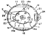
제2도는제1도 선 Ⅱ-Ⅱ의 단면도.2 is a cross-sectional view taken along line II-II of FIG.
제3도에서 제5도는 본 발명에 의한 밀폐형 압축기의 조립공정을 나타낸 설명도.3 to 5 are explanatory views showing the assembling process of the hermetic compressor according to the present invention.
제6도는 본 발명의 의한 조심(調芯)방법의 설명도.6 is an explanatory diagram of a careful method according to the present invention.
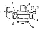
제7도 및 제8도는 본 발명의 다른 실시예를 나타낸 부분 단면도.7 and 8 are partial cross-sectional views showing another embodiment of the present invention.
* 도면의 주요부분에 대한 부호의 설명* Explanation of symbols for main parts of the drawings
11 : 케이싱(casing) 12 : 압축펌프 조립체11
13 : 고정자(stator) 15 : 구동축13
18 : 회전자(rotor) 21 : 조심플레이트(plate)18: rotor 21: watch plate
23 : 보울트(bolt) 26 : 계자코일23: bolt 26: field coil
28 : 커버(cover)28: cover
본 발명은 냉동사이클(cycle)등에서 이용되는 밀폐형 압축기와 그 조립방법에 관한 것이다.The present invention relates to a hermetic compressor used in a refrigeration cycle and the like and a method of assembling the same.
밀폐케이싱속에서 전동 모우터 및 이 전동모우터에 의해 구동되는 압축펌프조립체가 설치되어서 이루어진 밀폐형 압축기에 있어서는 통상·전등모우터와 압축펌프조립체는 각각 별도로 제작되어 밀폐케이싱 내부에 맞춰 넣어서 사용된다.In a hermetic compressor in which an electric motor and a compression pump assembly driven by the electric motor are installed in a hermetic casing, a light motor and a compression pump assembly are separately manufactured and used to fit inside the hermetic casing.
이것을 맞춰넣을때 전동모우터의 회전자는 압축펌프조립체의 구동축에 끼워 붙여서 케이싱의 내부 둘레벽에 끼워붙인 전동모우터의 고정자의 내부둘레에 작은 간격을 사이에 두고 배치된다.When fitting this, the rotor of the electric motor is placed with a small distance between the inner circumferences of the stator of the electric motor fitted to the drive shaft of the compression pump assembly and fitted to the inner circumferential wall of the casing.
이 고정자의 내부둘레와 회전자 외부둘레사이의 간격인 모우터 에어갭(air gap)이 균일하지 않으면, 모우터 견인력이 생겨 회전자 간격이 작은 방향으로 이끌려져서, 모우터를 가동시키는데 필요한 토오크가 커지게 된다. 그러므로 큰 용량의 기동용 전장품(起動用電裝品)을 필요로하게 되거나, 모우터를 대형화시킬 필요가 생기게 된다.If the motor air gap, which is the distance between the inner circumference of the stator and the outer circumference of the rotor, is not uniform, motor traction is generated and the rotor gap is attracted in a small direction, so that the torque required to start the motor is It becomes bigger. Therefore, a large-capacity starting electric equipment is required, or the motor needs to be enlarged.
더우기, 고정자와 회전자의 충돌을 방지하기 위하여 앞에서 설명한 에어갭을 크게하지 않으면 안되고, 모우터의 효율 및 역율(力率)이 저하된다.Furthermore, in order to prevent the stator and the rotor from colliding, the air gap described above must be increased, and the efficiency and power factor of the motor are lowered.
따라서, 고정자와 회전자의 에어갭을 정밀하게 조심할 고안이 필요하게 된다.Therefore, there is a need to devise a precise watch for the air gap of the stator and the rotor.
종래의 밀폐형 압축기 및 그 조립방법으로서는 예를들면 미국특허 제3,805,551호, 미국특허 제3,872,562호에 기술되어있다.Conventional hermetic compressors and their assembling methods are described, for example, in US Pat. No. 3,805,551 and US Pat. No. 3,872,562.
이 압축기는 케이싱의 내부 둘레벽에 고정자를 끼워붙이는 동시에, 케이싱내부에 내부 둘레벽에 직교(直交)로 배치된 플레이트에 대해, 압축펌프 조립체가 고정부착되어 간격게이지, 맨드릴(mandril)등을 이용하여 회전자와 고정자의 조심을 하도록 되어있다,The compressor attaches the stator to the inner circumferential wall of the casing, and the compression pump assembly is fixedly attached to the plate disposed orthogonally to the inner circumferential wall in the casing, thereby using a gap gauge, mandril, or the like. To take care of the rotor and stator,
그러나, 이 구조에 의하면 플레이트는 케이싱의 내부 둘레벽에 대하여 직각으로 배치되는데, 고정자의 내부둘레의 축선에 대하여 반드시 직각이 되는 것이 아니고, 고정자의 내부둘레의 축선에 대하여 회전자의 축선이 경사질 수도 있다.According to this structure, however, the plates are arranged at right angles to the inner circumferential wall of the casing, which is not necessarily perpendicular to the axis of the inner circumference of the stator, but the axis of the rotor is inclined with respect to the axis of the inner circumference of the stator. It may be.
즉, 일반적으로 케이싱의 내부둘레의 벽은 원통형으로 만들어지는데, 그 진원도(眞圓度), 원통도(圓筒度)는 재료의 불균형(특히 늘어남), 배출파이프류, 혹은 단자(端子)의 부착등에 의해서 변형되기 쉽고, 부정확해지는 경우가 많다.In other words, generally the walls of the inner circumference of the casing are made cylindrical, the roundness and the cylindricalness of the material being unbalanced (especially stretched), discharge pipes, or terminals It is easy to deform by adhesion, and it is often inaccurate.
또한, 고정자의 내부둘레로, 코어(core)재를 라미네이팅(laminating)등을 하므로써 고정자의 외부둘레에 대하여 편심(偏心)되기도 하며, 더구나 고정자를 케이싱의 내부둘레의 벽에 끼워붙였을 경우, 케이싱의 내부 둘레벽의 축선에 대하여, 고정자의 내부둘레의 축선이 기울어지기도 한다.In addition, the inner circumference of the stator may be eccentric with respect to the outer circumference of the stator by laminating the core material, etc. Moreover, when the stator is attached to the wall of the inner circumference of the casing, The axis of the inner circumference of the stator may be inclined with respect to the axis of the inner circumferential wall.
이 때문에, 케이싱의 내부 둘레벽을 조립기준으로 해서 전동모우터 및 압축펌프조립체를 조립한 경우에는 전동모우터의 고정자와 회전자의 에어갭의 조정이 부정확하여질 우려가 있다.For this reason, when the electric motor and the compression pump assembly are assembled on the inner circumferential wall of the casing, there is a fear that the air gaps of the stator and the rotor of the electric motor are incorrectly adjusted.
또한 간격게이지, 맨드릴을 이용한 조심작업은 자동화가 곤란하고, 시간이 걸리게 되는 동시에, 조심오차도 크다는 결점이 있다.In addition, a careful operation using a gap gauge and a mandrel is difficult to automate, takes time, and has a large error of carefulness.
또한 전술한 조심작업은 압축펌프조립체와는 반대쪽의 케이싱 개구부(開口部)쪽에서 하게되므로, 케이싱은, 양단(兩端)에 2개의 개구부를 필요로하고, 각각의 개구부에서 전동모우터, 압축펌프조립체를 끼워 넝어서 맞춰야한다.In addition, since the above-mentioned careful operation is performed at the casing opening side opposite to the compression pump assembly, the casing requires two openings at both ends, and the electric motor and the compression pump at each opening. The assembly must be fitted and fitted.
이것은, 조립작업중 케이싱의 개구부를 그때마다 반전(反轉)시켜야하므로, 조립공정수를 증가시키는 원인이 되는 동시에, 개구부의 커버를 부착할때 통상 용접작업을 하기 때문에 그 열의 영향을 고려하여 커버와 내부에 설치된 부품과의 사이의 간격을 크게할 필요가 있으며, 압축기의 전체 높이의 치수를 높히게 하는 원인이 되기도 한다.This causes the casing openings to be reversed at each time during the assembly work, which increases the number of assembly steps, and at the same time, the welding process is usually performed when the cover of the openings is attached. It is necessary to increase the distance between the parts installed inside, and may cause the height of the overall height of the compressor to be increased.
본 발명은 이와같은 점을 고려하여 이루어진 것으로, 내장되어있는 전동모우터의 고정자와 회전자의 초정밀 조심을 행할 수 있음과 동시에, 조립이 용이한 밀폐형 압축기 및 그 조립방법을 제공하는 것을 목적으로 하고 있다.SUMMARY OF THE INVENTION The present invention has been made in view of such a point, and an object of the present invention is to provide a hermetic compressor and a method for assembling thereof, which can be performed with high precision and can be easily assembled. have.
본 발명은, 고정자 및 회전자가 있는 전동모우터와 전술한 전동모우터로 회전구동되는 압축펌프조립체를 밀폐 케이싱 내부에 설치하여 형성된 밀폐형 압축기로서, 고정자의 외부둘레가 케이싱의 내벽에 고정되어, 압축펌프조립체가 고정자의 내부둘레 축선에 대하여 직교하는 방향에 배치되어 중앙에 회전자의 의부지름보다 큰 맞풀린 구멍이 설치되어 있는 판형상(板形狀)의 조심플레이트의 설치면에 고정부착되어 있느 것을 특징으로 하고 있다.The present invention is a hermetic compressor formed by installing an electric motor having a stator and a rotor and a compression pump assembly driven by the aforementioned electric motor inside the hermetic casing, wherein the outer circumference of the stator is fixed to the inner wall of the casing and compressed The pump assembly is fixedly attached to the mounting surface of the plate-shaped guard plate which is arranged in a direction perpendicular to the inner circumferential axis of the stator, and has a centered interposed hole larger than the diameter of the rotor. It features.
또한, 본 발명은 다음의 (a)-(c)의 각 공정으로 이루어진, 밀폐케이싱내에 전동모우터 및 압축펌프조립체가 맞춰넝어진 밀폐형 압축기의 조립방법에 관한 것이다.The present invention also relates to a method of assembling a hermetic compressor in which an electric motor and a compression pump assembly are fitted in a hermetic casing, which is composed of the following steps (a) to (c).
(a) 적어도 한개의 개구부가 있는 케이싱내에 전동모우터의 고정자를 끼워넝고, 고정자의 외부둘레를 케이싱내벽에 고정 부착시킨다.(a) The stator of the electric motor is fitted in a casing with at least one opening, and the outer circumference of the stator is fixedly attached to the inner wall of the casing.
(b) 중앙에 맞뚫린 구멍이 마련되어 있는 판형상의 조심플레이트를 개구부로부터 케이싱내에 끼워넣고, 지그(jig)를 이용하여 고정자의 내부 둘레의 축선과 직교하는 방향에 배치하고, 조심플레이트의 외부둘레를 케이싱 내벽에 고정시킨다.(b) Insert a plate-shaped watch plate provided with a hole in the center from the opening into the casing, and use a jig to place it in a direction orthogonal to the axis of the inner circumference of the stator. Secure to the inner wall of the casing.
(c) 구동축에 전동모우터의 회전자가 끼워붙혀져 있는 압축펌프조립체를 조심플레이트의 표면에 고정자의 내부둘레의 축심과 회진자의 축심이 일치되도록 조심하면서 설치 고정시킨다.(c) The compression pump assembly, in which the rotor of the electric motor is fitted to the drive shaft, is installed and fixed while carefully aligning the axis of the inner circumference of the stator with the axis of the rotator on the surface of the watch plate.
본 발명에 의하면, 조심플레이트가 고정자의 내부둘레의 축선에 대해서 직각으로 배치되어있으므로, 이 조심플레이트에 압축펌프조립체를 부착하는 것만으로서 압축펌프조립체의 구동축에 끼워붙여져 있는 회전자와 고정자의 배부둘레의 양호한 축선평행도를 얻을 수 있다.According to the present invention, since the calibrating plate is disposed at right angles to the axis of the inner circumference of the stator, the circumference of the rotor and stator fitted to the drive shaft of the compressing pump assembly is merely attached to the calibrating plate. Good axis parallelism can be obtained.
또한, 압축펌프조립체의 설치 위치를 약간만 조정하므로서, 고정자와 회전자의 축심의 일치를 도모할 수 있다.In addition, by only slightly adjusting the installation position of the compression pump assembly, the shaft center of the stator and the rotor can be matched.
이렇게하므로서 고정자와 회전자와의 초정밀 조심을 간단하게 행할 수 있으며, 압축기 성능의 향상을 도모할 수 있다.In this way, high precision care can be easily performed between the stator and the rotor, and the compressor performance can be improved.
또한, 맞춰넣는 작업을 케이싱의 한개의 개구부에서 행할수도 있어 조립공정의 축소화, 자동화를 도모할 수 있다.In addition, the fitting operation can be performed at one opening of the casing, so that the assembly process can be reduced and automated.
이하 도면을 참조로하여 본 발명의 실시에 대하여 설명하기로 한다.Hereinafter, embodiments of the present invention will be described with reference to the accompanying drawings.
제1도는 본 발명에 의한 밀폐형 압축기의 한 예를 나타낸 단면도이다.1 is a cross-sectional view showing an example of a hermetic compressor according to the present invention.
부호(11)은 한쪽에 개구부가 있는 케이싱으로 이 케이싱(11)내부에 전동모우터 및 압축펌프조립체(12)가 조립되어 있다.Reference numeral 11 denotes a casing having an opening on one side, in which an electric motor and a
전동모우터의 고정자(13)는 그외부둘레를 케이싱(11)의 내벽에 끼워 맞춰서 고정되어 있다.The
이 고정방법은, 예를들면 고정자(13)의 외부지름을 케이싱(11)의 내부지름보다 약간 크게하여, 억지 끼워맞춤 상태로 고정하는 방법이 있다.This fixing method is, for example, a method in which the outer diameter of the
압축펌프조립체(12)는 내부에 로울링피스톤(rolling piston), 베인(vane), 베인스프링(vane spring)(도시하지 않음)등이 설치되어 있는 실린더(14), 구동축(15), 상기구동축(15)을 지지하는 주베어링(main bearing)(16) 및 보조베어링(sub bearing)(17)으로 이루어지며 구동축(15)의 상단부에는 전동모우터의 회전자(18)가 끼워 붙여져 있다.The
부호(21)는 조심플레이트이며, 이 조심플레이트(21)에 대하여 압축펌프조립체(12)가 부착고정되어 있다.
조심플레이트(21)는 중앙에 회전자(18)의 외부지름보다 크게 맞풀린 구멍(22)이 설치된 판형상을 하고 있으며, 그 외부둘레가 케이싱(11)의 내벽에 레이저(laser) 용접(W)에 의해서 고정되어 있다.The
또한 조심플레이트(21)는 고정자(13)의 내부둘레의 축선에 대하여 직교되는 방향에 배치 고정되어있다.Moreover, the
조심플레이트(21)에 압축펌프조림체(12)의 부착은 주베어링(16)의 부분을 맞뚫린 구멍(22) 내부에 간격을 둔 상태로 삽입하고, 제2도에서 나타낸 바와같이 실린더(14)에 제공된 3개의 아암(arm)(14a)를 보울트(13)를 이용하여 조심플레이트(21)의 아래쪽의 표면에 고정 부착하므로써 이루어지고 있다.Attachment of the compression pump canned
부호 (24)는 케이싱(11)의 옆쪽면(본체부)에 부착된 전기 배선 접속단자이다.
접속단자(24)는 고정자(13)보다 아래쪽에, 용접에 의해 케이싱(11)에 대하여 부착되어 있으므로 고장자 (13)를 케이싱(11) 내부에 끼워넣을때 접속단자(24)의 케이싱내부 방향으로 돌출된 부분과 간섭을 일으키는 것을 방지하기 위해서 고정자(13)의 외부표면 일부에 홈(25)이 마련되어 있다.Since the
접속단자(24)와 고정자(13)의 계자코일(26)은 도선(導線)과 결합유닛(unit)(27)에 의해서 상호 접속되어있다.The
케이싱(11)의 아래쪽 개구부는 커버(28)을 이용하여 폐쇄되며, 케이싱(11)내부는 밀폐구조로 되어 있다.The lower opening of the casing 11 is closed using the
또한 부호(29)는 냉매 흡입관이다.
다음에 이와같은 구조로 이루어지는 밀폐형 압축기의 조립방법에 대해서 설명하면, 우선 케이싱(11)의 개구부로부터 고정자(13)를 끼워넣는데 압입 또는 가열의 끼워 맞추기등으로 케이싱(11)의 내벽에 억지 끼워맞춤 방식으로 고정한다.(제3도 참조),Next, a method of assembling a hermetic compressor having such a structure will be described. First, the
다음으로, 제4도에서 나타낸 바와같이, 조심플레이트(21)를 지그(예를들면 익스펜디드(expanden)맨드릴)(31)를 이용하여 케이싱(11)내부에 끼워넣고 고정자(13)의 내부 둘레축선에 대해 직각으로 배치한다.Next, as shown in FIG. 4, the
지그(31)는 고정자(13)의 내부둘레의 지름보다 작게하여 고정자(13)의 내부에 끼워넣은 다음 유압작용에 의해서 고정자(13)의 내부둘레의 지름과 같은 지름이 될때까지 확장하는 원주부(31a)와 이 원주부(31a)에 직교하도록 설치된 플랜지(flange)부(31b)를 포함하고 있다.
하지만, 원주부(31a)를 미리 고정자의 내부둘레와 거의 동일하게 형성시켜 놓으면, 특히 확장기구를 설치할 필요는 없다.However, if the circumferential portion 31a is formed to be substantially equal to the inner circumference of the stator in advance, there is no need to provide an expansion mechanism in particular.
조심플레이트(21)의 맞뚫린 구멍(22)에 대하여 지그(31)의 원주부(31a)를 삽입하여, 조심플레이트(21)의 표면과 플래지부(31b)를 밀착시킨다.The circumferential portion 31a of the
이 상태에서 지그(31)의 원주부(31b)를 고정자(31)의 내주부에 끼워넣고 조심플레이트(21)와 고정자(13)의 축방향 간격을 소정의 수치로 설정한후, 조심플레이트(21)의 외주부를 케이싱(11)의 내벽에 고정한다.In this state, the circumferential portion 31b of the
이 고정은 케이싱(11)의 외부쪽에서 레이저광을 조사하는 레이저 용접(W)을 이용하는것이 바람직하다.It is preferable to use the laser welding W which irradiates a laser beam from the outer side of the casing 11 for this fixing.
조심플레이트(21)로 고정시킨후 지그(31)를 뽑아낸다.After fixing with the careful plate (21), pull out the jig (31).
조심플레이트(21)는 지그(31)를 이용하여 고정자(13)의 내부둘레의 축선을 공통축선으로하여 부착고정되며, 고정자(13)의 내부둘레축선에 대해서 조심플레이트의 표면이 정확하게 직교하는 상태로 부착 고정된다.The
따라서 만일 케이싱(11)의 내벽에 대해서 고정자(13)의 내부 둘레축선이 기울어지게 설치되어있는 경우일지라도, 조심플레이트(21)의 표면은, 고정자(13)의 내부 둘레축선에 대해서 그 직각도를 고도로 정밀하게 유지할 수 있다.Therefore, even if the inner circumferential axis of the
조심플레이트(21)를 고정 부착시킨후 구동축(15)에 회전자(18)를 끼워붙인 압축펌프 조립체(12)를 케이싱(11) 내부에 조립한다.After the fixed
조심플레이트(21)의 중앙 맞풀린구멍(22)은 회전자(18)의 지름보다 크기때문에 회전자(18)는 그대로 맞뚫린구멍(22)을 통과해서 고정자(13)의 내부 둘레의 위치까지 끼워 넣어진다.Since the center engaged
압축펌프조립체(12)의 주베어링(16)을 맞뚫린구멍(22) 내부에 자유롭게 움직일 수 있도록 끼우는 동시에 실린더(14)의 아암(14a)부분을 조심플레이트(21)의 표면위에 놓는다.The
구동측(15)과 실린더(14)의 아암(14a)부분의 직각도는, 기계가공으로 정밀하게 되어있고, 또한 구동축(15)에 회전자(18)를 끼워 붙이는 것도 정밀하게 할 수 있으므로 상술한 공정에 의한 조립작업만으로 고정자(13)의 내부둘레의 축선과 회전자(18)의 축선(정확하게는 회전자 외부둘레의 축선)의 평행도를 정밀하게 유지할 수 있다.The squareness of the
다음으로, 압축펌프조립체(12)를 조심플레이트(21)의 표면에 접촉시킨 상태로 약간 움직여서 고정자의 외부둘레의 축심과 회전자의 축심을 일치시키는 축심조정을 한다. 이 축심조정은 자동조심기를 이용하여 다음과 같이 행해진다.Next, the
압축펌프조립체(12)를 조심플레이트(21) 위에서 X방향(정 2 도 참조)으로 미끄러지게 하면, 회전자(18)의 외부둘레가 고정자(13)의 내부둘레에 접촉하여 압축펌프조립체(12)를 움직이게하는데 필요한 힘 F(X)은 반작용을 받아서 급작스럽게 증가한다.When the
이점의 위치를 전기적 또는 기계적으로 판독해서 이것을 X1으로 기억한다.The location of the benefit is read electrically or mechanically and stored as X 1 .
다음으로 반대방향으로 같은 동작을 행하게하여, X2를 판독해서 기억한다.Next, the same operation is performed in the opposite direction to read and store X 2 .
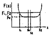
이 X1, X2의 판독에 관하여 제6도를 이용해서 좀 더 상세하게 설명하기로 한다.The reading of X 1 and X 2 will be described in more detail with reference to FIG. 6.
압축펌프조립체(12)를 X축 위에서 이동시키게되면, 회전자(18)의 외부둘레가 고정자(13)의 내부둘레에 접촉을 시작하기까지는 조심플레이트(21)와 압축펌프조립체(12)의 접촉면의 마찰력에 의해서 거의 일정한 FD(압축펌프조립체를 수평으로 움직이는 힘)가 된다.When the
다음으로 회전자(18)와 고정자(13)의 접촉이 시작되면, 우선 구동축(15)과 베어링의 클리어런스(clearance)(보통 0.01-0.03mm의 범위로 설계된다)분 만큼 구동축(15)이 베어링속에서 움직이면서 F(X)가 증가하는데, 더우기 이 공차가 없어지면, 구동축(15)이 휘기 시작한다.Next, when contact between the
이 단계에서 F(X)는 커브를 그리면서 증가한다.At this stage, F (X) increases while drawing a curve.
이 커브도중에서 F(X)의 수치, 즉 F1, F2를 미리 정해놓으므로써 이 X1, X2에 대응하는 수치로써 위치X1, X2가 결정된다.In this curve, the positions X 1 and X 2 are determined as the numerical values corresponding to X 1 and X 2 by specifying the value of F (X), that is, F 1 and F 2 in advance.
이와같이하여 판독된 X1, X2의 수치는 종래와 같이 틈새게이지, 맨드릴에 의한 조심방법으로 수정한 수치와 비교해서 훨씬 정밀도가 좋다.The numerical values of X 1 and X 2 thus read out are much more accurate compared to the numerical values modified by a careful method by a gap gauge and mandrel as in the prior art.
고정자(13)의 내부둘레의 X축위의 축심(XC)는, 회전자(18)가 처음에 어떠한 축심위치 X0에 있었다고 하더라도, XC=(X1+X2)/2의 계산으로 간단하게 산출해낼 수 있다.The axial center X C on the X axis of the inner circumference of the
같은 방법으로, X축과 직교하는 Y축 방향에 대해서도 고정자(13)의 내부둘레의 축심 YC를 산출하여 XC와 YC의 교차점을 구하고, 이것을 고정자(13)의 내부둘레의 축심 CS로 한다.In the same way, in the Y-axis direction perpendicular to the X-axis, the shaft center Y C of the inner circumference of the
이와같이하여 고정자(13)의 내부둘레의 축심과 회전자(18)의 외부둘레 축심의 조심을 행하고 압축펌프조립체(12)를 조심플레이트(21)에 대하여 지지시킨다.In this way, the shaft center of the inner circumference of the
이 지지된 상태에서, 보울트(23)를 이용하여 압축펌프조립체(12)를 조심플레이트(21)에 조여서 고정하는데, 이 고정방법으로서는 조심을 행하기 전에 압축펌프조립체(12)와 조심플레이트(21)를 보울트(23)로 느슨하게 고정시켜 놓고, 조심한 후에 세게 죄어서 결합하는 방법, 조심후의 지지상태에서 압축펌프조립체(12)를 조심플레이트(21) 위에서 회전시켜, 실린더(14)의 아암(14a)의 구멍과 조심플레이트(21)에 뚫린 탭(tap) 구멍의 중심을 맞추는 방법, 또는 실린더(14)의 흡입구멍과 케이싱(11)의 냉매흡입관(29)의 부착구멍을, 예를들면 광학적인 비접촉법으로 위치를 맞추고, 보울트(23)를 아암(14a)의 구멍에 끼워넣어서 조립하는 방법을 생각할 수 있다.In this supported state, the
또한, X축 방향으로서는 실린더(14)의 흡입구멍과 케이싱(11)의 냉매흡입관 부착구멍이 일치할 수 있는 방향으로 미리 압축펌프조립체(12)의 위치를 맞추어 놓게되면, 조심한 다음의 설치작업이 용이하다.In addition, if the position of the
또한, 압축펌프조립체(12)를 X, Y축의 두 방향으로만 이동시키는 것이 아니라, 나아가서는 45°방향으로도 움직일 수 있도록 해 두면, 고정자(13)와 회전자(18)의 조심정밀도를 한층 향상시킬 수 있다.In addition, if the
또한 압축펌프조립체와 조심플레이트의 결합방법으로서, 보울트 이외에 예를들면 레이저 용접(W)에 의해서 행할수도 있다. (제7도 참조)In addition, as a method of coupling the compression pump assembly and the guard plate, it may be performed by laser welding (W) in addition to the bolt. (See Figure 7.)
레이저 용접에 의하면 용접작업으로 인한 부재의 변형이 거의없고, 보울트 구멍, 탭구멍 가공등이 필요치 않고, 또한 각각의 구멍의 중심을 맞추는 작업도 필요하지 않다.According to the laser welding, there is almost no deformation of the member due to the welding operation, no bolt hole, tapped hole processing, etc. are required, and no centering of each hole is necessary.
이와같이하여 압축펌프조립체(12)의 조립을 끝낸 후, 케이싱(11)의 개구부에 대하여 커버(28)를 부착하고, 케이싱 내부를 밀폐구조로 한다.In this manner, after the assembly of the
이상과 같은 조립방법에 의하여 고정자와 회전자의 고도로 정밀한 조심조작을 행하면서, 밀폐형 압축기의 조립을 행할 수 있다.By the assembly method as described above, the hermetic compressor can be assembled while the highly precise and careful operation of the stator and the rotor is performed.
이상과 같이, 본 발명의 실시에 따르면 케이싱에 고정된 고정자의 내부둘레의 축선에 직각으로 부착된 조심플레이트를 이용하여 압축펌프조림체를 부착하는 동시에, 회전자를 고정자의 내부둘레에 직접 접촉시켜서 조심을 행하기 때문에 회전자와 고정자의 정밀한 조심이 가능하다.As described above, according to the embodiment of the present invention, while attaching the compression pump assembly using a watch plate attached at right angles to the axis of the inner circumference of the stator fixed to the casing, the rotor is brought into direct contact with the inner circumference of the stator. Precautions are taken to ensure that the rotor and stator are carefully watched.
특히, 고정자의 내부둘레의 축선이 케이싱 내벽의 축선에 대하여 경사져 있어도 회전자와 고정자의 초정밀한 조심이 가능하다.In particular, even if the axis of the inner circumference of the stator is inclined with respect to the axis of the inner wall of the casing, super precise care of the rotor and the stator is possible.
또한, 종래와 같이 고정자 내주부와 회전자 외주부의 간격에 틈새게이지를 끼운다든가 압축프조립체의 구동축과 고정자 내부둘레사이에 맨드릴을 끼운다든지 할 필요가 없기 때문에 조심작업이 매우 용이하게되고, 자동조립화를 꾀할 수 있다.In addition, since there is no need to insert a gap gauge between the stator inner circumference and the rotor outer circumference, or to insert a mandrel between the drive shaft of the compression assembly and the inner circumference of the stator as in the prior art, careful assembly is very easy and automatic assembly is possible. Can be angry.
또한, 종래와 같은 틈새게이지 및 맨드릴등을 이용한 조심방법과 비교해서 그 조심오차를 대폭적으로 감소시켜 정밀도가 좋은 조심이 가능하다.In addition, compared with the conventional methods using a gap gauge, mandrel, and the like, it is possible to significantly reduce the error of the watch and to be careful with good precision.
이와같이 전동모우터의 회전자와 고정자와의 초정밀 조심이 가능하기 때문에, 콤팩트(compact)한 전동모우터로 효율이 좋은 성능을 발휘할 수 있어서, 압축기의 기동성능의 향상을 꾀할 수 있다.In this way, since high precision care is possible between the rotor and the stator of the electric motor, a compact electric motor can exhibit efficient performance, thereby improving the starting performance of the compressor.
또한, 전동모우터 및 압축펌프조립체를 케이싱 내부에 조립하는 작업을 한 방향에서 할 수 있으므로, 케이싱에 개구부가 하나 있으면 모든 설치를 이 개구부에서 행할 수 있다.In addition, since the operation of assembling the electric motor and the compression pump assembly in the casing can be performed in one direction, if the casing has one opening, all installations can be performed in this opening.
따라서 종래와 같이, 조립도중에 케이싱을 뒤집을 필요가 없고, 조립공정의 축소화 및 자동화를 꾀할수 있다.Therefore, as in the prior art, there is no need to turn over the casing during assembly, and the assembly process can be reduced in size and automated.
또한, 케이싱의 일단을 처음부터 밀봉한 구조로 할 수 있으므로 조립작업을 완료한 후 개구부에 커버를 부착하는 공정이 종래와 비교해서 한 공정이 감소되고, 조립이 용이할 뿐만 아니라 케이싱에 커버를 울접할 때의 열의 영향을 고려할 필요가 없으므로 계자코일(26)과 케이싱(11)의 틈새를 작게할 수 있어서, 케이싱의 세로 방향길이를 축소할 수가 있다.In addition, since one end of the casing can be sealed from the beginning, the process of attaching the cover to the opening after completing the assembly work is reduced compared to the conventional one, and the assembly is easy, and the cover is attached to the casing. Since it is not necessary to consider the influence of heat at the time of contact, the clearance between the
또한, 고정자의 윗족으로부터 하등의 구성부재를 끼워넣을 일도 없으므로 계자코일(26)의 윗족에 있어서, 케이싱(11)은 U자형(제1도 참조)의 밀폐성형(成形)이 가능하고 윗쪽에 있는 계자코일(26)의 불필요한 길이를 대폭적으로 감소할 수 있다. 이것에 의하여 코일재의 절감, 모우터효율의 향상을 꾀할 수 있다.In addition, since the lower part of the
더구나, 조심플레이트의 고정, 압축펌프조립체의 부착, 커버설치등을 레이저 용접을 이용하여 행하므로써, 조립시의 변형을 방지할 수 있다.In addition, deformation of the assembly can be prevented by fixing the guard plate, attaching the compression pump assembly, and installing the cover using laser welding.
또한, 본 발명의 실시에 있어서는, 가장 정밀하게 조립할 수 있는 것이다.In addition, in the practice of the present invention, it is possible to assemble the most precisely.
조심플레이트(21)의 중앙에 맞풀린 구멍(22)에 압축펌프조립체(12)의 주베어링(16)의 외부둘레를 자유롭게 움직일 수 있도록 끼우고 그후, 자동조심기를 이용하여 조심조작을 행하는 것에 대해서 설명했는데, 자동조심기를 이용하는 대신에 맞풀린구멍(22)과 주베어링(16)의 틈새를 충분히 작게한다거나, 맞풀린구멍(22)에 주베어링(16)을 압입하도록 하면 전술한 조심조작을 생략할 수 있다.Inserting the outer circumference of the
이 방법은 전술한 실시예에서 나타낸 조심조작을 행하는 것에 비하면 조림정밀도가 떨어지긴 하지만, 종래의 것보다는 정밀도가 좋게 조립할 수가 있다.This method has a lowered planting precision compared to performing the careful operation shown in the above-described embodiment, but can be assembled with higher precision than the conventional one.
또한, 조심조작은 압축펌프조립체(12)의 위치를 고정해 두고 고정자(13)쪽을 이동시켜서 하도록 해도좋다.In addition, careful operation may be performed by fixing the position of the
또한, 조심플레이트(21)의 압축펌프조립체(12)의 부착면을 조심플레이트(21)의 아래쪽에 형성한 예를보였는데, 중앙의 풀린구멍(22)을 압축펌프조립체(12)의 실린더(14)가 삽입할 수 있는 형상으로 하여두면, 조심플레이트(21)의 윗쪽에 압축펌프조립체(12)의 설치면을 형성할 수 있다. (제8도 참조)In addition, an example in which the attachment surface of the
이 경우에는 중앙의 맞풀린구멍(22)의 형상에 맞추어서 실린더(14)부분을 맞끼워서, 그후 실린더(14)를 회전시켜서 아암(14A)의 보울트 구멍과 조심플레이트(21)의 탭구멍을 일치시켜, 보울트를 이용하여 조심플레이트(21)의 윗면쪽에 부착 고정시킬 수 있다.In this case, the portion of the
더구나 케이싱은 양쪽에 개구 부를 가지고 있는 것이라도 사용가능하며, 또한 완전하게 원통형으로 되어있지 않는 것이라도 본 발명에 사용할 수 있다.Moreover, a casing can be used even if it has an opening part in both sides, and can be used for this invention even if it is not completely cylindrical.
이 경우에는 회전자를 압축펌프조립체와 반대축의 케이싱 개구부로부터 끼워넣을 수 있으므로 조심플레이트의 맞풀린 구멍을 회전자보다 작게 하여도 좋다.In this case, since the rotor can be inserted from the casing opening on the opposite shaft to the compression pump assembly, the engaged hole of the guard plate may be made smaller than the rotor.
또한, 본 발명의 실시에 있어서는 압축펌프조립체를 로우터리 압축기에 대해 설명했는데, 그외에 왕복압축기, 스크로울(scroll) 압축기에 적용할지라도 동일한 효과를 얻을 수 있다.In addition, in the practice of the present invention, the compression pump assembly has been described with respect to the rotary compressor. In addition, the same effect can be obtained even when applied to the reciprocating compressor and the scroll compressor.
또한, 고정자의 외부둘레를 직접 밀폐케이싱 내벽에 접촉시켜 부착한 예를 나타냈는데, 밀폐케이싱의 내부에 또다시 원통형의 내부 케이싱을 마련하고 모우터 및 압축펌프조립체를 전술한 내부 케이싱에 조립하도록 한 구조의 것일지라도, 동일한 효과를 얻을 수 있다.In addition, an example in which the outer circumference of the stator is directly contacted with the inner wall of the sealed casing is attached, and the cylindrical inner casing is again provided inside the sealed casing to assemble the motor and the compression pump assembly to the inner casing described above. Even with the structure, the same effect can be obtained.
이상 설명한 바와같이, 본 발명에 의하면 전동모우터의 회전자와 그정자의 초정밀 조심이 가능하며 압측기의 성능을 대폭적으로 향상시킬 수 있다.As described above, according to the present invention, the super precision of the rotor and the sperm of the electric motor is possible, and the performance of the pressure gauge can be greatly improved.
또한, 개구부가 1개만 설치된 케이싱에 대하여 한폭 방향으로부터만 맞춤 작업을 할 수 있어서, 조립작업이 용이함과 동시에 조립의 자동화가 가능하다.Moreover, the fitting work can be made only from the width direction with respect to the casing provided with only one opening, so that the assembling work is easy and the assembly can be automated.
더구나 전동모우터의 소형화, 케이싱의 전체 높이의 축소화를 꾀할 수 있어서, 콤팩트한 밀폐형 압축기를 얻을 수 있다.In addition, it is possible to reduce the size of the electric motor and reduce the overall height of the casing, whereby a compact hermetic compressor can be obtained.
Claims (4)
Applications Claiming Priority (2)
| Application Number | Priority Date | Filing Date | Title |
|---|---|---|---|
| JP59036482A JPS60182386A (en) | 1984-02-28 | 1984-02-28 | Sealed type compressor and its assembly |
| JP59-36482 | 1984-02-28 |
Publications (1)
| Publication Number | Publication Date |
|---|---|
| KR870001450B1 true KR870001450B1 (en) | 1987-08-06 |
Family
ID=12471034
Family Applications (2)
| Application Number | Title | Priority Date | Filing Date |
|---|---|---|---|
| KR1019850000800A KR850007655A (en) | 1984-02-28 | 1985-02-08 | Hermetic compressor and assembly method |
| KR1019850000800A KR870001450B1 (en) | 1984-02-28 | 1985-02-08 | Enclosed type compressor and method for assembling the same |
Family Applications Before (1)
| Application Number | Title | Priority Date | Filing Date |
|---|---|---|---|
| KR1019850000800A KR850007655A (en) | 1984-02-28 | 1985-02-08 | Hermetic compressor and assembly method |
Country Status (6)
| Country | Link |
|---|---|
| US (2) | US4584750A (en) |
| JP (1) | JPS60182386A (en) |
| KR (2) | KR850007655A (en) |
| DE (1) | DE3506777A1 (en) |
| GB (1) | GB2156008B (en) |
| IT (1) | IT1181759B (en) |
Families Citing this family (15)
| Publication number | Priority date | Publication date | Assignee | Title |
|---|---|---|---|---|
| JPS60182386A (en) * | 1984-02-28 | 1985-09-17 | Toshiba Corp | Sealed type compressor and its assembly |
| IT1182640B (en) * | 1985-10-29 | 1987-10-05 | Aspera Spa | PROCEDURE AND DEVICE FOR THE ASSEMBLY OF ROTARY COMPRESSORS, PARTICULARLY FOR GROUPS OF COMPRESSORS OF REFRIGERATING AND SIMILAR MACHINES |
| US5226294A (en) * | 1992-04-28 | 1993-07-13 | Thermo King Corporation | Compressor arrangement suitable for transport refrigeration systems |
| GB2314593B (en) | 1996-06-28 | 1999-11-10 | Thomas Industries Inc | Two-cylinder air compressor |
| JP3696398B2 (en) | 1997-04-28 | 2005-09-14 | Ntn株式会社 | Hydrostatic magnetic compound bearing and spindle device |
| DE19857560A1 (en) * | 1997-12-23 | 1999-06-24 | Luk Fahrzeug Hydraulik | Pump unit without own bearing |
| US6379130B1 (en) * | 2000-06-09 | 2002-04-30 | Tecumseh Products Company | Motor cover retention |
| JP4371189B2 (en) * | 2000-08-25 | 2009-11-25 | 株式会社富士通ゼネラル | Alignment device for scroll compressor and alignment method thereof |
| US7604466B2 (en) * | 2005-01-31 | 2009-10-20 | Tecumseh Products Company | Discharge muffler system for a rotary compressor |
| JP2007092643A (en) * | 2005-09-29 | 2007-04-12 | Mitsubishi Electric Corp | Rotary compressor and method for manufacturing rotary compressor |
| US8152497B2 (en) * | 2005-10-24 | 2012-04-10 | Tecumseh Products Company | Compressor |
| CN103481016B (en) * | 2012-06-14 | 2016-03-30 | 珠海格力节能环保制冷技术研究中心有限公司 | A kind of rotary double cylinder compressor pump body assembly method |
| JP6477137B2 (en) * | 2015-03-27 | 2019-03-06 | 株式会社富士通ゼネラル | Rotary compressor |
| KR101727801B1 (en) * | 2015-05-22 | 2017-04-17 | 엘지전자 주식회사 | A rotary compressor and a method manufacturing the same |
| US10916989B2 (en) * | 2016-08-10 | 2021-02-09 | Mitsubishi Electric Corporation | Motor, compressor, refrigerating and air conditioning apparatus, and method for manufacturing motor |
Family Cites Families (15)
| Publication number | Priority date | Publication date | Assignee | Title |
|---|---|---|---|---|
| US2243464A (en) * | 1932-09-30 | 1941-05-27 | Gen Motors Corp | Method of making motor-compressor unit for refrigeration |
| US2043215A (en) * | 1933-05-20 | 1936-06-02 | Gibson Electric Refrigerator | Unitary motor-pump assembly |
| US2294037A (en) * | 1937-04-30 | 1942-08-25 | Gen Motors Corp | Method of making motor-compressor units for refrigeration |
| US2246272A (en) * | 1940-08-04 | 1941-06-17 | Davidson William Ward | Rotary pump |
| US2395065A (en) * | 1941-05-28 | 1946-02-19 | Gen Motors Corp | Refrigerating apparatus |
| US2423750A (en) * | 1943-07-03 | 1947-07-08 | Gibson Refrigerator Co | Method of assembling electric motors |
| US2629542A (en) * | 1948-03-12 | 1953-02-24 | Therma Fabrik Fur Elek Sche He | Motor-driven compressor |
| US3526942A (en) * | 1967-06-21 | 1970-09-08 | Tokyo Shibaura Electric Co | Motor driven rotary compressors |
| US3875646A (en) * | 1971-04-19 | 1975-04-08 | Richard D Pfeiffer | Differential test assembly and method of assembling a differential |
| US3850551A (en) * | 1973-05-24 | 1974-11-26 | Fedders Corp | Compressor housing |
| US3872562A (en) * | 1973-10-15 | 1975-03-25 | Fedders Corp | Method of compressor assembly |
| NL7609887A (en) * | 1975-09-13 | 1977-03-15 | Schloemann Siemag Ag | METHOD AND DEVICE FOR THE FORMING OF HOLLOW BODIES FROM THERMO-PLASTIC MATERIALS BY BLADDER EXTRUSION. |
| JPS5252968U (en) * | 1975-10-15 | 1977-04-15 | ||
| JPS538807A (en) * | 1976-07-13 | 1978-01-26 | Matsushita Electric Ind Co Ltd | Rotary compressor |
| JPS60182386A (en) * | 1984-02-28 | 1985-09-17 | Toshiba Corp | Sealed type compressor and its assembly |
-
1984
- 1984-02-28 JP JP59036482A patent/JPS60182386A/en active Pending
-
1985
- 1985-02-08 KR KR1019850000800A patent/KR850007655A/en not_active IP Right Cessation
- 1985-02-08 KR KR1019850000800A patent/KR870001450B1/en not_active Application Discontinuation
- 1985-02-26 DE DE19853506777 patent/DE3506777A1/en active Granted
- 1985-02-28 IT IT47748/85A patent/IT1181759B/en active
- 1985-02-28 US US06/706,624 patent/US4584750A/en not_active Expired - Lifetime
- 1985-02-28 GB GB08505245A patent/GB2156008B/en not_active Expired
-
1987
- 1987-04-21 US US07/040,714 patent/US4743177A/en not_active Expired - Fee Related
Also Published As
| Publication number | Publication date |
|---|---|
| US4584750A (en) | 1986-04-29 |
| KR850007655A (en) | 1985-12-07 |
| US4743177A (en) | 1988-05-10 |
| GB2156008A (en) | 1985-10-02 |
| GB8505245D0 (en) | 1985-04-03 |
| DE3506777A1 (en) | 1985-08-29 |
| IT8547748A1 (en) | 1986-08-28 |
| DE3506777C2 (en) | 1989-02-02 |
| GB2156008B (en) | 1987-06-17 |
| JPS60182386A (en) | 1985-09-17 |
| IT8547748A0 (en) | 1985-02-28 |
| IT1181759B (en) | 1987-09-30 |
Similar Documents
| Publication | Publication Date | Title |
|---|---|---|
| KR870001450B1 (en) | Enclosed type compressor and method for assembling the same | |
| EP1234981B1 (en) | A hermetic scroll compressor | |
| US6454549B2 (en) | Motor cover retention | |
| US3606594A (en) | Hermetically sealed motor/compressor apparatus | |
| US20020047391A1 (en) | Hermetic motor compressor and method assembling the same | |
| JP3260518B2 (en) | Scroll compressor and assembly method thereof | |
| JP2018145936A (en) | Rotary compressor and manufacturing method of rotary compressor | |
| JPH09287585A (en) | Enclosed electric compressor | |
| US4652782A (en) | Flanged stator assembly for dynamoelectric machine | |
| US6687992B2 (en) | Assembly method for hermetic scroll compressor | |
| CA2464216C (en) | Rotary compressor having two-piece separator plate | |
| CN113803254A (en) | Compressor and manufacturing method thereof | |
| CN111656652A (en) | Control device integrated rotating electric machine | |
| US3872562A (en) | Method of compressor assembly | |
| JP2002502009A (en) | Hermetically sealed compressor | |
| US3493794A (en) | Method of manufacture of electric motor and electric motor stator construction | |
| US20020083572A1 (en) | Motor stator with loose laminations | |
| US4773153A (en) | Method of manufacture of a flanged stator assembly for dynamoelectric machine | |
| CN113708538A (en) | Motor stator fixing structure and method, motor and compressor | |
| KR102385273B1 (en) | Electric compressor and manufacturing method for electric compressor | |
| CN110266158B (en) | Assembling process of brushless motor | |
| CN113949234B (en) | Motor stator assembling method | |
| US20220320941A1 (en) | Rotary electric machine and pump | |
| US20220320942A1 (en) | Rotary electric machine and pump | |
| KR101196539B1 (en) | Airtight type electric compressor |
Legal Events
| Date | Code | Title | Description |
|---|---|---|---|
| E902 | Notification of reason for refusal | ||
| E601 | Decision to refuse application |