KR870000490B1 - Method of/and apparatus for attaching fly strips to a slide fastener chain - Google Patents
Method of/and apparatus for attaching fly strips to a slide fastener chain Download PDFInfo
- Publication number
- KR870000490B1 KR870000490B1 KR1019850005690A KR850005690A KR870000490B1 KR 870000490 B1 KR870000490 B1 KR 870000490B1 KR 1019850005690 A KR1019850005690 A KR 1019850005690A KR 850005690 A KR850005690 A KR 850005690A KR 870000490 B1 KR870000490 B1 KR 870000490B1
- Authority
- KR
- South Korea
- Prior art keywords
- strip
- phs
- fly strip
- fly
- sewing machine
- Prior art date
Links
Images


Classifications
-
- A—HUMAN NECESSITIES
- A44—HABERDASHERY; JEWELLERY
- A44B—BUTTONS, PINS, BUCKLES, SLIDE FASTENERS, OR THE LIKE
- A44B19/00—Slide fasteners
- A44B19/24—Details
- A44B19/26—Sliders
- A44B19/30—Sliders with means for locking in position
-
- D—TEXTILES; PAPER
- D05—SEWING; EMBROIDERING; TUFTING
- D05B—SEWING
- D05B35/00—Work-feeding or -handling elements not otherwise provided for
- D05B35/06—Work-feeding or -handling elements not otherwise provided for for attaching bands, ribbons, strips, or tapes or for binding
- D05B35/064—Work-feeding or -handling elements not otherwise provided for for attaching bands, ribbons, strips, or tapes or for binding for attaching slide fasteners
Abstract
Description
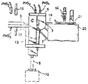
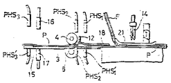
제1도는 본 발명을 실현한 플라이 스트립 부착장치의 일부 파단 사시도이다.1 is a partially broken perspective view of the fly strip attaching device of the present invention.
제2도는 연속 슬라이드 파스너 체인에 재봉될 연속 플라이 스트립의 부분 평면도이다.2 is a partial plan view of a continuous ply strip to be sewn on the continuous slide fastener chain.
제3도는 일부 부품이 생략되거나 파단된 제1도 장치의 측면도이다.3 is a side view of the FIG. 1 device with some components omitted or broken.
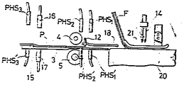
제4도는 일부 부품이 생략되거나 파단된, 제1도 장치의 플라이 스트립 이송 스테이션의 정면도이다.4 is a front view of the fly strip transfer station of the FIG. 1 device with some parts omitted or broken.
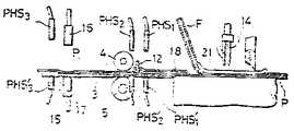
제5도는 재봉 스테이션이 일부 도시된 제4도의 Ⅴ-Ⅴ선을 따른 횡단면도이다.FIG. 5 is a cross sectional view along line V-V of FIG. 4 with a part of the sewing station shown.
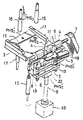
제6도는 제4도의 플라이 스트립 이송 스테이션의 일부 파단 투시도이다.6 is a partially broken perspective view of the fly strip transfer station of FIG.
제7a도-제7c도는 연속 플라이 스트립 재봉의 초기 단계를 나타내는 장치의 일부 파단 횡단면도이다.7A-7C are some broken cross-sectional views of the device showing the initial stage of continuous fly strip sewing.
제8도는 제7a도를 수정한 개략적 횡단면도이다.8 is a schematic cross-sectional view modified from FIG. 7a.
제9a도-제9f도는 장치의 작동 주기를 개략적인 단면도로 도시한 것이되, 제9d도-제9f도는 각각 제7a도-제7c도의 반복인 횡단면도이다.9a-9f show in schematic cross-sectional view the operating cycle of the device, with FIGS. 9d-9f being cross sectional views of the repetition of FIGS. 7a-7c respectively.
제10도는 연속 플라이 스트립 재봉의 최종 단계를 도시한 개략적인 횡단면도이다.10 is a schematic cross sectional view showing the final stage of continuous fly strip sewing.
* 도면의 주요부분에 대한 부호의 설명* Explanation of symbols for main parts of the drawings
P : 플라이 스트립 F : 파스너 체인P: fly strip F: fastener chain
PHS : 광원 PHS' : 광전지PHS: Light source PHS ': Photocell
1 : 이송 스테이션 2 : 재봉틀1: transfer station 2: sewing machine
3 : 하부 가이드 4, 5 : 이송 로울러3:
8 : 브래킷트 9 : 피스톤 로드8: Bracket 9: Piston Rod
10, 13 : 공기 실린더 15 : 계단부10, 13: air cylinder 15: step portion
16 : 분사 파이프 17 : 흡입 파이프16: injection pipe 17: suction pipe
19 : 압축 스프링19: compression spring
본 발명은 플라이 스트립(fly strip : 바지의 앞 가리개 즉, 저피 가리개)의 제조에 관한 것으로 특히 연속 플라이 스트립을 연속 슬라이드 파스너 체인에 부착하는 방법 및 장치에 관한 것이다.FIELD OF THE INVENTION The present invention relates to the manufacture of fly strips, i.e. low skin screens, and more particularly to methods and apparatus for attaching continuous fly strips to a continuous slide fastener chain.
미특허 제3,750,104호에는 다수의 플라이 스트립 조각을 하나씩 연속 슬라이드 파스너 체인에 자동적으로 부착시키는 장치가 개시되어 있다. 여기서, 플라이 스트립은 재봉틀의 간헐 작동에 맞추어 작동하는 이송 로울러에 의해 간헐적으로 작동가능한 재봉틀로 이송된다. 연속 길이의 파스너 체인은 파스너 체인을 플라이 스트립 조각에 붙이기 위한 재봉틀로 연속적으로 이송된다. 재봉틀의 간헐작동은 재봉 스테이션에서 광전지 검출기에 의해 제어된다. 검출기는 한 조각의 플라이 스""""US Patent No. 3,750, 104 discloses a device for automatically attaching multiple pieces of ply strips one by one to a continuous slide fastener chain. Here, the fly strip is conveyed to the sewing machine which is operable intermittently by a transfer roller which operates in accordance with the intermittent operation of the sewing machine. The continuous length fastener chains are continuously transferred to a sewing machine for attaching the fastener chains to the fly strip pieces. Intermittent operation of the sewing machine is controlled by a photocell detector at the sewing station. Detector is a piece of ply
본 발명은 종래 기술에 비해 상당히 진보되고 효율이 개선되는데, 이는 연속 슬라이드 파스너 체인에 연속 플라이 스트립을 중단없이 연속적으로 재봉하는 방법 및 장치를 제공함으로써 이루어지며, 이에 의해 플라이 스트립은 재봉 스테이션에 연속적으로 공급되고 따라서 생산률을 높일 수 있게 된다.The present invention is considerably advanced and improved in efficiency compared to the prior art, which is achieved by providing a method and apparatus for continuously sewing a continuous fly strip without interruption in a continuous slide fastener chain, whereby the fly strip is continuously fed to the sewing station. Supply, thus increasing production rates.
본 발명에 따른 자동 조립에서, 연속 플라이 스트립은 재봉틀의 연속 작동에 의해 연속 슬라이드 파스너 체인에 연속적으로 재봉된다. 플라이 스트립은 재봉틀에 차례로 공급된다. 이 공급도중, 후속 플라이 스트립은 이송 스테이션에서 선행 플라이 스트립에 포개진다. 선행플라이 스트립이 재봉틀에 공급되어 파스너체인에 재봉될 때, 후속 플라이 스트립은 재봉틀에 공급을 정지시키는 정지장치에 의해 그 포개진 위치에서 기다리게 된다. 선행 플라이 스트립의 재봉이 진행됨에 따라 선행 플라이 스트립의 후미단부가 후속 플라이 스트립의 선행 단부 아래로 부터 빠져나올 때, 후속 플라이 스트립은 선행 플라이 스트립의 재봉이 진행되는 속도보다 더 빠른 속도로 재봉 스테이션으로 진행된다. 그래서 후속 플라이 스트립의 전단부는 선행 플라이 스트립이 재봉 스테이션에 도착할 때까지 선행 플라이 스트립의 후미단부를 따라 잡는다.In the automatic assembly according to the invention, the continuous ply strip is successively sewn on the continuous slide fastener chain by the continuous operation of the sewing machine. The fly strips are in turn fed to the sewing machine. During this feeding, subsequent ply strips are superimposed on the preceding ply strips at the transfer station. When the preceding ply strip is fed to the sewing machine and sewed on the fastener chain, the subsequent ply strip is waited in its nested position by a stop device which stops feeding the sewing machine. As the sewing of the preceding fly strip proceeds, when the trailing end of the preceding fly strip exits from below the leading end of the subsequent fly strip, the subsequent fly strip is brought to the sewing station at a faster rate than the sewing of the preceding fly strip proceeds. Proceed. The front end of the subsequent fly strip thus catches up with the trailing end of the preceding fly strip until the preceding fly strip arrives at the sewing station.
본 발명은 또한 연속된 길이의 재료 같이 개별적으로 또는 함께 다른 조각에 재봉될 다른 형태의 작업들에도 비슷하게 응용할 수 있다. 본 발명에 의해 얻어지는 재봉작동효율 및 개선된 생산에 대한 이익은 플라이 스트립을 사용한 바람직한 실시예로만 한정되지 않는다.The present invention is also similarly applicable to other forms of work to be sewn on different pieces, either individually or together, such as continuous lengths of material. The sewing operation efficiency and the benefit to improved production obtained by the present invention are not limited to the preferred embodiment using a fly strip.
본 발명의 다른 발명적 특징, 목적 및 장점은 바람직한 실시예의 상세한 설명을 참조하면 당업자에게 명백해질 것이다.Other inventive features, objects, and advantages of the present invention will become apparent to those skilled in the art upon reference to the detailed description of the preferred embodiments.
본 발명의 목적은, 연속으로 작동하는 재봉틀을 사용하여 이전에는 가능하지 않았던, 고 생산률로 연속길이의 슬라이드 파스너 체인(F)에 결합된 일련의 플라이 스트립 조각(P)을 생산하는 것이다. 본 발명의 궁극적 결과는 제2도에 도시되어 있는데, 여기서 플라이 스트립 조각(P)들이 서로 단부를 맞대어 배치된채 플라이 스트립과 파스너 체인이 함께 연속으로 재봉된 것이 나타나 있다.It is an object of the present invention to produce a series of pieces of fly strips (P) bonded to a continuous-length slide fastener chain (F) at high production rates, which were not previously possible using a continuously operating sewing machine. The ultimate result of the present invention is shown in FIG. 2, where the fly strips and fastener chains are sewn together in succession with the fly strip pieces P placed opposite one another.
제1도 및 제3도에는 본 발명에 따라 중단없이 연속 플라이스트립(P)을 연속 슬라이드 파스너 체인(F)에 연속적으로 부착하는 자동장치가 도시되어 있다. 장치는 일반적으로 재봉틀(2)과 연속플라이 스트립(P)을 재봉틀(2)에 연속적으로 자동 공급하는 플라이 스트립 이송 스테이션(1)으로 구성된다.1 and 3 show an automatic device for continuously attaching the continuous flystrip P to the continuous slide fastener chain F without interruption in accordance with the present invention. The apparatus generally consists of a fly
재봉틀(2)은 시판하는 통상형태의 것이다. 재봉틀은 재봉될 플라이 스트립(P)을 그 위에서 지지하는 지지 테이블(20), 노루발(21) 및 플라이 스트립(P)을 파스너 체인에 재봉하는 한 쌍의 바늘(14)을 포함한다. 파스너 체인(F)는 재봉틀의 상부에 지지된 도시되지 않은 리이드(read)로 부터 지지 테이블(20)과 노루발(21) 사이의 공간을 통해 재봉 스테이션으로 연속 공급된다. 재봉틀(2) 자체의 상세한 내용은 여The
재봉작동을 시작하기 위해, 연속 플라이 스트립(P)의 전방 일부는 이송 스테이션(1)의 상류로 연장한 하부 가이드(3) 상에 손으로 놓여지고 다음에 하부 가이드(3)를 따라 이송 스테이션(1)으로 손으로 도입된다. 이렇게 도입된 플라이스트립(P)은 피구동 이송 로울수단에 의해 재봉틀(2)로 공급되며, 여기서 플라이 스트립(P)은 파스너 체인(F)에 재봉된다.To start the sewing operation, the front part of the continuous ply strip P is placed by hand on the
제4도 및 제6도에 상세히 도시된 바와 같이, 이송 스테이션(1)은 이송로울 수단을 구성하기 위해 피구동 로울러(4)와 상호 작용 압력 로울러(5)를 포함하는데, 이 둘은 모두 직사각형 프레임내에서 서로 대향하여 수직으로 장착되어 있다. 통상적인 축이 피구동 로울러(4)를 지지하는데, 이 축은 재봉틀(2)의 적당한 구동원(도시안됨)으로 이음매 없는 타이밍 벨트(7)를 통해 제5도에 도시된 바와 같이 반시계방향으로 구동된다. 압력 로울러(5)는 개개 플라이 스트립(P)을 피구동 로울러(4)에 대해 누르는 역할을 하며, 이에 따라 플라이 스트립(P)이 재봉틀(2) 쪽으로 이송된다. 로울러수단(4,5)에 의한 플라이 스트립(P)의 이송속도는 재봉틀에 의해 플라이 스트립(P)이 파스너 체인(F)에 재봉되는 속도보다 빠른데, 그 이유는 후술하겠다.As shown in detail in FIGS. 4 and 6, the
통상적인 축이 압력 로울러(5)를 지지하며, 이 축은 상방으로 열린 C형 브래킷트(bracket)(8)에 의해 회전가능하게 지지된다. 브래킷트(8)는 공기 실린더(10) 및 공기 실린더(10)내에 배치된 피스톤이 있는 피스톤 로드(9)를 가진 피스톤 실린더 승강장치에 작동적으로 연결되어 있다. 브래킷트(8)는 공기실린더(10)의 여기에A conventional shaft supports the
피구동 로울러(4) 근처 하류에 프레임(6)의 일측에 장착된 공기 실린더(13)에 작동적으로 연결된 플라이 스트립 정지장치(12)가 배치되어 있다. 정지장치(12)는 공기실린더(13)의 여기에 따라 하부 가이드(3)쪽으로 또는 가이드(3)와 떨어지는 쪽으로 수직이동 가능하다. 그 하부 위치에서, 정지장치(12)는 예정된 거리만큼의 간격으로 하부 가이드(3)의 상부표면에서 떨어져 있게 되어 단지 하나의 플라이 스트립(P)만 그 간격을 통과할 수 있게 해준다. 이 위치에서, 정지장치는 두개의 겹쳐진 플라이 스트립이 간격을 통과하지 못하게 한다.Downstream near the driven
한쌍의 광전자(PHS1', PHS2')는 프레임(6)의 상부에 각각 지지된 한쌍의 광원(PHS1, PHS2)으로부터 나온 광선을 수용하기 위해 하부 가이드(3)상에 지지되어 있다. 광전지(PHS1')와 광원(PHS1)은 정지장치(12)에 인접하여 그 하류에 배치되며, 광원(PHS1)과 광전지(PHS1')사이에 플라이 스트립(P)이 없을때 두 공기 실린더(10,13)를 여기시키도록 작동하여 압력로울러(5)와 정지장치(12)를 멈추게 한다.A pair of optoelectronics PHS 1 ′, PHS 2 ′ are supported on the
광원(PHS2)과 광전지(PHS2')는 정지장치(12)와 피구동 로울러(4) 사이에 배치2 2 2 2 The light source PHS 2 and the photocell PHS 2 ′ are placed between the
제1도, 제5도 및 제6도에 도시된 바와 같이, 하부 가이드(3)에는 하방 계단부(15)가 있는데, 그 높이는 대체로 단일 플라이 스트립(P)의 두께와 같다. 한 쌍의 횡으로 떨어진 흡입 파이프(17,17)는 하부 가이드에 의해 지지되며, 하부가이드(3)의 하부 높이 표면으로 부터 상방으로 계단부의 바로 하류를 개방하여 그 곳으로 공기를 끌어들인다. 한 쌍의 분사파이프(16,16)은 각각 흡입 파이프(17,17)의 직접 위에 배치되어, 서로 마주보면서 압력 공기 제트를 내보낸다.As shown in FIGS. 1, 5 and 6, the
광전지(PHS3')는 계단부(15)의 바로 위의 상류에서 하부 가이드(3)의 높은 부분에 의해 지지되어 서로 마주보며 광전지(PHS'3) 위에 배치된 광원(PHS3)에서 나온 광선을 수용한다. 광전지(PHS3')와 광원(PHS3)은 분사 파이프(16,16) 및 흡입 파이프(17,17)에 작동적으로 연결되어 이들을 여기시킨다. 광원(PHS3)과 광전지(PHS3') 사이에 플라이 스트립(P)이 없으면, 분사 파이프(16,16)는 여기되어 압력공기 제트를 붙어내고 그동안 다른 한편으로 흡입파이프(17,17)가 여기되어 가The photocells PHS 3 ′ are supported by the high portion of the
상부 가이드(18)는 하부 가이드(3)의 하류 단부에 대체로 평행한 프레임(6)에 배치되어 개개 플라이스트립(P)을 재봉 스테이션으로 안내한다. 한 쌍의 압축 스프링(19,19)은 피구동 로울러(4)에 대해 압력 로울러(5)가 과도한 압력을 걸었을 때 이 압력을 흡수하기 위해 피스톤 로드(9)의 자유단부에 의해 지지된 보조판(22)과 브래킷트(8) 사이에 장착되어 있다. 이 탄성 장착은 플라이 스트립(P)에 가해지는 손상을 방지하고 또한 피구동 로울러(4)와 압력 로울러(5) 사이를 플라이 스트립(P)의 두께와 관계없이 개개 플라이 스트립이 통과하도록 해준다.The
압력 로울러(5)와 정지장치(12)(이들은 광원(PHS1)과 광전지(PHS1')의 작용으로 두 공기 실린더(13,10)가 여기되면 올라간다)는 플라이 스트립(P)이 재봉 스테이션에 도달했을 때 즉, 플라이 스트립의 전단부가 재봉바늘(14)의 바로 아래에 이르렀을 때 그 원래 위치 또는 하부위치로 자동 복귀한다. 압력 로울러(5)와 정지장치(12)의 이러한 자동복귀는 여러가지 공지의 방식으로 제어될 수 있다. 예를들면, 이러한 제어장치는 압력 로울러(5)의 회전수와 같은 수의 신호를 발생시키기 위한 측정 로울러와, 측정로울러에 의해 생긴 신호 펄스의 수를 계수하며 계수한 신호 """"The
도시된 실시예에서, 압력 로울러(5)는 하부 가이드(3) 아래에 배치되고, 반면 피구동 로울러(4)는 하부 가이드(3)의 위에 배치된다. 그러나 원한다면 압력 로울러(5)가 하부 가이드(3) 위에 배치되고, 피구동 로울러(4)가 하부 가이드(3)의 아래에 배치될 수도 있다.In the embodiment shown, the
또한, 압력 로울러(5)와 정지장치(12)의 수직운동은 다른 적당한 수단 예를들면 공기실린더 보다는 솔레노이드-작동플랜지로 이루어질 수도 있다.In addition, the vertical movement of the
지금부터 플라이 스트립 부착장치의 작동을 설명하겠다. 연속 플라이 스트립(P)의 부착 작업을 시작하기 전에 즉, 맨앞의 플라이 스트립(P)이 장치에 공급되기 전에, 압력 로울러(5)와 정지장치(12)는 제5도에 도시된 하부 위치에 있게 된다.The following describes the operation of the fly strip attachment. Prior to starting the attachment operation of the continuous ply strips P, i.e. before the front ply strip P is fed to the device, the
먼저, 제7a도에 도시된 바와 같이, 파스너 체인(F)은 파스너 체인(F)의 전단부가 대체로 재봉바늘에 수직으로 정렬할 때까지 지지 테이블(20)과 노루발(21) 사이의 공간을 통해 재봉 스테이션으로 손으로 도입된다. 맨앞의 플라이 스트립(P)은 손으로 하부 가이드(3)위에 놓여지고 이 가이드를 따라 이송 스테이션으로 대향하First, as shown in FIG. 7A, the fastener chain F is disposed through the space between the support table 20 and the
장치(1)가 작동을 시작하면, 바늘(14)은 다만 파스너 체인(F)을 통해서만 상하운동을 하고, 압력 로울러(5)와 정지장치(12)는 제7b도에 도시된 바와 같이 상승하여 플라이 스트립(P)의 전단부가 재봉바늘(14)의 바로 아래에 놓일 때까지 전단부를 파스너 체인의 밑으로 도입하면서 맨앞의 플라이 스트립(P)을 재봉스테이션으로 이송한다. 맨앞의 플라이 스트립(P)이 재봉 스테이션에 도착하면, 압력로울러(5)와 정지장치(12)는 제7c도에 2점 쇄선으로 나타낸 초기위치 또는 하부위치로 복귀한다. 그 이후에 맨앞의 플라이 스트립(P)의 재봉이 행해진다.When the
제8도에 도시된 바와 같은 또 다른 방식으로, 장치가 작동하기 전에, 파스너 체인(F)은 제7a도와 관련하여 위에서 설명한 바와 같이 재봉 스테이션 으로 손으로 공급된다. 그러나 맨앞의 플라이 스트립(P)은 플라이 스트립(P)의 전단부가 파스너 체인의 전단부 아래에서 정렬할 때까지 이송스테이션(1)을 통해 재봉스테이션으로 손으로 도입된다. 이때 압력 로울러(5)와 정지장치(12)는 도시안된 출발스위치가 장치를 가동시킬 때까지 하부위치에 남았있게 된다.In another manner as shown in FIG. 8, before the device is operated, the fastener chain F is supplied by hand to the sewing station as described above in connection with FIG. 7A. However, the front fly strip P is introduced by hand to the sewing station through the
장치의 작동을 시작시키는데 가능한 한 발스위치를 사용하는 목적은 작업자의 안전을 보장하기 위해서이다. 만일 재봉 작동이 맨앞의 플라이 스트립(P)을 이The purpose of using the footswitch as much as possible to start the operation of the device is to ensure the safety of the operator. If the sewing operation moves the front fly strip (P)
제9a도에 도시된 바와 같이, 선행 플라이 스트립(P)의 후미단부가 재봉이 진행됨에 따라 광원(PHS3)과 광전지(PHS3') 사이의 광통로를 횡단할때 분사 파이프(16)는 공기 제트를 선행 플라이 스트립(P)으로 불어내고 흡입 파이프(17)는 플라이 스트립(P) 아래에서 공기를 빨아들이기 때문에, 후미 단부는 제9b도에 도시된 바와 같이 하부 가이드(3)의 낮은 부분 표면쪽으로 밀리게 된다. 따라서, 후속 플라이 스트립(P)의 전단부가 제9b도 및 제9c도에 도시된 바와 같이 선행 플라이 스트립(P)의 후미단부를 치지 않고 내려와 있는 정지장치(12)에 도달할때까지 후속 플라이 스트립(P)은 선행 스트립(P)의 상부를 넘어 이송스테이션으로 쉽게 도입될 수 있다.As shown in FIG. 9A, when the trailing end portion of the preceding fly strip P crosses the optical path between the light source PHS 3 and the photocell PHS 3 ′ as the sewing proceeds, the
하부 가이드(3)의 낮은 부분의 표면과 내려가 있는 정지장치(12) 사이의 간격 거리는 단일 플라이 스트립(P)의 두께보다는 약간 크고 두께의 2배보다는 작기 때문에, 후속 플라이 스트립(P)은 선행플라이 스트립의 후미단부가 제9d도에 도시된 바와 같이 선행 스트립의 재봉이 진행됨에 따라 광원(PHS1)과 광전지(PHS1') 사이의 광통로를 통과하기 전까지는 정지장치(12)를 넘어 앞으로 이동될 수 없게 된다. 광원(PHS1)과 광전지(PHS1')에 의해 선행 플라이 스트립의 후미단부가 검출되면, 압력로울러와 정지장치(12)는 상승하여 후속 플라이 스트립(P)을 제9e도에 도1 1 Since the spacing distance between the surface of the lower part of the
제10도에 도시된 바와 같이, 마지막으로 재봉될 스트립(P)의 후미 단부가 광원(PHS2)와 광전지(PHS2')사이의 광통로를 가로질러 통과할때, 이 검출기는 "정지"신호를 발생시켜서 재봉틀(2)의 작동을 종료시키고 정지장치(12)와 재봉스테이션 사이에 위치된 마지막 플라이 스트립(P)의 후미부를 재봉되지 않은 상태로 남겨 놓는다. 마지막 플라이 스트립(P)의 재봉을 끝내기 위해서, 재봉틀(2)은 도시안된 출발스위치를 눌러서 다시 가동되어야 한다.As shown in FIG. 10, when the trailing end of the strip P to be sewn finally passes across the light path between the light source PHS 2 and the photocell PHS 2 ′, the detector “stops”. It generates a signal to terminate the operation of the
본 발명에 따른 이러한 구성으로, 후속 플라이 스트립이 이송 스테이션에서 선행 플라이 스트립 위에 놓이고 재봉틀이 연속적으로 유용하게 작동되도록 선행 플라이 스트립 뒤를 이어 재봉 스테이션으로 즉시 연속적으로 공급되기 때문에 연속플라이 스트립을 파스너 체인에 연속적이고 효과적으로 재봉할 수 있다.With this arrangement according to the invention, the continuous fly strip is fed to the fastener chain since the subsequent fly strip is placed on the preceding fly strip at the transfer station and immediately fed to the sewing station immediately after the preceding fly strip so that the sewing machine is continuously useful. It can sew continuously and effectively.
여러가지 부수적 수정이 당업자에 의해 제안될 수 있지만, 우리는 합리적이고 적절히 이 기술에 우리가 기여한 개관내에 있는 모든 그러한 실시예는 본 발명의 개관내에서 실현되기를 원한다는 것이 이해되어야 한다.While various minor modifications may be suggested by those skilled in the art, it should be understood that all such embodiments that are reasonably and appropriately within the overview we have contributed to this technology are to be realized within the overview of the invention.
Claims (16)
Applications Claiming Priority (3)
| Application Number | Priority Date | Filing Date | Title |
|---|---|---|---|
| US643,543 | 1984-08-23 | ||
| US06/643,543 US4611546A (en) | 1984-08-23 | 1984-08-23 | Apparatus for attaching fly strips to a slide fastener chain |
| JP643,543 | 1984-08-23 |
Publications (2)
| Publication Number | Publication Date |
|---|---|
| KR860001571A KR860001571A (en) | 1986-03-20 |
| KR870000490B1 true KR870000490B1 (en) | 1987-03-12 |
Family
ID=24581252
Family Applications (1)
| Application Number | Title | Priority Date | Filing Date |
|---|---|---|---|
| KR1019850005690A KR870000490B1 (en) | 1984-08-23 | 1985-08-07 | Method of/and apparatus for attaching fly strips to a slide fastener chain |
Country Status (14)
| Country | Link |
|---|---|
| US (1) | US4611546A (en) |
| EP (1) | EP0173247B1 (en) |
| JP (1) | JPS6152896A (en) |
| KR (1) | KR870000490B1 (en) |
| AR (1) | AR242094A1 (en) |
| AU (1) | AU555311B2 (en) |
| BR (1) | BR8504126A (en) |
| CA (1) | CA1237025A (en) |
| DE (1) | DE3574225D1 (en) |
| ES (2) | ES8703171A1 (en) |
| FI (1) | FI84633C (en) |
| GB (1) | GB2163482B (en) |
| HK (1) | HK92889A (en) |
| SG (1) | SG55589G (en) |
Cited By (1)
| Publication number | Priority date | Publication date | Assignee | Title |
|---|---|---|---|---|
| US9157175B2 (en) | 2010-06-16 | 2015-10-13 | Ykk Corporation | Fly sewing machine |
Families Citing this family (16)
| Publication number | Priority date | Publication date | Assignee | Title |
|---|---|---|---|---|
| US4674422A (en) * | 1986-08-07 | 1987-06-23 | Yoshida Kogyo K. K. | Apparatus for sewing zipper chain to elongated fabric pieces |
| US4714038A (en) * | 1986-08-07 | 1987-12-22 | Yoshida Kogyo K. K. | Method for sewing zipper chain to elongated fabric pieces |
| US4911092A (en) * | 1988-03-02 | 1990-03-27 | Union Special Corporation | Hemmer seamer assembly |
| US4979450A (en) * | 1989-07-03 | 1990-12-25 | Yoshida Kogyo K.K. | Method and apparatus for sewing fly pieces to a slide fastener chain |
| US5174229A (en) * | 1990-04-26 | 1992-12-29 | Union Special Corporation | Loading device for a sewing machine |
| US5067424A (en) * | 1990-09-07 | 1991-11-26 | Yoshida Kogyo K.K. | Apparatus for sewing fabric pieces to slide fastener chain |
| US5069148A (en) * | 1990-09-07 | 1991-12-03 | Yoshida Kogyo K. K. | Trouser-fly piece serging apparatus |
| DE4118017A1 (en) * | 1991-06-01 | 1992-12-03 | Duerkopp Adler Ag | ZIPPER FEEDER FOR A SEWING MACHINE |
| US5315946A (en) * | 1991-06-06 | 1994-05-31 | Sara Lee Corporation | Method and apparatus for automatically attaching a collarette, display and label to a garment body |
| US5390614A (en) * | 1991-06-06 | 1995-02-21 | Union Special Corporation | Method and apparatus for automatically attaching a collarette display and label to a garment body by using a two step sewing operation |
| JPH0910459A (en) * | 1995-06-30 | 1997-01-14 | Ykk Kk | Method and apparatus for sewing cloth piece to long slide fastener chain in series |
| US6125777A (en) * | 1998-07-20 | 2000-10-03 | Vollebregt; Richard | Strip sewing apparatus and method |
| JP2000037581A (en) * | 1998-07-23 | 2000-02-08 | Ykk Corp | Panache sewing device for trousers |
| JP2006158705A (en) * | 2004-12-08 | 2006-06-22 | Ykk Corp | Sewing machine for front opening part |
| GB2497308A (en) * | 2011-12-06 | 2013-06-12 | Montfort Services Sdn Bhd | Work positioning sewing machine |
| CN111836923B (en) * | 2018-08-27 | 2021-10-01 | Ykk株式会社 | Fabric screening sewing machine |
Family Cites Families (6)
| Publication number | Priority date | Publication date | Assignee | Title |
|---|---|---|---|---|
| US2697227A (en) * | 1950-11-14 | 1954-12-21 | Conmar Prod Corp | Slide fastener |
| US4362116A (en) * | 1980-12-10 | 1982-12-07 | Talon, Inc. | Method and semi-automatic apparatus for sewing flypieces to slide fastener chain |
| DE2041445A1 (en) * | 1969-09-18 | 1971-04-01 | Scovill Manufacturing Co | Continuous mfe of zipped trouser fly flaps |
| US3570104A (en) * | 1969-09-18 | 1971-03-16 | Scovill Manufacturing Co | Method and apparatus for making a continuous series of fly pieces |
| US3685471A (en) * | 1970-09-28 | 1972-08-22 | Textron Inc | Automatic trouser fly fabric feeding machine and method |
| US4541352A (en) * | 1983-06-08 | 1985-09-17 | Yoshida Kogyo K. K. | Method of and apparatus for attaching fly strips to a slide fastener chain |
-
1984
- 1984-08-23 US US06/643,543 patent/US4611546A/en not_active Expired - Fee Related
-
1985
- 1985-07-17 FI FI852800A patent/FI84633C/en not_active IP Right Cessation
- 1985-07-31 JP JP60169648A patent/JPS6152896A/en active Granted
- 1985-08-07 KR KR1019850005690A patent/KR870000490B1/en not_active IP Right Cessation
- 1985-08-13 AU AU46137/85A patent/AU555311B2/en not_active Ceased
- 1985-08-21 EP EP85110525A patent/EP0173247B1/en not_active Expired
- 1985-08-21 AR AR85301358A patent/AR242094A1/en active
- 1985-08-21 DE DE8585110525T patent/DE3574225D1/en not_active Expired
- 1985-08-22 CA CA000489209A patent/CA1237025A/en not_active Expired
- 1985-08-23 BR BR8504126A patent/BR8504126A/en not_active IP Right Cessation
- 1985-08-23 GB GB08521199A patent/GB2163482B/en not_active Expired
- 1985-08-23 ES ES547198A patent/ES8703171A1/en not_active Expired
- 1985-08-23 ES ES547199A patent/ES8700707A1/en not_active Expired
-
1989
- 1989-08-25 SG SG555/89A patent/SG55589G/en unknown
- 1989-11-23 HK HK928/89A patent/HK92889A/en unknown
Cited By (1)
| Publication number | Priority date | Publication date | Assignee | Title |
|---|---|---|---|---|
| US9157175B2 (en) | 2010-06-16 | 2015-10-13 | Ykk Corporation | Fly sewing machine |
Also Published As
| Publication number | Publication date |
|---|---|
| ES8703171A1 (en) | 1987-02-16 |
| HK92889A (en) | 1989-12-01 |
| DE3574225D1 (en) | 1989-12-21 |
| FI852800A0 (en) | 1985-07-17 |
| EP0173247A3 (en) | 1987-09-23 |
| FI84633C (en) | 1991-12-27 |
| BR8504126A (en) | 1986-06-17 |
| SG55589G (en) | 1989-12-08 |
| ES8700707A1 (en) | 1986-11-16 |
| JPS6152896A (en) | 1986-03-15 |
| AR242094A1 (en) | 1993-03-31 |
| JPS6246197B2 (en) | 1987-10-01 |
| AU4613785A (en) | 1986-02-27 |
| ES547199A0 (en) | 1986-11-16 |
| CA1237025A (en) | 1988-05-24 |
| GB8521199D0 (en) | 1985-10-02 |
| AU555311B2 (en) | 1986-09-18 |
| GB2163482A (en) | 1986-02-26 |
| EP0173247B1 (en) | 1989-11-15 |
| ES547198A0 (en) | 1987-02-16 |
| EP0173247A2 (en) | 1986-03-05 |
| US4611546A (en) | 1986-09-16 |
| KR860001571A (en) | 1986-03-20 |
| FI852800L (en) | 1986-02-24 |
| FI84633B (en) | 1991-09-13 |
| GB2163482B (en) | 1988-05-11 |
Similar Documents
| Publication | Publication Date | Title |
|---|---|---|
| KR870000490B1 (en) | Method of/and apparatus for attaching fly strips to a slide fastener chain | |
| US3797423A (en) | Fabric turnover, mating and sewing device | |
| US3871309A (en) | Shirt front assembly, method and apparatus | |
| US4287841A (en) | Apparatus for cutting and hemming bed sheets and the like | |
| US3534954A (en) | Power-operated cloth folding apparatus | |
| US4615288A (en) | Mechanism for drawing an elongated sewn product from a sewing machine | |
| US4644886A (en) | Method and apparatus for attaching fly strips to a slide fastener chain | |
| US4576104A (en) | Method and apparatus for attaching fly strips to a slide fastener chain | |
| US3433187A (en) | Apparatus for automatically producing diapers,towels and the like | |
| EP0878573B1 (en) | Sock boarding apparatus | |
| US6941882B2 (en) | Apparatus for sewing slide fastener chain onto cloth piece | |
| JP2574708B2 (en) | Apparatus for separating and feeding garment pieces | |
| US4095538A (en) | Material folding device | |
| EP0179663A1 (en) | A conveyor for use in carrying leg parts of half made pantyhose in an integrated pantyhose sewing machine | |
| KR860000616B1 (en) | Fly strip automatic attaching method | |
| US5159889A (en) | Sewing machine with automatic latch back device and method of sewing a portion of a thread chain | |
| JP2929343B2 (en) | Edge stitching method for trousers | |
| GB1202854A (en) | Hemming and button sewing module | |
| GB2193707A (en) | Cross-cutting, hemming, and sewing flat webs of material | |
| EP0193600A4 (en) | Separating and feeding fabric parts. | |
| JP2608858B2 (en) | Continuous dough surging of dough | |
| JP2000037581A (en) | Panache sewing device for trousers | |
| EP0459272A1 (en) | Synchronizing device for timely feeding solid articles to a cyclically operated pocket conveyor or to an other component of a machine | |
| JPH0435437Y2 (en) | ||
| JPS59158258A (en) | Screen printing apparatus for thin object to be printed such as roll shaped film |
Legal Events
| Date | Code | Title | Description |
|---|---|---|---|
| A201 | Request for examination | ||
| G160 | Decision to publish patent application | ||
| E701 | Decision to grant or registration of patent right | ||
| GRNT | Written decision to grant | ||
| FPAY | Annual fee payment |
Payment date: 19940222 Year of fee payment: 8 |
|
| LAPS | Lapse due to unpaid annual fee |