KR860001695B1 - Seal - Google Patents
Seal Download PDFInfo
- Publication number
- KR860001695B1 KR860001695B1 KR1019830001789A KR830001789A KR860001695B1 KR 860001695 B1 KR860001695 B1 KR 860001695B1 KR 1019830001789 A KR1019830001789 A KR 1019830001789A KR 830001789 A KR830001789 A KR 830001789A KR 860001695 B1 KR860001695 B1 KR 860001695B1
- Authority
- KR
- South Korea
- Prior art keywords
- seal
- shaft
- spring
- ring
- sleeve
- Prior art date
Links
Images

Classifications
-
- F—MECHANICAL ENGINEERING; LIGHTING; HEATING; WEAPONS; BLASTING
- F16—ENGINEERING ELEMENTS AND UNITS; GENERAL MEASURES FOR PRODUCING AND MAINTAINING EFFECTIVE FUNCTIONING OF MACHINES OR INSTALLATIONS; THERMAL INSULATION IN GENERAL
- F16J—PISTONS; CYLINDERS; SEALINGS
- F16J15/00—Sealings
- F16J15/16—Sealings between relatively-moving surfaces
- F16J15/34—Sealings between relatively-moving surfaces with slip-ring pressed against a more or less radial face on one member
- F16J15/3436—Pressing means
- F16J15/346—Pressing means the pressing force varying during operation
Abstract
Description
제1도는 양수기에 적용한 본 발명의 분할형 축봉합장치(軸封裝置)의 구체적 예인 축방향 단면도.1 is an axial sectional view showing a specific example of a split shaft sealing apparatus of the present invention applied to a water pump.
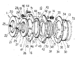
제2도는 제1도에 나타낸 축봉합장치의 분해 사시도.2 is an exploded perspective view of the shaft closure device shown in FIG.
* 도면의 주요부분에 대한 부호의 설명* Explanation of symbols for main parts of the drawings
(11) : 분할형 드라이브링 (12) : 원뿔형 시일링(11): Split drive ring 12: Conical seal ring
(13) : 교각형 슬리브 (14) : 조압(調壓) 스프링(13): Pierced sleeve (14): Pressure spring
(15) : 시일 슬리브 (16) : 프런트·프레스·플레이트(15): seal sleeve (16): front press plate
(17) : 분할형 환상 엔드시일 (18) : 조정나사(17): Split annular end seal (18): Adjustment screw
(20), (21) : 드라이브 링세그먼트 (22), (23) : 6각 구멍이 있는 나사(20), (21): Drive ring segment (22), (23): Hexagonal thread
(24) : 라이프핀 (26) : 테이퍼 접동면(摺動面)(24): life pin (26): tapered sliding surface
(27) : 환상의 끼워넣는 홈(環狀取入溝) (28) : 홈(窪)(27): annular insertion groove (28): groove
(29) : 링시일 (30) : 슬리브 부분(29): ring seal 30: sleeve portion
(31) : 스프링리테이닝플랜지 (32) : 환상홈(環狀溝)(31): spring retaining flange (32): annular groove
(33) : 0형 링 (34) : 헐럴한 구멍(33): type 0 ring (34): loose hole
(35) : 슬리브호울더 (44) : 나사(35): sleeve holder 44: screw
(46) : 나사구멍 (47) : 테이퍼 달린 내주면(46): screw hole (47): tapered inner peripheral surface
(49) : 스프링가이드플랜지(49): spring guide flange
(51) : 축방향 단면각형 환상 에지(軸方向斷面角形環狀 edge)(51): axial cross section of an annular edge
(60) : 양수기 (61) : 하우징60: water pump 61: housing
(62) : 스터핑그박스 (63) : 샤아프트(62): Stuffing Box (63): Shaft
본 발명은 유체기계, 유체기기 등의 유체장치에 사용되는 축봉합장치, 더욱 상세히 설명하면 봉합(seal)을 더욱 오래 사용할 수 있도록 하고 또 그 봉합의 교환을 용이하게 하여 광범위한 유체에 직용할 수 있도록하는 분할형 축봉장치에 관한 것이다.The present invention provides a shaft sealing device for use in a fluid device, such as a fluid machine, a fluid device, in more detail, so that the seal can be used longer, and the replacement of the seal can be facilitated so that it can be applied to a wide range of fluids It relates to a split shaft rod device.
좀래 이러한 좀류의 유체장치에 사용하여 온 축봉합장치에서는 패킹을 밀봉면에 축방향으로 밀어붙이고 그 패킹의 마모에 따라서 그 패킹을 축방향으로 조절하는 구조이므로 그 패킹은 항상 반경방향으로 팽창하는 경향에 있으며, 회전축은 그 패킹에 따라서 마모되며 특히 마모율이 커져서 그 대책으로 윤활성 및 냉각효과를 높여줄 필요가 있고 항상 일정한 누출(漏出)이 부득이하게 되고 그 위에 그 축봉합장치에서는 그 회전축의 흔들림으로 봉합성이 불안정하게 되는 경향에 있었다.In the axial sealing device which is used for the fluid device of these zombies, the packing is axially pushed to the sealing surface and the packing is axially adjusted according to the wear of the packing, so the packing always tends to expand in the radial direction. The rotating shaft is worn according to its packing. Especially, the wear rate is increased, so it is necessary to improve the lubricity and cooling effect as a countermeasure, and the constant leakage is always inevitable, and in the shaft sealing device, the rotating shaft is shaken. Suture tended to become unstable.
또 이런 종류의 축봉합장치는 유체장치의 스터핑박스에 배치하는 구조임으로 정기적으로 실시하게 되는 그라운드 조정 및 패킹 교환작업이 매우 까다로웠다.In addition, this type of shaft sealing device is arranged in the stuffing box of the fluid device, which is very difficult to adjust the grounding and packing that is performed regularly.
본 발명의 목적은 패킹을 접동면에 길들기 슨고 패킹의 봉합성을 향상하며 또한 패킹의 마모한계를 넓히고바꾸어 말하자면 패킹의 마모한계와 수명을 길게하고 회전하는 샤아프트의 진동을 흡수하면서 봉합상태를 유지하고 봉합압력을 과도히 크게하지 않고도 충분한 봉합을할 수 있게하여 유체장치를 구동하기 위한 동력을 경감하고 바꾸어 말하면 유체장치의 소비동력을 절약하여 나아가서 패킹의 마모량을 외부로부터 용이하게 보는 것을 가능하게 하고 패킹의 교화을 간단하게 하고 보수(保守) 관리를 간단하게 하며 그 위에 통상의 유체는 물론이고 연마성물질이나 그밖의 고형물을 함유한 매우 격렬한 유체에 이르는 넓은 범위의 유체에 사용할 수 있도록 하는 분할형 축봉장치를 제공함에 있다.It is an object of the present invention to improve the sealability of the packing by tamping the packing on the sliding surface and to expand and replace the wear limit of the packing, namely to increase the wear limit and life of the packing and to absorb the vibration of the rotating shaft. It is possible to maintain a sufficient seal without excessively increasing the sealing pressure, thereby reducing the power for driving the fluid device, in other words, to save the power consumption of the fluid device and to make it easier to see the amount of wear of the packing from the outside. Split type to simplify packing, simplify maintenance, and use on a wide range of fluids ranging from conventional fluids to highly aggressive fluids containing abrasive materials and other solids. In providing a shaft device.
그것들을 과제로서 본 발명의 분할형 축봉압장치는 유체장치의 하우징에 형성한 스터핑 박스(stuffing box)에서 바깥쪽으로 신장한 축의 일정한 위치에 고정하였으며 또한 그 스터핑박스를 면하는 드라이브핀(drive Pin)을 설비한 분할형 드라이브링과 그 스터핑박스를 면하는 테이퍼 접동면을 지니고 링시일을 게재하여 유동상태로 그 샤아프트에 끼워맞춰졌으며 또한 그 드라이브링에 수반되어 회전하도록 그 드라이브핀을 받아넣는 오목부를 마련한 원뿔형 시일·링그와 그 스터핑박스에 고정하였으며 또한 원주방향으로 적당한 간격을 두어서 여러개의 스프링호울더를 설비한 스프링리레이닝플랜지를 지니고 봉합하에서 그 스터팡박스에 끼워맞춰지는 고각형 슬리이브(abutment sleev)와 그 샤아프트의 축선방향으로 신축할 수 있도록하여 그 스프링호울더에 설치된 여러개의 조압(調壓)스프링관 그 원뿔형 시일·링을 면하도록 하여 그 샤아프트의 둘레에 그 조압 스프링을 받아넣는 여러개의 스프링가이드보오어(bore)를 형성한 스프링가이드 플랜지를 설비하고 또 그 샤아프트, 둘레에서 그 고각형 슬리이브에 봉합하에서 또한 유동상태에서 축방향으로 왕복 접동할 수 있도록 끼워지는 시일·슬리이브와 그 샤아프트의 둘레에서 그 스프링가이드플랜지에 지지 되었으며, 그 조압스프링을 위한 여러개의 조정나사를 마련한 프런트·프레스·플레이트와 그 프런트·플레이트를 게재하여 그 조압스프링으로 그 시일·링의 테이퍼 요동면에 밀어붙이는 환상시일·에지를 지니고또한 그 샤아프트의 둘레에서 그 프런트·트레스·플레이트에 장치한 분할형 환상엔드 ·시일 등으로 구성하는 것이다.Using them as a problem, the divided axial bar pressure device of the present invention is fixed at a fixed position of an axis extending outward from a stuffing box formed in a housing of a fluid device, and also a drive pin facing the stuffing box. Concave to insert the drive pin to be rotated with the drive ring by placing the ring seal with the tapered sliding surface facing the stuffing box and the split drive ring equipped with It is fixed to the conical seal, linkage and stuffing box, which is provided with a buoyant sleeve, and has a spring-relaying flange equipped with several spring holders with proper spacing in the circumferential direction and fits into the stuffing box under the seal. (abutment sleev) and the spring holder by allowing it to stretch in the axial direction of the shaft Spring guide flanges are provided with a plurality of spring guide borees, each of which is provided with a spring-loaded bore that receives the adjustment springs around the shaft and faces the conical seal rings. It was supported by the spring guide flange around the shaft, the seal and the sleeve being fitted to reciprocate in the axial direction under the flow of the shaft and around the solid sleeve at the periphery. The front press plate provided with a number of adjustment screws for the spring and the front plate are provided and have an annular seal and edge which is pushed to the tapered oscillation surface of the seal and the ring by the pressure spring, and around the shaft It consists of a split type annular end seal mounted on the front stress plate.
다음에 본 발명에 관한 분할형 축봉장치의 바람직한 구체예를 도면에 따라 설명한다.Next, a preferred specific example of the split shaft device according to the present invention will be described with reference to the drawings.
제1 및 제2도는 양수기(60)에 적용한 본 발명의 축봉장치의 구체예(10)를 보여주고 있다. 그 분할형 축봉합장치(10)는 분할형 드라이브링(11)과 원뿔형 시일·링(12)과 원주방향으로 적당한 간격을 두어서 3개의 스프링호울더(35)를 마련한 교각형 슬리브(13)와, 그 스프링호울더(35)에 장치된 3개의 스프링(14)과, 시일 슬리브(15)와 그들 조압 스프링(14)을 위한 3개의 조정나사(18)를 마련한 프런트·프레스·플레이트(16)와 분할형 환상엔드·시일(17) 등으로 구성되어 있다.1 and 2 show a specific example 10 of the shaft device of the present invention applied to a
그 분할형 드라이브·링(11)은 한개를 2개로 나눈 드라이브링 세그먼트(20),(21)로 되어있으며, 그 양수기(60)의 하우징(61)에 형성된 스터핑박스(62)에서 바깥쪽으로 신장된 샤아프트(63)의 일정한 위치에서 6각구멍이 있는 나사(22)(23)를 조여 붙쳐졌으며, 그 샤아프트(63)에 고정되어, 피 샤아프트(63)와 함께 일체적으로 회전되고 동시에 추력(thrust)을 받을 수 있도록 하고 있다.The split drive ring 11 consists of
그 드라이브·링(11)은 그 스터핑박스(62)를 면하는 드라이브핀(24)을 그 드라이브링세그먼트(20)의 링면에 돌출하게 하고 있다.The drive ring 11 causes the
그 원뿔형 시일·링(12)은 샤아프트보어(25)의 내경이 그 샤아프트(63)의 외경보다도 크게 뚫려져서·링시일(29)을 게재하여 유동상태에서 그 샤아프트(63)에 끼워맞출 수 있다. 그 시일·링(12)은 그 스터핑·박스(62)를 대면하는 링면에 테이퍼 접동면(26)을 형성하고, 그 드라이브·링(11)에 마주보는 링면에서 그 샤아프트·보어(25)의 개구면에 환상의 끼워넣는 홈(27)을 형성하고, 링·시일, 즉 링(29)을 끼워넣는 홈(27)에 받아넣을 수 있도록 가공되어 있다.The
나아가서 그 시일·링(12)은 그 드라이브링(11)에 마주보는 링면에 홈(28)을 형성하고 있다. 물론, 그 홈(28)은 그 드라이브핀(24)에 마주볼 수 있도록 그 시일·링(12)의 링면에 형성하고 그 링·시일(29)을 게재하여 그 샤아프트(63)에 끼워맞출 수 있을때, 그 드라이브·핀(24)의 선단부분을 받아넣고, 그 드라이브·링(11)에 수반되고, 그 위에 유동상태에서, 그 샤아프트(63)와 일체적으로 회전한다.Furthermore, the
그 교각형 슬리브(13)는 일체적으로 형성된 슬리브 부분(30)과 스프링 리테이닝 플랜지(Spring retaining flange)(31)에는 원주방향으로 같은 간격에서 3개의 헐거운 구멍(34)이 형성되었으며 그 결과, 그 스프링·리테이닝·플랜지(31)는 그 스터핑박스(62)의 당면(當面)에 첨부되었으며, 그 헐거운구멍(34)을 통하여 그 스터핑박스(62)의 나사구멍에 틀어넣는 나사(36)로서 그 단면에 죄어 붙쳐졌는데 그 교각형 술리브(13)를 그 스터핑박스(62)에 고정한다. 그 스프링· 리테이닝·플랜지(31)에는 그 나사(36)를 위한 헐거운 구멍(34)사이에서 플랜지면에 3개의 스프링호울더 (35)를 돌출하게 하고 있다.The
3개의 조압 스프링(14)은 코일·스프링으로 되어있으며, 그 스프링호울더(35)를 탄성적으로 죄어 붙이도록 대응하는 그 스프링호울더(35)에 1단을 끼워맞추고 그 샤아프트(63)의 중심을 나타내는 중심선 방향으로 신춘할 수 있어서 그 샤아프트(63)의 교각형 슬리브(13)의 스프링리테이닝플랜지(31)에 지지된다. 또 그 조압 스프링(14)은 타단에 스크루우시이트(37)를 고정하고 있다.The three
그 시일·슬리브(15)는 일체적으로 형성한 슬리브 부분(38)과 스프링·가이드·플랜지(39)로 구성되어있으며, 그 슬리브 단부의 외주면에는 환상홈(40)이 형성되었고. 그 환상홈(40)은 링(41)을 끼워넣고 있다. 따라서 그 시일 슬리브(15)가 그 슬리브 부분(38)을 그 교각형 슬리브(13)의 슬리브 부분(30)에 찔러넣도록 하여, 그 교가형 슬리브(13)에 짜서 맞출때, 그 시일 슬리브(15)의 슬리브(38) 부분과 그 교각형 슬리브(13)의 슬리브 부분(30)과의 사이의 간극은 그 0형링(41)에 따라서 시일하고 또 그 슬리브 부분(38)은 봉합하에서 그 위에 유동상태에서, 그 교각형 슬리브(13)내에 축방향으로 왕복 접동한다. 바꾸어 말하자면, 그 시일·슬리브(15)는 그 스터핑박스(62)내에 봉합하에서 그 위에 유동상태에서 축방향으로 왕복 접동한다.The
그 스프링가이드플랜지(39)는 그 원뿔형 시일·링(12)을 면하도록 하여 그 슬리브부분(38)의 다른편의 슬리브 단부에 일체가 되도록 형성하여 그 교각형 슬리브(13)의 스프링 · 리테이닝플랜지(13)에 형성한 3개의 스프링호울더(35)에 원주방향으로 맞추어진 간격으로 3개의 스프링, 가이드보어(42)를 마련하고 있다. 따라서 그 시일·슬리이브(15)가 그 교각형 슬리브(13)에 짜서 맞추어지면 그 스프링·가이드·플랜지(39)는 그 스프링리테이닝플랜지(31)의 스프링호울더(35)에 장치한 조압 스프링(14)을 그 스프링가이드보어(42)내에 축방향으로 신축할 수 있도록 각기 받아넣고 그들 조압스프링(14)을 안내하고 있다.The
또 그 스프링·가이드·플랜지(39)는 제1도로부터 이해할 수 있는 바와같이 테이퍼를 부착한 환상의 끼워 맞춘 단계(43)를 플랜지면에 형성하고 분합형 환상엔드시일(17)의 한편의 단면축을 끼워넣을 수 있도록 하고 있다.In addition, the
그 프런트·프레스·플레이트(16)는 그 샤아프트(63)의 둘레에 있어서 그 시일 ·슬리브(15)의 스프링가이드플랜지(39)에 맞추어지도록 링·플레이트에 형성되고 그 스프링·가이드·플랜지(39)에 틀어넣는 3개의 나사(44)에 장치되도록 3개의 헐거운 구멍(루우스 ·스크루우보어)(42)에 맞추어진 3개의 나사구멍(46)을 원주방향으로 같은 간격으로 형성하고 3개의 조정나사(18)를 각기 들어넣고 스크루우·시이트(37)를 게재하여 조압 스프링(14)의 스프링압(壓)을 바꿀 수 있도록 하고 있다.The
나아가서, 그 프런트·프레스·플레이트(16)는 제1도에서 이해할 수 있는 바와같이 테이퍼부착의 내주면(47)을 마련하고 그 분할형 환상엔드·시일(17)을 그 원뿔형 시일·링(12) 축으로 이탈 방지하면서 유지한다. 특히 그 내주면(47)이 그 엔드시일(17)을 끼워넣을때, 그 테이퍼 부착내주면(47)은 그 엔드시일(17)을 구성하고 엔드시일 세그먼트(48),(49)를 반경방향으로 눌러서 축소하고, 그들 엔드·시일 세그먼트(48),(49)의 맞부딧치는 면을 서로 밀어붙쳐서 맞부딧히는 면으로부터의 물이 새는 것을 저지한다.Furthermore, the
그 분할형 환상엔드·시일(17)은 석면사로 보강한 크레오솔수지, 카아본, 그래파이트(graphite)재(材), 브론즈베이스(bronze base)에 흑연을 스며들게 한 연한 재질등으로 되었으며 하나를 둘로 쪼갠 엔드·시일·세그먼트(48),(49)로 구성되었으며, 짜맞추는 것 및 분해하는 작업을 간단히 또한 용이하게 하고 있다.The split annular end seal (17) is made of creosol resin reinforced with asbestos yarn, carbon, graphite material, and a soft material in which graphite is imbedded in a bronze base. It consists of the split
그 엔드시일(17)은, 프런트·프레스·플레이트(16)의 테이퍼 부착 내주면(47)과 그 시일슬리브(15)의 테이퍼 부착환상의 끼워맞춘 홈(43)과 서로 보충적으로 끼워 맞추어지도록 축방향의 단면히 산형(山形)인 테이퍼 부착 의주면(50)을 마련하고, 그 프런트·프레스·플레이트(16)가 나사(44)로 시일·슬리브(15)의 스프링·가이드·플랜지(39)에 정치하게 되면 그 엔드·시일(17)은 그 시일·슬리브(15) 및 프런트·프레소·플레이트(16) 사이에 죄어 붙여져서 그것등에 고정되다.The
또 그 엔드·시일(17)은 제1도에서 이해하는 바와같이 축방향 단면각형 환상 에지(51)를 마련하고 최초에 원뿔형 시일·링(12)의 테이퍼 접동면(26)에 접초할때부터 긴밀한 시일면을 형성하면서 그 테이퍼 접동면(26)에 접축할 수 있게 하고 마모한계를 넓게하고 바꾸어 말하자면 마모한개를 길게 하고 즉 마모량을 크게 잡을 수 있도록 하여 자신의 수명을 길게 하고 있다.In addition, the
다음에 상술한 바와 같이 구성한 분할형 축봉합장치(10)를 양수기(60)에 짜서 맞추는 경우에 대하여 설명한다면 미리 0형링(33)을 환상홈(32)에 끼워넣고 스프링·리테이닝·플랜지(31)가 스터핑박스(62)의 단면에 첨가될때까지 슬리브부분(30)을 그 스터핑박스(62)안에 찔러넣고 나사(36)로 그 스프링 리테이닝플랜지(31)를 하우징(61)에 죄어 붙여, 그 교각형 슬리브(13)를 그 스터핑박스(62)에 고정한다. 이어서 그 스프링·리테이닝·플랜지(31)의 스프링·호울더(35)에 조압 스프링(14)을 장치한다. 그와같이 조압 스프링(14)이 그 스프링·스테이닝·플랜지(31)에 장치되었다면 나사(44)로 미리 조립한 시일·슬리브(15), 프런트·프레스·플레이트(16) 및 엔드시일(17)의 조립체를 그 샤아프트(63)의 둘레에 위치하도록 그 환상홈(40)에 0형링(41)을 끼워서 그 슬리브 부분(38)을 그 교각형 슬리브(13)에 찔러 넣는다.Next, the case where the split
다음에는 그 엔드시일(17)의 환상에지(51)에 테이퍼 접동면(26)을 접하도록 그 원뿔형 시일·링(12)을 샤아프트에 끼우고 다시금 그 샤아프트(63)에 0형링(29)을 끼우면서 그 원뿔형 시일·링(12)의 환상 끼워넣는 홈(27)에 끼워넣고, 그 원뿔형 시일 ·링(12)을 그 샤아프트(53)상에 유동상태로 지지하게 한다.Next, the
다음에 그 원뿔형 시일·링(12)의 홈(28)에 드라이브핀(24)을 찔러넣도록 하여 그 분할형 드라이브링(11)을 그 샤아프트(63)에 한쌍의 6각 구멍이 있는 나사(22), (23)로 죄어붙여 고정한다.Next, the
그와같이 하여 그 드라이브링(11)이 그 원뿔형 시일링(12)을 받을 수 있도록 하여 그 샤아프트(69) 위에 고정하였으면 3개의 조정나사(18)를 그 프런트·프레스·플레이트(37)를 게재하여 조압 스프링(14)을 밀어 붙이도록 하여 그 조정나사(18)를 그 나사구멍(46)에 탈아넣고 적당한 밀어붙이는 힘으로 그 엔드·시일(17)을 원뿔헝 시일·링(12)의 테이퍼 접동면(14)의 스프링압을 조정한다.Thus, when the drive ring 11 receives the
그와같이 하여 분할형 축봉합장치(10)는 양수기(60)의 스터핑박스(62)에 장치할 수 있다.In this way, the split
사용에 따라서 그 엔드·시일(17)이 마모하였다면 재차 조정나사(18)를 탈아넣고 조압 스프링(14)의 스프링압을 조정하면 충분하며, 그 결과 엔드시일(17)은 항상 최적의 시일상태로 유지된다. 또 그 엔드시일(17)의 마모량은 밖으로부터 용이하게 파악되며 보수관리가 매우 용이하게 된다. 나아가서 마모된 환상엔드·시일(17)의 교환은 나사(44)를 느슨하게 하여 프런트·프레스 ·플레이트(16)를 시일 슬리브(15)의 스프링가이드플랜지(39)에서 벗겨주므로서 간단 또한 용이하게 실시할 수 있다.If the
그와같이 하여 마모된 환상엔드·시일(17)의 교환작업은 분할형 드라이브링(11) 및 원뿔형 시일·링(12)을 샤아프트(63)에 벗겨지는 일이 없이 바꾸어 말하면 장치 전체를 분해하지 않고 간단히 실시할 수 있다.The replacement work of the
상술한 바에 의하여 이미 제안되었으며, 사용하여 오던 축봉합장치와 비교하여 말하면 본 발명의 분할형 축봉합장치가 분할형 드라이브링과 테이퍼 접동면을 마련하고 유체장치의 샤아프트에 시일하에서 그 위에 유동상태에서 끼워지게 되는 원뿔형 시일링과 그 유체장치의 샤아프트의 시일하에서, 더구나 유동상태에서 끼워지는 원뿔형 시일링과 그 유체장치의 스터핑 박스에 시일하에서 고정되며 또한 원주방향으로 적당한 간격을 두어서 여러개의 스프링호울더를 마련한 스프링리테이닝플랜지를 지닌 교각형 슬리브와 그 샤아프트의 축의 중심방향으로 신축할 수 있고, 그 스프링호울울로 장치한 여러개의 조압 스프링과, 그 조압 스프링을 받아넣는 여러개의 스프링가이드보어를 형성한 스프링가이드플랜지를 마련하고, 그 샤아프트의 둘레에서 그 교각형 슬리브에 시일하에서 또한 유동상태에서 축방향으로 접동할 수 있도록 끼을 수 있는 시일슬리브와 조압스프링을 위한 여러개의 조정나사를 구비한 프런트·프레스·플레이트를 게재하여 그 조정스프링으로 그 테이퍼 접동면에 밀어붙칠 수 있는 분할형 환상엔드 시일 등으로 구성되므로 본 발명의 분 할형 축봉합장치에서는 환상엔드·시일의 마모를 보정하는 곳의 추적기구를 마련하게 되며 그 환상엔드시일, 즉 패킹이 접동면에 익숙해지기 쉬워지고 그 패킹의 시일성이 향상되며 또한 그 패킹의 마모한계가 넓어져서 바꾸어 말하면 그 패킹의 마모한계가 길어지고 그 패킹의 수명이 길어지며 회전하는 샤아프트의 진동을 흡수하면서 시일상태가 유지되고 또 시일압을 과도하게 높이지 않아도 충분한 시일이 가능하게 되며 유체장치를 구동하기 위한 동력이 경감되고 바꾸어 말하자면, 그 유체장치의 소비동력이 절약되며 나아가서 그 패킹의 마모량 이외부로부터 용이하게 파악되어 그 패킹의 교환이 간단 또한 용이하게 되어 그 위에 통상의 유체는 물론 연마성물질이나 그밖의 고형물을 함유하는 좋지않은 유체에 이르는 넓은 범위의 유체에 안전하게 사용할 수 있도록 되며, 극히 실용성이 향상된다.Compared with the axial closure device which has already been proposed by the above, the split shaft sealing device of the present invention provides a split drive ring and tapered sliding surface and flows thereon under the seal on the shaft of the fluid device. Under the seal of the conical seal and the shaft of the fluid unit fitted in the conical seal, moreover, the conical seal ring fitted in the fluid state and the stuffing box of the fluid unit are fixed under the seal and spaced at a suitable interval in the circumferential direction. Pier type sleeves with spring retaining flanges provided with spring holders, which can be stretched in the direction of the center of the shaft of the shaft, several adjustment springs fitted with the spring holes, and several springs receiving the adjustment springs A spring guide flange with a guide bore is prepared, and around the shaft The piercing sleeve is provided with a front press plate with seal sleeves that can be fitted under the seal and axially slid in flow and with a plurality of adjustment screws for the adjustment springs and the tapered contact with the adjustment springs. The split shaft sealing device of the present invention is provided with a tracking mechanism for correcting the wear of the annular end and the seal, and the annular end seal, that is, the packing is in contact. It is easy to get used to hibernation, the sealability of the packing is improved, and the wear limit of the packing is widened. In other words, the wear limit of the packing is long, the life of the packing is long, and the seal absorbs vibration of the rotating shaft. The condition is maintained and sufficient sealing is possible without excessively increasing the seal pressure. In other words, the power consumption for the fluid device is reduced, in other words, the power consumption of the fluid device is saved, and furthermore, it is easily grasped from the wear amount of the packing, and the exchange of the packing is simple and easy, so that the ordinary fluid as well as the abrasive material thereon It can be used safely for a wide range of fluids, from bad fluids containing solids or other solids, and extremely practical.
Claims (1)
Applications Claiming Priority (3)
| Application Number | Priority Date | Filing Date | Title |
|---|---|---|---|
| JP58-50040 | 1983-03-25 | ||
| JP58050040A JPS59175676A (en) | 1983-03-25 | 1983-03-25 | Divided type shaft sealing device |
| JP???58-50040 | 1983-03-25 |
Publications (2)
| Publication Number | Publication Date |
|---|---|
| KR850000623A KR850000623A (en) | 1985-02-28 |
| KR860001695B1 true KR860001695B1 (en) | 1986-10-17 |
Family
ID=12847882
Family Applications (1)
| Application Number | Title | Priority Date | Filing Date |
|---|---|---|---|
| KR1019830001789A KR860001695B1 (en) | 1983-03-25 | 1983-04-27 | Seal |
Country Status (2)
| Country | Link |
|---|---|
| JP (1) | JPS59175676A (en) |
| KR (1) | KR860001695B1 (en) |
Families Citing this family (4)
| Publication number | Priority date | Publication date | Assignee | Title |
|---|---|---|---|---|
| JPS62180173A (en) * | 1986-02-03 | 1987-08-07 | Kansai Electric Power Co Inc:The | Shaft sealing device |
| US7677038B2 (en) | 1999-10-18 | 2010-03-16 | Kanzaki Kokyukoki Mfg. Co., Ltd. | Pump unit |
| US6425244B1 (en) | 1999-10-18 | 2002-07-30 | Kanzaki Kokyukoki Mfg. Co., Ltd. | Pump unit |
| US8001737B1 (en) * | 2007-12-18 | 2011-08-23 | Mhubbard 09, Llc | Corrugated deck sealing devices, apparatus, systems and methods of installation |
-
1983
- 1983-03-25 JP JP58050040A patent/JPS59175676A/en active Granted
- 1983-04-27 KR KR1019830001789A patent/KR860001695B1/en not_active IP Right Cessation
Also Published As
| Publication number | Publication date |
|---|---|
| KR850000623A (en) | 1985-02-28 |
| JPS59175676A (en) | 1984-10-04 |
| JPS6257864B2 (en) | 1987-12-03 |
Similar Documents
| Publication | Publication Date | Title |
|---|---|---|
| AU637232B2 (en) | Split mechanical face seal | |
| US5820129A (en) | Mechanical split double seals | |
| US6557856B1 (en) | Split mechanical face seal | |
| US4296952A (en) | Rotary joint | |
| US6109617A (en) | Gas seal assembly and method of sealing | |
| AU2005272129B2 (en) | Composite rotary seal assembly | |
| US4427204A (en) | Mechanical end face seal | |
| AU724735B2 (en) | A seal for a pump, and a pump comprising the seal | |
| EP1042626A1 (en) | Split mechanical face seal | |
| US6059293A (en) | Split mechanical face seal with seal face fluid introducing structure | |
| KR860001695B1 (en) | Seal | |
| US5642892A (en) | Gland seal assembly housing | |
| US3749412A (en) | Mechanical shaft seal | |
| US3054620A (en) | Gasket ring | |
| US5207794A (en) | Seal assembly for a shaft comprising a stuffing box | |
| EP0293431A4 (en) | Rotary seal. | |
| GB2046386A (en) | Liquid-tight rotary pipe joint | |
| US6017036A (en) | Mechanical shaft seal | |
| US11073212B1 (en) | Packing cartridge and method of installation | |
| US4363491A (en) | Shaft seal assembly | |
| US3311382A (en) | Stuffing box replacement seal | |
| US3811688A (en) | Mechanical seal for rotary shaft | |
| JP7246555B1 (en) | Bearing seal structure | |
| JP2003240125A (en) | Shaft sealing device | |
| CA2221477C (en) | Mechanical split double seals |
Legal Events
| Date | Code | Title | Description |
|---|---|---|---|
| A201 | Request for examination | ||
| G160 | Decision to publish patent application | ||
| E701 | Decision to grant or registration of patent right | ||
| GRNT | Written decision to grant | ||
| FPAY | Annual fee payment |
Payment date: 19911008 Year of fee payment: 6 |
|
| LAPS | Lapse due to unpaid annual fee |