KR860001397B1 - Balancer for use in centrifugal rotary machine - Google Patents
Balancer for use in centrifugal rotary machine Download PDFInfo
- Publication number
- KR860001397B1 KR860001397B1 KR8203852A KR820003852A KR860001397B1 KR 860001397 B1 KR860001397 B1 KR 860001397B1 KR 8203852 A KR8203852 A KR 8203852A KR 820003852 A KR820003852 A KR 820003852A KR 860001397 B1 KR860001397 B1 KR 860001397B1
- Authority
- KR
- South Korea
- Prior art keywords
- balancer
- liquid
- unbalance
- tub
- sphere
- Prior art date
Links
Images


Classifications
-
- D—TEXTILES; PAPER
- D06—TREATMENT OF TEXTILES OR THE LIKE; LAUNDERING; FLEXIBLE MATERIALS NOT OTHERWISE PROVIDED FOR
- D06F—LAUNDERING, DRYING, IRONING, PRESSING OR FOLDING TEXTILE ARTICLES
- D06F37/00—Details specific to washing machines covered by groups D06F21/00 - D06F25/00
- D06F37/20—Mountings, e.g. resilient mountings, for the rotary receptacle, motor, tub or casing; Preventing or damping vibrations
- D06F37/24—Mountings, e.g. resilient mountings, for the rotary receptacle, motor, tub or casing; Preventing or damping vibrations in machines with a receptacle rotating or oscillating about a vertical axis
- D06F37/245—Damping vibrations by displacing, supplying or ejecting a material, e.g. liquid, into or from counterbalancing pockets
-
- D—TEXTILES; PAPER
- D06—TREATMENT OF TEXTILES OR THE LIKE; LAUNDERING; FLEXIBLE MATERIALS NOT OTHERWISE PROVIDED FOR
- D06F—LAUNDERING, DRYING, IRONING, PRESSING OR FOLDING TEXTILE ARTICLES
- D06F37/00—Details specific to washing machines covered by groups D06F21/00 - D06F25/00
- D06F37/20—Mountings, e.g. resilient mountings, for the rotary receptacle, motor, tub or casing; Preventing or damping vibrations
- D06F37/24—Mountings, e.g. resilient mountings, for the rotary receptacle, motor, tub or casing; Preventing or damping vibrations in machines with a receptacle rotating or oscillating about a vertical axis
-
- F—MECHANICAL ENGINEERING; LIGHTING; HEATING; WEAPONS; BLASTING
- F16—ENGINEERING ELEMENTS AND UNITS; GENERAL MEASURES FOR PRODUCING AND MAINTAINING EFFECTIVE FUNCTIONING OF MACHINES OR INSTALLATIONS; THERMAL INSULATION IN GENERAL
- F16F—SPRINGS; SHOCK-ABSORBERS; MEANS FOR DAMPING VIBRATION
- F16F15/00—Suppression of vibrations in systems; Means or arrangements for avoiding or reducing out-of-balance forces, e.g. due to motion
- F16F15/32—Correcting- or balancing-weights or equivalent means for balancing rotating bodies, e.g. vehicle wheels
- F16F15/36—Correcting- or balancing-weights or equivalent means for balancing rotating bodies, e.g. vehicle wheels operating automatically, i.e. where, for a given amount of unbalance, there is movement of masses until balance is achieved
- F16F15/363—Correcting- or balancing-weights or equivalent means for balancing rotating bodies, e.g. vehicle wheels operating automatically, i.e. where, for a given amount of unbalance, there is movement of masses until balance is achieved using rolling bodies, e.g. balls free to move in a circumferential direction
-
- Y—GENERAL TAGGING OF NEW TECHNOLOGICAL DEVELOPMENTS; GENERAL TAGGING OF CROSS-SECTIONAL TECHNOLOGIES SPANNING OVER SEVERAL SECTIONS OF THE IPC; TECHNICAL SUBJECTS COVERED BY FORMER USPC CROSS-REFERENCE ART COLLECTIONS [XRACs] AND DIGESTS
- Y10—TECHNICAL SUBJECTS COVERED BY FORMER USPC
- Y10T—TECHNICAL SUBJECTS COVERED BY FORMER US CLASSIFICATION
- Y10T74/00—Machine element or mechanism
- Y10T74/21—Elements
- Y10T74/211—Eccentric
- Y10T74/2111—Plural, movable relative to each other [including ball[s]]
Landscapes
- Engineering & Computer Science (AREA)
- General Engineering & Computer Science (AREA)
- Textile Engineering (AREA)
- Physics & Mathematics (AREA)
- Acoustics & Sound (AREA)
- Aviation & Aerospace Engineering (AREA)
- Mechanical Engineering (AREA)
- Main Body Construction Of Washing Machines And Laundry Dryers (AREA)
- Centrifugal Separators (AREA)
Abstract
Description
제1도 내지 제6도는 종래 예를 설명하는 것으로서,1 to 6 illustrate a conventional example,
제1도는 탈수겸용 세탁기의 원리적 종단 측면도.1 is a principle longitudinal side view of a combined washing machine.
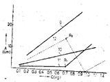
제2도는 보올밸런서 등에 의한 진동저감에 관한 특성도.2 is a characteristic diagram relating to vibration reduction by a bowl balancer and the like.
제3도는 작용설명을 위하여 회전조를 도해적으로 도시한 평면도.3 is a plan view schematically showing the rotating tub for explaining the operation.
제4도 및 제5도는 회전조를 각각 다른 상태로 도해적으로 도시한 측면도.4 and 5 are side views schematically showing the rotating tub in different states.
제6도는 종래의 보울밸런서의 실질적인 특성도.6 is a substantial characteristic diagram of a conventional bowl balancer.
제7도 내지 제9도는 본 발명의 한 실시예에 관한 것으로서,7 to 9 relate to an embodiment of the present invention,
제7도는 회전조의 밸런서 장착부의 확대종단 측면도.7 is an enlarged end side view of the balancer mounting portion of the rotating tub.
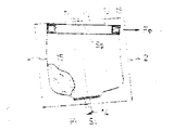
제8도는 밸런서의 절결평면도.8 is a cutaway plan view of the balancer.
제9도는 제2도에 상당한 도면.9 is a view corresponding to FIG.
* 도면의 주요부분에 대한 부호의 설명* Explanation of symbols for main parts of the drawings
20 : 회전조 22 : 밸런서20: rotating tank 22: balancer
23 : 환상케이스 24 : 환상실23: illusion case 24: illusion room
24b : 경사면 26 : 구체(추)24b: slope 26: sphere (weight)
27b : 돌부 W : 액체(식염수)27b: protrusion W: liquid (saline)
본 발명은 회전조가 그 내용물의 언밸런스 분포에 기언해서 이상진동하는 것을 방지하도록 되어 있는 원심회전기용 밸런서에 관한 것이다.The present invention relates to a balancer for a centrifugal rotor which is adapted to prevent the rotating tank from abnormally vibrating in view of the unbalance distribution of its contents.
종래에 예를들어 탈수겸용 세탁기에 있어서는 탈수시에 회전조가 세탁물의 언밸런스 분포에 기인하여 이상 진동하는 것을 규제하기 위해서 회전조에 밸런서를 설치한다. 이러한 밸런서로는 고체 밸런서, 액체 밸런서 및 보올밸런서의 세 종류가 있다. 이들 중 고체 밸런서는 회전조의 주위에 링 모양의 추를 장치해서 회전계의 관성 모멘트를 크게하여 진동 강제력을 상대적으로 저감시키도록 하는 것이다. 이에 대하여 액체 밸런서는 추로서 액체가 사용되고 또 보울밸런서는 추로서 강구, 즉 구체가 사용된다. 액체 밸런서는 액체를 유동이 자유롭게 봉함한 환상케이스를 회전조에 장착해서 구성되고 회전조가 공진회전수 이상으로 되면 액체가 세탁물의 편재 위치, 즉 언밸런스 부하위치와 반대 방향으로 이동해서 그 언밸런스를 흡수해서 진동 및 소음을 자동적으로 저감시킨다. 동일하게 보울밸런서에서는 구체가 상기 액체의 경우와 같이 이동하여 진동을 저감시킨다. 제2도는 상기 밸런서의 언밸런스양 Q와 진동진폭 A에 관한 특성을 제1도의 도시와 같은 탈수겸용 세탁기에 대하여 실측의 결과로서 도시한 것이다.Conventionally, for example, in a washing machine for dehydration combined use, a balancer is provided in the rotating tank to regulate that the rotating tank vibrates abnormally due to the unbalance distribution of the laundry. There are three kinds of such balancers: solid balancer, liquid balancer and bowl balancer. Among them, the solid balancer is provided with a ring-shaped weight around the rotary tub to increase the moment of inertia of the rotary system to relatively reduce the vibration forcing. In contrast, a liquid balancer uses liquid as a weight and a bowl balancer uses steel balls, that is, spheres. The liquid balancer is composed by mounting the annular case in which the liquid is freely flowed to the rotating tank. When the rotating tank is above the resonance speed, the liquid moves in the direction opposite to the uneven position of the laundry, that is, the unbalanced load position, and absorbs the unbalance to vibrate and Automatically reduce noise Likewise, in the bowl balancer, the sphere moves as in the case of the liquid to reduce vibration. FIG. 2 shows the characteristics of the unbalance amount Q and the vibration amplitude A of the balancer as a result of actual measurement with respect to the washing machine for dehydration combined use as shown in FIG.
제1도에 있어서 (1)은 외함이고 그 내부에는 타브(tub)(2)가 조봉(3)에 의하여 탄성적으로 매달리게 설치되고 이 타브(2)내에 탈수용 회전조(4)가 회전이 자유롭게 설치되며 그 내부에는 교반날개(5)가 설치된다. (6)은 동력전달기구(7)를 개재하여 회전조(4) 및 교반날개(5)에 회전력을 선택적으로 전달하기 위한 모우터, (8)은 회전조(4)의 상단 개구부에 설치된 이른바 밸런서이다. 제2도에서 상기 A는 타브(2)의 진동진폭, Q는 회전조(4)내의 세탁물의 편재로 인한 언밸런스양이고 (9)는 밸런서(8)를 고체 밸런서로 했을 때의 특성선, (10)은 액체 밸런서로 했을 때의 특성선, (11),(12)는 보울밸런서로 했을 때의 특성선이다. 특히 특성선(11)은 회전조(4)가 금속제등 변형되지 않는 구조의 경우를, 또 특성선(12)은 회전조(4)를 불가피하게 변형되는 플라스틱제로 했을 경우를 각각 도시한다. 제2도에서 특성선(12)를 생략하고 대비하면 진동저감 효과로서는 특성선(11)으로 표시되는 것과 같이 회전조(4)가 전혀 변형되지 않는다고 가정한 이상적인 구조일 때의 보울 밸런서가 가장 우수하고, 다음 이 액체 밸런서이다. 그러나 실제로는 회전조를 생산성이 우수한 플라스틱제로 하는 것이 일반적이기 때문에 보울밸런서를 적용해도 실제로 얻어지는 진동저감 효과는 특성선(12)과 같이 되어 액체 밸런서를 적용했을 경우보다도 떨어진다. 이 하 회전조(4)가 변형되는 경우의 현상에 대해서 제3도 내지 제5도를 상용해서 설명한다.In FIG. 1, (1) is an enclosure, and inside the tab (2) is installed so that it may be suspended elastically by the bar (3), and the dewatering rotary tank (4) in this tab (2) It is installed freely and the stirring blade 5 is installed therein. (6) is a motor for selectively transmitting rotational force to the rotating tank (4) and the stirring blade (5) via the power transmission mechanism (7), (8) is a so-called installed in the upper opening of the rotating tank (4) Balancer. In FIG. 2, A is an oscillation amplitude of the
제3도에는 회전조(4)와 이것에 설치한 보울밸런서(13)가 평면도로서 도해적으로 도시되고 제4도 및 제5도에는 탈수축(14)을 포함해서 플라스틱제 회전조(4)가 측면도로서 도해적으로 도시되고 있다. (15)는 언밸런스 부하(세탁물)이다. 제3도 및 제4도의 도시와 같이 세탁물의 언밸런스 분포상태로 회전조(4)가 공진회전수 이상의 예컨대 정상 회전하고 있는 경우에 구체(16)는 탈수축(14)의 중심(S1-S2 선)을 중심으로 해서 발생하는 원심력 F1과 회전중심(P1-P2 선)을 중심으로 해서 발생하는 원심력 F2을 동시에 받기 때문에 이들의 합력의 분력 Fb에 의해서 구체(16)는 언밸런스 부하(15)의 위치와는 반대측 방향으로 제3도의 중심점 P2와 S3가 일치되기까지, 즉 진동 진폭이 0으로 되기까지 언밸런스 부하(15)의 위치와 반대 방향으로 이동하여 그 언밸런스를 흡수하는 작용, 즉 진동 저감작용을 발휘한다. 그리고 모든 구체(16)가 서로 당접하도록 완전히 집합된 상태가 제2도 중 R1으로 도시한 언밸런스 흡수 한개점이고 그 이상의 언밸런스양의 증가에 대해서는 특성선(11)중 R1 다음의 선분과 같이 진동 진폭이 급증한다. 액체 밸런서의 경우도 상기와 같은 원리에 따라 액체의 이동이 발생해서 언밸런스의 흡수하도록 작용하나, 이 경우 보올 밸런서와는 달라서 실제적으로 진동진폭은 0이 되지 않는다. 그런데 회전조(4)가 플라스틱제이면 제4도에 도시한 것과 같이 변형과다. 즉 회전중심(P1-P2 선)과 보올 밸런서(13)의 탈수 방향 회전중심 S3이 일치되기까지 구체(16)가 집합되어 이때에 힘 Fb에 의해서 회전조(4)는 제4도중 △a 만큼만 변형된다. 그 결과 회전중심(P1-P2 선)과 탈수축중심(S1-S2 선)은 변형량△a 만큼의 변형이 생겨서 이 변형량이 본래 대략 0이 되는 이상적인 밸런서 효과를 악화시키는 원인이 되어, 진동저감 특성은 제2도중 특성선(12)으로 나타나게 된다. 따라서 언밸런스량이 증가하면 언밸런스 부하(15)와 반대 측으로 모이는 구체(16)의 양도 증가하여 한층 더 병형이 조장되어 진동저감 작용이 저하된다. 이러한 변형이 발생한 때도 제2도에 R2로 표시한 것과 같이 언밸런스 흡수 한계점은 존재하나 플라스틱제 회전조(4)의 경우에는 언밸런스 한계점 R2를 초과하도록 언밸런스 양이 증가해도 모든 구체(16)가 한계점 R2에서 이미 완전히 집합되어있으므로 힘 Fb의 증가는 없고 따라서 변형량 △a는 일정하게 된다. 그리고 한계점 R2 이상의 언밸런스 량에 의해서 발생하는 진동진폭은 그 위상이 상기 변형량 △a와는 180도 다르기 때문에 언밸런스량의 증가에 따라 제4도에 도시한 S2가 P2에 접근해서 결과적으로는 진동진폭이 0(제2도중 R3점)가 되고, 그리고 그 후에는 S2와 P2의 위치관계가 제5도의 도시와 같이 역전되어 진동 저감 작용은 제2도의 특성선(12)중, R3점 다음에 도시하는 것과 같이 되어 재차 진동이 증가하게 된다.FIG. 3 shows the rotating tank 4 and the bowl balancer 13 installed thereon in a plan view, and the plastic rotating tank 4 including the
이상의 설명에서 알수 있는 바와 같이 보올밸런서는 진동저감 효과에 있어서 가장 우수함에도 불구하고 회전조를 플라스틱제로 구성하면 그 변형에 의해 진동진폭은 언밸런스 흡수 한계점 R2에서 진폭 0까지 저하되기는 하나 그 저하가 급격하기 때문에 언밸런스 량의 약간의 증가에 의해서도 재차 증대되고 만다. 그리고 또 이러한 종류와 같은 탈수기에 있어서는 부하가 세탁물이기 때문에 언밸런스 부하의 양이 운전할 때마다 대폭적으로 변화하고 따라서 특성선(12)으로 도시되는 바와 같이 비교적 무거운 언밸런스 영역에서의 근소한 언밸런스량의 변화에 대해서 진동저감효과, 즉 언밸런스 흡수 효과가 대폭적으로 변화하는 특성의 것에서는 실제적인 사용에 있어서는 안정된 진동 및 소음저감 효과를 얻을 수 없게 된다.As can be seen from the above description, although the bowl balancer has the best vibration reduction effect, when the rotary tub is made of plastic, the vibration amplitude is reduced from the unbalance absorption limit point R2 to zero amplitude by the deformation, but the decrease is sharp. Therefore, even a slight increase in the unbalanced amount is increased again. In addition, in a dehydrator such as this type, since the load is laundry, the amount of unbalanced load changes drastically each time it is driven, and therefore, for a slight unbalanced amount change in a relatively heavy unbalanced region as shown by the characteristic line 12. When the vibration reduction effect, i.e., the characteristics of which the unbalance absorption effect changes drastically, it is impossible to obtain a stable vibration and noise reduction effect in practical use.
그러므로 본 발명은 회전조가 플라스틱제등 변형이 새기는 실제적 상황하에 있어서도 언밸런스량의 변화에 대한 언밸런스 흡수 효과의 변동 폭을 작게 할 수 있어 액체 밸런서 이상의 진동 저감 효과를 기대할 수 있고, 또한 이것을 극히 간단한 구성에 의해서 달성할 수 있는 원심회전기용 밸런서를 제공하는 것을 목적으로 한다.Therefore, the present invention can reduce the fluctuation range of the unbalance absorption effect against the change of the unbalance amount even under the actual situation where the rotating tank is made of plastic deformation such as plastic, so that the vibration reduction effect beyond the liquid balancer can be expected, and this is also in a very simple configuration. An object of the present invention is to provide a balancer for a centrifugal rotor that can be attained.
이하 본 발명을 탈수검용 세탁기에 적용한 한 실시예에 대하여 제7도 내지 제9도를 참조하여 설명한다. 제7도에서 (20)은 주벽에 다수의 탈수공(21)을 형성한 플라스틸제 회전조, (22)는 밸런서로서, 이들은 제1도의 회전조(4) 및 밸런서(8)를 대신한다. 회전조(20)는 주지와 같이 세탁시에는 세탁조로서 기능하고 탈수시에는 고속으로 회전되어 원심탈수조로서 기능한다. 그런데 밸런서(22)에 있어서 (23)은 내부를 환상실(24)로 구성한 환상케이스이고 이것의 상면 개구부는 내부에 액체 W와 복수개의 구페(26)를 유동 및 전동이 자유롭게 수용한 후 뚜껑부재(25)에 의해서 봉쇄된다.Hereinafter, an embodiment in which the present invention is applied to a washing machine for dehydration will be described with reference to FIGS. 7 to 9. In FIG. 7,
이러한 봉쇄는 예를들어 뚜껑부재(25)의 내면에 형성한 2줄의 감합홈(25a)을 환상케이스(23)의 개구주위에 접합해서 끼운다. 상기 환상케이스(23)내, 즉 환상실(24)내에는 복수개의 방해판(27)을 원주방향으로 등간격으로 간헐적으로 위치시키는 것과 같이 일체성형으로 형성한다. 이 방해판(27)은 환상실(24)내의 외측상부에 구체(26) 및 액체 W의 자유로운 이동로(24a)를 연속적으로 확보하기 위한 절결부(27a)를 형성하고 있고, 이 절결부(27a)를 제외한 각변이 환상실(24)의 4면에서 연속되는 형상을 이룬다. 이러한 방해판(27)에 있어서 특히 환상실(24)의 내저면으로 부터의 기립 부분의 낮은 쪽이 돌부(27b)로 되어 있다. 한편 환상실(24)내의 서로 대향하는 내측면중 외주벽의 내측면으로 내저면에서 기립해서 바깥쪽으로 경사지는 경사면(24b)을 형성하고, 또 이 경사면(24b)의 상종단(24c)을 이 위치에서 뚜껑부재(25)의 하면까지의 거리는 구체(26)의 반경을 넘는 위치로 설정되어 있다. 그리고 이 상종단(24c)의 상방영역은 수직면을 이루고 있다. 본 실시예에서 사용하는 전동이 자유로운 추로서의 구체(26)는 그 상호충돌에 의해 소음 및 녹이 나는 것을 방지하기 위해서 산화연 가루와 고무(합성수지도 된다)의 혼합재료로 형성한다. 또 이 구체(26)와 함께 동일 환상실(24)에 수용되는 액체 W는 액체 밸런서 기능을 발휘하기에 충분한 양으로 되고 이것을 위해서 환상실(24)내부가 완전히 충만되도록 하지 않고, 예를들면 돌부(27b)위의 공간의 중간에 액면이 오는 정도의 양을 설정한다. 특히 이 액체 W는 구체(26)의 자유로운 이동성을 저해하지 않는 낮은 점성의 것이 좋고, 따라서 물, 식염수 등 물을 기조로 하는 액체가 좋다. 본 실시예에서는 액체 W를 식염수로 하고 있다. (28)은 환상케이스(23)의 외주벽의 외측면에 일체로 성형한 수평으로 돌설된 플랜지이고, 이 플랜지(28)를 회전조(20)의 상단에 나사 등(도시 생략)으로 연결해서 상기 밸런서(22)를 회전조(20)의 상단 개구부의 내측에 동심배치 상태가 되도록 장착한다.In such a blockade, for example, two rows of
다음에 상기와 같이 구성한 밸런서(22)의 작용을 설명한다. 제9도는 제2도와 같이 밸런서(22)의 특성을 도시한 것으로 도면중 특성선(29)은 회전조(20)가 전혀 변형되지 않는 것으로 가정했을 때의 이론상의 특성을 나타내고, 또 특성선(30)은 플라스틱제의 변형되는 회전조(20)의 실제적인 특성을 나타내고 있다. 또 제9도에는 비교 대상으로서 제2도에 도시한 특성선(10) 및 (12)를 점선으로 나타났다. 이 밸런서(22)는 결론적으로 액체 W의 존재에 의해 액체 밸런서로서, 또 구체(26)의 존재에 의해 보올 밸러서로 각각 작용한다. 특히 언밸런스량이 제9도에 R11 또는 R12로 나타나는 언밸런스 흡수 한계점 이하에 있을 때는 주로 보울밸런서의 효과가 나타나고, 그 이상에서는 액체 밸런스 효과가 나타난다. 이하 그 동작에 대해서 설명한다. 회저조(20)를 탈수 운전하기 위해서 기동했을 때, 공진회전수 미만까지의 저속회전 기간에는 구체(26) 및 액체 W가 그다지 큰 원심력을 받지 않기 때문에 액체 W의 자유로운 원주 방향으로의 유동이 각 방해판(27)에 의해서 지지되고, 또 구체(26)의 방향판(27) 간격 이상의 자유로운 원주 방향으로의 이동이 돌부(27a)에 의해서 지지된다. 따라서 구체(26) 및 액체 W가 공진회전수 이하에서는 언밸런스 부하 위치방향으로 집합되어 그 언밸런스량을 조장하게 되는 결함을 방지할 수 있다. 그러나 회전조(20)가 공진회전수 이상에 도달하면 그동안에 구체(26) 및 액체 W가 돌부(27a)의 존재에 의하여 회전조(20)와 대략 일체로 회전할때까지 충분히 가속되어 있으므로 구체(26)는 원심력에 의해서 경사면(24b)을 올라가서 돌부(27b)보다도 높은 상종단(24c)에 위치한다. 이 위치에서 구체(26)의 상승력이 소실되기 때문에 구체(26)가 언제나 뚜껑부재(25)에서 이것을 위쪽으로 누르는 것처럼 당접하는 현상까지는 이르지 못하여, 뚜껑부재(25)에 쓸데없이 외력을 가하는 일은 없다. 이와같이 구체(26)는 전주에 걸쳐서 원주 방향으로의 이동이 저지되는 일이 없는 상기 이동로(24a)중에 위치되는 한편 액체 W도 원심력에 의해서 환상실(24)내의 외측에 집합되어서 이동로(24a)를 개재해서 원주방향으로의 이동이 가능해 진다. 그 결과 회전조(20)내에 언밸런스 부하가 존재했을 때는 구체(26) 및 액체 W가 그 언밸런스 부하 위치와는 반대측으로 집합한다. 이 경우 언밸런스량이 언밸런스 흡수 한계점 이하이면 구체(26)는 진동진폭이 0이 될 때까지 상호 접근하고 따라서 진폭이 0으로 되기 때문에 액체 W의 원주 방향의 이동은 발생하지 않고 주로 보올밸런서 효과가 나타난다. 이에대하여 언밸런스 부하가 언밸런스 흡수 한계점을 초과하고 있을 때는 이 한계점에서 모든 구체(26)가 이미 완전히 집합되어 있으므로 진동계로서는 언밸런스 상태에 있고, 이번에는 그 언밸런스를 흡수하는 방향으로 액체 W가 이동하여 액체 밸런서 효과가 발휘된다. 따라서 변형이 생기는 회전조(20)의 경우의 특성선(30)에 있어서 R12점 다음에서는 액체밸런스 효과에 의해서 제2도중 R2점 다음의 특성에 비해서 그 구배가 완만해지고 이것은 언밸런스량의 흡수 한계점을 초과하는 범위에서 언밸런스량의 변화에 대한 언밸런스 흡수 효과의 변동폭이 작아지는 것을 뜻한다. 회전조에 변형이 생기지 않는 경우에도 특성선(29)중 R11 다음의 선분과 같이 액체 밸런서의 특성선(10)과 평행이 되고, 제2도의 특성선(11)중 R1 다음의 부분에 도시되는 특성에 비래서 언밸런스 흡수 효과의 변동폭이 상당히 개선되어 있는 것을 알 수 있다. 동일한 이유에 의해서 특성으로 보았을 때 특성선(30)중의 R12 다음의 영역에서의 구배 자체는 액체 밸런서만의 특성선(10)과 대략 일치된다. 이상의 이유로 본 발명에서는 상기의 효과를 동일 환상실(24)내에 액체 W와 복수의 구체(26)를 봉입하기만 하는 극히 간단한 구성에 의해 달성되는 특징이 있다.Next, the operation of the balancer 22 configured as described above will be described. FIG. 9 shows the characteristics of the balancer 22 as shown in FIG. 2. The characteristic line 29 in the figure shows the theoretical characteristics when the rotating
다음에 본 실시예의 그밖의 특징에 대해서 설명한다.Next, other features of the present embodiment will be described.
일반적으로 보올밸런서에서는 구체가 단시간에 회전조와 일체회전 상태의 태세를 취하기 우해 고점도의 기름을 환상케이스내에 소량 봉입하고, 케이스 내면과 구체와의 사이의 점성 저항을 증대하도록 하낟. 그러나 이것으로는 회전조가 정상 회전중에 있을 때 구체가 상기와 같은 저항 때문에 이론상의 위치에는 집합되지 못하고, 또 집합정도가 우연성에 좌우되게 되어 제6도의 도시와 같이 동일한 언밸런스량 Q에 대한 진동진폭 A의 불균형이 켜지는 특성으로 되고 만다. 이것에 대하여 본 실시예에서는 액체 W로서는 특히 점성에 의한 효과를 기대하고 있지 않기 때문에 낮은 점성의 것도 좋고, 이것을 대신해서 환상실(24)의 저면에 형성한 돌부(27b)가 구체(26)에 회전력을 부여하는 작용을 하고 있기 때문에 동일 언밸런스량에 대한 진동진폭의 불균형이 적어서 이론치에 가까운 언밸런스 흡수 효과가 얻어지고, 또 반대로 돌부(27b)는 구체(26)의 과도한 전동성을 규제하기 때문에 회전조(20)의 기동시에 언밸런스 상태의 조장화를 저지하는 효과가 있다. 또 본 발명은 상기와 까은 탈수겸용 세탁기에만 한정되는 것이 아니고 원심회전기 전반에 적용이 가능한 것이다.In general, in a ball balancer, in order to make the sphere ready to rotate with the rotating tank in a short time, a small amount of high-viscosity oil is enclosed in the annular case to increase the viscous resistance between the inner surface of the case and the sphere. However, this means that when the tumbler is in normal rotation, the sphere cannot be gathered in the theoretical position due to the above resistance, and the degree of gathering depends on the coincidence, thus vibrating amplitude A for the same unbalance amount Q as shown in FIG. The imbalance of is turned on. On the other hand, in the present embodiment, since the liquid W does not particularly expect an effect due to viscosity, a low viscosity may be used, and instead, the protrusions 27b formed on the bottom surface of the
본 발명은 이상 상세히 설명한 바와 같이 회전조에 변형이 발생하지 않는 경우에는 물론, 변형이 발생하는 경우에도 동일 환상실 내에 낮은 점성의 액체와 전동이 자유로운 복수개의 추를 봉입하는 간단한 구성만으로 언밸런스량의 변화에 대한 언밸런스 흡수 효과의 변동폭을 작게할 수 있고, 액체 밸런서 이상의 진동 및 소음저감 효과를 기대할 수 있는 원심 회전기용 밸런서를 제공할 수 있다.As described in detail above, the present invention changes the unbalanced amount simply by encapsulating a low viscosity liquid and a plurality of freely driven weights in the same annular chamber, as well as when deformation does not occur in the rotating tank. It is possible to reduce the fluctuation range of the unbalance absorption effect on the liquid balancer, and to provide a balancer for a centrifugal rotor that can expect vibration and noise reduction effects over the liquid balancer.
Claims (3)
Applications Claiming Priority (3)
| Application Number | Priority Date | Filing Date | Title |
|---|---|---|---|
| JP56133628A JPS5836593A (en) | 1981-08-26 | 1981-08-26 | Balancer for centrifugal rotary machine |
| JP133628 | 1981-08-26 | ||
| JP56-133628 | 1981-08-26 |
Publications (2)
| Publication Number | Publication Date |
|---|---|
| KR840001288A KR840001288A (en) | 1984-04-30 |
| KR860001397B1 true KR860001397B1 (en) | 1986-09-22 |
Family
ID=15109257
Family Applications (1)
| Application Number | Title | Priority Date | Filing Date |
|---|---|---|---|
| KR8203852A KR860001397B1 (en) | 1981-08-26 | 1982-08-26 | Balancer for use in centrifugal rotary machine |
Country Status (5)
| Country | Link |
|---|---|
| US (1) | US4433592A (en) |
| JP (1) | JPS5836593A (en) |
| KR (1) | KR860001397B1 (en) |
| AU (1) | AU536938B2 (en) |
| GB (1) | GB2104553B (en) |
Cited By (1)
| Publication number | Priority date | Publication date | Assignee | Title |
|---|---|---|---|---|
| KR100434917B1 (en) * | 1996-07-19 | 2004-08-16 | 마쯔시다덴기산교 가부시키가이샤 | Balancer for disk drives |
Families Citing this family (49)
| Publication number | Priority date | Publication date | Assignee | Title |
|---|---|---|---|---|
| SE8304901D0 (en) * | 1983-09-13 | 1983-09-13 | Alfa Laval Separation Ab | DEVICE FOR BALANCING THE ROTOR WITH A Centrifugal Separator |
| US4583912A (en) * | 1984-03-16 | 1986-04-22 | Allis-Chalmers Corporation | Damped dynamic vibration absorber |
| US4646545A (en) * | 1985-04-26 | 1987-03-03 | Whirlpool Corporation | Balancing ring and attachment means for automatic washer |
| US4711610A (en) * | 1986-04-04 | 1987-12-08 | Machine Technology, Inc. | Balancing chuck |
| FR2625923B1 (en) * | 1988-01-18 | 1992-02-21 | Acutronic France Sa | AUTOMATIC BALANCING DEVICE OF A CENTRIFUGE IN OPERATION |
| US5845542A (en) * | 1992-05-21 | 1998-12-08 | Eti Technologies Inc. | Dynamic balancing method and apparatus |
| US5460017A (en) * | 1992-05-21 | 1995-10-24 | Eti Technologies Inc. | Weight compensating apparatus |
| US5605078A (en) * | 1992-05-21 | 1997-02-25 | Eti Technologies Inc. | Weight compensating method and apparatus |
| US5613408A (en) * | 1992-05-21 | 1997-03-25 | Eti Technologies Inc. | Weight compensating method and apparatus |
| US5724862A (en) * | 1992-05-21 | 1998-03-10 | Eti Technologies Inc. | Dynamic balancing method and apparatus |
| US5711190A (en) * | 1992-05-21 | 1998-01-27 | Eti Technologies Inc. | Weight compensating method and apparatus |
| KR970011122A (en) * | 1995-08-28 | 1997-03-27 | 김광호 | Balance of washing machine |
| JP2954031B2 (en) * | 1995-08-28 | 1999-09-27 | 三星電子株式会社 | Washing machine balance |
| KR100207022B1 (en) * | 1995-09-06 | 1999-07-01 | 김광호 | Balancer of a washer |
| JP2957144B2 (en) * | 1996-05-23 | 1999-10-04 | 三星電子株式会社 | Ball balancer for washing machine |
| JPH1043474A (en) * | 1996-05-29 | 1998-02-17 | Samsung Electron Co Ltd | Ball balancer |
| TW381135B (en) * | 1996-06-03 | 2000-02-01 | Samsung Electronics Co Ltd | Washing machine with ball balancer |
| US6535475B1 (en) * | 1996-10-09 | 2003-03-18 | Samsung Electronics Co., Ltd. | Disk player, and turntable incorporating self-compensating dynamic balancer, clamper incorporating self-compensating dynamic balancer and spindle motor incorporating self-compensating dynamic balancer adopted for disk player |
| JP3713884B2 (en) * | 1996-11-08 | 2005-11-09 | 日立工機株式会社 | Ball balancer and centrifuge equipped with ball balancer |
| US5857360A (en) * | 1997-01-08 | 1999-01-12 | Samsung Electronics Co., Ltd. | Washing machine having a balancing apparatus employing movable balls |
| KR100274470B1 (en) * | 1997-05-20 | 2000-12-15 | 구자홍 | A method of detecting eccentricity in washing machine and control apparatus thereof |
| KR100285523B1 (en) * | 1997-10-09 | 2001-04-02 | 구자홍 | Automatic balancing device of rotor |
| AU3020799A (en) * | 1998-03-27 | 1999-10-18 | Eti Technologies Inc | Balancing device usable in washing machines |
| SE520327C2 (en) * | 1998-10-19 | 2003-06-24 | Skf Autobalance Systems Ab | Method of pre-balancing a rotating drum having a temporally varying imbalance |
| US6442782B1 (en) | 2000-04-27 | 2002-09-03 | Maytag Corporation | Ball balancing mechanism |
| US6578225B2 (en) | 2000-05-25 | 2003-06-17 | Skf Autobalance Systems Ab | Low-speed prebalancing for washing machines |
| GB0211706D0 (en) * | 2002-05-22 | 2002-07-03 | Dyson Ltd | Automatic balancing device |
| CN100378368C (en) | 2002-05-22 | 2008-04-02 | 戴森技术有限公司 | Automatic balancing device |
| GB2410750A (en) * | 2004-02-05 | 2005-08-10 | Dyson Ltd | Automatic balancing device |
| US7232017B2 (en) * | 2004-04-01 | 2007-06-19 | Kearney-National Inc. | Pole vibration damping assembly and method |
| GB2420350A (en) * | 2004-11-17 | 2006-05-24 | Dyson Technology Ltd | Automatic balancing device |
| KR101273587B1 (en) | 2006-06-01 | 2013-06-11 | 삼성전자주식회사 | Drum type washing machine |
| EP2354292B1 (en) | 2006-06-01 | 2018-04-11 | Samsung Electronics Co., Ltd. | Washing machine having balancer |
| KR101003352B1 (en) * | 2006-06-01 | 2010-12-23 | 삼성전자주식회사 | Clothes Washing Machine Having Balancer |
| KR101267334B1 (en) * | 2006-11-06 | 2013-05-23 | 삼성전자주식회사 | Ball balancer Control Method of Washing Machine |
| KR100960068B1 (en) | 2006-11-10 | 2010-05-31 | 삼성전자주식회사 | Ball Balancer and Washing Machine Having the same |
| KR101356645B1 (en) * | 2007-04-19 | 2014-02-03 | 삼성전자주식회사 | Balancer and Drum type washing machine having the same |
| US8349242B2 (en) * | 2008-02-22 | 2013-01-08 | Vandor Corporation | Method of molding reel flanges and tool arrangement thereof |
| KR100974525B1 (en) * | 2008-07-09 | 2010-08-10 | 주식회사 한랩 | Automatic Balancing Centrifuge Using Balancer |
| KR101537590B1 (en) * | 2008-08-06 | 2015-07-22 | 엘지전자 주식회사 | Ball balancer and Washing machine having the same |
| KR101548994B1 (en) * | 2008-08-06 | 2015-09-01 | 엘지전자 주식회사 | Ball balancer and washing machne having the same |
| KR101039173B1 (en) * | 2008-09-18 | 2011-06-03 | 현대중공업 주식회사 | A valve control Method of four-stroke diesel engines |
| US8516885B1 (en) | 2009-01-12 | 2013-08-27 | Doug Fortune | Rotating object dynamic balancing system and method |
| MX2009002329A (en) * | 2009-02-27 | 2010-03-23 | Mabe Sa De Cv | Balance ring system in two planes for centrifugal rotation machines. |
| CA2677902A1 (en) * | 2009-08-25 | 2011-02-25 | Ryan J. Tanner | Balancer for a rotating object |
| US9163346B2 (en) | 2014-01-29 | 2015-10-20 | Alliance Laundry Systems, Llc | Washing machine control system and methods |
| CN109208251B (en) * | 2017-07-07 | 2021-03-02 | 青岛海尔洗衣机有限公司 | Washing machine |
| CN109594473B (en) * | 2018-12-24 | 2024-05-07 | 浙江工业大学 | Annular novel damper for inhibiting vibration of bridge stay cable |
| KR102568256B1 (en) | 2020-12-24 | 2023-08-22 | 전북대학교산학협력단 | Two-way drive root vegetable stripper |
Family Cites Families (4)
| Publication number | Priority date | Publication date | Assignee | Title |
|---|---|---|---|---|
| JPS5211148B2 (en) * | 1972-06-01 | 1977-03-29 | ||
| JPS5210696Y2 (en) * | 1972-06-20 | 1977-03-08 | ||
| JPS51115065A (en) * | 1975-04-01 | 1976-10-09 | Matsushita Electric Ind Co Ltd | Automatic balancing mechanism for hydroextractor |
| JPS55156682U (en) * | 1979-04-24 | 1980-11-11 |
-
1981
- 1981-08-26 JP JP56133628A patent/JPS5836593A/en active Granted
-
1982
- 1982-08-09 AU AU86988/82A patent/AU536938B2/en not_active Ceased
- 1982-08-16 GB GB08223533A patent/GB2104553B/en not_active Expired
- 1982-08-24 US US06/411,005 patent/US4433592A/en not_active Expired - Fee Related
- 1982-08-26 KR KR8203852A patent/KR860001397B1/en active
Cited By (1)
| Publication number | Priority date | Publication date | Assignee | Title |
|---|---|---|---|---|
| KR100434917B1 (en) * | 1996-07-19 | 2004-08-16 | 마쯔시다덴기산교 가부시키가이샤 | Balancer for disk drives |
Also Published As
| Publication number | Publication date |
|---|---|
| AU8698882A (en) | 1983-03-03 |
| AU536938B2 (en) | 1984-05-31 |
| GB2104553B (en) | 1985-02-27 |
| JPS5836593A (en) | 1983-03-03 |
| US4433592A (en) | 1984-02-28 |
| GB2104553A (en) | 1983-03-09 |
| JPS6326674B2 (en) | 1988-05-31 |
| KR840001288A (en) | 1984-04-30 |
Similar Documents
| Publication | Publication Date | Title |
|---|---|---|
| KR860001397B1 (en) | Balancer for use in centrifugal rotary machine | |
| US5916274A (en) | Reinforced ball balancer for clothes washing machine | |
| US2366236A (en) | Domestic appliance | |
| US3952557A (en) | Wobble washing machine | |
| SU463254A3 (en) | Centrifuge | |
| KR100513033B1 (en) | Washing machine with lower balancer | |
| US2976998A (en) | Damping system for a washing machine | |
| CA1111669A (en) | Suspension system for tub assembly in clothes washing machine | |
| US2758685A (en) | Agitating and spinning mechanism | |
| EP0810389A1 (en) | Balancing device | |
| US3783652A (en) | Washing machine | |
| US3494471A (en) | Balancing systems for centrifuging machines | |
| US2957331A (en) | Tub support | |
| US2405404A (en) | Domestic appliance | |
| US2836301A (en) | Tub structure | |
| JPS5837353A (en) | Balancer for centrifugal rotator | |
| US2836993A (en) | Washing machines | |
| US3049025A (en) | Energy absorption stop | |
| US3779090A (en) | Washing machine | |
| US3493118A (en) | Domestic appliance suspension | |
| US4403484A (en) | Dual node support assembly for washing machine | |
| US2519813A (en) | Extractor basket drive | |
| US6295678B1 (en) | Method for pre-balancing a rotating drum having a temporarily shifting unbalance | |
| US3116813A (en) | Vibration damping mechanism | |
| US4640105A (en) | Automatic washer suspension system |