KR860001055B1 - Apparatus and method for transferring a bingham solid through a long conduit - Google Patents
Apparatus and method for transferring a bingham solid through a long conduit Download PDFInfo
- Publication number
- KR860001055B1 KR860001055B1 KR1019830001911A KR830001911A KR860001055B1 KR 860001055 B1 KR860001055 B1 KR 860001055B1 KR 1019830001911 A KR1019830001911 A KR 1019830001911A KR 830001911 A KR830001911 A KR 830001911A KR 860001055 B1 KR860001055 B1 KR 860001055B1
- Authority
- KR
- South Korea
- Prior art keywords
- cylinder
- bingham
- conduit
- lubricant
- solid
- Prior art date
Links
- 239000007787 solid Substances 0.000 title claims abstract description 118
- 238000000034 method Methods 0.000 title claims description 26
- 230000008878 coupling Effects 0.000 claims abstract description 9
- 238000010168 coupling process Methods 0.000 claims abstract description 9
- 238000005859 coupling reaction Methods 0.000 claims abstract description 9
- 239000000314 lubricant Substances 0.000 claims description 96
- 239000002360 explosive Substances 0.000 claims description 38
- XLYOFNOQVPJJNP-UHFFFAOYSA-N water Substances O XLYOFNOQVPJJNP-UHFFFAOYSA-N 0.000 claims description 24
- 230000005484 gravity Effects 0.000 claims description 18
- 238000011144 upstream manufacturing Methods 0.000 claims description 13
- LYCAIKOWRPUZTN-UHFFFAOYSA-N Ethylene glycol Chemical compound OCCO LYCAIKOWRPUZTN-UHFFFAOYSA-N 0.000 claims description 12
- 238000002347 injection Methods 0.000 claims description 6
- 239000007924 injection Substances 0.000 claims description 6
- 239000003921 oil Substances 0.000 claims description 6
- 238000005553 drilling Methods 0.000 claims description 5
- 239000012530 fluid Substances 0.000 claims description 5
- 238000005422 blasting Methods 0.000 claims description 4
- 239000000203 mixture Substances 0.000 claims description 4
- 239000003129 oil well Substances 0.000 claims description 3
- 239000013535 sea water Substances 0.000 claims description 3
- 229920003169 water-soluble polymer Polymers 0.000 claims description 3
- 239000002245 particle Substances 0.000 claims description 2
- 150000003839 salts Chemical class 0.000 claims description 2
- 238000007789 sealing Methods 0.000 claims description 2
- 239000007762 w/o emulsion Substances 0.000 claims description 2
- 239000006193 liquid solution Substances 0.000 claims 2
- 239000010687 lubricating oil Substances 0.000 claims 2
- 239000003995 emulsifying agent Substances 0.000 claims 1
- 238000004806 packaging method and process Methods 0.000 claims 1
- 229910001220 stainless steel Inorganic materials 0.000 claims 1
- 239000010935 stainless steel Substances 0.000 claims 1
- 238000005086 pumping Methods 0.000 description 14
- 239000007788 liquid Substances 0.000 description 9
- 230000001050 lubricating effect Effects 0.000 description 9
- 239000000839 emulsion Substances 0.000 description 6
- 239000000499 gel Substances 0.000 description 6
- 229910052500 inorganic mineral Inorganic materials 0.000 description 4
- 239000011707 mineral Substances 0.000 description 4
- 235000010755 mineral Nutrition 0.000 description 4
- 229910000831 Steel Inorganic materials 0.000 description 3
- -1 for example Substances 0.000 description 3
- 239000000463 material Substances 0.000 description 3
- 238000005065 mining Methods 0.000 description 3
- 239000010959 steel Substances 0.000 description 3
- XEEYBQQBJWHFJM-UHFFFAOYSA-N Iron Chemical compound [Fe] XEEYBQQBJWHFJM-UHFFFAOYSA-N 0.000 description 2
- 230000015556 catabolic process Effects 0.000 description 2
- 238000002474 experimental method Methods 0.000 description 2
- 238000002156 mixing Methods 0.000 description 2
- 229920000642 polymer Polymers 0.000 description 2
- 238000003825 pressing Methods 0.000 description 2
- 230000035945 sensitivity Effects 0.000 description 2
- 235000002639 sodium chloride Nutrition 0.000 description 2
- SMZOUWXMTYCWNB-UHFFFAOYSA-N 2-(2-methoxy-5-methylphenyl)ethanamine Chemical compound COC1=CC=C(C)C=C1CCN SMZOUWXMTYCWNB-UHFFFAOYSA-N 0.000 description 1
- NIXOWILDQLNWCW-UHFFFAOYSA-N 2-Propenoic acid Natural products OC(=O)C=C NIXOWILDQLNWCW-UHFFFAOYSA-N 0.000 description 1
- HRPVXLWXLXDGHG-UHFFFAOYSA-N Acrylamide Chemical compound NC(=O)C=C HRPVXLWXLXDGHG-UHFFFAOYSA-N 0.000 description 1
- BVKZGUZCCUSVTD-UHFFFAOYSA-M Bicarbonate Chemical compound OC([O-])=O BVKZGUZCCUSVTD-UHFFFAOYSA-M 0.000 description 1
- ZAMOUSCENKQFHK-UHFFFAOYSA-N Chlorine atom Chemical compound [Cl] ZAMOUSCENKQFHK-UHFFFAOYSA-N 0.000 description 1
- RYGMFSIKBFXOCR-UHFFFAOYSA-N Copper Chemical compound [Cu] RYGMFSIKBFXOCR-UHFFFAOYSA-N 0.000 description 1
- 229920002907 Guar gum Polymers 0.000 description 1
- DGAQECJNVWCQMB-PUAWFVPOSA-M Ilexoside XXIX Chemical compound C[C@@H]1CC[C@@]2(CC[C@@]3(C(=CC[C@H]4[C@]3(CC[C@@H]5[C@@]4(CC[C@@H](C5(C)C)OS(=O)(=O)[O-])C)C)[C@@H]2[C@]1(C)O)C)C(=O)O[C@H]6[C@@H]([C@H]([C@@H]([C@H](O6)CO)O)O)O.[Na+] DGAQECJNVWCQMB-PUAWFVPOSA-M 0.000 description 1
- FYYHWMGAXLPEAU-UHFFFAOYSA-N Magnesium Chemical compound [Mg] FYYHWMGAXLPEAU-UHFFFAOYSA-N 0.000 description 1
- 229920003171 Poly (ethylene oxide) Polymers 0.000 description 1
- 239000004372 Polyvinyl alcohol Substances 0.000 description 1
- QAOWNCQODCNURD-UHFFFAOYSA-L Sulfate Chemical compound [O-]S([O-])(=O)=O QAOWNCQODCNURD-UHFFFAOYSA-L 0.000 description 1
- XSQUKJJJFZCRTK-UHFFFAOYSA-N Urea Chemical compound NC(N)=O XSQUKJJJFZCRTK-UHFFFAOYSA-N 0.000 description 1
- 239000000654 additive Substances 0.000 description 1
- 230000000996 additive effect Effects 0.000 description 1
- 229910001570 bauxite Inorganic materials 0.000 description 1
- 230000015572 biosynthetic process Effects 0.000 description 1
- 239000004202 carbamide Substances 0.000 description 1
- 239000003638 chemical reducing agent Substances 0.000 description 1
- 239000000460 chlorine Substances 0.000 description 1
- 229910052801 chlorine Inorganic materials 0.000 description 1
- 239000011248 coating agent Substances 0.000 description 1
- 238000000576 coating method Methods 0.000 description 1
- 229910052802 copper Inorganic materials 0.000 description 1
- 239000010949 copper Substances 0.000 description 1
- 239000010779 crude oil Substances 0.000 description 1
- 230000003247 decreasing effect Effects 0.000 description 1
- 230000001419 dependent effect Effects 0.000 description 1
- 238000010586 diagram Methods 0.000 description 1
- 239000002283 diesel fuel Substances 0.000 description 1
- 238000010790 dilution Methods 0.000 description 1
- 239000012895 dilution Substances 0.000 description 1
- 238000006073 displacement reaction Methods 0.000 description 1
- 238000009826 distribution Methods 0.000 description 1
- 239000003651 drinking water Substances 0.000 description 1
- 235000020188 drinking water Nutrition 0.000 description 1
- 230000000694 effects Effects 0.000 description 1
- 230000003628 erosive effect Effects 0.000 description 1
- 238000000605 extraction Methods 0.000 description 1
- 239000003337 fertilizer Substances 0.000 description 1
- 238000007667 floating Methods 0.000 description 1
- 230000008014 freezing Effects 0.000 description 1
- 238000007710 freezing Methods 0.000 description 1
- 150000004676 glycans Chemical class 0.000 description 1
- PCHJSUWPFVWCPO-UHFFFAOYSA-N gold Chemical compound [Au] PCHJSUWPFVWCPO-UHFFFAOYSA-N 0.000 description 1
- 229910052737 gold Inorganic materials 0.000 description 1
- 239000010931 gold Substances 0.000 description 1
- 239000000665 guar gum Substances 0.000 description 1
- 229960002154 guar gum Drugs 0.000 description 1
- 235000010417 guar gum Nutrition 0.000 description 1
- 229910052742 iron Inorganic materials 0.000 description 1
- 238000005461 lubrication Methods 0.000 description 1
- 239000011777 magnesium Substances 0.000 description 1
- 229910052749 magnesium Inorganic materials 0.000 description 1
- 238000002844 melting Methods 0.000 description 1
- 230000008018 melting Effects 0.000 description 1
- 239000012528 membrane Substances 0.000 description 1
- 239000008239 natural water Substances 0.000 description 1
- 230000003204 osmotic effect Effects 0.000 description 1
- 239000012466 permeate Substances 0.000 description 1
- 239000004033 plastic Substances 0.000 description 1
- 229920003023 plastic Polymers 0.000 description 1
- 229920001282 polysaccharide Polymers 0.000 description 1
- 239000005017 polysaccharide Substances 0.000 description 1
- 229920002451 polyvinyl alcohol Polymers 0.000 description 1
- 239000004576 sand Substances 0.000 description 1
- 229910052709 silver Inorganic materials 0.000 description 1
- 239000004332 silver Substances 0.000 description 1
- 239000000344 soap Substances 0.000 description 1
- 229910052708 sodium Inorganic materials 0.000 description 1
- 239000011734 sodium Substances 0.000 description 1
- RYYKJJJTJZKILX-UHFFFAOYSA-M sodium octadecanoate Chemical compound [Na+].CCCCCCCCCCCCCCCCCC([O-])=O RYYKJJJTJZKILX-UHFFFAOYSA-M 0.000 description 1
- 229940045870 sodium palmitate Drugs 0.000 description 1
- GGXKEBACDBNFAF-UHFFFAOYSA-M sodium;hexadecanoate Chemical compound [Na+].CCCCCCCCCCCCCCCC([O-])=O GGXKEBACDBNFAF-UHFFFAOYSA-M 0.000 description 1
- 239000007921 spray Substances 0.000 description 1
- 229910021653 sulphate ion Inorganic materials 0.000 description 1
- 239000000725 suspension Substances 0.000 description 1
- 230000009897 systematic effect Effects 0.000 description 1
- 239000012498 ultrapure water Substances 0.000 description 1
- 239000011345 viscous material Substances 0.000 description 1
Images


Classifications
-
- F—MECHANICAL ENGINEERING; LIGHTING; HEATING; WEAPONS; BLASTING
- F17—STORING OR DISTRIBUTING GASES OR LIQUIDS
- F17D—PIPE-LINE SYSTEMS; PIPE-LINES
- F17D1/00—Pipe-line systems
- F17D1/08—Pipe-line systems for liquids or viscous products
- F17D1/16—Facilitating the conveyance of liquids or effecting the conveyance of viscous products by modification of their viscosity
-
- F—MECHANICAL ENGINEERING; LIGHTING; HEATING; WEAPONS; BLASTING
- F16—ENGINEERING ELEMENTS AND UNITS; GENERAL MEASURES FOR PRODUCING AND MAINTAINING EFFECTIVE FUNCTIONING OF MACHINES OR INSTALLATIONS; THERMAL INSULATION IN GENERAL
- F16L—PIPES; JOINTS OR FITTINGS FOR PIPES; SUPPORTS FOR PIPES, CABLES OR PROTECTIVE TUBING; MEANS FOR THERMAL INSULATION IN GENERAL
- F16L41/00—Branching pipes; Joining pipes to walls
- F16L41/08—Joining pipes to walls or pipes, the joined pipe axis being perpendicular to the plane of the wall or to the axis of another pipe
-
- E—FIXED CONSTRUCTIONS
- E21—EARTH DRILLING; MINING
- E21B—EARTH DRILLING, e.g. DEEP DRILLING; OBTAINING OIL, GAS, WATER, SOLUBLE OR MELTABLE MATERIALS OR A SLURRY OF MINERALS FROM WELLS
- E21B43/00—Methods or apparatus for obtaining oil, gas, water, soluble or meltable materials or a slurry of minerals from wells
- E21B43/25—Methods for stimulating production
- E21B43/26—Methods for stimulating production by forming crevices or fractures
- E21B43/263—Methods for stimulating production by forming crevices or fractures using explosives
-
- F—MECHANICAL ENGINEERING; LIGHTING; HEATING; WEAPONS; BLASTING
- F15—FLUID-PRESSURE ACTUATORS; HYDRAULICS OR PNEUMATICS IN GENERAL
- F15D—FLUID DYNAMICS, i.e. METHODS OR MEANS FOR INFLUENCING THE FLOW OF GASES OR LIQUIDS
- F15D1/00—Influencing flow of fluids
- F15D1/02—Influencing flow of fluids in pipes or conduits
- F15D1/06—Influencing flow of fluids in pipes or conduits by influencing the boundary layer
-
- F—MECHANICAL ENGINEERING; LIGHTING; HEATING; WEAPONS; BLASTING
- F17—STORING OR DISTRIBUTING GASES OR LIQUIDS
- F17D—PIPE-LINE SYSTEMS; PIPE-LINES
- F17D1/00—Pipe-line systems
- F17D1/08—Pipe-line systems for liquids or viscous products
-
- Y—GENERAL TAGGING OF NEW TECHNOLOGICAL DEVELOPMENTS; GENERAL TAGGING OF CROSS-SECTIONAL TECHNOLOGIES SPANNING OVER SEVERAL SECTIONS OF THE IPC; TECHNICAL SUBJECTS COVERED BY FORMER USPC CROSS-REFERENCE ART COLLECTIONS [XRACs] AND DIGESTS
- Y10—TECHNICAL SUBJECTS COVERED BY FORMER USPC
- Y10T—TECHNICAL SUBJECTS COVERED BY FORMER US CLASSIFICATION
- Y10T137/00—Fluid handling
- Y10T137/0318—Processes
- Y10T137/0391—Affecting flow by the addition of material or energy
-
- Y—GENERAL TAGGING OF NEW TECHNOLOGICAL DEVELOPMENTS; GENERAL TAGGING OF CROSS-SECTIONAL TECHNOLOGIES SPANNING OVER SEVERAL SECTIONS OF THE IPC; TECHNICAL SUBJECTS COVERED BY FORMER USPC CROSS-REFERENCE ART COLLECTIONS [XRACs] AND DIGESTS
- Y10—TECHNICAL SUBJECTS COVERED BY FORMER USPC
- Y10T—TECHNICAL SUBJECTS COVERED BY FORMER US CLASSIFICATION
- Y10T137/00—Fluid handling
- Y10T137/8593—Systems
- Y10T137/87571—Multiple inlet with single outlet
- Y10T137/87587—Combining by aspiration
- Y10T137/87611—Flow control by varying position of a fluid inlet relative to entrainment chamber
Abstract
Description
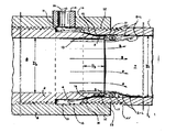
제 1 도는 본 발명에 의한 윤활제 주입기의 단면도.1 is a cross-sectional view of a lubricant injector according to the present invention.
제 2 도는 제 1 도에서 윤활제 주입부분에 대한 확대도.2 is an enlarged view of the lubricant injection portion in FIG.
제 3 도는 도관에서의 빙햄 고체와 윤활제의 흐름을 도시한 다이아그램.3 is a diagram illustrating the flow of Bingham solids and lubricant in the conduit.
* 도면의 주요부분에 대한 부호의 설명* Explanation of symbols for main parts of the drawings
1 : 제 1 실린더 2 : 제 2 실린더1: first cylinder 2: second cylinder
4 : 제 1 계단부 5 : 제 2 계단부4: first step part 5: second step part
6 : 제 3 실린더 11 : 환형실6: 3rd cylinder 11: annular chamber
12 : 나사 커플링 15 : 환형통로12: thread coupling 15: annular passage
16 : 목부 17 : 출구부16: neck 17: outlet
본 발명은 워터 겔 또는 유중수 유상액 형수성 폭발물이나 유압 분쇄법으로 유정을 자극하는데 사용하는 수성 조성물 등의 빙햄 고체를 긴 도관, 즉 파이프나 호스 드을 통하여 운반하는데 도움을 주는 장치와 그 장치를 사용하는 방법에 관한 것이다.The present invention provides a device and apparatus for assisting conveying Bingham solids, such as water gels or water-in-oil emulsions, or aqueous compositions used to stimulate oil wells by hydraulic crushing, through long conduits, ie pipes or hoses. It is about how to use.
종래에는 원유와 같이 점성이 큰 액체를 운반하는 도관에 점성이 작은 윤활액을 주입하여 도관내의 압력강하를 감소시키는 장치가 이용되고 있었다. 이와 같은 종래 기술은 여러 가지 장치를 사용하여 점성 낮은 액체를 도관에 주입하여 도관의 내벽과 도관을 흐르는 고점성 액체 사이에 환형막을 형성시키는 것이었다. 그 예로서 이. 지. 칠톤 등에 의해 허여된 미합중국 특허 제2,821,205호와 뱅크스톤등에 의해 허여된 제3,414,004호가 있다.Conventionally, an apparatus for reducing the pressure drop in a conduit by injecting a lubricating liquid with a low viscosity into a conduit carrying a highly viscous liquid such as crude oil has been used. This prior art has used various devices to inject a low viscosity liquid into the conduit to form an annular membrane between the inner wall of the conduit and the high viscosity liquid flowing through the conduit. As an example of this. G. US Patent No. 2,821,205 issued by Chilton et al. And US Pat. No. 3,414,004 issued by Bankston et al.
종래 기술에 대한 비슷한 예로서, 빙햄 고체 또는 온도에 따라 빙햄고체나 점성 유체로 되는 재료를 플러그 흐름(plug flow)상태로 운반하여 도관내에서 그 압력 강하를 감소시키는 장치가 있다. 그 대표적인 예로서 피. 알. 스코트 등에 허여된 미합중국 특허 제3,886,972호와 이.베르슈어에게 허여된 제3,826,279호 알. 에스. 올니에게 허여된 제4,273,147호 및 제이. 더블유. 브로킹톤에게 허여된 제4,259,977호가 있다. 상기한 예에서 마지막 두 예는 유상액 폭약인 빙햄 고체의 운반 및 그 배치에 관한 것이다.As a similar example to the prior art, there is a device for conveying bingham solids or viscous solids or viscous fluid material in a plug flow state to reduce its pressure drop in the conduit. As a representative example of that. egg. US Patent No. 3,886,972 to Scott et al. And US Pat. No. 3,826,279 to E. Berch. s. Nos. 4,273,147 and Jay to Olney. W. 4,259,977 to Brokenton. The last two examples in the above examples relate to the transport and placement of Bingham solids, an emulsion explosive.
여기에서 "빙햄 고체"란 긴 도관을 흐를 수 있는 물질로서, 일정한 입계값 이상의 전단 응력을 가한 후에야 지체없이 도관을 따라 흐를 수 있는 아교질 프라스틱 또는 반고체성 경점성 물질을 말한다. 그러나 이러한 성질을 가진 고체는 흐르기 시작하는 임계값 이하의 응력하에서도 일정시간이 지나면 점진적으로 변형될 수 있다.As used herein, "bingham solid" refers to a colloidal plastic or semi-solid hard viscous material that is capable of flowing long conduits and that can flow along the conduit without delay after shear stress above a certain threshold. However, solids with this property can gradually deform after a certain period of time, even under stresses that begin to flow.
이러한 빙햄 고체가 사용되는, 예로는 깊은 유정 또는 가스정에 빙햄 고체를 하향 주입하여 지층에 형성된 유압분열을 확장 추진함으로서 유정으로부터의 채취를 자극시키는 것이 있으며 도관의 압력 강하가 대단히 낮다면 가장 손쉽게 얻을 수있는 대단히 높은 송출량을 가지는 좋은 결과가 나타난다. 이러한 빙햄 고체는 균열부에 분해되면 유압분열이 완전히 봉쇄되는 것을 방지할 정도의 충분한 강도를 가진 경질제료(예를 들면, 모래, 소결보오크싸이트 및 호도껍질등)의 부유입자를 포함하는 겔화된 물(이하 워터겔이라 함)등으로 할 수도 있다.Such Bingham solids are used, for example, by deeply injecting Bingham solids into deep wells or gas wells to expand hydraulic propagation formed in the stratum to stimulate extraction from the wells, which is most easily achieved if the pressure drop in the conduit is very low. Good results with very high feed rates are obtained. These Bingham solids are gelled containing suspended particles of hard material (e.g. sand, sintered bauxite, and hododock shells) with sufficient strength to prevent complete breakdown of hydraulic breakdown when cracked. Or water (hereinafter referred to as water gel).
도관을 통하여 공급되는 물질이 빙햄 고체인 경우, 도관에 주입된 환형 액체막이 충분한 윤활작용을 하여 빙햄고체의 기둥이 큰 전단 변형이 없이 도관을 통하여 미끄러져 흐른다면, 즉 "플러그흐름"을 한다면 압력강하는 가장 효과적으로 감소된다. 이러한 윤활되는 플러그 흐름에 의하여 하향도관을 따라 빙햄 고체를 하향 운반하는 경우, 하향 도관에서의 플러그 흐름이 단지 중력만의 영향하에서 일어날 수 있으면 특히 유리하며 하향 도관에 있어서 중력만 작용하는 상태에서는 플러그 흐름을 얻기 위한 항력 저하 현상이 일어난다는 것 역시 장점이 된다.If the material supplied through the conduit is a Bingham solid, the annular liquid film injected into the conduit is sufficiently lubricated so that if the pillars of the Bingham solid slide through the conduit without large shear deformation, ie "plug flow", The drop is most effectively reduced. When the Bingham solids are transported downward along the downward conduit by this lubricated plug flow, it is particularly advantageous if the plug flow in the downward conduit can only occur under the influence of gravity and the plug flow in the gravity-only state in the downward conduit It is also an advantage that the drag drop occurs to obtain.
윤활제가 빙햄 고체와 혼합되지 않는 경우 많은 양의 윤활제를 사용하여 도관의 끝에서 윤활제를 걷어냄으로서 대부분 윤활제를 회수할 수 있고 윤활제가 빙햄 고체와 혼합되는 경우에도 윤활제에 의해 빙햄 고체가 희석되지만 그다지 심각한 문제가 되는 것은 아니다. 그러나 빙햄 고체가 시추공이나 유정에 주입되는 폭약일 경우 윤활제를 걷어낼 수 없고 특히 폭약의 강도와 감도를 효과적으로 유지하기 위해서는 가능한 적은 양의 윤활제를 사용하는 것이 좋다. 이에 대한 예로서 상기한 미합중국 특허 제,4259,977호의 방법에 사용되는 분무 링 장치에서는 윤활제의 유량을 폭약 유량의 3내지 5퍼센트(중량 퍼센트) 정도로 하는 것이 가장 효과적인 것으로 발표되었다. 상기 특허에 기술된 윤활제 주입기에서는 윤활제가 흐르는 환상 통로가 일정한 단면을 유지하므로 주입기 자체에서 윤활제의 흐름을 조절할 필요가 없다.If the lubricant does not mix with the Bingham solid, most of the lubricant can be recovered by removing the lubricant from the end of the conduit with a large amount of lubricant and even if the lubricant is mixed with the Bingham solid, the Bingham solid is diluted but not so much. This is not a serious problem. However, if the Bingham solid is explosives injected into boreholes or wells, the lubricant cannot be removed and it is advisable to use as little lubricant as possible to maintain the strength and sensitivity of the explosives effectively. As an example of this, the spray ring apparatus used in the above-mentioned method of US Pat. No. 4,259,977 has been found to be the most effective for the lubricant flow rate to be about 3 to 5 percent (weight percent) of the explosive flow rate. In the lubricant injector described in the patent, the annular passage through which the lubricant flows maintains a constant cross section so that the flow of the lubricant is not required to be adjusted in the injector itself.
또한 상기한 특허의 윤활제 주입기는 일반적으로 환상형 윤활제 흐름과 중력만에 의해 빙햄 고체가 하향 도관을 미끄러지게 하는 것이 아니며, 따라서 빙햄 고체가 갚은 구멍 아래로 공급될 경우에는 장점이 되지 못한다. 예를들면 전술한 미합중국 특허 제4,273,147호에 발표된 윤활제 주입기를 시용하여 직경 25.4mm의 호스를 통해 밀도 1.25의 유상액을 분당 27리터의 속도로 펌핑하는 실험을 행한 결과 압력 강하는 약 15.8kPa/m이었다. 중력에 의해서는 12.3kPa/m의 압력 강하가 일어나므로, 상기 특허의 장치는 중력만의 영향하에서 빙햄 고체를 상기 속도로 호스를 통해 미끄러지게 할 수 없으며 중력에 의해 빙햄 고체가 호스를 따라 움직일 것이라고 믿을 만한 근거가 없다.In addition, the lubricant injectors of the above patents generally do not cause the Bingham solids to slide down the conduit solely by the annular lubricant flow and gravity, and thus are not an advantage when the Bingham solids are fed under the hole being filled. For example, using a lubricant injector disclosed in U.S. Patent No. 4,273,147 described above, an experiment was conducted to pump an emulsion of 1.25 at a rate of 27 liters per minute through a 25.4 mm diameter hose, resulting in a pressure drop of approximately 15.8 kPa / m. Since gravity causes a pressure drop of 12.3 kPa / m, the device of this patent cannot slide Bingham solids through the hose at this speed under the influence of gravity, and gravity will cause the Bingham solids to move along the hose. There is no reason to believe.
부가적인 펌핑 압력없이 대단히 긴 길이의 하향 도관을 따라 빙햄 고체를 운반할 수 있는 윤활제 주입기는 중력만의 영향하에서 하향 도관을 따라 환형 윤활제 흐름에 의해 빙햄 고체를 미끄러지게 할 수 있는 것이어야 한다. 하향 도관이 호퍼의 출구에 있을 경우에는 펌핑 압력이 전혀 필요없다.A lubricant injector capable of transporting Bingham solids along very long lengths of downward conduits without additional pumping pressure should be capable of sliding the Bingham solids by an annular lubricant flow along the downward conduits under the influence of gravity alone. If the downward conduit is at the outlet of the hopper, no pumping pressure is required.
본 발명에 의한 장치는 폭발성 빙햄 고체의 펌핑에 있어서 종전 주입기에서 보다 적은 양의 윤활제를 시용하여 보다 큰 효과를 얻을 수 있는 윤활제 주입기이다. 예를들면 특허 제4,259,977호에 발표된 윤활제 주입기에 비하여, 본 발명에 의한 장치는 윤활제 유량이 폭발성 빙햄 고체의 유량의 0.33 중량 퍼센트 보다 크지 않을때, 중력만의 추진력 영향하에서 하향 도관 아랫쪽으로 윤활된 플러그 흐름을 발생시킨다. 이러한 낮은 항력하에서 상당히 긴 도관을 따라 이러한 폭약이 운송되며 필요한 펌핑 압력을 증가시키지 않고서도 대단히 깊은 수직 구멍으로 이러한 폭발성 빙햄 고체를 공급할 수 있다. 또한 폭발성 빙햄 고체에 사용되는 윤활제의 양이 10배 또는 그 이상 감소됨으로써, 폭약이 희석될 위험성이 감소되어 폭약의 강도나 감도의 조절이 용이하다. 더구나 윤활제가 흐르는 환형통로 출구에서 윤활제제의 바람직한 환형 와류가 형성된다.The apparatus according to the present invention is a lubricant injector which can achieve a greater effect by applying less lubricant in conventional injectors in the pumping of explosive Bingham solids. For example, compared to a lubricant injector disclosed in Patent No. 4,259,977, the device according to the present invention is lubricated under a downward conduit under the influence of gravity only propulsion when the lubricant flow rate is no greater than 0.33 weight percent of the flow rate of the explosive Bingham solid. Generate plug flow. Under such low drag, these explosives are transported along fairly long conduits and can supply these explosive Bingham solids into very deep vertical holes without increasing the required pumping pressure. In addition, the amount of lubricant used in the explosive Bingham solid is reduced by 10 times or more, thereby reducing the risk of dilution of the explosives, which makes it easy to control the strength or sensitivity of the explosive. Furthermore, the desired annular vortex of lubricant is formed at the outlet of the annular passage through which the lubricant flows.
본 발명의 목적은 세개의 실린더(제1, 제 2 및 제 3 실린더)로 구성되어 도관을 통과하는 윤활된 플러그 형태로 빙햄 고체를 운반할 수 있는 장치를 제공하기 위한 것이다. 제 1 실린더는 양쪽이 개방되어 있으며, 그 내경이 균일하다. 제 2 실린더는 양쪽이 개방되어 있으며 내경이 균일하나 제 1 실린더의 내경보다는 작고 한쪽에 끝 두개의 계단부가 형성되어 있는데 제 1 계단부는 제 1 실린더의 내경보다는 크고 외경보다는 작은 직경을 가지며, 제 2 계단은 제 2 실린더의 무디거나 또는 각진 말단 표면에 인접하고 제 1 실린더의 내경보다 작은 균일한 직경을 갖는다. 제 3 실린더는 양쪽이 개방되고 제 1 실린더와 제 2 실린더가 겹치는 부분에 연결되어 두 실린더를 유체 밀폐 및 강성 연결시킨다. 제 1 실린더와 제 2 실린더는 서로 동축상에 위치하며, 제 2 실린더 외표면에 형성된 제 2 계단부에 인접한 단부면이 이루는 평면으로 경계가 되는 동축상의 유체 유통된 제 1 및 제 2 원통실을 형성하고 있다. 제 2 실린더의 표면의 제 1 계단부와 이에 인접한 제 1 실린더의 말단 표면 및 제 3 실린더의 내표면의 일부가 제 1(하류) 및 제 2(상류) 원통실과 동축상에 있는 환형(윤활제 주입) 실을 형성한다. 동축 선상에서 제 1 실린더와 제 2 실린더의 상대적 위치는 나시 접합에 의해 제 3 실린더와의 결합부에서 조절할 수 있으므로, 제 2 실린더의 제 1 과 제 2 계단부 사이의 표면부가 제 1 실린더 한쪽끝이 마주보는 표면과의 접촉여하에 따라 환영실은 제 1 실린더에 개방될 수도 있고 폐쇄될 수도 있다. 접촉하지 않고 분리되는 경우에는 제 1 실린더와 환형실을 연결하는 환형 통로를 형성하며 이 통로는 환형실을 제한하는 평면 단부와 좁은 목부분과 그에 동축인 넓은 출구를 가지고 있으며, 제 2 실린더의 말단부는 빙햄 고체의 공급원에 연결된다. 제 3 실린더의 벽에는 외표면으로 부터 윤활액 공급원에 연결된 환형실까지의, 통로가 형성되어 있다. 제 1 실린더 말단부는 제 1 원통실에서 나오는 빙햄 고체와 윤활액을 받아 들이는 도관에 연결된다.It is an object of the present invention to provide an apparatus capable of conveying Bingham solids in the form of lubricated plugs consisting of three cylinders (first, second and third cylinders) passing through a conduit. The first cylinder is open at both sides, and its inner diameter is uniform. The second cylinder is open at both sides and has a uniform inner diameter, but smaller than the inner diameter of the first cylinder, and has two stepped ends formed at one side thereof. The first step portion has a diameter larger than the inner diameter of the first cylinder and smaller than the outer diameter, and the second The staircase has a uniform diameter adjacent the blunt or angled end surface of the second cylinder and smaller than the inner diameter of the first cylinder. The third cylinder is open at both sides and is connected to the overlapping portion of the first cylinder and the second cylinder to fluidly seal and rigidly connect the two cylinders. The first cylinder and the second cylinder are coaxial with each other, and define a coaxial fluid circulating first and second cylinder chamber bounded by a plane formed by an end surface adjacent to the second stepped portion formed on the outer surface of the second cylinder. Forming. Annular (lubricant injection) in which the first steps of the surface of the second cylinder, the distal surface of the first cylinder adjacent thereto and a portion of the inner surface of the third cylinder are coaxial with the first (downstream) and second (upstream) cylinder chambers. ) Form a thread. Since the relative position of the first cylinder and the second cylinder on the coaxial line can be adjusted at the engaging portion with the third cylinder by means of axial bonding, the surface portion between the first and second stepped portions of the second cylinder is one end of the first cylinder. Depending on contact with this opposing surface, the welcome chamber may be open or closed in the first cylinder. When disconnected without contact, they form an annular passageway connecting the first cylinder and the annular chamber, which has a planar end restricting the annular chamber, a narrow neck and a wide outlet coaxial to it, the distal end of the second cylinder. Is connected to a source of Bingham solids. The wall of the third cylinder is formed with a passageway from the outer surface to the annular chamber connected to the lubricating liquid supply source. The first cylinder end portion is connected to a Bingham solid and a conduit that receives the lubricating fluid from the first cylinder chamber.
환형실과 하류 원통실을 연결하는 환형통로 의좁은 목부분을 개폐 가능하게 하면서 축을 따라 제 1 및 제 2 실린더를 조절할 수 있으며 윤활제의 유동조건을 조절할 수 있다.It is possible to adjust the first and second cylinders along the axis and to control the flow conditions of the lubricant while allowing the narrow neck portion of the annular passage connecting the annular chamber and the downstream cylindrical chamber to be opened and closed.
본 발명에 의한 빙햄 고체의 운반 방법은,The conveying method of the Bingham solid by this invention,
거의 균일한 직경을 갖는 상류측(제 2)원통실을 통해 축방향으로 빙햄 고체를 가압하여 빙햄 고체를 상류측 원통실보다 큰 거의 균일한 직경을 갖는 하류측(제 1)원통실로 축방향으로 이동시키고 이를 하류측 원통실과 거의 같은 균일한 직경을 갖는 도관을 통하여 이동시키는 단계와,Pressing the Bingham solid in the axial direction through the upstream side (second) cylinder chamber having a substantially uniform diameter to axially move the Bingham solid into the downstream (first) cylinder chamber having a substantially uniform diameter larger than the upstream cylinder chamber. Moving and moving it through a conduit having a uniform diameter approximately equal to the downstream cylindrical chamber,
원통실에 동축이며 폭 조절 가능한 폭좁은 환형 목부와, 그 축에 직각이며 각 원통실을 구분하는 평면내에서 하류측의 대향단부가 되고 내경은 상류측 원통실 내경보다 약간 크고 외경은 하류측 원통실 내경과 거의 같은 보다 넓은 환형 출구부를 갖는 환형 통로에 의해 하류측 원통실에 연결되는 동축인 환형실을 통하여 윤활제를 동시에 주입하는 단계로 구성된다. 여기서 환형실과 도관을 통해 빙햄 고체가 가압되는 비율과 윤활제 주입비율 그리고 좁은 환형 목부의 폭은 중량을 기초로 한 빙햄 고체 유량의 약 5%이하의 윤활제 유량을 갖도록 그리고, 도관의 주여진 부분을 통하여 이동하는 빙햄 고체에 작용되는 항력은 도관의 주어진 부분이 수직일때 빙햄 고체의 자중에 의한 기동력 이하가 되도록 선택된다.Narrow annular neck coaxial with the cylinder and width-adjustable, and opposite ends on the downstream side in a plane separating each cylinder chamber, perpendicular to the axis, and having an inner diameter slightly larger than that of the upstream cylindrical chamber and having an outer diameter on the downstream cylinder. And simultaneously injecting lubricant through the coaxial annular chamber connected to the downstream cylindrical chamber by an annular passage having a wider annular outlet portion approximately equal to the inner diameter of the chamber. Where the rate at which Bingham solids are pressurized through the annular chamber and conduit, the lubricant injection rate, and the width of the narrow annular neck have a lubricant flow rate of less than about 5% of the Bingham solid flow rate based on weight, and through the main portion of the conduit The drag acting on the moving Bingham solid is chosen to be less than the maneuverable force of the Bingham solid when the given portion of the conduit is vertical.
제 1 도와 제 2 도에 도시되는 본 발명에 따른 윤활제 주입기에서는 두개의 실린더가 한쪽 실은 윤활제, 예를 들어 물등을 빙햄 고체 주위에 형성되는 직경 큰 하류 실로 주입하기 위한 환형 통로로부터 상류측이고, 다른 쪽 실은 하류측인 두개의 동심 원통실을 형성하는 연결 실린더 또는 슬리브에 의해 연결되어 워터겔 또는 유중수형 유상액 폭약등의 빙햄 고체를 가압 흐름 상태로 운반하도록 되어 있다.In the lubricant injector according to the invention shown in FIGS. 1 and 2, two cylinders are upstream from the annular passageway for injecting a single threaded lubricant, for example water, into a larger downstream chamber formed around a Bingham solid, The side chambers are connected by connecting cylinders or sleeves that form two concentric cylindrical chambers on the downstream side to carry Bingham solids such as water gels or water-in-oil emulsions in a pressurized flow state.
제 1 도 및 제 2 도에서, 1은 제 1 실린더, 2는 제 2 실린더이며, 이들은 각각 양단부가 개방되어 있고거의 균일한 내경을 가지며, 제 2 실린더(2)의 내경 D2는 제 1 실린더(1)의 내경 D1보다 작다. 한편, 제 2 실린더(2)의 외표면은 계단형으로 (직경이 축소된 상태로) 되어 있어서 제 1 계단부(4) 및 제 2 계단부(5)를 형성한다.In FIGS. 1 and 2, 1 is the first cylinder, 2 is the second cylinder, each of which is open at both ends and has a substantially uniform inner diameter, and the inner diameter D 2 of the second cylinder 2 is the first cylinder. the inner diameter of the (1) is less than D 1. On the other hand, the outer surface of the second cylinder 2 is stepped (with a reduced diameter) to form the first step 4 and the second step 5.
제 2 계단부(5)는 D1보다 작은 거의 균일한 직경을 가지며 각이진 제 2 실린더(2)의 단부면(3)에 인접하고 있다. 제 1 계단부(4)는 제 1 실린더(1)의 외경보다는 작으며 D1보다는 큰 직경을 갖는다.The second step 5 has an almost uniform diameter smaller than D 1 and is adjacent to the end face 3 of the angled second cylinder 2. The first step 4 is smaller than the outer diameter of the
제 1 실린더(1)의 양쪽끝 외표면에는 나사가 형성되어 있으며, 제 2 실린더(2)에는 한쪽끝과 제 1 계단부(4)의 인접부분에 나사가 형성되어 있다. 제 3 실린더(6)도 양끝이 개방되어 있고, 내벽에 나사가 없는 내표면(10)을 사이에 두고 제 1 나사부와 제 2 나사부가 형성되어 있다. 제 3 실린더(6)한쪽에 형성된 제 1 나사부는 제 1 실린더(1)의 한쪽 단부와 연결되며, 제 3 실린더(6)의 중간에 위치한 제 2 나사부는 제 2 실린더(2)의 제 1 계단부(4)에 인접한 나사에 연결된다. 이 세개의 실린더(1, 2, 6)는 나사 커플링(12)에 의해 동축으로 나사결합되어 있다. 제 2 계단부(5)에 의접한 제 2 실린더(2)의 말단표면(3)은 제 1 실린더(1)내측에 있고, 이로써 두 개의 동축 유통된 원통실(하류실(제 1) 원통실(7), 상류측(제 2) 원통실(8))을 형성하고, 원통 실측에서 수직인 단부면(3)을 통과하는 평면이 상하류측 원통실 사이의 경계가 된다.A screw is formed in the outer surface of both ends of the
제 2 실린더(2) 외표면의 제 1 계단부(4)와 제 1 실린더(1)의 단부면(9) 및 제 3 실린더(6)의 내표면(10)이, 제1, 제 2 원통실(7, 8)과 동축인 환형실(11)을 구성한다. 나사커플링(12)에 의해 제 1 실린더(1)와 제 2 실린더(2)의 상대적 변위, 즉 제 1 실린더(1)의 단부면(9)과 제 2 실린더(2)의 단부면(3)간의 거리 D3를 변화시킬 수 있다. 따라서 환형실(11)은 원통실에 도시한 바와 같이 개방될 수도 있고, 또 폐쇄될 수도 있다. 폐쇄된 상태에서는, 제 2 실린더(2)의 제 1 계단부(4)와 제 2 계단부(5)사이의 경사표면부(13)가 제 1 실린더(1)끝의 마주보는 표면인 대응표면부(14)와 접촉된다. 개방된 상태는 두 표면부(13, 14)가 분리되어 좁은 목부(16)와 넓은 출구부(17)를 가지며 원통실과 동축이고 두개의 원통실(7, 8)의 경계면에서 끝나는 환형통로(15)가 형성된다. 이리하여 목부(16)의 구멍이나 그 크기는 나사부(12)상에서 제 2 실린더(2)를 회전시켜 하류측 원통실에 대해 상류측 원통실(8)을 축방향으로 이동(제 1 실린더(1)에 대해 제 2 실린더(2)를 축방향으로 이동)시킴으로써 조절된다.The 1st step part 4 of the outer surface of the 2nd cylinder 2, the end surface 9 of the
윤활제 주입관(21)은 환형실(11)주위의 제 3 실린더(6)벽을 관통하는 구멍에서 제 3 실린더(6)와 나사 결합한다. 주입관(21)의 구멍은환형실(11)과 연통되며 그 부분에 통로(19)를 형성한다. 윤활제는 통로(19)를 통하여 환형실(11)로 펌핑할 수 있는데, 이 환형실(11)로부터 윤활제는 환형 통로(15)의 목부(16)를 통하여 흐를 수 있게 된다. 환형실(11)은 윤활제가 환형통로(15)를 통하여 주위방향으로 균일하게 흐르도록 허용한다.The lubricant injection pipe 21 is screwed with the third cylinder 6 at a hole passing through the wall of the third cylinder 6 around the annular chamber 11. The hole in the injection tube 21 communicates with the annular chamber 11 and forms a passage 19 in that portion. Lubricant may be pumped into the annular chamber 11 through the passage 19, from which the lubricant may flow through the neck 16 of the annular passage 15. The annular chamber 11 allows the lubricant to flow uniformly in the circumferential direction through the annular passage 15.
밀폐링(22)은 나사커플링(12)을 통해 윤활제가 손실되는 것을 방지하며, 고정나사(23)는 목부(16)폭을 예정대로 세팅하고 유지한다.The sealing ring 22 prevents the loss of lubricant through the screw coupling 12, and the set screw 23 sets and maintains the neck 16 width as scheduled.
제 2 실린더(2)와 제 3 실린더(6)의 외표면에는 목부(16)의 폭을 표시하는 눈금이 새겨져 있으며, 이는 또 적당한 유동방향, 즉 원통실(8)로부터 원통실(7)로 흐르는 방향을 지시하기도 한다.The outer surfaces of the second cylinder 3 and the third cylinder 6 are engraved with a scale indicating the width of the neck 16, which is also in the proper flow direction, ie from the cylinder chamber 8 to the cylinder chamber 7. It can also indicate the direction of flow.
제 2 실린더(2)의 말단부(18)의 외표면에 나사가 형성되어 있어 빙햄 고체의 공급원(즉 믹서나 탱크)에 연결된다. 제 1 실린더(1)의 말단부(20)에드 외표면에 나사가 형성되어 도관의 입구에 연결되도록 되어 있다. 윤활제 주입관(21)의 말단부(28)의 외표면에 형성된 나사는 윤활제의 공급원에 연결시키기 위한 것이다.A screw is formed on the outer surface of the distal end 18 of the second cylinder 2 to connect to a source of Bingham solids (ie a mixer or a tank). A screw is formed on the outer surface of the end portion 20 of the
제 3 도에 도시된 바와 같이 윤활제 펌프(24)에 의해 윤활제가 통로(19)를 통하여 주입기 내부로 공급되며, 여기서 윤활제는 펌프에 공급되는 에너지 또는 윤활제 공급 라인의 조절밸브(25)에 의해 압력 및 유량이 일부 조절되며, 이는 또 윤활제 주입기의 환형 통로(15)의 목부(16)의 폭을 변화시켜서도 일부 조절된다.As shown in FIG. 3, lubricant is supplied by the lubricant pump 24 through the passage 19 into the injector, where the lubricant is supplied by the control valve 25 of the lubricant supply line or energy supplied to the pump. And the flow rate is partially adjusted, which is also partially adjusted by varying the width of the neck 16 of the annular passage 15 of the lubricant injector.
목부(16)의 폭과 조절밸브(25)가 최적인 상태란, 펌프(27)에 의한 빙햄 고체 펌핑 압력이 만족스럽게 낮은 안정된 상태이거나, 도관(26)이 충만되어 있을때 펌프(27)에 의한 압력이 만족스럽게 낮은 간헐적인 상태이거나, 중력만의 영향하에 흐른다는 조건하에서 윤활제 흐름의 최저유량을 가지고 윤활제 주입기 및 도관(26)을 통하여 빙햄 고체를 만족스런 고유량으로 송출하는 상태를 말한다. 이런 상태는 빙햄 고체 및 윤활제의 성분, 펌프의 작동성능, 도관의 직경 및 길이, 그 길이에 따른 양정, 출구에서의 유체적역학적 외부 압력 및 온도에 어느 정도 의존하게 되어 있다.The optimum width of the neck 16 and the control valve 25 means that the Bingham solid pumping pressure by the pump 27 is satisfactorily low or when the conduit 26 is filled. A condition in which the Bingham solid is delivered at a satisfactory high flow rate through the lubricant injector and conduit 26 with a minimum flow rate of lubricant flow under conditions where the pressure is satisfactorily low or flows under the influence of gravity alone. This condition is to some extent dependent on the components of the Bingham solids and lubricants, the performance of the pump, the diameter and length of the conduit, the heading along its length, and the hydrodynamic external pressure and temperature at the outlet.
일반적으로 최적조건은 윤활제 제어 밸브를 열고 주입기 목부를 넓게 개방하고 그 개구를 차차 감소시켜서 성능을 제어함으로써 경험적으로 얻을 수 있다. 이런 실험은 짧은 도관으로 실험하는데는 빙햄 고체 시용량이 적어도 되므로 실제로 시용할 것 보다 약간 짧은 어느 정도의 길이를 갖는 도관으로 실험하는 것이 편리하다.In general, optimum conditions can be obtained empirically by controlling the performance by opening the lubricant control valve, opening the injector neck wide and gradually decreasing its opening. Such experiments require a small amount of Bingham solids to test with shorter conduits, so it is convenient to test with conduits with some length rather shorter than those actually used.
윤활 피막의 한쪽 면이 도관의 벽에 접촉하고, 다른 한면은 빙햄 고체에 접촉하고 있으므로, 도관을 따라 흐르는 윤활 피막의 평균 선속도는 빙햄 고체 선속도의 1/2이다. 윤활 피막이 자동적으로 상기와 같은 속도분포를 형성하므로 윤활제가 주입되는 지점에서 빙햄 고체가 침식됨으로서 일어나는 피막의 윤활성의 손실은 최소화된다. 제 2 도에 도시된 바와 같이 환형통로(15)의 출구에서는 윤활제가 환형 와류(AV)를 형성하기 때문에 위와 같은 현상이 일어난다. 이런 와류는 빙햄 고체 기둥의 움직임에 의해 형성되고, 그 회전속도는 빙햄 고체와 윤활제의 가장 인접한 두개의 유선(B=L)의 속도와 항상 일치하게 된다. 이러한 와류가 형성되는 것은 환형 통로(15)의 출구부(17)가 축방향으로 향하고, 제 2 계단부(5)에 인접한 단부면(3)이 두 흐름이 접촉하기 전에 두 흐름간에 격막으로서 작용하고, 목부(16)를 통한 윤활제의 유속이 빙햄 고체의 유속의 1/2 이하이기 때문이다. 윤활제의 바람직한 유속에 대한 상한점은 다음 조건으로 주어진다.Since one side of the lubricating film is in contact with the wall of the conduit and the other side is in contact with the Bingham solid, the average linear velocity of the lubricating film flowing along the conduit is 1/2 of the Bingham solid linear velocity. Since the lubricating film automatically forms the above velocity distribution, the loss of lubricity of the film caused by the erosion of Bingham solids at the point where the lubricant is injected is minimized. As shown in FIG. 2, the above phenomenon occurs because the lubricant forms an annular vortex AV at the outlet of the annular passage 15. This vortex is formed by the movement of the Bingham solid column, and its rotational speed always matches the speed of the two closest streamlines (B = L) of Bingham solid and lubricant. The formation of this vortex is such that the outlet 17 of the annular passage 15 is axially oriented and the end face 3 adjacent the second step 5 acts as a diaphragm between the two flows before the two flows contact. This is because the flow rate of the lubricant through the neck 16 is 1/2 or less of the flow rate of the Bingham solid. The upper limit for the desired flow rate of the lubricant is given by the following conditions.

F1: 윤활제의 체적유속F 1 : Volumetric flow rate of lubricant
F2: 빙햄 고체의 체적유속F 2 : Volumetric flow rate of Bingham solids
W : 환형 통로 목부의 폭W: width of annular passage neck
D : 도관의 내경D: inner diameter of conduit
이와 같은 관계는 주어진 유속에 대해 환형 통로 목부의 폭에 대한 하한점도 다음 식으로 정의해 준다.This relationship also defines the lower limit for the width of the annular passage neck for a given flow rate.

동시에 윤활제의 피먁을 주위 방향으로 균일하게 얻는데 필요한 조건은 환형 통로 목부를 통한 압력 강하가 충분해서 윤활제 주입기 한쪽면에서의 윤활제 공급도관의 위치 같이 불균일한 인자에도 불구하고 주위방향으로 균일한 윤활제층을 제공하고, 빙햄 고체 기둥의 유속단면에서의 공란 및 윤활제와 빙햄 고체간의 밀도 차이로 인한 부력을 제공하는 것이다. 충분한 압력 강하를 얻으려면 환형 통로의 목부폭에 바람직한 상한점이 있어야만 한다.At the same time, the condition necessary to obtain the lubricant pitch uniformly in the circumferential direction is that the pressure drop through the annular passage neck is sufficient to produce a uniform layer of lubricant in the circumferential direction despite the uneven factors such as the position of the lubricant supply conduit on one side of the lubricant injector. And buoyancy due to gaps in the flow velocity cross section of the Bingham solid column and the difference in density between the lubricant and the Bingham solid. To achieve a sufficient pressure drop, the neck width of the annular passage must have a desirable upper limit.
목부폭의 상한점과 하한점 사이에는 최적 또는 거의 최적 성능을 발휘하는 목부 폭의 범위가 되며, 주입기에 공급되는 윤활제의 유속이 충분한 윤활작용을 일으킬 수 있다면, 과도한 윤활제의 공급은 윤활제에 의해 빙햄 고체가 희석되는 바람직하지 못한 결과를 초래한다. 이에 관련되는 여러가지 변수로는 윤활제의 체적 펌핑속도(F1), 윤활제 조절 밸브의 구멍면적(AV), 환형 목부의 폭(At), 도관내 빙햄 고체의 체적유속(F2), 도관에서의 빙햄 고체의 압력강하(P2)가 있다.Between the upper and lower limits of the neck width, there is a range of neck widths that exhibits optimal or nearly optimal performance, and if the flow rate of the lubricant supplied to the injector can cause sufficient lubrication, the supply of excess lubricant is supplied by the lubricant to Bingham This results in undesirable consequences where the solid is diluted. Several variables related to this are: volumetric pumping speed of the lubricant (F 1 ), hole area (AV) of the lubricant control valve, width of the annular neck (At), volumetric flow rate of Bingham solids in the conduit (F 2 ), There is a pressure drop (P 2 ) of the Bingham solid.
바람직한 가동 상태란 주위환경에 따르지만, F2는 가능한 크고, P2는 가능한 낮으며, F1/F2값이 가능한 작아 빙햄 고체와 윤활제의 혼합을 최소로 줄일 수 있어야 한다. F1/F2값이 증가함에 따라 F2증가하려하고, P2는 감소하려 하므로 절충된 값이 요구된다. 일반적으로 At와 F1=F1(AV)의 결정은 시행 착오법이나 체계적인 실험을 통해 성능면에서 상기한 절충 값을 얻을 수 있다.Preferred operating conditions depend on the environment, but F 2 should be as large as possible, P 2 as low as possible, and F 1 / F 2 values as small as possible to minimize the mixing of Bingham solids and lubricants. As F 1 / F 2 increases, F 2 tries to increase and P 2 tries to decrease, so a compromise is required. In general, the determination of At and F 1 = F 1 (AV) can be obtained through the trial-and-error method or systematic experimentation.
본 발명에 의한 장치가 긴 도관을 따라 빙햄 고체를 운반할 목적으로 시용될 경우, 요구되는 펌핑 압력이 줄어들거나 빙햄 고체의 유속이 증가된다. 본 발명에 따르면, 최소한 직경이 300mm(이는 불균일 또는 비원형 단면을 가진 도관의 최소 직경이다)인 도관을 따라 빙햄 고체를 운반할 때의 저항력은 도관내의 빙햄 고체 중앙 기둥 주위에 저점성액(예를들면 물)의 환형층이 형성되므로 감소된다. 특히 중력만의 영향하에서 도관하향부를 따라 빙햄 고체가 플러그 흐름 형태로 미끄러져 내려갈 수 있을 정도로 저항력이 감소된다.When the device according to the invention is used for the purpose of conveying Bingham solids along long conduits, the required pumping pressure is reduced or the flow rate of Bingham solids is increased. According to the present invention, the resistance when transporting Bingham solids along a conduit with a diameter of at least 300 mm (which is the minimum diameter of a conduit with a non-uniform or non-circular cross section) is characterized by low viscosity (e.g. For example, an annular layer of water is formed and therefore reduced. In particular, under the influence of gravity alone, the resistance is reduced to the extent that Bingham solids can slide down in the form of plug flows along the conduit down.
본 발명에 의한 장치가 시용되는 한가지 예는 긴도관 특히 하향 도관을 갖는 파이프나 호스 등의 긴 도관을 통하여 빙햄 고체인 워터겔 또는 유중수형 유상액 형태의 액체 폭약을 운반하는 것이다. 이 경우 도관은 고정 믹서나 탱크로부터 폭약이 채워질 용기 또는 이동식 탱크까지 연장되거나, 또는 이동식 탱크나 믹서로부터 폭파시킬 지층의 하나 또는 그 이상의 시추구멍 바닥까지 폭약을 장입할 수 있도록 연장한다.One example in which the device according to the invention is used is to convey liquid explosives in the form of Bingham solid watergels or water-in-oil emulsions through long conduits such as pipes or hoses having long conduits, in particular downward conduits. In this case, the conduit extends from the fixed mixer or tank to the vessel or mobile tank to be filled with the explosive, or from the mobile tank or mixer to the bottom of one or more boreholes of the strata to be blown up.
예를들면 굴착, 채광, 채석 또는 탄성파 탐사 작업에서 시추구멍은 수십미터 길이를 가질 수 있고, 채광작업에서 깊이 묻힌 광석을 처음 발파시키고 체취해 낼때나 수원(water well), 유정, 가스웰 또는 온천등을 폭발적으로 자극시킬 때의 시추공은 그 깊이가 수천 미터에 달할 수도 있다.For example, in drilling, mining, quarrying, or seismic exploration operations, the drilling holes may be several tens of meters in length, and the first time blasting and extracting deeply buried ores in a mining operation, or in water wells, oil wells, gas wells or hot springs. Boreholes that explode on the back can reach thousands of meters deep.
구멍의 칼라는 지표면에 있을 수도 있고, 지하 채광지 또는 늪이나 바다 깊이에 해당하는 물 속에 있을 수도 있다. 이동식 탱크나 믹서는 탱크 트럭이나 트레일러, 수륙양용차, 짐배, 선박 또는 잠수함에 의해 폭약을 장입하기 편리한 곳으로 운반된다.The color of the hole may be on the earth's surface, or it may be in underground mining or in water corresponding to the depth of a swamp or sea. Mobile tanks or mixers are transported to tanks, trailers, amphibians, barges, ships or submarines where they can be conveniently loaded with explosives.
도관을 통하여 흐르는 빙햄 고체는 도관내를 통하여 빙햄 고체를 가압하의 탱크로 가스나 유체와 함께 주입하던가 탱크의 도관의 입구 사이에 설치된 펌프에 의해 가압하면 흐름이 촉진된다. 대단히 가파르게 설치된 도관 부분을 따라 하향 유동하는 빙햄 고체는 중력에 의해 추진되지만, 압력을 가하거나 도관내로 빙햄 고체를 펌핑함으로서 더움 촉진시킬 수도 있다.Bingham solids flowing through the conduit flow through the conduit to inject the Bingham solid with gas or fluid into the tank under pressure, or pressurized by a pump installed between the inlet of the conduit of the tank. Bingham solids that flow downward along a very steeply installed conduit portion are propelled by gravity, but may also be promoted by applying pressure or pumping Bingham solids into the conduit.
본 발명에 의한 빙햄 고체의 운송 방법은 빙햄 고체가 윤활제 영향을 받을 정도로 혼합되지 않고 도관의 내벽과 중심부 빙햄 고체의 기둥 사이에 얇고 균일한 윤활제 피막을 형성시키는 것이다. (1) 도관의 수직 또는 급경사부에서 중력만에 의해 추진되거나 또는 (2) 전도관이 이 펌핑압에서 또는 호스 차열압에서 얻는 최대 펌핑 압력 보다 훨씬 작은 펌핑 압력으로 추진되거나, (3) 펌핑이 잠시 중단된 후 다시 가동되었을때 빙햄 고체 기둥이 어느 정도의 속도(예를들어 내경 50mm 도관에서 분당 170리터)로 움직이도록 할 수 있는 최소 값으로 윤활 피막의 두께가 조절되어야 한다.The method for transporting Bingham solids according to the present invention is to form a thin and uniform lubricant coating between the inner wall of the conduit and the pillars of the central Bingham solid without mixing the Bingham solids to the extent that they are lubricated. (1) the propulsion by gravity alone at the vertical or steep slopes of the conduit; or (2) the conduction pipe is propelled at a pumping pressure much less than the maximum pumping pressure obtained at this pumping pressure or at the hose heat shielding pressure, or (3) When stopped and restarted, the thickness of the lubricating film should be adjusted to the minimum value that will allow the Bingham solid column to move at a certain speed (eg 170 liters per minute in a 50 mm inner conduit).
일반적으로 윤활 피막의 두께는 도관의 대부분이 깊은 구멍 또는 바다 밑에 거의 수직 또는 급경사 설치되어 있을 때는 상기(1)의 조건이 도관의 대부분이 수평 또는 거의 수평으로 설치되어 있을 때는 상기(2)의 조건이 빙햄 고체가 도관에 체류하는 동안 윤활제 피막의 파열을 빙햄 고체가 흡수할 경우에는 상기(3)의 조건이 맞게 되다.In general, the thickness of the lubricating film is the condition of (1) above when most of the conduit is installed vertically or steeply below the deep hole or the sea. When the Bingham solid absorbs the rupture of the lubricant film while the Bingham solid stays in the conduit, the condition of (3) is met.
윤활제는 비교적 낮은 점성도를 가져 빙햄 고체 구조에 급작스럽게 침식하지 않도록 하여야 하지만 빙햄 고체와 혼합되지 않아야 하는 것은 아니다. 따라서 0℃ 이상에서, 물은 충분히 높은 항복 강도를 갖는 빙햄 고체인 워터겔형 폭약 또는 유중수형 유상액 폭약에 대한 윤활제로서 적절한 것이 된다. 한편 디젤 연료는 워터겔형 폭약에 대한 윤활제는 될 수 있지만 일반적으로 유중수형 유상액 폭약에 대한 윤활제로는 그 구조를 급격히 침식하므로 적절하지 못하다. 또, 이는 윤활 피막의 두께나 점성도를 급격히 변화시킬 가능성이 있기 때문이다.Lubricants should have a relatively low viscosity so that they do not abruptly erode into the Bingham solid structure but are not to be mixed with Bingham solids. Therefore, above 0 ° C., water is suitable as a lubricant for water gel explosives or water-in-oil emulsions which are Bingham solids with sufficiently high yield strength. Diesel fuels, on the other hand, can be lubricants for water-gel explosives, but they are generally not suitable as lubricants for water-in-oil explosives. This is because there is a possibility that the thickness and viscosity of the lubricating film can be changed rapidly.
윤활제로서 물을 사용하는 경우, 추운 날씨에 빙점을 강하시키거나 빙햄 고체가 도관에 체류하는 동안 삼투현상에 의해 상당량의 윤활제가 빙햄 고체에 흡수 될때 그 증기압을 낮추기 위해 (그리하여 삼투현상에 의한 흡수 경향을 줄이기 위해) 에틸렌 글리코올이나 우레아 등의 철가제를 사용해도 좋다. 윤활제로 사용되는 물은 순도가 높거나 식수용일 필요는 없다. 그러므로 현장에서 쉽게 얻을 수 있는 즉 냇물, 우물물, 용해되지 않은 염분을 함유하는 바닷물 등 나트륨, 마그네슘, 철, 염소, 황산염, 중탄산염 등이 함유된 자연수를 사용하고 마찰 감소제를 통해 물에 첨가할 수도 있다. 즉 마찰 감소용 첨가제로서 물이 연성일 경우는 예를들어 스테아린산 나트륨, 팔미트산나트륨 등의 비누나 또는 수용성 중합체 예를들어 아크릴 아미드와 아크릴산 또는 폴리사카리드, 무코사카리드, 폴리비닐 알콜, 또는 폴리에틸렌옥시드등의 중합체나 혼성 중합체 같은 것을 사용할 수도 있다.When water is used as a lubricant, it is necessary to lower the freezing point in cold weather or to reduce the vapor pressure when a significant amount of lubricant is absorbed into the Bingham solid by osmosis while the Bingham solid stays in the conduit (and thus tends to be absorbed by the osmotic phenomenon). In order to reduce the risk of these problems, you may use a fertilizer such as ethylene glycol or urea. The water used as a lubricant does not have to be high purity or drinking water. Therefore, natural water containing sodium, magnesium, iron, chlorine, sulphate, bicarbonate, etc., which can be easily obtained on-site, such as streams, wells, and sea salts containing undissolved salts, may be added to the water through friction reducers. have. That is, when water is soft as a friction reducing additive, for example, soaps such as sodium stearate and sodium palmitate, or water-soluble polymers such as acrylamide and acrylic acid or polysaccharide, mucosaccharide, polyvinyl alcohol, or Polymers, such as polyethylene oxide, and hybrid polymers can also be used.
빙햄 고체의 항복 강도는 충분한 펌핑 속도를 얻을 수 있도록 충분히 낮아야 하나 윤활제와 혼합되어서는 안되며, 보통 1 내지 3kPa 정도가 바람직하다.The yield strength of the Bingham solid should be low enough to achieve a sufficient pumping speed but should not be mixed with the lubricant, usually on the order of 1 to 3 kPa.
다음은 본 발명에 의한 윤활제 주입기가 사용되는 여러가지 실시예를 기술한 것이다.The following describes various embodiments in which a lubricant injector according to the present invention is used.
[실시예 1]Example 1
직경 51mm, 길이 61m 도관(26)의 첫 30.5m는 릴축이 수평인 호스릴로 감겨 있고, 나머지 30.5m는 지면에 수평하게 놓여 있다.The first 30.5 m of the 51 mm diameter and 61 m long conduit 26 is wound with a hose reel with a horizontal reel axis, while the other 30.5 m lies horizontally on the ground.
사용된 빙햄 고체는 유중수 유상액형 액체 폭약이며 항복 강도는 2kPa, 밀도는 1.32g/cm3이다. 윤활제로는 물을 사용하였다. 윤활제 주입기의 환형 목부(16)의 폭은 완전히 밀폐된 상태에서 1cm당 4.53개의 나사가 형성되어 있는 나사 커플링(12)의 실린더를 1/3회전 후진시켜 형성한다. 목부분은 나사축에 대해 20°경사져 있으므로, 목부분의 폭은 [1/3회전×(4.53나사/cm)-1]×sin 20°=0.25mm이고, 그 단면적은 0.025cm×5.08cm×π=0.41cm2이다. (5.08cm는 51mm 도관의 유효직경)The Bingham solid used is a water-in-oil emulsion liquid explosive with a yield strength of 2 kPa and a density of 1.32 g / cm 3 . Water was used as a lubricant. The width of the annular neck 16 of the lubricant injector is formed by one third rotation of the cylinder of the threaded coupling 12 having 4.53 screws per cm in a fully closed state. Since the neck is inclined 20 ° to the screw shaft, the width of the neck is [1/3 rotation × (4.53 screw / cm) -1 ] × sin 20 ° = 0.25mm, and its cross section is 0.025cm × 5.08cm × π = 0.41 cm 2 . (5.08cm is the effective diameter of 51mm conduit)
윤활제의 유량(F1)은 분당 0.38 내지 0.76 리터로 유지시켰고, 빙햄 고체는 분당 172리터의 속도로 주입기와 도관을 통하여 펌핑하였다. 따라서 윤활제의 유량은 폭약의 0.17 내지 0.34 퍼센트(중량 퍼센트)에 해당한다. 이러한 조건하에서는
호스릴 없이 상기 예와 같이 설치된 장치를 이용하여 시추공에 의한 과하중을 제거하기 전에 상기예와 같은 폭약 11,800kg을 40개의 노천광산의 시추공으로 장입시켰다.Before removing the overload caused by the borehole using the device installed as in the above example without a hose reel, about 11,800 kg of the width as described above was charged into the boreholes of 40 open mines.
다음예는 본 발명에 의한 윤활제 주입기를 사용하여 대량의 함수 폭약을 중력에 의해 깊은 지하가스정에 흘려 보내는 것에 관한 것이다.The following example relates to the use of a lubricant injector according to the present invention to flow a large amount of water explosive into deep underground gas wells by gravity.
[실시예 2]Example 2
실시예 1에 기술된 도관을 지표면에서 폭발 촉진시킬 1,220 미터 깊이의 가스웰 바닥까지 연장시킨다. 이와 같은 작업은 도관(26)의 하류측 끝을 웰을 칼라에 걸린 직경 51mm, 길이 1,220m의 강판의 상류측 끝에 연결시켜 바닥까지 75리터의 20% 에틸렌 글리콜 -80% 물 혼합액을 도관(26)에 흘려 도관의 벽을 적셔준다. 그후 윤활제 주입기의 목부(16)의 폭은 0.25mm로 하고 20% 에틸렌 글리콜 -80% 물인 윤활제를 환형 목부를 통하여 분당 0.76 리터의 속도로 주입한다.The conduit described in Example 1 is extended to the bottom of a 1,220 meter deep gas well that will explode at ground level. This operation connects the downstream end of conduit 26 to the upstream end of a 51 mm diameter, 1,220 m long steel plate with a collar and a 75 liter 20% ethylene glycol -80% water mixture to the bottom. ) Soak the walls of the conduit. The neck 16 of the lubricant injector is then 0.25 mm wide and 20% ethylene glycol -80% water is injected through the annular neck at a rate of 0.76 liters per minute.
교차 결합 구아검(guar gum)으로서 이루어진 워터겔형 액체 폭약인 빙햄 고체는 항복강도 3kPa, 밀도 1.5g/cm3로서, 분당 평균 172 리터의 속도로 주입기와 도관을 통해 펌핑하는 한편, 파이프를 상승시켜 웰바닥에 공급되는 폭약의 수준을 상승시킨다. 윤활된 폭약기등은 중력만의 영향하에서 도관을 따라 1,220m 수직부분을 따라 아래로 미끄러진다. 잠깐 동안 폭약의 펌핑을 멈추고, 파이프로부터 호스를 분리시켜 파이프의 일부를 제거하고 다시 호스를 마지막 짧은 파이프와 연결시킨 다음 다시 펌프를 가동시킨다. 예정한 9,080kg의 폭약중 8,630kg을 공급한 후, 파이프와 호스를 분리시키고 시한 폭탄을 파이프 상부로 삽입시킨다. 그 후 호스를 파이프 상부에 다시 연결시킨 후 나머지 450kg의 폭약을 이미 공급된 폭약과 시한 폭탄위에 공급한다.Bingham solid, a water-gel liquid explosive composed of cross-linked guar gum, has a yield strength of 3 kPa and a density of 1.5 g / cm 3 , pumping through the injector and conduit at an average rate of 172 liters per minute, while raising the pipe Increase the level of explosives supplied to the well bottom. Lubricated explosives slide down a 1,220m vertical section along the conduit under the influence of gravity alone. Stop pumping the explosive for a while, remove the hose from the pipe to remove part of the pipe, connect the hose to the last short pipe, and start the pump again. After supplying 8,630kg of the planned 9,080kg explosives, separate the pipes and hoses and insert the time bombs into the top of the pipes. The hose is then reconnected to the top of the pipe and the remaining 450 kg of explosive is supplied over the already supplied explosives and time bombs.
웰로부터 파이프를 제거시킨 후, 장입된 폭약상부 30.5m를 자갈로서 채워주고, 수원 주변 지역을 청소한 후, 장입된 시한 폭탄을 폭발시킨다.After removing the pipe from the well, the charged explosive top 30.5m is filled with gravel, the area around the water source is cleaned, and the charged time bomb explodes.
[실시예 3]Example 3
바다 밑바닥 아래의 구리/은/금 광물은 적당히 용해시키기 전에 폭약을 이용하여 분쇄시켜야 한다.The copper / silver / gold minerals below the bottom of the sea should be ground with explosives before being adequately dissolved.
실시예 1에서 기술된 도관은 물위에 떠 있는 플랫포옴의 갑판에서 수심 1,830m의 바다밑바닥까지 뻗을 수 있도록 더 연장한다. 이러한 작업은 우선 닻줄을 이용하여 바다 밑바닥에 대해 플랫포옴의 위치를 안정시키고, 플랫포옴의 갑판으로부터 바닥 밑바닥까지 현수선과 같은 형태로 뻗어 있는 직경 51mm, 길이 3,050m의 강판의 윗 끝에 도관(26)의 아랫쪽 끝을 연결한다. 강관은 90°회전 엘보우와 같이 61m의 가요성 호스로서 광물위까지 뻗어있다. 원격장치를 이용해서 호스를 시추구멍을 통해 바닥 밑바닥에서 부터 광물까지 삽입시킨다. 환형목부(16)의 폭은 0.25mm로 하고, 폭약 45.4kg당 0.13 리터의 해수를 윤활제로 이용하여 한번에 한 구멍씩 실시예 2에서 기술된 폭약과 시한 폭탄을 윤활제 주입기와 도관을 통하여 장입한다. 구멍으로부터 호스를 제거한 후 해수로 충만된 구멍을 한번에 한개씩 폭파시켜 미합중구 특허 제3,902,422호에서와 같이 광석을 용해하기 전에 광물을 폭파시켜 침투성이 되도록 한다.The conduit described in Example 1 extends further to extend from the deck of the platform floating on the water to the sea floor at a depth of 1830 m. This work first uses anchor lines to stabilize the position of the platform relative to the bottom of the sea, and the bottom of the conduit (26) at the top end of a 51 mm diameter, 3,050 m long steel sheet extending in the form of a suspension line from the deck deck bottom to the bottom of the platform. Connect the ends. The steel pipe extends over the mineral as a 61m flexible hose, like a 90 ° rotating elbow. Using a remote device, the hose is inserted through the drilling hole from the bottom of the floor to the mineral. The width of the annular neck 16 is 0.25 mm, and the explosives and time bombs described in Example 2 are charged through the lubricant injector and the conduit one hole at a time using 0.13 liter of seawater per 45.4 kg of width as a lubricant. After removing the hose from the hole, the hole filled with seawater is blown one at a time, so as to permeate the mineral by blasting the ore before melting ore as in US Patent No. 3,902,422.
Claims (27)
Applications Claiming Priority (3)
| Application Number | Priority Date | Filing Date | Title |
|---|---|---|---|
| US375543 | 1982-05-06 | ||
| US06/375,543 US4462429A (en) | 1982-05-06 | 1982-05-06 | Apparatus and method for transferring a Bingham solid through a long conduit |
| US375,543 | 1989-06-30 |
Publications (2)
| Publication Number | Publication Date |
|---|---|
| KR840004562A KR840004562A (en) | 1984-10-22 |
| KR860001055B1 true KR860001055B1 (en) | 1986-08-01 |
Family
ID=23481287
Family Applications (1)
| Application Number | Title | Priority Date | Filing Date |
|---|---|---|---|
| KR1019830001911A KR860001055B1 (en) | 1982-05-06 | 1983-05-04 | Apparatus and method for transferring a bingham solid through a long conduit |
Country Status (12)
| Country | Link |
|---|---|
| US (1) | US4462429A (en) |
| EP (1) | EP0094217B1 (en) |
| KR (1) | KR860001055B1 (en) |
| AT (1) | ATE16833T1 (en) |
| AU (1) | AU565202B2 (en) |
| BR (1) | BR8302241A (en) |
| DE (1) | DE3361400D1 (en) |
| HK (1) | HK53586A (en) |
| IN (1) | IN160807B (en) |
| MX (1) | MX163024B (en) |
| NZ (1) | NZ204141A (en) |
| ZA (1) | ZA833203B (en) |
Families Citing this family (18)
| Publication number | Priority date | Publication date | Assignee | Title |
|---|---|---|---|---|
| US4615752A (en) * | 1984-11-23 | 1986-10-07 | Ireco Incorporated | Methods of pumping and loading emulsion slurry blasting compositions |
| US4722363A (en) * | 1986-06-04 | 1988-02-02 | Atlantic Richfield Company | Additive injection system for fluid transmission pipelines |
| US4850809A (en) * | 1988-04-14 | 1989-07-25 | Smith William C | Air operated low pressure spraying system |
| US5074324A (en) * | 1991-07-12 | 1991-12-24 | The United States Of America As Represented By The Secretary Of The Navy | Method and apparatus for reducing drag and noise associated with fluid flow in a conduit |
| GB9408451D0 (en) * | 1994-04-28 | 1994-06-22 | British Aerospace | Laminar flow skin |
| CA2134493C (en) * | 1994-10-27 | 2003-07-15 | Alan Hooper | Method and apparatus for controlled refining of explosive compositions |
| DE19514143A1 (en) * | 1995-04-15 | 1996-10-17 | Putzmeister Maschf | Pressure conveyor system for semi solids |
| US5841055A (en) * | 1995-10-26 | 1998-11-24 | Eti Explosives Technologies International (Canada) Ltd. | Method for controlled refining of explosive compositions |
| US5686685A (en) * | 1996-06-19 | 1997-11-11 | Dyno Nobel Inc. | System for pneumatic delivery of emulsion explosives |
| AP810A (en) * | 1997-07-29 | 2000-02-07 | Dyno Nobel Inc | System for the pneumatic delivery of emulsion explosives. |
| US6401588B1 (en) | 2000-02-17 | 2002-06-11 | Dyno Nobel Inc. | Delivery of emulsion explosive compositions through an oversized diaphragm pump |
| US7380594B2 (en) * | 2002-11-26 | 2008-06-03 | Shell Oil Company | Method of installing a tubular assembly in a wellbore |
| US8322430B2 (en) * | 2005-06-03 | 2012-12-04 | Shell Oil Company | Pipes, systems, and methods for transporting fluids |
| US9931601B2 (en) * | 2014-07-22 | 2018-04-03 | Hayward Industries, Inc. | Venturi bypass system and associated methods |
| CN110067942B (en) * | 2019-03-07 | 2023-01-06 | 青岛科技大学 | Crude oil heating furnace |
| US10877494B2 (en) * | 2019-05-07 | 2020-12-29 | Saudi Arabian Oil Company | Depressurizing a branch pipe |
| CN113682768A (en) * | 2021-09-09 | 2021-11-23 | 合肥金果缘视觉科技有限公司 | Track bed structure with washing and cleaning functions |
| CN114955561A (en) * | 2022-05-26 | 2022-08-30 | 安徽理工大学 | Rotational flow speed increasing device |
Family Cites Families (13)
| Publication number | Priority date | Publication date | Assignee | Title |
|---|---|---|---|---|
| US3257180A (en) * | 1966-06-21 | Vapor injection system | ||
| US2821205A (en) * | 1952-10-31 | 1958-01-28 | Shell Dev | Method and apparatus for lubricating pipe lines |
| US3414004A (en) * | 1966-05-16 | 1968-12-03 | Pan American Petroleum Corp | Film injector |
| DE1904014C3 (en) * | 1969-01-28 | 1974-06-20 | Noll Maschinenfabrik Gmbh, 4950 Minden | Device for continuously combining beverage components in an adjustable proportion |
| NL7105973A (en) * | 1971-04-29 | 1972-10-31 | ||
| US3886972A (en) * | 1973-12-06 | 1975-06-03 | Shell Oil Co | Core flow nozzle |
| DE2556283C3 (en) * | 1975-12-13 | 1980-08-14 | Licentia Patent-Verwaltungs-Gmbh, 6000 Frankfurt | Device for admixing additives reducing flow resistance in the boundary layer of a medium flowing through a pipe-shaped pipe |
| GB1576821A (en) * | 1977-04-22 | 1980-10-15 | Bower Eng Ltd | Transporting pulverulent material |
| DD141239A3 (en) * | 1977-08-09 | 1980-04-23 | Horst Kretschmer | DEVICE FOR INTRODUCING SUPPLEMENTAL FOERDER GASES IN PNEUMATIC FOUNDATION LINES |
| FR2416857A2 (en) * | 1978-02-09 | 1979-09-07 | Gogneau Achille | Accelerator for fluid handling system - with fluid under pressure fed via conical outer chamber to venturi throat causing high pressure drop |
| US4273147A (en) * | 1979-04-16 | 1981-06-16 | Atlas Powder Company | Transportation and placement of water-in-oil explosive emulsions |
| US4259977A (en) * | 1979-04-16 | 1981-04-07 | Atlas Powder Company | Transportation and placement of water-in-oil emulsion explosives and blasting agents |
| US4326560A (en) * | 1980-10-06 | 1982-04-27 | R.F.I. Inc. | Apparatus for injecting fluids into aggregates |
-
1982
- 1982-05-06 US US06/375,543 patent/US4462429A/en not_active Expired - Fee Related
-
1983
- 1983-05-02 BR BR8302241A patent/BR8302241A/en not_active IP Right Cessation
- 1983-05-03 IN IN543/CAL/83A patent/IN160807B/en unknown
- 1983-05-04 KR KR1019830001911A patent/KR860001055B1/en active
- 1983-05-04 AU AU14217/83A patent/AU565202B2/en not_active Ceased
- 1983-05-04 MX MX197175A patent/MX163024B/en unknown
- 1983-05-05 ZA ZA833203A patent/ZA833203B/en unknown
- 1983-05-05 NZ NZ204141A patent/NZ204141A/en unknown
- 1983-05-06 EP EP19830302563 patent/EP0094217B1/en not_active Expired
- 1983-05-06 AT AT83302563T patent/ATE16833T1/en not_active IP Right Cessation
- 1983-05-06 DE DE8383302563T patent/DE3361400D1/en not_active Expired
-
1986
- 1986-07-17 HK HK53586A patent/HK53586A/en unknown
Also Published As
| Publication number | Publication date |
|---|---|
| IN160807B (en) | 1987-08-08 |
| DE3361400D1 (en) | 1986-01-16 |
| EP0094217B1 (en) | 1985-12-04 |
| KR840004562A (en) | 1984-10-22 |
| ZA833203B (en) | 1984-12-24 |
| EP0094217A1 (en) | 1983-11-16 |
| HK53586A (en) | 1986-07-25 |
| AU1421783A (en) | 1983-11-10 |
| BR8302241A (en) | 1984-01-03 |
| NZ204141A (en) | 1985-08-16 |
| MX163024B (en) | 1991-08-05 |
| AU565202B2 (en) | 1987-09-10 |
| US4462429A (en) | 1984-07-31 |
| ATE16833T1 (en) | 1985-12-15 |
Similar Documents
| Publication | Publication Date | Title |
|---|---|---|
| US4510958A (en) | Apparatus and method for transferring a Bingham solid through a long conduit | |
| KR860001055B1 (en) | Apparatus and method for transferring a bingham solid through a long conduit | |
| CN108643869B (en) | Seabed shallow layer natural gas hydrate solid fluidization green mining device and method | |
| US10495432B2 (en) | Systems for delivering explosives and methods related thereto | |
| CN101539007B (en) | Abrasive jetting device and method for abrasive jetting flow and jetting perforation and multiple fracturing | |
| US5342149A (en) | Long hole chemical grout injector system | |
| CA2203121C (en) | Apparatus and process for loading emulsion explosives | |
| MXPA04005723A (en) | Apparatus for extraction of oil via underground drilling and production location. | |
| SK173598A3 (en) | System for the pneumatic delivery of emulsion explosives | |
| EP2069258A2 (en) | Method for controlled placement of additives in oil and gas production | |
| US4259977A (en) | Transportation and placement of water-in-oil emulsion explosives and blasting agents | |
| NO134024B (en) | ||
| CA2825166C (en) | Systems for delivering explosives and methods related thereto | |
| CN105351751A (en) | Liquid ring conveying system and method for high-thickness materials | |
| EP2288472B1 (en) | Abrasive cutting fluids | |
| CN106703698A (en) | Underground coal mine auto-drilling apparatus and method | |
| CN206220855U (en) | Underground coal mine automatic drilling device of turning | |
| CN215296037U (en) | Axial reducing mixed loading explosive column | |
| CN203891927U (en) | Rotary distributor for seabed sand filling | |
| EP2853800A1 (en) | A method and system for delivering a drag reducing agent | |
| CN218495950U (en) | Be applicable to drilling blasting assembled explosive protection tube under water | |
| RU2611085C2 (en) | Method of termination or, at least, reduction of uncontrolled release of hydrocarbons, blowout from hydrocarbons extraction borehole | |
| KR100502201B1 (en) | System for the pneumatic delivery of emulsion explosives | |
| AP810A (en) | System for the pneumatic delivery of emulsion explosives. | |
| US20150367305A1 (en) | High pressure particle injector |