KR860000352B1 - Oil supply device in horizontal type rotary compressor - Google Patents
Oil supply device in horizontal type rotary compressor Download PDFInfo
- Publication number
- KR860000352B1 KR860000352B1 KR1019840001371A KR840001371A KR860000352B1 KR 860000352 B1 KR860000352 B1 KR 860000352B1 KR 1019840001371 A KR1019840001371 A KR 1019840001371A KR 840001371 A KR840001371 A KR 840001371A KR 860000352 B1 KR860000352 B1 KR 860000352B1
- Authority
- KR
- South Korea
- Prior art keywords
- suction port
- oil
- side plate
- cylinder
- oil supply
- Prior art date
Links
Images


Classifications
-
- F—MECHANICAL ENGINEERING; LIGHTING; HEATING; WEAPONS; BLASTING
- F04—POSITIVE - DISPLACEMENT MACHINES FOR LIQUIDS; PUMPS FOR LIQUIDS OR ELASTIC FLUIDS
- F04C—ROTARY-PISTON, OR OSCILLATING-PISTON, POSITIVE-DISPLACEMENT MACHINES FOR LIQUIDS; ROTARY-PISTON, OR OSCILLATING-PISTON, POSITIVE-DISPLACEMENT PUMPS
- F04C29/00—Component parts, details or accessories of pumps or pumping installations, not provided for in groups F04C18/00 - F04C28/00
- F04C29/02—Lubrication; Lubricant separation
- F04C29/025—Lubrication; Lubricant separation using a lubricant pump
-
- Y—GENERAL TAGGING OF NEW TECHNOLOGICAL DEVELOPMENTS; GENERAL TAGGING OF CROSS-SECTIONAL TECHNOLOGIES SPANNING OVER SEVERAL SECTIONS OF THE IPC; TECHNICAL SUBJECTS COVERED BY FORMER USPC CROSS-REFERENCE ART COLLECTIONS [XRACs] AND DIGESTS
- Y10—TECHNICAL SUBJECTS COVERED BY FORMER USPC
- Y10S—TECHNICAL SUBJECTS COVERED BY FORMER USPC CROSS-REFERENCE ART COLLECTIONS [XRACs] AND DIGESTS
- Y10S417/00—Pumps
- Y10S417/902—Hermetically sealed motor pump unit
Abstract
Description
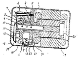
제1도는 본 발명에 의한 급유장치가 적용되는 압축기의 단면도.1 is a cross-sectional view of a compressor to which the oil supply apparatus according to the present invention is applied.
제2도는 그 급유장치의 부분 단면도.2 is a partial cross-sectional view of the oil supply device.
제3도는 본 발명에 있어서의 압축기의 단면도.3 is a cross-sectional view of the compressor in the present invention.
제4도는 그 급유장치의 부분 단면도.4 is a partial cross-sectional view of the oil supply device.
제5도 내지 제8도는 본 발명에 의한 급유장치의 별도의 실시예를 도시한 부분 단면도.5 to 8 are partial cross-sectional views showing another embodiment of the oil supply apparatus according to the present invention.
* 도면의 주요부분에 대한 부호의 설명* Explanation of symbols for main parts of the drawings
1 : 케이스 2 : 실린더1: case 2: cylinder
5 : 측판(側板) 6 : 측판5: side plate (側板) 6: side plate
8 : 실린더 홈(溝) 9 : 용수철8
10 : 베인(vane) 11 : 베인 뒷면10: vane 11: the back of the vane
12 : 펌프 실 13 : 기름12: pump chamber 13: oil
14 : 흡인포트(吸![]()
![]()
16 : 토출 포트 36 : 소경부 구멍 단면16
37 : 스페이스 38 : 소경부 구멍 단면37: space 38: small diameter hole cross section
50 : 스페이스 51 : 급유로50: space 51: oil supply passage
52 : 하향(下向)흡인포트 53 : 취부 구멍(取付穴)52: downward suction port 53: mounting hole
54 : 흡인 피이스(piece)54: suction piece
본 발명은, 예를들면 냉장고 공기 조화기(空氣調和機) 등의 냉동 장치에 조립되는 가로형의 압축기에 관하여, 특히 그 윤활(潤滑) 급유장치에 관한 것이다.TECHNICAL FIELD This invention relates especially to the lubricating oil supply apparatus regarding the horizontal compressor assembled | attached, for example in refrigeration apparatuses, such as a refrigerator air conditioner.
본 특허 출원인이 1984년 2월 7일 특허 제562호로 출원한 가로형 로터리 압축기의 급유장치를 제1도에 도시한다. 케이스 1내에 케이스 1에 고정된 실린더(cylinder) 2,크랭크(crank) 3을 가진 샤프트(shaft) 4,샤프트의 축수(軸受)와 실린더의 측벽(側壁)을 겸하고, 실린더 2에 부설되어 있는 측판 5, 측판 6, 크랭크 3에 개재(介在)된 로울러(roller) 7, 실린더 홈 8을 스라이드(slide)하고, 크랭크 3의 회전에 따라서 회전하는 로울러 7에 선단(先端)이 접하고, 다른쪽이 용수철 9에 눌러서 실린더 홈 내를 왕복 운동하는 베인 10에 의해 압축 요소가 구성되며, 베인 10의 뒷면 11과 실린더 홈 8과 측판 5과 측판 6과 케이싱(casing) 1에 의해 둘러 싸여지는 펌프 실 12가 형성되고, 측판 5에는 케이스 1내의 기름 13을 펌프실 12내에 흡인할 수 있는 흡인 포트 14가 있고, 측판 6에는 펌프실 12에서 기름을 송유로 15에 토출할 수 있는 토출포트 16이 있으며, 송유로 15는 샤프트 4의 측 구멍 17에 기름을 공급할 수 있도록 구성되고, 더욱이 측 구멍에서 분기 구멍 13을 통해서 소요의 윤활부에 급유할 수 있도록 되어 있다.FIG. 1 shows a lubrication device for a horizontal rotary compressor filed in Patent No. 562 of February 7, 1984, by the present applicant. Cylinder 2 fixed to case 1 in case 1, shaft 4 with
그리고, 샤프트 4의 다른 쪽에는 스테이터(stator) 19에 의해 회전력을 주어 샤프트 4를 회전시키는 로오터(rotor)가 부설되어 있다.On the other side of the shaft 4, a rotor is provided to rotate the shaft 4 by applying a rotational force by the
상기, 급유기구의 펌프 부분을 제2도에 의해서 설명한다. 흡인포트 14는 펌프실 12측에 개구(開口)하는 부분의 지름이 적고, 그 반대측의 케이스 1내의 기름 13을 개구하는 부분의 지름이 큰 테이퍼(taper) 상태의 구멍으로 되어 있다. 한편 토출(吐出) 포트(port) 16은 펌프실 12측에 개구하는 부분의 지름이 크며, 그 반대측의 송류로 15에 개구하는 부분의 지름이 적은 테이퍼 상태의 구멍으로 되어 있고, 상기 소경부(小經部)와 송유로 15의 사이에 스페이스(space) 37을 마련하고 있다. 따라서, 흡인 포트 14, 토출 포트 16등이 지름이 큰 쪽에서 지름이 작은 쪽으로의 순방향으로 기름이 흐를 때에는 흐르기 쉬우나 역으로 펌프 실 12에서 소경부 구멍 단면 36을 통해 지름이 큰 쪽으로 역류할려고 할 때에는, 소경부 구멍 단면 36의 에지(edge) 효과에 의해 유동저항(流動抵抗)이 커져서 역류하기 어렵다. 마찬가지로, 스페이스 37에서 소경부 구멍 단면 38을 통해 지름이 큰 쪽으로 역류할 때에도 저항이 크다.The pump portion of the oil supply mechanism will be described with reference to FIG. The suction port 14 is a tapered hole having a small diameter of a portion that opens on the
이상의 구성에 있어서, 압축기를 운전하고, 샤프트 4가 회전하면, 이에 따라서 로울러 7이 회전하여 베인 10은 용추철 9에 의해 눌러저, 로울러 7에 선단이 접하면서 실린더 홈 8내를 왕복 운동 한다. 베인 10이 왕복운동 하면 펌프실 12의 용적이 변화하고, 펌프 작용을 운행한다. 즉, 펌프실 12의 용적이 커지면, 흡입포트 14에서 기름을 흡입하고, 펌프실 12의 용적이 적어지면 토출포트 11에서 기름을 송류로 15에 토출된다. 송유로 15에 보내진 기름은 측 구멍 17분기(分岐)구멍 18을 통해서 소요의 윤활 부분에 급유된다.In the above configuration, when the compressor is driven and the shaft 4 rotates, the
그러나, 상기한 급유 장치에는 다음에 제시하는 문제가 원다. 케이스 1내의 유량에 변동을 일으켜서 유면(油面)이 저하하든지 압축기 자체가 경사 시켜서 설치되면, 흡입포트 14의 흡입구의 일부가 유면보다 위로 나오는 수가 있다.However, the above-mentioned oil supply apparatus suffers from the following problems. If the oil level decreases due to fluctuations in the flow rate in the case 1, or if the compressor itself is inclined, a part of the suction port of the suction port 14 may come out above the oil level.
이와같은 때에, 흡입포토 14에서 펌프실 12에 케이스 1내의 까스가 혼입(混入)하여, 펌프작용이 방해되어 기름이 샤프트 4의 급유구인 측 구멍 17에 충으히 공급되지 않게 된다.In such a case, the gas in the case 1 enters into the
본 발명의 목적은 상술한 급유장치를 개량하고, 케이스내의 유면저하(油面低下)시에도 충분한 급유량을 확보할 수 있는 장치를 제공 하는데 있다.An object of the present invention is to improve the above-mentioned oil supply device and to provide a device capable of ensuring a sufficient oil supply amount even when the oil level in the case is lowered.
상기 목적을 달성하기 위해서, 케이스 내의 기름을 펌프실로 인도하는 흡입포트의 흡입구를 하향으로 개구시키는 것에 의해 유면이 저하 할때에도 안정된 급유량이 확보될 수 있는 구조로 한다.In order to achieve the above object, a stable oil supply can be ensured even when the oil level is lowered by opening the suction port of the suction port leading the oil in the case to the pump chamber downward.
본 발명의 실시예를 제3도에 의해서 설명한다.An embodiment of the present invention will be described with reference to FIG.
제3도에 있어서의 압축요소, 압축 기구요소, 및 급유기구의 구성은 제1도와 마찬가지이다.The structure of the compression element, the compression mechanism element, and the oil supply mechanism in FIG. 3 is the same as that of FIG.
본 발명에 있어서의 급유 기구의 흡입포트 14의 구성은 제4도에 의해서 상세하게 설명한다. 50은 측판에 마련되어 펌프실 12에 통하는 스페이스, 51은 측판 5의 하단에 마련된 급유로, 52는 상기 스페이스 50에 통하고 급유로 51에 수직 하향으로 개구하는 하향흡입 포트이다.The structure of the suction port 14 of the oil supply mechanism in this invention is demonstrated in detail by FIG. 50 is a space provided in the side plate and communicates with the
이상의 구성에 있어서, 압축기를 운전하여 샤프트 4가 회전하면 이에 따라서 로울러 7이 회전하며, 베인 10은 용수철 9에 의해 눌러저, 로울러 7에 선단이 접하면서 실린더 홈 8내를 종래의 압축기와 마찬가지로 상하로 왕복운동한다. 베인 10의 왕복운동에 의해 펌프실 12의 용적이 변화하고, 펌프 작용을 행한다. 즉, 펌프실 12의 용적이 커질때, 케이스 1내의 기름 13을 급유로 51을 통해서 하향흡입포트 52에서 스페이스 50 및 펌프실 12로 흡입한다. 이때, 송유로 15에서의 기름의 역류는 토출포트 16의 역류저항이 크기 때문에 적다. 펌프실 12의 용적이 적어질때, 토출포트 16에서 기름을 송유로 15에 토출하고, 하향흡입포트 52에 있어서의 역류 저항이 크기 때문에 케이스 1으로의 역류는 적다.In the above configuration, when the shaft 4 is rotated by driving the compressor, the
이상과 같이, 급유펌프작용을 행하는 가로형 압축기의 급유장치에 있어서, 케이스 내의 기름 13을 측판 5의 최하단에 마련한 급유로 51에서 흡인한다. 즉, 종래에 비해서 케이스 1의 바닦(府)가까운 곳에서 흡입할 수가 있기 때문에, 케이스 1의 기름 13의 량이 변동하여 유면이 저하 할 때에도 흡입구로되는 급유로 51이 유면보다 위로 나올 위험이 적다.As described above, in the lubrication device of the horizontal compressor that performs the lubrication pump action, the
또, 하향 흡입 포트 52출구에 마련한 스페이스 50에는 더욱이 다음의 효과가 있다. 하향흡입포트 52의 출구에 스페이스가 있기 때문에 제2도에 도시한 흡입포트 출구인 소경부 구멍단면 36부근을 운동하는 베인 10이 기름이 펌프실 12으로의 유입을 할때의 저항으로 되는 영향이 적고, 또, 출구부에 있어서의 유로 단면적 비가 크게 취할 수가 있으므로, 역류저항도 크게 할 수가 있어 전체로서 하향흡입포트 52의 역지변으로서의 효과를 크게할 수가 있다.In addition, the
다음에 별도의 실시예를 제5도에 의해서 설명한다. 제4도와 동일의 번호를 붙친것은 동일의 부분을 표시하고 같은 효과를 나타낸다. 54는 측판 5와는 별도의 부품으로 제작한 흡입피이스(piece) 53은 이것을 측판 5에 수직 하향으로 부착하기 위한 부착구멍이다. 흡입 피이스 54를 부착구멍 53에 의해서 측판 5에 부착하는 것에 의해, 상술한 실시예와 마찬가지의 작용을 행한다. 케이스 1내의 기름의 흡입, 측판 5와는 별도의 부품인 흡입피이스 54에서 행하기 때문에, 예를들면, 측판 5가 주철(鑄鐵)과 같이, 약한 재료이라도 절삭하기 쉬운 재료로 되고, 프레스 성형에 의해서 제작한 흡입피이스 54를 사용하면, 흡입피이스 54의 에지부분을 날카롭게 형성할 수가 있고, 또한 균일하게 제작할 수 있다. 따라서, 흡입피이스 54에 있어서의 역류 저항을 크게할 수가 있고, 동시에 균일한 성능을 얻을수 있는 효과가 있다.Next, another embodiment will be described with reference to FIG. Numbering the same as in FIG. 4 marks the same part and gives the same effect. 54 is a
다음에, 별도의 실시예를 제6도에 의해서 설명한다. 제5도가 동일의 번호를 붙인것은 동일의 부품을 표시하고 또, 마찬가지의 효과를 나타낸다. 본 실시예에 있어서 흡입 피이스 54의 출구 부분을 스페이스 50의 내부로 돌기시키고 있다. 이로인해, 흡입피이스 54에 있어서의 역류 저향이 커져서 역지변으로 효과를 크게 할 수가 있다.Next, another embodiment will be described with reference to FIG. Numbering the same numbers in FIG. 5 denotes the same parts and has the same effect. In this embodiment, the outlet portion of the
다음에, 별도의 실시예를 제7도에의 해서 설명한다. 제5도와 동일의 번호를 붙인 것은 동일의 부품을 표시하고, 마찬가지의 효과를 나타낸다. 본 실시예에 있어서 흡입 피이스 설치 구멍 53을 스트레이트(straight)한 구멍으로 하고, 흡입 피이스 54의 흡입구에 원통상 압입(壓入) 영역을 마련하여 부착구멍에 압입하여 고정하고 있다. 따라서, 부착구멍 53의 가공이 용이하게 됨과 동시에 흡입 피이스 54의 고정이 확실한 것이 되여, 부착 위치로 균일하게할 수가 있어, 균일한 급유 성능이 얻어지는 효과가 있다.Next, another embodiment will be described with reference to FIG. The same numbers as in FIG. 5 denote the same parts, and have the same effects. In this embodiment, the suction
다음에, 별도의 실시예를 제8도에 의해서 설명한다. 제7도와 동일의 번호를 붙인것은 동일의 부품을 표시하고 마찬가지의 효과를 나타낸다. 본 실시예와 마찬가지로 부착 구멍 53을 스트레이트 구멍으로 하고, 흡입 피이스 54의 흡입구에 원통상의 압입 영역을 마련하고, 더욱이 흡입 피이스 54의 출구 부불을 스페이스 50의 내부에 돌기시킨 것이다. 흡입 피이스 54의 출구를 스페이스 50에 돌기 시킨 것에 의해, 역류 저항이 증가하여, 역지변(逆止弁)으로서의 효과를 크게할 수가 있어 충분한 급유량을 확보할 수 있다.Next, another embodiment will be described with reference to FIG. The same numbers as in FIG. 7 denote the same parts and have the same effect. Similarly to this embodiment, the
본 발명에 의하면, 펌프의 케이스의 바닥 가깝게 마련할 수가 있기 때문에 케이스 내의 유량이 변동하여 유면이 저하할 때에도 흡입구가 유면위에 나오는 위험이 적고, 안정된 급유량을 확보할 수가 있다.According to the present invention, the pump can be provided close to the bottom of the casing, so that even when the flow rate in the casing fluctuates and the oil level decreases, the inlet port is less likely to come on the oil surface, and a stable oil supply can be ensured.
Claims (5)
Applications Claiming Priority (2)
| Application Number | Priority Date | Filing Date | Title |
|---|---|---|---|
| JP58-92286 | 1983-05-27 | ||
| JP58092286A JPS59218389A (en) | 1983-05-27 | 1983-05-27 | Oil supply device in horizontal type rotary compressor |
Publications (2)
| Publication Number | Publication Date |
|---|---|
| KR850000603A KR850000603A (en) | 1985-02-28 |
| KR860000352B1 true KR860000352B1 (en) | 1986-04-12 |
Family
ID=14050161
Family Applications (1)
| Application Number | Title | Priority Date | Filing Date |
|---|---|---|---|
| KR1019840001371A KR860000352B1 (en) | 1983-05-27 | 1984-03-17 | Oil supply device in horizontal type rotary compressor |
Country Status (5)
| Country | Link |
|---|---|
| US (1) | US4544338A (en) |
| JP (1) | JPS59218389A (en) |
| KR (1) | KR860000352B1 (en) |
| DK (1) | DK156181C (en) |
| ES (1) | ES532756A0 (en) |
Families Citing this family (13)
| Publication number | Priority date | Publication date | Assignee | Title |
|---|---|---|---|---|
| JPS61241492A (en) * | 1985-04-17 | 1986-10-27 | Hitachi Ltd | Oil feeding device for horizontal type rotary compressor |
| US4917582A (en) * | 1989-02-27 | 1990-04-17 | Carrier Corporation | Horizontal scroll compressor with oil pump |
| US4946361A (en) * | 1989-03-06 | 1990-08-07 | Carrier Corporation | Horizontal scroll compressor with oil pump |
| IT1243006B (en) * | 1989-09-08 | 1994-05-23 | Mitsubishi Electric Corp | HORIZONTAL ROTATING COMPRESSOR |
| US5322420A (en) * | 1992-12-07 | 1994-06-21 | Carrier Corporation | Horizontal rotary compressor |
| US5470214A (en) * | 1992-12-17 | 1995-11-28 | Goldstar Co., Ltd. | Lubricating device for horizontal type hermetic compressor |
| CN1100207C (en) * | 1996-08-05 | 2003-01-29 | Lg电子株式会社 | Lubricant structure of closed-type transmission compressor |
| JP3718027B2 (en) * | 1997-03-31 | 2005-11-16 | 東芝キヤリア株式会社 | Rotary compressor |
| CA2809945C (en) | 2010-08-30 | 2018-10-16 | Oscomp Systems Inc. | Compressor with liquid injection cooling |
| US9267504B2 (en) | 2010-08-30 | 2016-02-23 | Hicor Technologies, Inc. | Compressor with liquid injection cooling |
| JP2012177353A (en) * | 2011-02-28 | 2012-09-13 | Sanyo Electric Co Ltd | Multistage compression type rotary compressor and compression type rotary compressor |
| CN103982438B (en) * | 2014-05-22 | 2016-02-17 | 广东美芝制冷设备有限公司 | Horizontal rotary compressor |
| JPWO2021005688A1 (en) * | 2019-07-08 | 2021-01-14 |
Family Cites Families (12)
| Publication number | Priority date | Publication date | Assignee | Title |
|---|---|---|---|---|
| US252946A (en) * | 1882-01-31 | Thomas m | ||
| GB303953A (en) * | 1928-07-28 | 1929-01-17 | Graham Enoch Mfg Company Ltd | Improvements in air or gas compressors |
| DE511046C (en) * | 1929-06-14 | 1930-10-25 | Aeg | Circulating lubrication for capsule compressors, in which the guide tongue of the compressor piston serves as a displacement piston for the circulating lubrication |
| US2709891A (en) * | 1945-06-13 | 1955-06-07 | James Y Dunbar | Valveless resonating jet motor |
| US2883101A (en) * | 1956-04-16 | 1959-04-21 | Gen Electric | Rotary compressor |
| US3135460A (en) * | 1960-10-19 | 1964-06-02 | Gen Motors Corp | Refrigerating apparatus |
| US3565552A (en) * | 1968-03-19 | 1971-02-23 | Tokyo Shibaura Electric Co | Rotary compressor |
| US3897173A (en) * | 1973-03-22 | 1975-07-29 | Harold Mandroian | Electrolysis pump |
| JPS5620795A (en) * | 1979-07-28 | 1981-02-26 | Toshiba Corp | Rotary compressor |
| JPS5620796A (en) * | 1979-07-28 | 1981-02-26 | Toshiba Corp | Rotary compressor |
| US4385875A (en) * | 1979-07-28 | 1983-05-31 | Tokyo Shibaura Denki Kabushiki Kaisha | Rotary compressor with fluid diode check value for lubricating pump |
| JPS59165888A (en) * | 1983-03-10 | 1984-09-19 | Hitachi Ltd | Horizontal compressor |
-
1983
- 1983-05-27 JP JP58092286A patent/JPS59218389A/en active Granted
-
1984
- 1984-03-17 KR KR1019840001371A patent/KR860000352B1/en not_active IP Right Cessation
- 1984-05-15 US US06/610,440 patent/US4544338A/en not_active Expired - Lifetime
- 1984-05-24 ES ES532756A patent/ES532756A0/en active Granted
- 1984-05-25 DK DK257784A patent/DK156181C/en active
Also Published As
| Publication number | Publication date |
|---|---|
| DK156181C (en) | 1989-11-20 |
| JPS59218389A (en) | 1984-12-08 |
| US4544338A (en) | 1985-10-01 |
| DK257784D0 (en) | 1984-05-25 |
| KR850000603A (en) | 1985-02-28 |
| ES8505039A1 (en) | 1985-04-16 |
| ES532756A0 (en) | 1985-04-16 |
| JPH0151915B2 (en) | 1989-11-07 |
| DK156181B (en) | 1989-07-03 |
| DK257784A (en) | 1984-11-28 |
Similar Documents
| Publication | Publication Date | Title |
|---|---|---|
| KR860000352B1 (en) | Oil supply device in horizontal type rotary compressor | |
| KR860000977B1 (en) | Rotary compressor | |
| KR20070061966A (en) | Oil feeding structure for scroll compressor | |
| US4543047A (en) | Rotary compressor | |
| KR100321687B1 (en) | Fluid pump | |
| US3521981A (en) | Pump or compressor | |
| JPH0711278B2 (en) | Horizontal rotary compressor | |
| JPS61106992A (en) | Rotary compressor | |
| WO1991006767A1 (en) | Scroll compressor | |
| JPS59226294A (en) | Oil supplying device for compressor | |
| JP2004225578A (en) | Rotary compressor | |
| KR960001190Y1 (en) | Rotary compressor | |
| EP0444221A1 (en) | Vertical rotary compressor | |
| KR940001215B1 (en) | Horizontal compressor | |
| KR850000702Y1 (en) | Horizontal rotar compressor | |
| JPS5960091A (en) | Horizontal type scroll compressor | |
| KR100703665B1 (en) | Crank-shaft for compressor | |
| KR940005886A (en) | Inclined Plate Compressor | |
| JP2539892B2 (en) | Horizontal compressor | |
| KR200158617Y1 (en) | Reciprocating type compressor | |
| KR200150834Y1 (en) | Rotary compressor | |
| KR840001200B1 (en) | Rotary compressor | |
| JPH0196486A (en) | Enclosed scroll compressor | |
| JPS6245096Y2 (en) | ||
| KR890001738B1 (en) | Rotary type compressor |
Legal Events
| Date | Code | Title | Description |
|---|---|---|---|
| A201 | Request for examination | ||
| G160 | Decision to publish patent application | ||
| E701 | Decision to grant or registration of patent right | ||
| GRNT | Written decision to grant | ||
| FPAY | Annual fee payment |
Payment date: 20030226 Year of fee payment: 18 |
|
| EXPY | Expiration of term |