KR850001803B1 - High frequency heating device - Google Patents
High frequency heating device Download PDFInfo
- Publication number
- KR850001803B1 KR850001803B1 KR1019810004120A KR810004120A KR850001803B1 KR 850001803 B1 KR850001803 B1 KR 850001803B1 KR 1019810004120 A KR1019810004120 A KR 1019810004120A KR 810004120 A KR810004120 A KR 810004120A KR 850001803 B1 KR850001803 B1 KR 850001803B1
- Authority
- KR
- South Korea
- Prior art keywords
- high frequency
- heating chamber
- stub
- opening
- heating
- Prior art date
Links
Images


Classifications
-
- H—ELECTRICITY
- H05—ELECTRIC TECHNIQUES NOT OTHERWISE PROVIDED FOR
- H05B—ELECTRIC HEATING; ELECTRIC LIGHT SOURCES NOT OTHERWISE PROVIDED FOR; CIRCUIT ARRANGEMENTS FOR ELECTRIC LIGHT SOURCES, IN GENERAL
- H05B6/00—Heating by electric, magnetic or electromagnetic fields
- H05B6/64—Heating using microwaves
Abstract
Description
제1도는 종래예의 전체 개략구성을 도시한 측단면도.1 is a side cross-sectional view showing an overall schematic configuration of a conventional example.
제2도는 본 발명을 따른 한 실시예의 전체적인 개략구성을 도시한 평면도.2 is a plan view showing an overall schematic configuration of an embodiment according to the present invention.
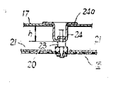
제3도는 동 축단면도.3 is a coaxial section view.
제4도는 회전원판을 도시한 평면도.4 is a plan view showing a rotating disc.
제5도는 요부구성을 도시한 축단면도.5 is an axial sectional view showing a main part configuration.
제6도는 제1의 실험에 있어서 용기의 배치상태를 도시한 평면도.6 is a plan view showing the arrangement of containers in the first experiment.
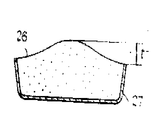
제7도는 제2의 실험에 있어서 스폰지 케이크의 구어진 상태를 도시한 측단면도.FIG. 7 is a side cross-sectional view showing a wrinkled state of a sponge cake in a second experiment. FIG.
* 도면의 주요부분에 대한 부호의 설명* Explanation of symbols for main parts of the drawings
11 : 본체 12 : 원형구멍(개구부)11
13 : 가열실 14 : 마그네트론(고주파발진기)13
15 : 회전원판 16 : 간막이판15: rotating disc 16: partition plate
19 : 도파관 20 : 기판19: waveguide 20: substrate
21 : 금속편 22 : 여진구21: metal piece 22: aftershock
24 : 스터브(stub)24: stub
본 발명은 고주파 발전기에 의하여 발신된 고주파를 가열실내에 도입하다 도파관을 구비한 고주파 가열장치에 관한 것이다.BACKGROUND OF THE INVENTION 1. Field of the Invention The present invention relates to a high frequency heating device including a waveguide for introducing a high frequency transmitted by a high frequency generator into a heating chamber.
이러한 종류의 고주파 가열장치, 예를 들면 전자레인지는 제 1 도에 도시한 것과 같이 본체(1) 내에 가열실(2)과 마그네트론(고주파 발진기) (3)이 수납되고 마그네트론(3)에서 발신된 고주파를 도파관(4)을 통해서 가열실(2)의 천정면에 설치된 여진구(5)로부터 가열실(2)내로 도입하는 동시에 가열실(2)의 상부에 설치된 교반팬(stirrer fan)(6)에 의하여 고주파를 난확산(亂擴散)시켜서 가열실(2)내에 도입되는 고주파 에너지의 분포를 양호한 상태를 조정하도록 구성한 것이었다. 또, (7)은 교반팬(6)을 하방에서 차폐하는0저유전체로 구성되는 간막이판이다.In this kind of high frequency heating apparatus, for example, a microwave oven, as shown in FIG. 1, a
그러나, 상기 구성의 고주파 가열장치에 있어서는 , 가열실(2)내에 교반팬(6)이 설치되어 있으므로 가열실(2)내에는 교반팬(6)을 수납하기 위한 비교적 큰 수납스페이스(8)가 필요한 동시에, 간막이판(7)의 높이치수 ι을 비교적 높게 구성해야 하고, 가열실(2)내의 조리용 스페이스(9)를 일정량으로 유지할 경우 가열실(2) 전체가 비교적 대형이 되어 장치전체를 소형화하는데 문제가 있었다.However, in the high frequency heating apparatus having the above-described configuration, since the stirring fan 6 is provided in the
본 발명은 상기의 사정을 고려하여 연구된 것으로서, 그 목적은 가열실내에 도입되는 고주파 에너지의 분포를 양호한 상태로 조정가능할 뿐만 아니라 간막이판의 높이치수를 비교적 작게 할 수 있고, 장치전체를 소형화시킬 수 있는 고주파 가열장치를 제공하는 데 있다.The present invention has been studied in view of the above circumstances, and its object is not only to adjust the distribution of high frequency energy introduced into the heating chamber in a good state, but also to make the height dimension of the partition board relatively small, and to reduce the size of the whole apparatus. It is to provide a high-frequency heating device that can be.
이하, 본 발명의 한 실시예를 제 2 도내지 제 7 도를 참조해서 설명한다. 제 2 도 및 제 3 도는 고주파 가열장치, 예를 들면 전자전자레인지 전체의 개략구성을 나타내는 것으로서, (11)은 본체이다. 본체(11)에는 상면중앙에 원형구멍(개구부)(12)을 가지는 가열실(13)과 마그네트론(고주파 발진기)(14)이 수납되어 있다. 가열실(13)의 저부에는 식품을 놓는 선반(13a)이 설치되어 있다. 가열실(13)의 원형구멍(12)의 하방은 저유전체로 구성되고, 후기하는 회전원판(15)을 차폐하는 간막이판(16)에 의하여 폐쇄되고, 또한 원형구멍(12)의 상방은 공동상자(17)에의하여 폐쇄되어 있다. 이 공동상자(17)는 마그네트론(14)의 안테나부(14a)를 덮는 연결부(18)과 함께 도파관(19)을 형성한다. 또, 원형구멍(12)에는 이 원형구멍(12)보다 약간 작은 상기 회전원판(15)이 배치된다. 이 회전원판(15)은 제 4 도와 같이 저유전체로 구성되는 원형의 기판(20)과 이 기판(20)상에 배설된 4장의 금속편(21)으로 형성된다. 각 금속편(21)사이는 소정간격으로 이격되고, 각 금속편(21)에 의하여 자상의 여진구(22)가 형성된다.Hereinafter, an embodiment of the present invention will be described with reference to FIGS. 2 to 7. 2 and 3 show a schematic configuration of a high-frequency heating apparatus, for example, an entire microwave oven, where 11 is a main body. The main body 11 houses a
회전원판(15)의 중앙부에는 제 5 도에 도시한 바와같이 회전축(23)이 장착되어 있다. 또, 원형구멍(12)의 대략 중앙부위와 대향시켜서 상기 공동상자(17)에는 스터브(24)가 안쪽으로 돌설된다. 이 스터브(24)의 플랜지부(24a)는 공동상자(17)의 외면에 예를 들면 나사고정이나 용접 등에의해 단단히 고착되고 고주파의 누설이 방지되도록 되어 있다. 스터브(24)의 높이치수 h는 마크네트론(14)에서 발신되는 고주파의 파장λ(λ=12.2cm)의 약 1/4로 설정되어 있다. 또, 회전원판(15)의 회전축(23)은 스터브(24)에 의하여 회전가능하게 축지되어 있다. 그리고, 회전원판(15)을 공동상자(17)의 외부에 설치된 도시하지 않은 모우터에 의하여 회전구동되도록 되어 있다.The
그리하여, 상기 구성에 있어서는 마그네트론(14)에서 발신되는 고주파가 연결부(18)에 의하여 공동상자(17)내로 유도된다. 공동상자(17)내로 유도된 고주파는 각 금속편(21)의 표면에서 대략 전반사되어 여진구(22)를 통해서 가열실(13)내로 도입되고, 여진구(22)는 회전원판(15)의 회전에 따라 회전되므로 가열실(13)내에 도입되는 고주파를 대략 균등하게 분포시킬 수 있다.Thus, in the above configuration, the high frequency transmitted from the
또, 공동상자(17)에 스터브(24)를 설치함으로써 여진구(22)의 중앙부위를 통해서 가열실(13)내로 도입되는 고주파 에너지를 강하게 할 수가 있고, 가열실(13)내에 도입되는 고주파 에너지의 분포를 양호한 상태로 조정할 수가 있다. 출원인은 다음의 제 1, 제 2 의 실험에 의하여 이 사실을 확인했다.Moreover, by providing the
제 1 의 실험은 제 6 도와 같이 가열실(13)의 선반(13a)위에 5개의 용기(25)를 적절히 배치하고, 마그네트론(14)을 일정시간(2분 30초) 동작시켜서 각 용기(25)에 수용되는 물(300cc)의 온도상승치를 조사하여, 온도상승치의 분포상태에서 가열실(13)에 도입되는 고주파 에너지의 분포상태를 조사하도록 한 것이다.In the first experiment, as in the sixth diagram, five
여기에서,From here,
분포울(Y)=
로 한다. 또, 회전원판(15)의 직경은 180mm, 여진구(22)를 형성하는 각 금속편(21)간의 간격은 25mm 스터브(24)의 직경은 30mm이고, 높이 치수 h가 상이한 스터브(24)를 6종류 사용한다. 실험결과를 제1표에 표시한다.Shall be. Moreover, the diameter of the rotating
[제1표][Table 1]

이 표에서 명백히 알수 있듯이, 공동상자(17)에 스터브(24)를 설치하지 아니하는 경우에는 분포율(Y)이 비교적 크기 때문에, 각 용기(25)내의 물의 온도 상승치의 차이가 커진다. 이 경우, 선반(13a)이 중앙부에 위치한 용기(25)내의 물의 온도 상승치가 최소치로 되고 있다. 또, 높이치수 h가 30mm(약λ/4)의 스터브(24)를 공동상자(17)에 설치한 경우, 분포율은 가장 작아져서 각 용기(25)내의 물의 온도상승치의 차가 작아진다. 따라서 공동상자(17)에 스터브(24)를 설치하지 않은 경우는 선반(13a)의 중앙부위의 식품 등은 주위부의 것보다도 가열이 잘되지 아니하나 높이치수 h가 마그네트론(14)에서 발신되는 고주파의 피장외 약 1/4(30mm)이 되는 스터브(24)를 공동상자(17)어 설치함으로써 여진구(22)의 중앙부위를 통해서 가열실(13)내에 도입되는 고주파 에너지를 강화하여 가열실(13)내로 도입되는 고주파 에너지의 분포를 양호한 상태로 조정할 수가 있고, 선반(13a) 위에 놓인 식품 등을 균일하게 가열할 수가 있다.As is apparent from this table, when the
제 2 의 실험은 제 7 도에서와 같이 스폰지케이크(26)의 재료를 수용한 용기(27)를 가열실(13)의 선반(13a)위에 올려놓고 높이치수 h가 다른 6종류의 스터브(24)마다 스폰지케이크(26)의 구어진 상태(스폰지케이크(26)의 중앙부의 부푼치수 t)를 조사한 것이다.In the second experiment, as shown in FIG. 7, six kinds of
실험결과를 제 2 표에 표시한다.The experimental results are shown in the second table.
[제2표][Table 2]

이 표에서도 명백히 알 수 있듯이, 공동상자(17)에 스터브(24)를 설치하지 않는 경우에는 스폰지케이크(26)의 중앙부위가 높이 부풀고(t의 값이 커진다), 높이치수 h가 30mm(약λ/4)의 스터브(24)를 공동상자(17)에 설치했을 경우에는 스폰지케이크(26)의 중앙부위의 부푼양을 적게(t의 값을 적게)할 수가 있다. 따라서 높이치수 h가 30mm의 스터브(24)를 공동상자(17)에 설치함으로써 스폰지케이크(26) 전체를 대략 균일하게 가열할 수가 있으므로 스폰지케이크(26) 등의 비교적 용량이 큰 것이라도 양호한 상태로 구어낼 수 있다.As can be clearly seen from this table, when the
또, 종래의 교반팬(6)을 대신하는 회전원판(15)은 가열실(13) 상면의 원형구멍(12)내에 배치되고 있으므로 종래의 것에 비해서 가열실(13)내에 있어서의 교반팬(6)의 수납스페이스(8)의 부분을 없앨 수 있는 동시에 간막이판(16)의 높이치수 L을 비교적 작게 할 수 있다. 그러므로, 가열실(13)내의 조리용 스페이스를 일정하게 유지할 경우 가열실(13) 전체의 치수를 종래보다도 소형화할 수 있다. 따라서, 장치전체를 소형화할 수 있다.Moreover, since the
또, 본 발명은 상기 실시에에 한정되는 것은 아니다. 예를 들면 스터브(24)는 도파관(19)을 깊게 드로우잉 가공해서 일체성형해도 된다.In addition, this invention is not limited to the said Example. For example, the
이상 설명한 바와 같이, 본 발명은 가열실에설치한 개구부의 대략 중앙부위와 대향되게 도파관내에 스터브를 돌설함으로써 상기 개구부내에 배치된 회전원판의 대략 +자상의 여진구의 중앙부위를 통해서 상기 가열실내에 도입되는 고주파 에너지를 강하게 할 수 있으므로, 상기 가열실내에 도입되는 고주파 에너지의 분포를 양호한 상태로 조정할 수가 있다. 똥, 상기 회전원판은 상기 개구부내에 배치되고 있으므로, 상기회전원판을 차폐하는 간막이판의 높이치수를 비교적 작게할 수가 있고, 그 때문에 일정용량의 조리용 스페이스를 유지한 경우에 가열실 전체의 치수를 소형화할 수 있으므로, 장치전체를 소형화하는 데 유리하다.As described above, the present invention introduces into the heating chamber through the central portion of the approximately + magnetic excitation port of the rotating disc disposed in the opening by projecting the stub in the waveguide opposite the approximately central portion of the opening provided in the heating chamber. Since the high frequency energy used can be strengthened, the distribution of the high frequency energy introduced into the said heating chamber can be adjusted to a favorable state. Since the rotating disc is disposed in the opening, the height dimension of the partition plate which shields the rotating disc can be made relatively small, so that the dimensions of the entire heating chamber can be reduced when a constant volume of cooking space is maintained. Since it can be downsized, it is advantageous to downsize the whole apparatus.
Claims (3)
Applications Claiming Priority (3)
| Application Number | Priority Date | Filing Date | Title |
|---|---|---|---|
| JP161056 | 1980-11-11 | ||
| JP1980161056U JPS618555Y2 (en) | 1980-11-11 | 1980-11-11 | |
| JP55-161056 | 1980-11-11 |
Publications (2)
| Publication Number | Publication Date |
|---|---|
| KR830008627A KR830008627A (en) | 1983-12-10 |
| KR850001803B1 true KR850001803B1 (en) | 1985-12-21 |
Family
ID=29519978
Family Applications (1)
| Application Number | Title | Priority Date | Filing Date |
|---|---|---|---|
| KR1019810004120A KR850001803B1 (en) | 1980-11-11 | 1981-10-28 | High frequency heating device |
Country Status (2)
| Country | Link |
|---|---|
| JP (1) | JPS618555Y2 (en) |
| KR (1) | KR850001803B1 (en) |
-
1980
- 1980-11-11 JP JP1980161056U patent/JPS618555Y2/ja not_active Expired
-
1981
- 1981-10-28 KR KR1019810004120A patent/KR850001803B1/en active
Also Published As
| Publication number | Publication date |
|---|---|
| JPS5783696U (en) | 1982-05-24 |
| JPS618555Y2 (en) | 1986-03-17 |
| KR830008627A (en) | 1983-12-10 |
Similar Documents
| Publication | Publication Date | Title |
|---|---|---|
| RU2236162C1 (en) | Cooking vessel used in microwave oven (versions) | |
| US5180895A (en) | Microwave heating apparatus | |
| US4476362A (en) | High frequency heating apparatus | |
| KR100263209B1 (en) | High frequency heating apparatus | |
| US2888542A (en) | Heating apparatus | |
| US3505490A (en) | Apparatus for thawing of frozen materials | |
| JPH0519276B2 (en) | ||
| JPS6242597B2 (en) | ||
| CA1092660A (en) | Cooking vessel for use in high frequency oven | |
| US4430538A (en) | High-frequency heating device | |
| US2632838A (en) | Ultrahigh-frequency electromag-netic radiation heating method and apparatus | |
| US4508946A (en) | Microwave oven with rotary antenna | |
| JPH0482517A (en) | Cooking vessel for microwave oven | |
| KR850001803B1 (en) | High frequency heating device | |
| US4501945A (en) | Microwave oven provided with turntable | |
| US4430539A (en) | High-frequency heating device | |
| KR20040002168A (en) | Microwave oven, guide roller, cooking tray and dish | |
| GB2122060A (en) | Microwave oven provided with turntable | |
| KR860000375Y1 (en) | High-frequency heating apparatus | |
| CA1163329A (en) | High-frequency heating device with a rotating-disk field stirrer | |
| KR840002418Y1 (en) | High-frequency heating device | |
| JPS6115586Y2 (en) | ||
| JPS6115587Y2 (en) | ||
| JP3750652B2 (en) | High frequency heating device | |
| JP3246095B2 (en) | High frequency heating equipment |