KR850000635B1 - Fiber supplying system in open-end spinning machine - Google Patents
Fiber supplying system in open-end spinning machine Download PDFInfo
- Publication number
- KR850000635B1 KR850000635B1 KR8203250A KR820003250A KR850000635B1 KR 850000635 B1 KR850000635 B1 KR 850000635B1 KR 8203250 A KR8203250 A KR 8203250A KR 820003250 A KR820003250 A KR 820003250A KR 850000635 B1 KR850000635 B1 KR 850000635B1
- Authority
- KR
- South Korea
- Prior art keywords
- rotor
- separator
- outlet
- feed channel
- channel
- Prior art date
Links
Images


Classifications
-
- D—TEXTILES; PAPER
- D01—NATURAL OR MAN-MADE THREADS OR FIBRES; SPINNING
- D01H—SPINNING OR TWISTING
- D01H4/00—Open-end spinning machines or arrangements for imparting twist to independently moving fibres separated from slivers; Piecing arrangements therefor; Covering endless core threads with fibres by open-end spinning techniques
- D01H4/04—Open-end spinning machines or arrangements for imparting twist to independently moving fibres separated from slivers; Piecing arrangements therefor; Covering endless core threads with fibres by open-end spinning techniques imparting twist by contact of fibres with a running surface
- D01H4/08—Rotor spinning, i.e. the running surface being provided by a rotor
Landscapes
- Engineering & Computer Science (AREA)
- Mechanical Engineering (AREA)
- Textile Engineering (AREA)
- Spinning Or Twisting Of Yarns (AREA)
Abstract
Description
제1도는 로우터형 오픈엔드 정방기에 있어서 방사부를 표시하는 단면도.1 is a cross-sectional view showing a radiating part in a rotor type open-end spinning machine.
제2도는 섬유수송채널의 일부를 스피닝보디와 별체로 형성한 로우터형 오픈엔드정방기의 단면도.2 is a cross-sectional view of a rotor type open end spinning machine in which a part of the fiber transport channel is formed separately from the spinning body.
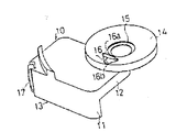
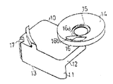
제3도, 제4도는 종래의 섬유수송 채널형성부재의 사시도.3 and 4 are perspective views of a conventional fiber transport channel forming member.
제5도는 동 평면도.5 is a plan view of the same.
제6도는 제5도 A-A선 단면도.6 is a sectional view taken along the line A-A of FIG.
제7도, 제8도는 종래종치의 가시화법(可視化法)에 의한 실험결과를 표시하는 평면도.FIG. 7 and FIG. 8 are plan views showing the results of experiments by the conventional method of visualization.
제9도는 동 세퍼래이터의 배면도.9 is a rear view of the separator.
제10도는 채널속의 공기의 흐름 모형을 표시하는 평면도.10 is a plan view showing a model of the flow of air in the channel.
제11도는 세퍼래이터와 섬유수용채널 형성부재와의 관계를 표시하는 평면도.11 is a plan view showing the relationship between the separator and the fiber receiving channel forming member.
제12도는 제11도의 B-B선 단면도.12 is a cross-sectional view taken along line B-B in FIG.
제13도, 제14도는 본 발명을 구체화시킨 섬유수송채널 형성부재의 사시도.13 and 14 are perspective views of a fiber transport channel forming member incorporating the present invention.
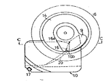
제15도는 동 세퍼래이터와의 관계를 나타내는 평면도.Fig. 15 is a plan view showing a relationship with the separator.
제16도는 제15도 C-C선 단면도.FIG. 16 is a sectional view taken along the line C-C of FIG.
제17도는 본 발명장치의 가시화법에 의한 실험결과를 표시하는 평면도.17 is a plan view showing the results of experiments by the visualization method of the apparatus of the present invention.
제18도는 동 세퍼래이터의 배면도이다.18 is a rear view of the separator.
* 도면의 주요부분에 대한 부호의 설명* Explanation of symbols for main parts of the drawings
2 : 스피닝보디 5 : 코밍로울러2: spinning body 5: coaming roller
6 : 로우터 7 : 섬유수송채널6: rotor 7: fiber transport channel
9 : 세퍼래이터 14 : 세퍼래이터보지부9: Separator 14: Separator support unit
16 : 출구부 16a : 로우터중심축 후단부16:
16b : 로우터외 주측 후단부 θ : 세퍼래이터 확대각16b: Rear end of main part other than rotor θ: Separation angle of separator
α : 채널벽각α: channel wall angle
본 발명은 오픈엔드 정방기에 있어서 섬유수송채널의 구조에 관한 것이다.The present invention relates to a structure of a fiber transport channel in an open end spinning machine.
일반적으로 로우터형 오픈엔드 정방기에 있어서는 제1도에 표시한 바와 같이 슬리이버 1이 스피닝바디 2속에 설치된 공급로울러 3 및 프렛서 4와의 사이에서 규제되면서 공급로울러 3의 회전에 의하여 스피닝 바디 2 속에 설치된 코밍로울러 5로 인도된다.In general, in the rotor type open-end spinning machine, as shown in FIG. 1, the
코밍로울러 5로 인도된 슬라이버 1은 코밍로울러 5에 의하여 분섬되고 고속회전하는 로울터 6의 내부로 연통되도록 스피닝바디 2에 형성된 섬유수송채널 7을 지나서 유입공기과 함께 로우터 6 속으로 수송된다. 로울터 6 속으로 수송된 섬유는 로우터 6의 최대내경부의 수집면 8에 수집되고 가연된후 세퍼래이터 9의 중심에 설치된 안내공 9a로부터 인출되어 보빈(도시하지 않음)에 감겨지도록 되어 있다. 종래 이 종류의 오픈엔드 정방기에서는 세퍼래이터 9에 대한 섬유의 부착이나 슬러브의 발생이 이르났으나 그 원인은 명백하지 않았다.
본 발명자들은 전기한 섬유수송 채널 7중의 코밍로울러 5 이후의 부분을 제2도에 표시한 바와 같이 스피닝바디 2와 별체의 섬유수송채널 형성부재 10이 되게하고, 로우터 6속 특히 세퍼래이터 9 근방의 공기류(流)의 상태를 조사하였다.The present inventors made the portion after the coaming roller 5 of the aforementioned fiber transport channel 7 to be the fiber transport
섬유수송찬널형성부재 10은 제3도,제4도에 표시한 바와 같이 코밍로울러 5의 측면의 일부를 덮는 측벽 11과 코밍로울러 5의 주면의 일부를 덮는 상벽 12로 구성된 본체부 13에 원판상의 세퍼래이터보지부 14가 일체상태로 고착되어 있다. 세퍼래이터보지부 14의 중앙에는 세퍼래이터 9가 감삽되는 감삽공 15가 형성됨과 동시에 그 상면은 제6도에 표시한 바와 같이 중앙이 낮아진 경사상으로 형성되어 있다. 그리고 전기한 세퍼래이터보지부 14에는 전기한 상벽 12에 형성된 섬유수송채널 7의 출구부 16이 형성되어 있다.As shown in FIGS. 3 and 4, the fiber transport
전기한 섬유수송 채널형성부재 10은 측벽 11의 일단에 설치된 스프링 17에 의하여 전기한 스피닝바디 2에 착탈 가능하게 착설될 수 있도록 되어 있다. 공기의 흐르는 상태를 알기 위한 방법으로서 산화티탄을 오일로 녹힌 도료를 채널 7의 내벽, 세퍼래이터 9의 하면 또는 세퍼래이터 보지부 14의 상면에 도포한 상태에서 오픈엔드 정방기에 슬라이버 1을 공급시키지 않고 공운전을 행하여 도료의 부착 또는 박리상태로부터의 공기의 상태를 판단하는 방법(可視化法)을 채용하였다.The aforementioned fiber transport
실험은 어느것이나 로터터 6의 회전수가 60,000 r. p. m, 코밍로울러 5의 회전수가 8,000 r. p. m의 조건으로 행하였다.In all experiments,
제7도에 섬유수송채널 7에만 전기한 도료를 도포하여 실험을 행하였을때의 세퍼래이터 보지부 14 상면에 대한 도료의 부착부분을 검은칠로 표시하였다. 또 제8도, 제9도에는 세퍼래이터보지부 14의 상면 및 세퍼래이터 9의 이면에 전기한 도료를 도포하여 실험을 행하였들때의 도료의 박리부분을 검은칠로 표시하였다. 제8도에 표시한 바와 같이 세퍼래이터보지부 14의 상면주연부의 도료가 박리한 것은 로우터 6의 회전의 수반기류에 의한다.In FIG. 7, the coating portion on the upper surface of the
체널출구부 16의 로우터중심측후단부 16a로부터 로우터 6의 회전방향과 역방향으로 연장되도록 도료의 박리부 X가 생긴 것은 섬유 수송채널 7로부터의 공기가 채널출구부 16의 전방뿐만 아니라 후방에도 강하게 취출(吹出)되고 있음을 표시하고 있다.The peeling part X of the paint was formed from the rotor center side
이러한 사실은 섬유수송채널 7의 내벽에만 도료를 도표했을때의 실험결과에서도 제7도에 표시한 바와같이 채널출구부 16의 로우터중심측후단부 16a로부터 로우터 6의 회전방향과 역방향으로도 도료가 부착한것에 의하여서도 뒷받침되고 있다. 그리고 도료가 타원상으로 부착되고 있다는 것에 의하여 로우터중심측 후단부 16a로부터 채널출구부 16의 후방으로 취출된 공기가 로우터 6의 회전의 수반기류의 영향을 받아서 채널출구부 16의 후방에는 화류(渦流)가 되어있다는 사실이 추정될 수 있다. 채널출구부 16으로부터 후방으로 공기가 취출되는 현상이 생기는 것은 다음과 같은 이유에 의하는 것으로 생각된다.This fact indicates that the paint is attached in the direction opposite to the rotation direction of the
섬유수송채널 7속의 공기의 흐름은 제10도에 표시한 바와 같이 직선의 화살표 R로 표시되는 채널을 따라서 흐름과 화살표 S로 표시되는 순환류로 구성되어 있으며 로우터 6이 제10도의 반시계방향으로 회전할 경우 순환류는 채널출구부 16을 향하여 좌회전방향이 되며 로우터중심축에서는 유속이 빠르고 압력이 낮은 흐름이 된다.The flow of air in the fiber transport channel 7 consists of the flow along the channel indicated by the straight arrow R as shown in FIG. 10 and the circulating flow indicated by the arrow S. The
그리하여 종래의 섬유수송채널 7의 출구부 16은 로우터 중심측후단부 16a가 로우터외주측후단부 16b와 로울러 6의 중심을 맺는 선보다도 후방 즉 공기의 흐름과 반대방향으로 나오게 되도록(張出) 개구되어 있기때문에 그 나오는(張出) 부분으로부터 전기한 순환류가 출구부 16의 후방으로 취출하게 된다. 또 세퍼래이터 9의 이면에 도료를 도포하여 행한 실험에서 제9도에 표시한 바와 같이 도포한 도료의 많은 부분이 박리되어 있다는 것으로부터 섬유수송채널 7로부터의 공기류가 로우터 6 속으로 유입될때 세퍼래이터 9의 이면에 강하게 부닥치게 된다는 사실을 알았다.Thus, the
이와같이 섬유수송채널 7로부터의 공기류가 세퍼래이터 9의 이면에 강하게 부닥치는 것은 세퍼래이터 9의 축에 직교하는 평면과 세퍼래이터 9의 이면을 구성하는 원추모션(母線)이 이루는 각도 즉 세퍼래이터 확대각 θ가 18도 전후인데 종래의 섬유수송채널 7이 제12도에 표시된 바와 같이 로우터속으로 전기한 세퍼래이터 확대각 θ 보다 큰 각도를 이루도록 개구되어 있기 때문인 것으로 생각된다.The strong flow of air from the fiber transport channel 7 on the back side of the
본 발명은 전기한 종래의 결함을 해소시키기 위하여 이루어진 것으로서 그 목적은 섬유수송채널의 출구 부후방으로의 공기의 취출 및 채널로부터의 공기류의 세퍼래이터 이면에의 충돌을 없앰으로써 세퍼래이터의 섬유 부착 및 슬러브의 발생을 방지할 수 있는 오픈엔드 정방기에 있어서의 섬유수송채널의 구조를 제공하는데 있다. 이하 본 발명을 구체화시킨 한가지 실시예를 제13-18도에 따라서 설명한다.SUMMARY OF THE INVENTION The present invention has been made in order to solve the above-mentioned conventional defects, and its object is to remove the air to the rear of the outlet of the fiber transport channel and eliminate the collision of air flow from the channel to the back of the separator. An object of the present invention is to provide a structure of a fiber transport channel in an open end spinning machine capable of preventing fiber adhesion and slugs. Hereinafter, one embodiment incorporating the present invention will be described with reference to FIGS. 13-18.
본 발명에서는 먼저 제15도에 표시한 바와 같이 섬유수송채널 7의 출구부 16의 로우터 중심측후단부 16a를 로우터의 주측후단부 16b와 로우터 6의 중심을 연결하는 선보다도 전방 즉 공기의 흐름의 방향으로 나오도록(張出) 형성하고, 다음에 제16도에 표시한 바와 같이 섬유수송채널 7의 코밍로울러 5의 주면에 대응하는 면(채널벽) 21이 로우터 6의 축에 직교하는 면과 이루는 각 α(이후 채널벽각이라 함)과 세퍼래이터 9 이면과 세퍼래이터 보지부 14 최외단 상면이 이루는 각 즉 세퍼래이터 확대각 θ가 거의 같은 값이 되도록 형성하였다.In the present invention, as shown in FIG. 15, the direction of air flow, that is, the front of the rotor center side
전기한 구조의 섬유수송채널 7에서는 채널출구부 16의 로우터 중심측후단부 16a가 공기의 흐름의 방향에나오도록(張出) 형성되어 있으므로 종래와는 달리 채널속의 공기의 흐름의 일부를 구성하는 순환류가 채널출구부 16의 로우터 중심측 후단부 16a로부터 출구부 16의 후방으로 취출되는 것을 방지할 수가 있다. 또 채널벽각 α와 세퍼래이터확대각 θ를 거의 같이 하였으므로 채널출구부 16으로부터 로우터 6 속으로 취출되는 공기류는 세퍼래이터 9의 이면을 따라서 흘러 세퍼래이터 9에 충돌하는 것을 방지할 수가 있다.In the fiber transport channel 7 having the above-described structure, since the rotor center side
이러한 사실은 제17도, 제18도에 표시한 로우터 6의 회전수가 60,000 r. p. m, 코밍로울러 5의 회전수가 8,000 r. p. m의 조건으로 행한 실험결과에 의하여 증명된다.This fact indicates that the number of revolutions of the
제17도에는 세퍼래이터보지부 14의 상면에 도포한 도료의 박리부분을 검게 칠하여 표시하고 있다. 로우터 6의 회전의 수반기류에 의한 세퍼래이터 보지부 14의 상면주연부의 도료의 박리 및 채널출구부 16의 전방으로의 공기의 취출에 의한 도료의 박리상태는 제8도에 표시한 종래장치의 실험결과와 거의 같다. 그러나 출구부 16의 후방부에는 도료의 박리가 없으므로 종래장치와는 달리 채널출구부 16 후방으로의 공기의 취출이 이르나지 않는다는 것이 명백하다. 또 제18도에는 세퍼래이터 9의 이면에 도포한 도료의 박리부분을 검게 칠하여 표시하고 있다. 박리부분이 매우 적다는 것에 의하여 섬유수송채널 7로부터 공기류가 세퍼래이터 9의 이면에 거의 충돌하고 있지 않음을 알 수가 있다.In FIG. 17, the peeling part of the coating material apply | coated on the upper surface of the
또한 제15도에서 명백한 바와 같이 채널밑바닥 20의 경사방향을 거의 따라서 채널출구부 16의 외주축개구변(邊)이 형성되도록 하면 로우터 6 속으로의 기류의 유입을 한층 더 원활하게 할 수가 있다. 또 본 발명은 세퍼래이터 9의 형상을 전기한 실시예의 것과 다르게 하여 세퍼래이터 보지부 14의 전면을 덮는 누두형(漏斗形)의 것으로 하여도 동일한 효과를 발휘할 수 있다.Further, as is apparent from FIG. 15, when the outer circumferential opening of the
또한 본 발명은 전기한 실시예에 한정되는 것이 아니며 섬유수송채널형성부재 10을 스피닝바디 2와 일체적으로 형성시키는 등 본 발명의 취지를 벗어나지 않는 범위내에서 각부분의 형상, 구성을 임의 변경할 수도 있다.In addition, the present invention is not limited to the above embodiment, and the shape and configuration of each part may be arbitrarily changed without departing from the spirit of the present invention, such as forming the fiber transport
이상 상술한 바와 같이 본 발명은 섬유수송채널의 출구부의 로우터 중심측 후단부를 로우터외 주측후단부와 모우터의 중심을 연결하는 선보다도 전방으로 나오도록(張出) 형성하고, 채널벽의 각도와 세퍼래이터 확대각을 거의 같은 값이 되도록 형성함으로써, 채널출구부 후방으로의 공기의 취출 및 화류의 발생을 없어지고 또한 세퍼래이터 이면으로의 충돌이 없어지므로 세퍼래이터에 섬유가 부착되는 것 및 슬러브의 발생을 방지할 수 있다는 뛰어난 효과를 나타낼 수가 있다.As described above, the present invention forms the rear end portion of the rotor center side of the outlet portion of the fiber transport channel so as to extend outward from the line connecting the outer rear end portion of the rotor and the center of the motor, and the angle of the channel wall. By forming the enlargement angle of the separator to be about the same value, the fibers are attached to the separator because the air is blown out behind the channel outlet and the generation of fire flow and the collision to the back of the separator is eliminated. And it can exhibit the outstanding effect which can prevent generation | occurrence | production of a slab.
Claims (1)
Applications Claiming Priority (2)
| Application Number | Priority Date | Filing Date | Title |
|---|---|---|---|
| JP56117991A JPS5818427A (en) | 1981-07-28 | 1981-07-28 | Structure of fiber transporting channel in open end spinning frame |
| JP56-117991 | 1981-07-28 |
Publications (2)
| Publication Number | Publication Date |
|---|---|
| KR840000684A KR840000684A (en) | 1984-02-27 |
| KR850000635B1 true KR850000635B1 (en) | 1985-05-06 |
Family
ID=14725317
Family Applications (1)
| Application Number | Title | Priority Date | Filing Date |
|---|---|---|---|
| KR8203250A KR850000635B1 (en) | 1981-07-28 | 1982-07-21 | Fiber supplying system in open-end spinning machine |
Country Status (5)
| Country | Link |
|---|---|
| US (1) | US4471608A (en) |
| EP (1) | EP0071453B1 (en) |
| JP (1) | JPS5818427A (en) |
| KR (1) | KR850000635B1 (en) |
| DE (1) | DE3273192D1 (en) |
Families Citing this family (10)
| Publication number | Priority date | Publication date | Assignee | Title |
|---|---|---|---|---|
| JPS6260836A (en) * | 1985-09-12 | 1987-03-17 | Toshio Honma | Shape memory alloy |
| CS258325B1 (en) * | 1986-06-27 | 1988-08-16 | Frantisek Jaros | Spinning frame |
| DE3636182C2 (en) * | 1986-10-24 | 1995-10-12 | Schlafhorst & Co W | Spinning unit of an OE rotor spinning machine |
| JPH07122172B2 (en) * | 1987-07-31 | 1995-12-25 | 株式会社豊田中央研究所 | Spinning unit for open-end spinning machine |
| US5687558A (en) * | 1991-07-13 | 1997-11-18 | Hans Stahlecker | Fiber supply arrangement for open-end rotor spinning |
| US5359846A (en) * | 1991-07-29 | 1994-11-01 | Kabushiki Kaisha Toyoda Jidoshokki Seisakusho | Spinning apparatus of rotor type open-end spinning unit and rotor driving method |
| SK137793A3 (en) * | 1992-07-01 | 1994-09-07 | Rieter Ingolstadt Spinnerei | Process and device for open-end spinning |
| DE4334485A1 (en) * | 1993-10-09 | 1995-04-13 | Schlafhorst & Co W | Open-end spinning device |
| DE19836073A1 (en) * | 1998-08-10 | 2000-02-17 | Schlafhorst & Co W | Fiber channel plate for an open-end spinning device |
| WO2019187018A1 (en) | 2018-03-30 | 2019-10-03 | 株式会社ファーストスクリーニング | Health facilitation system, sensor, and health facilitation method |
Family Cites Families (11)
| Publication number | Priority date | Publication date | Assignee | Title |
|---|---|---|---|---|
| DE1928290A1 (en) * | 1968-08-10 | 1970-02-12 | Vyzk Ustav Bavlnarsky | Spinning unit for spindleless spinning of yarn |
| CH499636A (en) * | 1968-08-10 | 1970-11-30 | Vyzk Ustav Bavlnarsky | Spinning device for spindleless spinning of textile fibers |
| DE1939686A1 (en) * | 1968-10-18 | 1970-04-30 | Vyzk Ustav Bavlnarsky | Spindleless fine spinning machine |
| CS152571B1 (en) * | 1970-05-06 | 1974-02-22 | ||
| US3834148A (en) * | 1972-03-27 | 1974-09-10 | Toyoda Automatic Loom Works | Ringless spinning apparatus |
| CS163504B1 (en) * | 1972-11-06 | 1975-09-15 | ||
| JPS5063233A (en) * | 1973-09-19 | 1975-05-29 | ||
| CS167664B1 (en) * | 1973-10-24 | 1976-04-29 | ||
| CS167662B1 (en) * | 1973-10-24 | 1976-04-29 | ||
| CS167665B1 (en) * | 1973-10-24 | 1976-04-29 | ||
| FR2416961A1 (en) * | 1978-02-08 | 1979-09-07 | Alsacienne Constr Meca | IMPROVEMENT OF THE DUCT FOR DELIVERY OF THE FIBERS IN A SPINNING DEVICE OF FREE FIBERS |
-
1981
- 1981-07-28 JP JP56117991A patent/JPS5818427A/en active Granted
-
1982
- 1982-07-21 KR KR8203250A patent/KR850000635B1/en active
- 1982-07-22 US US06/400,647 patent/US4471608A/en not_active Expired - Fee Related
- 1982-07-26 DE DE8282303949T patent/DE3273192D1/en not_active Expired
- 1982-07-26 EP EP82303949A patent/EP0071453B1/en not_active Expired
Also Published As
| Publication number | Publication date |
|---|---|
| DE3273192D1 (en) | 1986-10-16 |
| KR840000684A (en) | 1984-02-27 |
| EP0071453A2 (en) | 1983-02-09 |
| EP0071453B1 (en) | 1986-09-10 |
| US4471608A (en) | 1984-09-18 |
| JPS61447B2 (en) | 1986-01-08 |
| JPS5818427A (en) | 1983-02-03 |
| EP0071453A3 (en) | 1984-04-04 |
Similar Documents
| Publication | Publication Date | Title |
|---|---|---|
| KR850000635B1 (en) | Fiber supplying system in open-end spinning machine | |
| JP2928368B2 (en) | Coating product spraying device having a rotary spraying member | |
| US3141201A (en) | Method and means for laying out slivers and the like | |
| JP2599180B2 (en) | Spindle rotor as one component of yarn production equipment and twisted spindle for double twister equipped with the same | |
| US4058963A (en) | Open-end spinning machine with a plurality of spinning units and with at least one servicing device | |
| JPH07501368A (en) | Open-end spinning method and device | |
| CA1252037A (en) | Apparatus for cutting elongated material into shorter lengths | |
| US4336683A (en) | Mechanism for the production of a wrapped yarn | |
| KR850000722B1 (en) | Open end spinning machine | |
| US6047538A (en) | Fiber guide conduit for an open-end spinning device | |
| JPS6245331B2 (en) | ||
| JPH0335408B2 (en) | ||
| US4077195A (en) | Open-end spinning aggregate | |
| US4035871A (en) | Opening and cleaning apparatus for an open end spinning unit | |
| US4459801A (en) | Feeding and opening device for open-end spinning units with a separation opening for impurities | |
| US4640090A (en) | Fiber conducting channel of an OE friction spinning device | |
| US5361574A (en) | Process and device for pneumatic feeding of fibers to the fiber collection surface of an open-end spinning element | |
| KR850000916B1 (en) | Learer apparatus in open end spinning | |
| US4489547A (en) | Fiber control apparatus in open end spinning frame | |
| US4617792A (en) | Air flow control arrangement for an open-end friction spinning machine | |
| KR930012222B1 (en) | Weft storage device in shuttleless loom | |
| US4539808A (en) | Fiber control apparatus in an open-end spinning frame | |
| US5666798A (en) | Positive and negative pressure rotor cleaning assembly for a rotor spinning machine | |
| JPS62141131A (en) | Double yarn twisting spindle | |
| US5095588A (en) | High speed fiber opening machine having a suction chamber with a biconcave space |