KR850000454B1 - Extended nip press - Google Patents
Extended nip press Download PDFInfo
- Publication number
- KR850000454B1 KR850000454B1 KR1019810000231A KR810000231A KR850000454B1 KR 850000454 B1 KR850000454 B1 KR 850000454B1 KR 1019810000231 A KR1019810000231 A KR 1019810000231A KR 810000231 A KR810000231 A KR 810000231A KR 850000454 B1 KR850000454 B1 KR 850000454B1
- Authority
- KR
- South Korea
- Prior art keywords
- belt
- press
- shoe
- lubricant
- web
- Prior art date
Links
- 239000000314 lubricant Substances 0.000 claims description 29
- 239000012530 fluid Substances 0.000 claims description 8
- 230000001050 lubricating effect Effects 0.000 claims description 8
- XLYOFNOQVPJJNP-UHFFFAOYSA-N water Substances O XLYOFNOQVPJJNP-UHFFFAOYSA-N 0.000 claims description 8
- 238000011144 upstream manufacturing Methods 0.000 claims 1
- 239000003921 oil Substances 0.000 description 26
- 239000010687 lubricating oil Substances 0.000 description 8
- 230000018044 dehydration Effects 0.000 description 2
- 238000006297 dehydration reaction Methods 0.000 description 2
- 239000000835 fiber Substances 0.000 description 2
- 229920002457 flexible plastic Polymers 0.000 description 2
- 238000000034 method Methods 0.000 description 2
- 239000004033 plastic Substances 0.000 description 2
- 229920003023 plastic Polymers 0.000 description 2
- 229920004142 LEXAN™ Polymers 0.000 description 1
- 239000004418 Lexan Substances 0.000 description 1
- 230000002411 adverse Effects 0.000 description 1
- 239000012080 ambient air Substances 0.000 description 1
- 238000005452 bending Methods 0.000 description 1
- 230000006835 compression Effects 0.000 description 1
- 238000007906 compression Methods 0.000 description 1
- 238000011109 contamination Methods 0.000 description 1
- 230000007812 deficiency Effects 0.000 description 1
- 238000010586 diagram Methods 0.000 description 1
- 239000010720 hydraulic oil Substances 0.000 description 1
- 238000002955 isolation Methods 0.000 description 1
- 239000007788 liquid Substances 0.000 description 1
- 238000004519 manufacturing process Methods 0.000 description 1
- 239000000463 material Substances 0.000 description 1
- 239000004417 polycarbonate Substances 0.000 description 1
- 229920000515 polycarbonate Polymers 0.000 description 1
- 238000003825 pressing Methods 0.000 description 1
- 238000011084 recovery Methods 0.000 description 1
Images


Classifications
-
- D—TEXTILES; PAPER
- D21—PAPER-MAKING; PRODUCTION OF CELLULOSE
- D21F—PAPER-MAKING MACHINES; METHODS OF PRODUCING PAPER THEREON
- D21F1/00—Wet end of machines for making continuous webs of paper
-
- D—TEXTILES; PAPER
- D21—PAPER-MAKING; PRODUCTION OF CELLULOSE
- D21F—PAPER-MAKING MACHINES; METHODS OF PRODUCING PAPER THEREON
- D21F3/00—Press section of machines for making continuous webs of paper
- D21F3/02—Wet presses
- D21F3/0209—Wet presses with extended press nip
- D21F3/0218—Shoe presses
- D21F3/0227—Belts or sleeves therefor
Landscapes
- Paper (AREA)
- Steering Control In Accordance With Driving Conditions (AREA)
- Massaging Devices (AREA)
- Polarising Elements (AREA)
- Seal Device For Vehicle (AREA)
Abstract
내용 없음.No content.
Description
제1도는 본 발명을 실시한 확장된 닙프레스의 일부를 단면으로 표시하는 입면도.1 is an elevational view showing, in cross section, a portion of an expanded nip press embodying the present invention.
제2도는 윤활제와이퍼의 한형태를 도시하는 부분 단면도.2 is a partial cross-sectional view showing one form of a lubricant wiper.
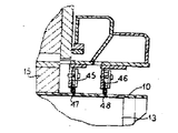
제3도는 단부와이퍼를 도시하기 위한 하다부위의 슈우(shoe)를 절단한 단면도.3 is a cross-sectional view of a shoe cut at one side for showing the end wiper;
제4도는 단부와이퍼의 다른 형태를 도시하는 제3도와 유사한 단면도.4 is a cross-sectional view similar to FIG. 3 showing another form of the end wiper;
제5도는 윤활제 와이퍼의 양호한 형태를 도시하는 확대 단면도.5 is an enlarged cross-sectional view showing a preferred form of a lubricant wiper.
제6도 내지 제8도는 윤활제 공급노즐의 3개의 형태를 도시하는 사시도.6 to 8 are perspective views showing three types of lubricant supply nozzles.
제9도는 윤활제 와이퍼 블레이드의 형태를 도시하는 사시도.9 is a perspective view showing the shape of the lubricant wiper blade.
제10도 내지 제12도는 벨트의 단부구조를 도시하는 단면도.10 to 12 are sectional views showing the end structure of the belt.
본 발명은 닙(mip)이 슈우(shoe)와 벨트사이에서 윤활유체의 유압필름을 지니는 슬라이딩 슈우에 의해형성되는 주행 섬유 웨브로부터 물을 탈수하는 확장된 닙 프레스에 관한 것이며, 특히 슈우의 벨트하부로 부터 윤활유체가 제거되도록 윤활 유체를 제어하고 유체가 벨트를 따라 함께 이송되지 못하게하며 유체가 웨브측면위의 벨트의 단부주위로 옮겨지지 않게하는 방법에 관한 것이다.FIELD OF THE INVENTION The present invention relates to an expanded nip press for dehydrating water from a traveling fiber web formed by a sliding shoe with a nip having a hydraulic film of lubricating fluid between the shoe and the belt, in particular the under belt of the shoe. To control the lubricating fluid so that the lubricating fluid is removed from the furnace, preventing the fluid from being transported along the belt and preventing the fluid from moving around the end of the belt on the side of the web.
종래의 제지기에서는, 웨브가 형성된후에, 웨브가 물이 섬유 웨브로 부터 기계적으로 탈수되는 프레스 부분을 통하여 이송된다. 프레스 부분은 종래의 2개의 로울프레스로부터 웨브가 간단한 2개의 로울프레스 보다 오랜시간 동안 연속적인 압력을 받는 긴 닙 프레스로 알려진 것으로 변경되었다. 이러한 긴 닙 프레스는 하나의 프레스 부재로서 하나의 로울을 지니며, 다른 프레스부재는 마찰을 제거하도록 벨트와 슈우 사이에 유압윤활제 필름을 발생시키고 웨브가 통과하는 프레스 영역을 가로질러 완전히 균일한 압력을 발생시키는 것을 조장하는 아치형 슬러이딩 슈우에 의해서 로울을 향하여 가압되는 연속적인 방수성 벨트이다. 이러한 개선된 슬라이딩 슈우프레스의 한 실시예는 이.제이.제스터스의 미합중국 특허 제3,783,097호와 모어등의 미합중국 특허원 제939,449호에 도시된다.In conventional paper machines, after the web is formed, the web is conveyed through a press portion where water is mechanically dewatered from the fibrous web. The press portion has been changed from the conventional two roll presses to what is known as a long nip press where the web is subjected to continuous pressure for longer than the simple two roll presses. This long nip press has one roll as one press member, the other press member generates a hydraulic lubricant film between the belt and the shoe to remove friction and applies a completely uniform pressure across the press area through which the web passes. It is a continuous waterproof belt that is pressed towards the roll by an arcuate sliding shoe that facilitates generation. One example of such an improved sliding shoe press is shown in U.S. Patent No. 3,783,097 to E. J. Zesters and U.S. Patent Application No. 939,449 to More.
슈우와 주행벨트 사이에 유압필름을 형성시키도록 공급되는 윤활유체의 웨브를 가로질러 균일하게 공급되어야 하고, 하나의 기계장치에서 이들이 구제되는 슈우의 안내단부로 오일과 같은 윤활유체를 공급하고, 슈우를 가로질러 완전하게 균일한 유압필름을 형성하도록 배치되고, 제어되는 일련의 노즐에 의해서 제공된다. 이러한 필름이 형성되면, 윤활제가 벨트에 붙어 슈우 후방으로 부터 주행해 나오는 벨트를 따라 함께 주행한다. 이러한 윤활유는 벨트가 안내로울위로 이송될때 벨트표면으로 부터 날아가도록 벨트의 표면 위를 따라서 계속 주행하지 않게 제어되어야 한다. 더우기, 윤활유는 이것이 벨트의 단부를 향하여 이송되지 못하고 이것이 주위공기로 날아가거나 벨트의 단부위를 통과하는 단부를 통과하지 못하고 웨브를 오염시키게 벨트의 웨브측면위로 이송되지 못하게 제어되어야 한다. 웨브는 펠트에 대해 이송되거나 2개의 펠트 사이로 이송되고 이러한 펠트는 웨브로부터 압착되는 탈수를 수용하게 유지되어야 하고, 만족스러운 작동은 윤활제가 그 탈수의 수용성에 영향을 주고 웨브를 오염시키게 펠트속으로 들어갈 수 없게되는 것을 요구한다.It is to be supplied evenly across the web of lubricating fluid supplied to form a hydraulic film between the shoe and the traveling belt, and in one machine supplies lubricating fluid, such as oil, to the guide end of the shoe from which they are rescued. It is arranged to form a completely uniform hydraulic film across and provided by a controlled series of nozzles. When such a film is formed, lubricant adheres to the belt and travels together along the belt running from behind the shoe. These lubricants should be controlled so that they do not continue to run along the surface of the belt so that it will fly from the belt surface when the belt is transported onto the guide roller. Moreover, the lubricating oil must be controlled such that it cannot be conveyed towards the end of the belt and it cannot fly over ambient air or pass over the end of the belt and pass over the web side of the belt to contaminate the web. The web is transported against the felt or between two felts and this felt must be kept to accommodate the dehydration being compressed from the web, and satisfactory operation will allow the lubricant to enter the felt to affect the water solubility of the dewatering and contaminate the web. It requires you to be unable to.
여러가지 장치가 벨트의 표면으로부터 윤활제를 제거하고 제어하게 시도되어 왔으나, 벨트가 분당 300 내지 5,000피이트의 속도로 주행하는 것이 문제가 되었다. 더우기, 표면을 가로질러 균일하게 제어되어야하므로 윤활제는 슈우와 벨트사이의 유압 필름속에서 유지되어야 하는 균일한 압력에 나쁜 영향을 주도록 벨트와 슈우사이의 닙속으로의 벨트 표면위로 귀환할 수 있도록 벨트와 함께 스트리크 또는 리지로 계속 이송되지 않게 된다.Various devices have been attempted to remove and control lubricant from the surface of the belt, but running the belt at speeds of 300 to 5,000 feet per minute has become a problem. Furthermore, since it must be uniformly controlled across the surface, the lubricant can be fed back onto the belt surface into the nip between the belt and the shoe to adversely affect the uniform pressure that must be maintained in the hydraulic film between the shoe and the belt. It will not continue to the streaks or ridges together.
또한, 단부를 따르는 특별한 완전한 제거는 윤활유가 주위부품으로 원심력에 의해서 흩어지고 벨트의 표면위의 단부위주로 이손되는 단부로 윤활유가 흩어져 나가는 것을 방지하게 이루어져야 한다.In addition, special complete removal along the end should be made to prevent the lubricant from scattering by centrifugal forces into the surrounding parts and by the end of which is displaced around the end of the belt.
기계작동의 다른 어려움은 최적설계의 벨트의 폭이 슈우의 폭 보다 넓다는 것이다. 이것은 슈우아래로 통과하는 가요성 벨트의 부분이 가압되고 가압되지 않은 슈우의 각각의 측면위의 벨트의 부분과 비교될때 이것이 슈우의 아래로부터 나오면 적은 두께가 된다는 것이다. 압축에 의해서 발생되는 이러한 두께의 차이는 슈우의 단부에서는 벨트의 표면을 가로지른 윤활유의 불균일한 밀도와 더불어 그 전체의 폭을 가로질러 벨트를 균일하게 처리하는 간단한 제거요소 부의 사용을 어렵게한다. 다시 말해서, 벨트가 슈우의 아래로부터 그속으로 통과해 나온후에 그 두께를 회복시키는데, 이러한 회복은 슈우의 주행단부 넘어서얼마간 떨어진 거리를 벨트가 주행한 후에야 이루어진다. 또한 벨트와 슈우사이에서 사용되는 윤활유가 슈우표면의 전체의 폭을 가로질러 균일해야 하고 윤활유의 최소량이 벨트로 부터 제거되고 벨트의 다른 표면위로 이송되고 웨브와 벨트를 오염시키는 벨트단부로 외부로 주행하는 초과오일을 회피하게 슈우의 단부위에 위치되어야 한다. 또한, 점성의 변화가 슈우와 벨트사이에서 압축되지 않는 단부의 오일과 반대로 슈우아래를 통과하는 윤활유에서 발생되는 열로 인하여 윤활유에서 발생한다.Another difficulty with machine operation is that the width of the belt of optimum design is wider than the width of the shoe. This means that when the portion of the flexible belt passing under the shoe is pressed against the portion of the belt on each side of the shoe that is pressurized and unpressurized, it is of less thickness when coming out of the shoe. This difference in thickness caused by compression makes it difficult to use a simple removal element portion at the end of the shoe that uniformly handles the belt across its entire width, along with the non-uniform density of lubricant across the surface of the belt. In other words, after the belt has passed through from underneath the shoe, its thickness is restored, and this recovery takes place only after the belt has traveled some distance beyond the running end of the shoe. In addition, the lubricant used between the belt and the shoe must be uniform across the entire width of the shoe surface, and the minimum amount of lubricant is removed from the belt, transferred over the other surface of the belt, and travels outward to the belt end, which contaminates the web and the belt. It should be located on the end of the shoe to avoid excess oil. In addition, a change in viscosity occurs in the lubricating oil due to the heat generated in the lubricating oil passing under the shoe as opposed to the oil at the end that is not compressed between the shoe and the belt.
따라서, 본 발명의 목적은 긴 닙 프레스의 슈우와 벨트사이의 유압 윤활 필름을 제공하는데 사용되는 윤활류의 제거 및 제어류 방법과 기계장치를 제공하는 것이다.It is therefore an object of the present invention to provide a method and mechanism for removing and controlling lubricating oils used to provide a hydraulic lubricating film between a shoe of a long nip press and a belt.
본 발명의 다른 목적은 고속의 긴 닙 프레스의 작업을 허락하고 윤활유가 펠트와 웨브를 이송하는 벨트의 표면위의 단부주위와 벨트의 단부 및 기계의 다른 부품에 흩어지고 도망가는 것을 방지하는 방법과 장치를 제공하는 것이다.Another object of the present invention is to permit the operation of a high speed long nip press and to prevent lubricating oil from scattering and running around the end of the belt and the end of the belt and other parts of the machine for conveying the felt and the web; To provide a device.
여기의 상응한 방법과 구조물 및 다른목적, 장점 및 특징이 본 발명의 원리에 따라 명세서, 청구범위 및 도면의 양호한 실시예와 연결하여 보다 명확하게 될 것이다. 제1도는 본 명세서에 참고로 사용된 미합중국 특허출원 제939,449호에 관련된 일반적인 형태의 연장된 닙프레스 제조를 예시하고 있다.Corresponding methods and structures herein and other objects, advantages and features will become more apparent in connection with the preferred embodiments of the specification, claims and drawings in accordance with the principles of the invention. FIG. 1 illustrates a general form of extended nip press manufacture in connection with US Patent Application No. 939,449, which is incorporated herein by reference.
본 프레스는 격리된 병렬 드라이브에 지지된 무단 불침투성 벨트(10)와 안내로울(11 및 12)을 포함하고 있다. 본 벨트는 제1프레스 및 제2프레스 닙(P1과 P2)을 형성하기 위해 두 개의 프레스로울(13과 14)위를 통과한다. 두개의 닙을 도시하는 특별한 배치가 2개의 닙을 통해 자동으로 운반된 벨트에 지지된 웨브(W)에 연속적인 닙의 장점을 제공하는 반면에, 사용된 원리는 상기에 참고된 특허 제3,783,097호에 도시된 것이며, 참고적으로 사용되었다. 제1도에서, 프레스 닙(P1)은 로울(13)과 벨트(1)사이에 형성되어 있으며 경사진 압력슈우(15)는 벨트의 경사표면의 반대에 놓여있고 내부 경사표면을 가지고 있으며 윤활유의 수력학적 필름은 벨트와 기름을 가진 슈우사이에서 제조되었는데, 이들은 슈우(15)의 안착된 안내단부 사이에 접착된 기름을 가진 슈우앞에 가로로 연장하는 연장된 노즐(20)에 의해 공급되어 진다.The press includes an endless
본 슈우는 로울 핀(18)에 지지되며 피스톤과 개략도에서(17)로 도시된 실린더 배열장치에 의해 벨트쪽으로 힘이 가해진다. 본 피스톤과 배열장치는 또한 제2프레스닙(P2)를 형성하기 위해 로울(14)을 향하여 가압하는 반대편 슈우(16)를 지지한다. 피스톤과 슈우 배열장치(17)는 피스톤과 실린더 조립체(17)에 의해 적용된 힘이 같고 힘의 제거를 위해 역작용하도록 로울 핀(19)의 벨트에 반대인 슈우를 가압한다.The shoe is supported by a
윤활유는 윤활액체의 필름이 슈우(16)와 벨트(10)사이에 제조되도록 노즐장치(21)를 통해 슈우(16)의 안내단부로 전달된다. 펠트(24)는 웨브로부터 나타난 물을 수용하기 위해 제1 프레스를 통해 통과한다. 펠트(25)는 웨브로부터 나온 물을 수용하기 위해 제2프레스를 통해 통과한다. 웨브(W)가 두 압력을 통해서 펠트에 운반되므로, 물이 섬유웨브로 부터 가압되고 펠트(24와 25) 속으로 이동되도록 슈우(15와 16)의 연장된 홈 아치형 표면의 길이 위에 압력을 가하기 쉽다. 슈우와 벨트사이의 수력학적인 필름을 제조하는 윤활유는 슈우의 트레일 단부에 벨트로 운반되며 로울(11과 12) 주위의 벨트로 운반되지 않고 벨트의 단부에서 떨어지지 않게하며 벨트의 웨브표면속의 벨트에지 주위로 이동되지 않도록 하기 위해 제거되어져야 한다.The lubricating oil is delivered to the guide end of the shoe 16 through the nozzle device 21 so that the film of the lubricating liquid is produced between the shoe 16 and the
벨트의 내부표면에서 윤활유의 제거를 위한 구조는(22와 23)으로 도시되었다. 윤활유의 제거용장치(22)는 표면으로 부터 기름을 섞는 벨트와 밀폐하여 접촉하는 안내단부를 가진 브레이드를 순서적으로 포함하고 있다. 본 기름은 도시안된 흡입노즐과 같은 기름제거 장치에 의해 제거된다.Structures for the removal of lubricant from the inner surface of the belt are shown at 22 and 23. The lubricating oil removal device 22 sequentially includes a braid having a guide end in hermetic contact with a belt for mixing oil from the surface. This oil is removed by an oil removal device such as a suction nozzle, not shown.
기름 제거장치(23)에 대해서, 브레이드(23a와 23b)는 벨트의 내부 경사표면과 밀폐하여 접촉하는 관계로 안내단부가 제공된다. 그리고 제거된 기름은 적당한 장치에 의해 담겨진다. 연장된 프레스는 5000 ft/min이상의 기계속도로 작동하며 슈우와 벨트사이의 수력학적인 필름을 형성하는 윤활유는 600Psi의 슈우 압력에서 작동한다. 기름은 벨트와 웨브사이의 일정한 프레스 압력을 유지하도록 도와주며 벨트의 닮는 것을 방지하기 위해 윤활유의 적당한 흐름을 제공한다. 그리고 기계폭의 매인치당 매분당 2-1갈론부피의 기름이 방지하기 위해 윤활유의 적당한 흐름을 제공한다. 그리고 기계폭의 매인치당 2-1갈론부피의 기름이 제공되는 것이 알려졌다. 이런기름의 양은 밀폐하여 인접한 새로이 형성된 웨브에 오염가능성을 줄이기 위해 제공되며 또한 제거된다.With respect to the
수력학적인 기름은 기름의 과잉이나 결핍의 위험성을 제공하지 않는 일정한 조절속도로 제공되어져야 한다. 슈우의 기름을 앞서서 제공하기 위한 노즐의 예는 제6도와 제7도 및 제8도에 도시되었다. 여기에 도시된 각 노즐은 벨트속의 전달장치로 흐르도록 연장한 노즐을 통해 기름을 챔버에 전달하는 기름공급이 제공된다. 제6도에 도시된 노즐장치는 더 양호한 형태이며 벨트로 기름을 전달하기 위한 연장된 연속 슬로트를 가지고 있다. 제7도의 장치는 기름의 전달을 위해 격리개구(34)의 계열을 가지고 있다. 제8도의장치는 이동벨트에 효과적인 와이어 형으로 유출하도록 갭 밑의 채널을 채우기 위해 하나의 열린 갭을 가지고 있다.Hydraulic oil should be provided at a constant rate of control that does not provide the risk of oil excess or deficiency. Examples of nozzles for providing the oil of the shoe earlier are shown in FIGS. 6 and 7 and 8. Each nozzle shown here is provided with an oil supply that delivers oil to the chamber through a nozzle that extends to flow into the delivery device in the belt. The nozzle arrangement shown in FIG. 6 is in a better form and has an extended continuous slot for delivering oil to the belt. The apparatus of FIG. 7 has a series of
인접 기계부분과 새로이 형성된 웨브로 기름의 누출을 방지하기 위해 약 95% 이상의 기름이 슈우 외측상의 벨트의 내부표면으로 부터 제거되어져야 한다. 기름제거용 양호한 장치는 벨트의 경사표면과 밀폐하여 접촉하는 관계로 자유안내 단부를 가진 휨 플라스틱 와이퍼 블레이드를 사용한다. 제너럴 일렉트릭 상표 '렉산'으로 판매되는 폴리카보네이트 플라스틱으로 형성된 플라스틱 볼레이드는 약 3인치의 길이를 가지고 두께가 0.2-0.6인치 인것으로 입증되었다. 블레이드의 탄성이 벨트와 접촉을 유지하도록 사용되는 구조의 양호한 형태는 제1 및 제2블레이드 (36과 37)가 블레이드 지지대(40)에서 고정되고 유지되는 제5도에 도시되었다. 안내단부(38과 39)는 벨트(10)의 경사표면과 경사지게 접촉한다. 블레이드가 제5도에 도시안된 노즐 형태의 이들 장치를 가진 벨트에 기름을 섞는 것 같이 블레이드의 내부표면 위로 밀려난 기름의 제거용 장치가 제공된다.At least about 95% of the oil must be removed from the inner surface of the belt on the outside of the shoe to prevent oil leakage into adjacent machine parts and newly formed webs. Preferred devices for oil removal use flexible plastic wiper blades with free guide ends in close contact with the inclined surface of the belt. Plastic balllaid, made of polycarbonate plastic sold under the General Electric trademark Lexan, has a length of about 3 inches and has proven to be 0.2-0.6 inches thick. A preferred form of the structure in which the elasticity of the blade is used to keep in contact with the belt is shown in FIG. 5 in which the first and
제2도는 다수의 이들 블레이드를 도시하는데, 이는 백(43)에 지지된(44)로 표시된 블레이드를 가진 조립체에 운반되어 있다. 부가적인 소수의 블레이드가 제공되거나 제1조립체에서 하류로 약간 공간이난 제2조립체는 블레이드의 안내단부가 돌출하여 벨트와 경사지게 접촉하도록 제공되어 각각 조절된다.2 shows a number of these blades, which are carried in an assembly with the blades labeled 44 supported by the
제3도와 제4도는 슈우(15)의 외부단부 외측으로 벨트와 경사지게 접촉하여 위치된 단부와이퍼를 도시하고 있다. 벨트(10)은 슈우(15)보다 더 넓으며 슈우단부의 밑에서 압착된 기름이 벨트 주위에서 가로로 이동하지 못하도록 벽(49와 50)에 지지된 세로와이퍼 블레이드(51,52)가 벨트 표면과 경사접촉으로 제공된다. 이들 블레이드(51과 52)는 슈우의 방향에서 내부로 돌출하여 벨트 표면에 상변하여 탄성적으로 압착하는 낮은 휨 단부를 가지고 있다.3 and 4 show an end wiper positioned in oblique contact with the belt outside the outer end of the
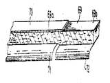
제4도는 홀드(45와 46)가 슈우(15)의 외부단부 외측에 있는 벨트(10)와 경사지게 접촉하여 낮은 단부에 있는 경사와이퍼(47과 48)를 운반하는 다른형태를 도시한다. 제3도와 제4도에서, 기술된 것 같이, 슈우밑을 통과하는 벨트의 부분이 압착되고, 슈우단부의 횡으로 외부측면 부분은 압축되지 않는다. 그 벨트를 매우 강인한 섬유성 고무물질로 형성되어 있으나, 600psi의 닙 압력에서 그 벨트의 압축이 일어나 슈우의 후단부 아래로부터 벗어나 있는 벨트의 부분이 슈우바로 아래에 위치하는 벨트의 부분보다 얇게된다. 윤활유는 가능한한 신속히 제거되어야하고, 그속에서 벨트는 그의 정상 두께를 회복하지 못한다. 그리하여, 제9도에 도시된 배치에서는, 와이퍼 블레이드가 여러 세그멘트들로 배치되고, 주 와이퍼 블레이드(71)는 벨트의 부분에 계합하도록 슈우의 폭과같다. 보조 와이퍼 블레이드(72)는 벨트의 비압축 지역에 계합한다. 그리하여 주 와이퍼 블레이드(71)는 그의 선단 날이 보조 와이퍼 블레이드(72)와 다른 수준에서 작동하여 벨트의 구께차에 적응하도록 한다. 제9도로 부터 볼 수 있는 바와 같이, 벨트의 부분(69a)은 압축되고 부분(69b)은 압축되지 않으며, 펠트(70)가 벨트(69)의 웨부 측부상에 도시되어 있다. 몇몇 경우, 벨트 연부주위에 묻어 있을 수 있는 윤활제를 제거하기 위해 펠트 옆의 지역의 벨트(69)의 웨부측상에 와이퍼 블레이드와 같은 수단이 설치되는 것이 바람직할 수도 있다.4 shows another form of holding 45 and 46 in oblique contact with the
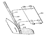
제10도 및 제12도에, 벨트의 웨브측상에 윤활제가 묻는 것을 방지하는 것을 보조하는 수단이 설치되어 있다. 제10도에서, 펠트(65)가 웨브를 지탱하고 있는 벨트(60)에 도시되어 있다. 벨트의 슈우표면상의 벨트의 연부에 종방향 홈(61)이 형성되어 있다. 그 홈은 그의 각측부에 측방면을 가지고 있고, 그 측방면은 오일이 벨트의 연부주위에서 측방으로 통과하는 것을 방지한다.In FIG. 10 and FIG. 12, a means is provided to assist in preventing lubricant from getting on the web side of the belt. In FIG. 10, a felt 65 is shown in the belt 60 carrying the web. The longitudinal grooves 61 are formed at the edges of the belt on the shoe surface of the belt. The groove has lateral sides at its sides, which prevent oil from passing laterally around the edge of the belt.
제11도의 장치는, 슈우의 외측 벨트 연부에 형성된 2개의 평형한 홈(63 및 64)과 펠트 (65)를 가진 벨트(62)를 이용한다. 제12도의 구조에서는, 벨트(65)는 슈우표면상의 홈(66)과 벨트의 웨브표면상의 부가홈(67)을 구비하고 있고, 그 양 홈들은 벨트 연부 주위에 윤활유가 묻어 웨브를 오염시키는 것을 방지하도록 작용한다.The apparatus of FIG. 11 uses a belt 62 having two
제5도에 도시한 바와 같은 작동에서, 벨트(10)는 유압윤활제 층을 지탱하고 있고, 그 윤활제는 얇고 탄성 및 가요성의 플라스틱 블레이드(36 및 37)에 의해 벨트로 부터 연속적으로 제거되며 수집된 윤활제는 흡인노즐에 의해 회수된다. 우수한 탈수효과를 가지고 분당 5000피이트까지의 속도로 연속작동이 핼해질 수 있다.In operation as shown in FIG. 5, the
Claims (1)
Applications Claiming Priority (2)
| Application Number | Priority Date | Filing Date | Title |
|---|---|---|---|
| US06/115,010 US4308096A (en) | 1980-01-24 | 1980-01-24 | Extended nip press |
| US115010 | 1980-01-24 |
Publications (2)
| Publication Number | Publication Date |
|---|---|
| KR830005435A KR830005435A (en) | 1983-08-13 |
| KR850000454B1 true KR850000454B1 (en) | 1985-04-05 |
Family
ID=22358796
Family Applications (1)
| Application Number | Title | Priority Date | Filing Date |
|---|---|---|---|
| KR1019810000231A KR850000454B1 (en) | 1980-01-24 | 1981-01-24 | Extended nip press |
Country Status (17)
| Country | Link |
|---|---|
| US (1) | US4308096A (en) |
| EP (1) | EP0033293B1 (en) |
| JP (1) | JPS5922837B2 (en) |
| KR (1) | KR850000454B1 (en) |
| AU (1) | AU536382B2 (en) |
| BR (1) | BR8106527A (en) |
| CA (1) | CA1136463A (en) |
| DE (1) | DE3172176D1 (en) |
| ES (1) | ES499381A0 (en) |
| FI (1) | FI77285C (en) |
| GB (2) | GB2068431B (en) |
| IN (1) | IN152292B (en) |
| NO (1) | NO153979C (en) |
| PH (1) | PH16305A (en) |
| SU (1) | SU1429944A3 (en) |
| WO (1) | WO1981002173A1 (en) |
| ZA (1) | ZA81534B (en) |
Families Citing this family (11)
| Publication number | Priority date | Publication date | Assignee | Title |
|---|---|---|---|---|
| US5238537A (en) * | 1981-09-15 | 1993-08-24 | Dutt William H | Extended nip press belt having an interwoven base fabric and an impervious impregnant |
| US5234551A (en) * | 1981-09-24 | 1993-08-10 | Dutt William H | Extended nip press belt having an interwoven base fabric and an impervious impregnant |
| DE3317456C2 (en) * | 1983-04-02 | 1993-12-02 | Voith Gmbh J M | Belt press unit for dewatering fibrous webs |
| US4536255A (en) * | 1983-12-07 | 1985-08-20 | Beloit Corporation | Extended nip press |
| US4643775A (en) * | 1984-06-29 | 1987-02-17 | Crown Zellerbach Corporation | Fabric conditioning and cleaning system |
| DE19623652A1 (en) * | 1996-06-13 | 1997-12-18 | Voith Sulzer Papiermasch Gmbh | Deflection adjustment roller |
| DE19703966A1 (en) * | 1997-02-03 | 1998-08-06 | Voith Sulzer Papiermasch Gmbh | Belt press unit with fluid wiping device and method for operating the belt press unit |
| DE19828156A1 (en) * | 1998-06-24 | 1999-12-30 | Voith Sulzer Papiertech Patent | Device for smoothing a web of material |
| SE515573C2 (en) * | 1999-11-26 | 2001-09-03 | Valmet Karlstad Ab | Method and apparatus for oil evacuation from a shoe press unit |
| FI119069B (en) * | 2005-02-23 | 2008-07-15 | Metso Paper Inc | Arrangement with press section of web forming machine |
| EP2327834B1 (en) | 2009-11-26 | 2012-06-27 | Metso Paper Inc. | Arrangement and method for removing oil from a shoe press in a fiber web machine |
Family Cites Families (5)
| Publication number | Priority date | Publication date | Assignee | Title |
|---|---|---|---|---|
| US3783097A (en) * | 1972-05-30 | 1974-01-01 | Beloit Corp | Hydrodynamically loaded web press with slipper bearing shoes |
| US3839147A (en) * | 1973-03-22 | 1974-10-01 | Beloit Corp | Fibrous web press nip structure including nonporous belts backed by fluid pressure chambers having flexible sills |
| IT1029565B (en) * | 1974-07-22 | 1979-03-20 | Baroni Fausto | APPARATUS FOR PROCESSING A PAPER TAPE |
| FI772143A (en) * | 1977-07-08 | 1979-01-09 | Tampella Oy Ab | LAONGZONSPRESS FOER PAPER MACHINE |
| US4201624A (en) * | 1978-09-05 | 1980-05-06 | Beloit Corporation | Extended nip press |
-
1980
- 1980-01-24 US US06/115,010 patent/US4308096A/en not_active Expired - Lifetime
-
1981
- 1981-01-22 GB GB8102003A patent/GB2068431B/en not_active Expired
- 1981-01-22 EP EP81630007A patent/EP0033293B1/en not_active Expired
- 1981-01-22 DE DE8181630007T patent/DE3172176D1/en not_active Expired
- 1981-01-23 ES ES499381A patent/ES499381A0/en active Granted
- 1981-01-23 AU AU67839/81A patent/AU536382B2/en not_active Ceased
- 1981-01-23 WO PCT/US1981/000088 patent/WO1981002173A1/en unknown
- 1981-01-23 BR BR8106527A patent/BR8106527A/en unknown
- 1981-01-23 JP JP56008086A patent/JPS5922837B2/en not_active Expired
- 1981-01-23 PH PH25125A patent/PH16305A/en unknown
- 1981-01-23 FI FI810183A patent/FI77285C/en not_active IP Right Cessation
- 1981-01-24 KR KR1019810000231A patent/KR850000454B1/en active
- 1981-01-26 ZA ZA00810534A patent/ZA81534B/en unknown
- 1981-01-26 CA CA000369286A patent/CA1136463A/en not_active Expired
- 1981-01-29 IN IN100/CAL/81A patent/IN152292B/en unknown
- 1981-09-22 NO NO813214A patent/NO153979C/en unknown
- 1981-09-23 SU SU813340724A patent/SU1429944A3/en active
-
1984
- 1984-03-22 GB GB08407426A patent/GB2138457B/en not_active Expired
Also Published As
| Publication number | Publication date |
|---|---|
| CA1136463A (en) | 1982-11-30 |
| ES8205907A1 (en) | 1982-07-01 |
| DE3172176D1 (en) | 1985-10-17 |
| NO153979B (en) | 1986-03-17 |
| ZA81534B (en) | 1982-02-24 |
| US4308096A (en) | 1981-12-29 |
| PH16305A (en) | 1983-09-05 |
| GB2138457A (en) | 1984-10-24 |
| FI77285C (en) | 1990-05-29 |
| KR830005435A (en) | 1983-08-13 |
| GB8407426D0 (en) | 1984-05-02 |
| AU6783981A (en) | 1981-08-17 |
| JPS56107097A (en) | 1981-08-25 |
| NO813214L (en) | 1981-09-22 |
| IN152292B (en) | 1983-12-17 |
| EP0033293B1 (en) | 1985-09-11 |
| AU536382B2 (en) | 1984-05-03 |
| GB2068431A (en) | 1981-08-12 |
| GB2068431B (en) | 1985-04-03 |
| FI810183L (en) | 1981-07-25 |
| BR8106527A (en) | 1981-12-01 |
| WO1981002173A1 (en) | 1981-08-06 |
| FI77285B (en) | 1988-10-31 |
| EP0033293A1 (en) | 1981-08-05 |
| GB2138457B (en) | 1985-05-09 |
| NO153979C (en) | 1986-06-25 |
| JPS5922837B2 (en) | 1984-05-29 |
| ES499381A0 (en) | 1982-07-01 |
| SU1429944A3 (en) | 1988-10-07 |
Similar Documents
| Publication | Publication Date | Title |
|---|---|---|
| KR850000454B1 (en) | Extended nip press | |
| FI71369B (en) | LAONGNYPPRESS FOER PAPER MASK | |
| KR900002103B1 (en) | Enclosed shoe press | |
| FI70952B (en) | ANORDNING MED LAONG PRESON VID PRESSBEHANDLING AV FIBERBANA | |
| SU1072820A3 (en) | Pressing apparatus with elongated pressing zone for removing liquid from moving web of fibrous material | |
| KR860001624B1 (en) | Extended nip shoe | |
| US3748225A (en) | Fibrous web press nip structure including nonporous belts backed by pistons supported with fluid pressure | |
| FI91789B (en) | Paper machine long zone press | |
| CA2114469C (en) | An arrangement in a dryer for a fibre web | |
| JP3582548B2 (en) | Apparatus for applying liquid or pasty material to a moving material web | |
| KR860001618B1 (en) | Extended nip press | |
| US4398997A (en) | Extended nip press | |
| FI65104C (en) | PROCEDURE FOR IMPROVING VIDEO PRESS PROCESSING IN FIBER STATION AND PAPER-ELLER CARTON | |
| US4861430A (en) | Controlling a paper web path in the press section with an impermeable belt | |
| KR840005847A (en) | Press mechanism | |
| FI119944B (en) | Method for sealing and / or lubricating a border ruler in a sheet forming machine, sheet forming machine and border ruler arrangement for a sheet forming machine | |
| KR950014935B1 (en) | Web transfer device | |
| SE463135B (en) | MACHINE FOR APPLYING GLUE ON A SIDE OF A MATERIAL COVER | |
| US3647621A (en) | Roller press especially a washing press for paper machine felts having a floating roller | |
| JPH07196234A (en) | Method and device to separate running wet paper from two wire belts | |
| US5647960A (en) | Press section and method for starting and operating thereof | |
| US1430166A (en) | Stripping means for pressure rolls | |
| JP5000388B2 (en) | Method and apparatus for suppressing rewetting of wet paper | |
| KR820001520B1 (en) | Web transfer system |