KR840002482B1 - Method of power generation by supercharged internal combustion engine - Google Patents
Method of power generation by supercharged internal combustion engine Download PDFInfo
- Publication number
- KR840002482B1 KR840002482B1 KR1019810000939A KR810000939A KR840002482B1 KR 840002482 B1 KR840002482 B1 KR 840002482B1 KR 1019810000939 A KR1019810000939 A KR 1019810000939A KR 810000939 A KR810000939 A KR 810000939A KR 840002482 B1 KR840002482 B1 KR 840002482B1
- Authority
- KR
- South Korea
- Prior art keywords
- compressed air
- compressor
- gas
- engine
- turbine
- Prior art date
Links
- 238000000034 method Methods 0.000 title claims abstract description 9
- 238000002485 combustion reaction Methods 0.000 title claims description 18
- 238000010248 power generation Methods 0.000 title 1
- 239000007789 gas Substances 0.000 claims abstract description 82
- 230000006835 compression Effects 0.000 claims description 11
- 238000007906 compression Methods 0.000 claims description 11
- 238000005086 pumping Methods 0.000 claims description 2
- 230000008878 coupling Effects 0.000 abstract description 2
- 238000010168 coupling process Methods 0.000 abstract description 2
- 238000005859 coupling reaction Methods 0.000 abstract description 2
- 239000012530 fluid Substances 0.000 description 16
- 238000001816 cooling Methods 0.000 description 9
- 238000010438 heat treatment Methods 0.000 description 8
- 230000009471 action Effects 0.000 description 4
- 239000000567 combustion gas Substances 0.000 description 4
- 239000000203 mixture Substances 0.000 description 4
- 230000008901 benefit Effects 0.000 description 3
- 230000000694 effects Effects 0.000 description 3
- 238000011084 recovery Methods 0.000 description 3
- 230000007423 decrease Effects 0.000 description 2
- 230000009347 mechanical transmission Effects 0.000 description 2
- 230000004048 modification Effects 0.000 description 2
- 238000012986 modification Methods 0.000 description 2
- 230000001105 regulatory effect Effects 0.000 description 2
- 230000001133 acceleration Effects 0.000 description 1
- 239000002131 composite material Substances 0.000 description 1
- 239000002826 coolant Substances 0.000 description 1
- 230000001419 dependent effect Effects 0.000 description 1
- 238000010586 diagram Methods 0.000 description 1
- 239000000446 fuel Substances 0.000 description 1
- 238000002347 injection Methods 0.000 description 1
- 239000007924 injection Substances 0.000 description 1
- 239000007788 liquid Substances 0.000 description 1
- 210000000056 organ Anatomy 0.000 description 1
- 230000008569 process Effects 0.000 description 1
- 230000009467 reduction Effects 0.000 description 1
- 230000001172 regenerating effect Effects 0.000 description 1
- 238000003303 reheating Methods 0.000 description 1
- 230000003584 silencer Effects 0.000 description 1
Images


Classifications
-
- F—MECHANICAL ENGINEERING; LIGHTING; HEATING; WEAPONS; BLASTING
- F02—COMBUSTION ENGINES; HOT-GAS OR COMBUSTION-PRODUCT ENGINE PLANTS
- F02B—INTERNAL-COMBUSTION PISTON ENGINES; COMBUSTION ENGINES IN GENERAL
- F02B37/00—Engines characterised by provision of pumps driven at least for part of the time by exhaust
- F02B37/12—Control of the pumps
- F02B37/20—Control of the pumps by increasing exhaust energy, e.g. using combustion chamber by after-burning
-
- F—MECHANICAL ENGINEERING; LIGHTING; HEATING; WEAPONS; BLASTING
- F01—MACHINES OR ENGINES IN GENERAL; ENGINE PLANTS IN GENERAL; STEAM ENGINES
- F01N—GAS-FLOW SILENCERS OR EXHAUST APPARATUS FOR MACHINES OR ENGINES IN GENERAL; GAS-FLOW SILENCERS OR EXHAUST APPARATUS FOR INTERNAL COMBUSTION ENGINES
- F01N5/00—Exhaust or silencing apparatus combined or associated with devices profiting by exhaust energy
- F01N5/02—Exhaust or silencing apparatus combined or associated with devices profiting by exhaust energy the devices using heat
-
- F—MECHANICAL ENGINEERING; LIGHTING; HEATING; WEAPONS; BLASTING
- F02—COMBUSTION ENGINES; HOT-GAS OR COMBUSTION-PRODUCT ENGINE PLANTS
- F02B—INTERNAL-COMBUSTION PISTON ENGINES; COMBUSTION ENGINES IN GENERAL
- F02B37/00—Engines characterised by provision of pumps driven at least for part of the time by exhaust
- F02B37/04—Engines with exhaust drive and other drive of pumps, e.g. with exhaust-driven pump and mechanically-driven second pump
- F02B37/10—Engines with exhaust drive and other drive of pumps, e.g. with exhaust-driven pump and mechanically-driven second pump at least one pump being alternatively or simultaneously driven by exhaust and other drive, e.g. by pressurised fluid from a reservoir or an engine-driven pump
- F02B37/105—Engines with exhaust drive and other drive of pumps, e.g. with exhaust-driven pump and mechanically-driven second pump at least one pump being alternatively or simultaneously driven by exhaust and other drive, e.g. by pressurised fluid from a reservoir or an engine-driven pump exhaust drive and pump being both connected through gearing to engine-driven shaft
-
- F—MECHANICAL ENGINEERING; LIGHTING; HEATING; WEAPONS; BLASTING
- F02—COMBUSTION ENGINES; HOT-GAS OR COMBUSTION-PRODUCT ENGINE PLANTS
- F02B—INTERNAL-COMBUSTION PISTON ENGINES; COMBUSTION ENGINES IN GENERAL
- F02B37/00—Engines characterised by provision of pumps driven at least for part of the time by exhaust
- F02B37/12—Control of the pumps
- F02B37/16—Control of the pumps by bypassing charging air
- F02B37/168—Control of the pumps by bypassing charging air into the exhaust conduit
-
- Y—GENERAL TAGGING OF NEW TECHNOLOGICAL DEVELOPMENTS; GENERAL TAGGING OF CROSS-SECTIONAL TECHNOLOGIES SPANNING OVER SEVERAL SECTIONS OF THE IPC; TECHNICAL SUBJECTS COVERED BY FORMER USPC CROSS-REFERENCE ART COLLECTIONS [XRACs] AND DIGESTS
- Y02—TECHNOLOGIES OR APPLICATIONS FOR MITIGATION OR ADAPTATION AGAINST CLIMATE CHANGE
- Y02T—CLIMATE CHANGE MITIGATION TECHNOLOGIES RELATED TO TRANSPORTATION
- Y02T10/00—Road transport of goods or passengers
- Y02T10/10—Internal combustion engine [ICE] based vehicles
- Y02T10/12—Improving ICE efficiencies
Landscapes
- Engineering & Computer Science (AREA)
- Chemical & Material Sciences (AREA)
- Combustion & Propulsion (AREA)
- Mechanical Engineering (AREA)
- General Engineering & Computer Science (AREA)
- Supercharger (AREA)
Abstract
Description
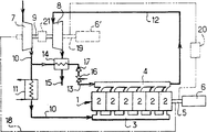
제1도는 본 발명을 이용하는 대부분의 경우를 나타낸 도해도.1 is a diagram showing most cases of using the present invention.
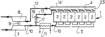
제2도는 본 발명에 의한 동력 발생장치의 기본원리를 밝힌 전체도.2 is a general view showing the basic principle of the power generator according to the present invention.
제3도는 본 발명을 표준형 펄스변환기형 배기다기관과 2단과급장치로 된 내연기관에 이용한 변형예.3 is a modification in which the present invention is used for an internal combustion engine consisting of a standard pulse converter type exhaust manifold and a two-stage supercharger.
제4도는 본 발명을 표준형 펄스변환기형 배기다기관과 2단과급장치로 된 내연기관에 이용한 또 다른 변형예.4 is another modified example using the present invention for an internal combustion engine comprising a standard pulse converter type exhaust manifold and a two-stage supercharger.
제5도는 표준형 펄스 변환기를 열교환기속에 일체로 결합시킨 형태의 배기다기관을 갖춘 내연기관으로 된 본 발명의 또다른 예.5 is another example of the present invention of an internal combustion engine having an exhaust manifold in which a standard pulse converter is integrally coupled to a heat exchanger.
제6도는 분기된 압축공기 흐름이 내연기관의 최소한 한개의 배기밸브를 식히는데 사용됨으로서 가열되는 본 발명의 또 다른 예.6 is another example of the invention in which branched compressed air flows are heated as they are used to cool at least one exhaust valve of the internal combustion engine.
제7도는 분기된 압축공기흐름이 배기가스로 추진되는 최소한 하나의 터어빈에서 흘러나오는 개스의 일부로 된 적어도 한개의 분사기 또는 그와 같은 것속에 있는 혼합물에 의해서 열에너지를 받는 동시에 대량 공급되는 것을 나타낸 본 발명의 또 다른 예.FIG. 7 shows that the branched compressed air flow is supplied in bulk and at the same time receiving thermal energy by at least one injector or mixture in such part of the gas flowing out of at least one turbine driven by exhaust gas. Another example of
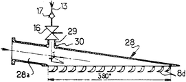
제8-10도는 분기된 압축공기 흐름이 배기가스로 구동되는 최소한 한개의 터어빈의 와류형 유입실 속으로 주입되어 들어가는 것을 나타낸 본 발명의 특정예로서,8-10 are specific examples of the invention showing that branched compressed air flow is injected into the vortex inlet chamber of at least one turbine driven by exhaust gas,
제8도는 와류실의 외부 측면도.8 is an external side view of the vortex chamber.
제9도는 제8도의 선(Ⅸ-IX)에 따라서 취한 단면도.FIG. 9 is a sectional view taken along the line VII-IX of FIG. 8; FIG.
제10도는 와류실은 360°평면으로 펼쳐서 나타낸 부분 단면도.10 is a partial cross-sectional view showing the swirl chamber unfolded in a 360 ° plane.
본 발명은 동력발생장치를 통하여 에너지를 발생시키는 방법에 관한 것으로서 동력발생 장치는, 한정하는 것은 아니지만, 특히 디젤기관과 같은 왕복 운동하는 피스톤을 지닌 용적형 내연기관과, 과급용 공기 압축장치와, 배기가스로 작동되는 터보 모터장치(turbomotor system)로 언급될 터보축 구동기관 장치등으로 구성되며 상기 세 장치들 사이에 기계식 및 또는 공압식 또는 유압식 연결장치가 있다.The present invention relates to a method for generating energy through a power generator, which includes, but is not limited to, a volumetric internal combustion engine having a reciprocating piston such as a diesel engine, a supercharged air compressor, It consists of a turboshaft drive engine system, which will be referred to as a turbomotor system operated with exhaust gas, and there is a mechanical and / or pneumatic or hydraulic connection between the three devices.
이 기술분야에서 이미 공지된바 특히 프랑스 특허 제75,12744호(2,308,785)의 동력발생장치는 특히 왕복운동을 하는 피스톤과 압축점화되는 체적비 또는 압축비가 작은 4행정 디젤기관과 같은 내연기관을 갖추고서 하나 또는 여러개의 케이징 및 / 또는 여러개의 터어빈 및/ 또는 최종 공냉장치와 일련의 케이징들 또는 단(stages)들 사이에는 중간 공냉장치가 있는 압축단을 지닌 터보-압축기에 의해 공기가 과급되도록 되어 있는데, 터어빈이 기관으로부터 배기가스를 받아서 기계식 연결축을 통해 압축기를 구동시키도록 되어 있다. 그 기관의 흡입구와 배출구 사이에는 일반적으로 기관작동중에 영구히 개방된 우회도관이 설치되어 기관에 흡입되지 못한 공기를 모두 압축기로부터 터어빈으로 우회시키도록 되어 있는데, 우회된 공기는 터어빈 유입구 앞쪽에서 기관의 배기다기관에서 나온 배기가스와 합쳐져서 배기가스에 의해 공급되는 열로 가열된다. 이러한 가열은 한편으로는 터어빈으로부터 흘러나오는 가스흐름과, 다른 한편으로는 압축기로부터 흘러나와서 기관과 우회도관쪽으로 향하여 흐르는 공기 사이의 열교환기를 통한 열회전에 의해서 저출력 작동중에 공기를 재가열시킴으로써 이루어진다. 따라서 이 열교환기는 압축기의 송출도관 속에 삽입되고, 공기냉각기는 열교환기에서 흘러나와 기관의 흡기다기관을 향하여 흐르는 공기의 통로 속에 삽입된다.The power generating apparatus already known in the art, in particular in French Patent No. 75,12744 (2,308,785), in particular has internal combustion engines such as reciprocating pistons and four-stroke diesel engines with low compression or ignition volume or compression ratios. To supercharge the air by means of a turbo-compressor having a compression stage with an intermediate air cooling system between one or several casings and / or several turbines and / or the final air cooling system and a series of casings or stages. The turbine receives exhaust gas from the engine and drives the compressor via a mechanical coupling shaft. Between the inlet and the outlet of the engine is usually a bypass conduit that is permanently open during engine operation so that any air that has not been sucked into the engine is diverted from the compressor to the turbine, which is the exhaust of the engine in front of the turbine inlet. It is combined with the exhaust gas from the engine and heated by the heat supplied by the exhaust gas. This heating is accomplished by reheating the air during low power operation by means of a thermal rotation between the gas stream flowing out of the turbine on the one hand and the air flowing out of the compressor on the other hand and flowing towards the bypass and conduit. The heat exchanger is thus inserted into the delivery conduit of the compressor and the air cooler is inserted into the passage of air flowing out of the heat exchanger and towards the intake manifold of the engine.
따라서, 이 우회도관은 그 기관과 공기냉각기(대기나 또는 기관냉각수나 액체의 강제순환에 의해 냉각됨)에 평행하게 분기되어 있다. 상술한 열교환기는 가열시켜야 할 유체와 가열된 유체를 섞지 않는 즉 두개의 독립회로를 갖춘 형태의 것(예컨대 판형 또는 관형 열교환기)이다.Thus, this bypass conduit is branched parallel to the engine and the air cooler (cooled by air or forced circulation of engine coolant or liquid). The heat exchanger described above is of a type that does not mix the fluid to be heated with the heated fluid, i.e., with two independent circuits (eg, plate or tubular heat exchanger).
이 우회도관에는, 사실상 우회도관의 압력에 따라 좌우되는 압력차를 압축기 출구와 터빈 입구 사이에 제공하도록 자동적으로 조절되는 가변형 자유통로 단면을 지닌 유량조절장치가 제공되어 있다. 열교환기에서 나오는 가스는 외기로 빠져나간다. 고출력 작동중에는 기관 배기가스 에너지가 터어빈을 구동시킬 수 있을만큼 충분하다. 기관이 정격속도로 작동하고 있을때, 압축기는 기관에 흡입되는 공기유량에 더하여, 공기 순환으로 기관의 뜨거운 부분들을 냉각시킴과 아울러 특히 터빈입구와 압축기 출구 사이에 한정된 압력차를 유지하도록 하는 공기유량을 공급하도록 터보-압축기는 기관과 연결된다.This bypass conduit is provided with a flow regulating device having a variable free passage section which is automatically adjusted to provide a pressure difference between the compressor outlet and the turbine inlet which is in fact dependent on the pressure of the bypass conduit. The gas from the heat exchanger escapes to the outside air. During high power operation, the engine exhaust energy is sufficient to drive the turbine. When the engine is running at rated speed, the compressor is capable of cooling the hot parts of the engine with air circulation, in addition to the air intake into the engine, and in particular maintaining a limited pressure differential between the turbine inlet and the compressor outlet. The turbo-compressor is connected with the engine to supply.
아울러 이 공지의 장치에는 터어빈의 앞쪽에 보조연소실이 장치되어 우회도관에서 흘러나오는 공기는 물론 기관배기가스까지도 받아서 터보-압축기로 하여금 자동조절되게 함과 동시에 그 기관의 운전속도에 관계없이 특히 기관이 정지하고 있을때에도 그 기관과는 별도로 작동하도록 한다.In addition, this well-known device is equipped with an auxiliary combustion chamber in front of the turbine to receive not only the air flowing out of the bypass conduit but also the engine exhaust gas so that the turbo-compressor is automatically regulated and the engine is operated regardless of the operating speed of the engine. Operate separately from the engine even when stationary.
그러나, 이러한 공지의 장치는 특히 다음과 같은 단점을 내포하고 있다.However, these known devices in particular have the following disadvantages.
-터어빈으로부터 나오는 가스로부터 열회수를 통하여 터어빈으로의 에너지 공급은 우회된 압축공기 흐름에 일부가 전달되고 나머지는 공기냉각기를 거쳐서 기관의 흡기다기관에 공급되는 과급용 압축공기에 가해지기 때문에 에너지 소비 또는 사용에 손실이 크다.The energy supply to the turbine through the heat recovery from the gas from the turbine is partially transferred to the bypassed compressed air stream and the rest is applied to the supercharged compressed air supplied to the engine's intake manifold via an air cooler, thus consuming or using energy. The loss is great.
-보조연소실로 인하여 연료가 더 들기 때문에 에너지 비용이 더욱 많이 든다.Secondary combustion chambers use more fuel, resulting in higher energy costs.
-특히, 기관의 배기다기관과 터어빈의 가스유입구 사이에 삽입되어 우회된 압축공기 흐름을 수용하는 연소실과 아울러, 아회도관속의 조절장치를 이루는 밸브와 같은 기본적인 성분요소의 피이드백(feedback)제어장치의 구조적인 복합성으로 인하여 전체 장치의 비용을 상당히 증가시킴은 물론 동작의 신뢰도 또는 안전도를 떨어뜨린다. 따라서, 본 발명의 주된 목적은 상술한 공지의 장치의 장점은 그대로 유지시키면서도 상술한 단점을 제거하거나 또는 적어도 극복하는데에 있다. 즉 :In particular, a feedback chamber is provided between the exhaust manifold of the engine and the gas inlet of the turbine to receive the bypassed compressed air flow, as well as the feedback control devices of the basic components, such as valves, which constitute the regulator of the ash pipe. Due to its structural complexity, the cost of the overall device is significantly increased, as well as the reliability or safety of operation. Therefore, the main object of the present invention is to eliminate or at least overcome the above-mentioned disadvantages while maintaining the advantages of the above-described known apparatus. In other words :
-저속운전에서 큰 추력을 얻을 수 있도록 기관의 사용작동범위를 확장시킴 :Extends the operating range of the engine to achieve greater thrust in low speed operation:
-공기압축기의 정격조작점을 고효율대의 헌팅한계(huntinglimit)쪽으로 가능한 더욱 근접시킴. 이 목적으로 본 발명은 공지의 장치에서와 같이 압축장치와 용적형 동력장치 사이에서 그 압축장치에 의해서 송출된 총압축 공기흐름으로부터 압축공기 흐름을 우회시켜 뽑아내어 터보-모터장치의 가스출구 앞의 상술한 용적형 동력장치의 작동실린더의 가스출구 사이에서 그 용적형 동력장치의 배기가스로 흘러보냄과 아울러 용적형 동력장치 속에서 연소된 가스에 의해 전달된 에너지로부터 회수된 에너지를 우회된 압축공기 흐름작용을 통해 배기가스로 공급하는 것으로 구성된 형태의 방법을 이용한다.-Move the air compressor's rated operating point closer to the hunting limit of the high-efficiency band. To this end, the present invention, as is known in the art, bypasses the compressed air flow from the total compressed air flow sent out by the compressor between the compressor and the volumetric power unit, and in front of the gas outlet of the turbo-motor apparatus. Compressed air bypasses the energy recovered from the energy delivered by the gas burned in the volumetric power unit between the gas outlets of the above-described volumetric power unit and the working gas outlet of the volumetric power unit. It uses a method of the form consisting of supplying exhaust gas through the flow action.
본 발명은 상기 방법을 다음과 같이 개선시킴으로써, 즉 그러한 에너지를 열교환기를 거치지 않고 바로 직접 우회된 압축기류의 최소한 대부분으로만 독점적으로 공급시킴으로써 상술한 기술적인 문제들을 해결한다.The present invention solves the above technical problems by improving the process as follows, i.e. supplying such energy exclusively to at least a majority of the compressors directly bypassed without passing through a heat exchanger.
이하 본문에서는 전술한 장치 개념들에 대하여 다음과 같이 정의한다.In the following text, the aforementioned device concepts are defined as follows.
-용적형 동력장치는 하나이상의 내연기관으로 구성된다.Volumetric power units consist of one or more internal combustion engines.
-압축기 장치는 한개 이상의 압축기를 포함한다.The compressor device comprises one or more compressors.
-터보 모터 또는 터보축 기관장치는 최소한 한개의 배기가스로 구동되는 터어빈, 따라서 한개 이상의 터어빈을 포함한다.The turbo motor or turboshaft engine comprises at least one exhaust driven turbine and thus at least one turbine.
본 발명에 따라서, 또한 상술한 공지의 장치에서와 같이 우회된 압축공기 흐름은 터보 모터장치의 입구 압쪽에서 용적형 동력장치의 배기가스와 합류한다. 본 발명의 다른 특징에 따라서 압축기 장치의 최소한 한 압축기로부터 흘러나옴은 물론 개별적으로 에너지를 공급받은 상기 우회된 압축공기 흐름은, 적어도 하나의 배기가스 수집통로의 순간 최대압력이 압축공기 흐름을 역류시키지 않을 정도로 낮은 지점에, 바람직하기로는 그 압력이 가능한 일정한 지점에 또는 배기가스용의 적어도 하나의 한정된 흐름통로 지점에서 용적형 동력장치의 최소한 한개의 내연기관의 배기가스에 가해진다.According to the invention, the bypassed compressed air stream also merges with the exhaust gas of the volumetric power unit at the inlet pressure side of the turbo motor unit, as in the above known arrangement. According to another feature of the invention, the bypassed compressed air stream, which is separately energized from at least one compressor of the compressor unit, is such that the instantaneous maximum pressure of the at least one exhaust gas collection passage does not reverse the compressed air flow. At a point that is too low, preferably the pressure is applied to the exhaust gas of at least one internal combustion engine of the volumetric power plant at a fixed point where possible or at least one defined flow passage point for the exhaust gas.
본 발명에 따른 방법을 실시하는 바람직한 방식에 의하면, 본 발명은 터보 모터장치로부터 나오는 가스흐름의 최소한 대부분과 압축기 장치에서 나오는 압축공기 흐름 사이의 공기를 가열시킴에 의한 열교환을 통해서 그 터보 모터장치의 배기가스로부터 열의 형태로 공급된 에너지를 이용하지만, 본 발명의 또 다른 특징에 의하면 그러한 열교환은 우회된 압축공기 흐름의 최소한 대부분에 대하여 이루어진다.According to a preferred way of carrying out the method according to the invention, the invention provides for the use of the turbo motor apparatus through heat exchange by heating air between at least the majority of the gas flow coming from the turbo motor apparatus and the compressed air flow from the compressor apparatus. While utilizing the energy supplied in the form of heat from the exhaust gas, according to another feature of the invention such heat exchange takes place for at least the majority of the bypassed compressed air stream.
전술한 기본적인 특징에 사용한 기본원리에 의해서 본 발명은 터보-모터장치와 압축기 장치에 의해 각기 공급되는 압력이 떨어지거나 또는 바람직하게 충분치 못한 작동범위(저속에서 고추력)로 그 작동점이 더욱 근접될수록 터보-모터장치의 출구에서의 기체온도는 더 높아지고, 따라서 자연히 배기가스로부터 회수되는 에너지의 포렌셜을 더욱 증가시켜 상당한 잇점을 제공한다. 따라서, 본 발명은 전체장치의 구조와 그 피이드백 제어장치의 구조를 매우 단순화시키기 때문에 상당한 잇점을 얻을 수 있다.According to the basic principle used for the above-described basic features, the present invention provides the turbo as the operating point becomes closer to the operating range (low speed and high thrust force), or the pressure supplied by the turbo-motor device and the compressor device, respectively, is not sufficient. The gas temperature at the outlet of the motor device is higher, thus naturally increasing the potential of the energy recovered from the exhaust gas, which provides a significant advantage. Thus, the present invention has significant advantages because it greatly simplifies the structure of the entire apparatus and the structure of its feedback control apparatus.
본 발명의 목적은 또한 상술한 방법을 실시하기 위한 동력발생장치에도 있으며, 이 장치는 압축기 장치의 압축공기 배출관을 용적형 동력장치의 배기가스통로에다 그들의 작동실린더로부터의 출구뒤에서 연결하는 우회도관과, 한편으로는 용적형 동력장치의 연소개스로부터 에너지를 회수하여 다른 한편으로는 압축공기 흐름의 일부로 그 회수된 에너지를 전달하는 장치 및 이 장치를 통해 뻗어있는 압축공기 흐름통로 등으로 구성된 종류의 것이다. 이러한 본 발명의 동력발생장치의 주된 특징은 상수한 에너지 회수 및 전달장치가 그 압축공기 통로와 함께 우회도관 속에만 따로 삽입된다는 것이다.The object of the invention is also in a power generating device for carrying out the above-described method, which comprises a bypass conduit connecting the compressed air outlet of the compressor unit to the exhaust gas passage of the volumetric power unit behind the outlet from their working cylinder. On the one hand, it consists of a device that recovers energy from the combustion gas of a volumetric power plant and, on the other hand, delivers the recovered energy as part of the compressed air flow, and a compressed air flow path extending through the device. . The main feature of this power generator of the present invention is that a constant energy recovery and delivery device is separately inserted only in the bypass conduit with its compressed air passage.
상술한 공지장치에서 마찬가지로 이 장치에 있어서는 우회도관의 뒷쪽이 터보-모터장치의 입구 앞에서 용적형 동력장치의 배기가스 통로속으로 통하도록 되어 있으나, 본 발명의 또다른 특징에 의하면 우회도관의 앞쪽은 압축기장치의 최소한 한 압축기의 배출도관에서 분기되며, 그 뒷쪽끝은 용적형 동력장치의 최소한 한 기관의 배기가스 통로로부터 순간적인 최대압력이 예정된 순간 한계치보다 낮은 곳의 배기다기관 또는 배기도관에서 분기된다.In the above-mentioned known device, in this device as well, the rear side of the bypass conduit passes through the exhaust gas passage of the volumetric power unit in front of the inlet of the turbo-motor apparatus, but according to another feature of the present invention, the front side of the bypass conduit Branch from the exhaust conduit of at least one compressor of the compressor unit, and its trailing end from the exhaust manifold or exhaust conduit where the instantaneous maximum pressure from the exhaust gas passage of at least one engine of the volumetric power plant is below a predetermined instantaneous limit. .
본 발명장치의 바람직한 예는 상술한 공지장치에 있어서와 같이 한편으로는 터보 모터장치에서 흘러나오는 가스흐름의 최소한 대부분이 흘러나오는, 또 한편으로는 압축기 장치에서 나오는 압축공기흐름의 일부가 흘러나오는 압축공기를 가열시키는 열교환기로 구성되나 본 발명의 특징에 의하면 이 열교환기 장치는 압축공기 통로가 우회도관 속으로만 삽입되어 있는 열교환기로 구성된다.A preferred example of the apparatus of the present invention is a compression in which at least a majority of the gas flow flowing out of the turbo motor apparatus flows out on the one hand, and a part of the compressed air flow out of the compressor apparatus flows out on the other hand, as in the above known apparatus. It consists of a heat exchanger which heats air, but according to a feature of the invention the heat exchanger device consists of a heat exchanger in which the compressed air passage is inserted only into the bypass conduit.
내연기관의 기체상 유체의 유량이 터어빈 및 압축기의 정격 또는 공칭유량에 대하여 너무 작기 때문에 충분치 못하는 한 우회된 압축공기 유량이 필요하다(특히 내연기관의 고추력 저속회전작동시).Bypassed compressed air flow is required unless the flow rate of the gaseous fluid of the internal combustion engine is too small for the turbine or compressor's rated or nominal flow rate (especially during high speed low-speed rotational operation of the internal combustion engine).
본 발명에 대해서 첨추한 도면을 예로 상세히 설명하면 다음과 같다.Detailed description of the drawings added with respect to the present invention as follows.
전체 도면에 걸쳐서 같은 또는 비슷한 구조적인 요소에서 동일한 참조부호로 사용하였다.The same reference numerals are used for the same or similar structural elements throughout the drawings.
전체 도식도에 의해서 상술한 여러가지 경우를 나타내는 제1도를 보면, 관력된 각종의 기체상 유체회로 또는 통로의 방향만이 표시되어 있다. 실선은 일정한 또는 바람직하게 사용된 가스흐름을 표시하는 반면 점선은 본 발명의 각종의 다른 예에 관한 가스흐름을 표시한다. 부호(C)는 예컨대 두 단(stage)(C,C1)을 갖춘 과급용 공기 압축기를 표시하며, 저압 압축단(C)은 중간단 공기냉각기(도시하지 않음)를 통해서 고압 압축단(C1)으로 배출된다. 압축기에서 나오는 주압축공기흐름은 후방 공기냉각기 또는 최종냉각기(R)를 통하고 이어서 흡기다기관을 통해 내연기관(M)으로 흘러들어가서 기관의 여러 작동실린더속에서 연소되어 고온의 연소가스(GB)가 생성된다. 이 연소가스는 실린더로부터 배출될때 기관(M)의 여러 부분 특히, 배기밸브(S)를 직접 접촉하여 흐르면서 가열시키며 배기다기관(CE)을 통하여 기관(M)으로부터 소기되어 모여져서 특정한 경우에 공기압축기(C)를 구동시키도록 된 적어도 하나의 가스로 작동되는 터어빈(T)에 공급된다. 이러한 터어빈은 부호(T)와 같은 하나의 단일장치가 또는 예컨대 고압단 또는 터어빈(T')(점선으로 표시한 원)과 저압단 또는 터어빈(T)으로 구성된 예컨대 두 개의 단계로 구성된다.Referring to FIG. 1, which shows the various cases described above by means of the overall schematic, only the directions of various gas phase fluid circuits or passages that have been directed are indicated. Solid lines indicate gas flows that are constant or preferably used while dashed lines indicate gas flows for various other examples of the invention. The symbol C denotes, for example, a supercharged air compressor with two stages C, C 1 , and the low pressure compression stage C is a high pressure compression stage C via an intermediate stage air cooler (not shown). 1 ) is discharged. The main compressed air flow from the compressor flows through the rear air cooler or the final cooler (R), and then flows through the intake manifold to the internal combustion engine (M), which is burned in several working cylinders of the engine to produce hot combustion gases (GB). Is generated. When the combustion gas is discharged from the cylinder, the various parts of the engine (M), in particular, the exhaust valve (S) flows in direct contact with the air, and are exhausted from the engine (M) through the exhaust manifold (CE), and in some cases, an air compressor It is supplied to a turbine T operated with at least one gas adapted to drive (C). This turbine consists of a single unit, such as symbol T, or for example two stages consisting of a high pressure stage or a turbine T '(circled in dotted lines) and a low pressure stage or a turbine T.
바람직한 예에 의하면, 공기냉각기(R) 앞에서 압축기(C 또는 C1)로부터 배출되어 공기냉각기(R) 앞에서 우회된 압축공기흐름(A)은 터어빈(T)으로부터 나와서 열교환기(E)를 통하여 외기로 배출되는 배기가스(GE)에 의하여 열교환기(E)를 통하여 흐르면서 가열된다. 가열된 우회압축공기흐름(A')은 배기다기관(CE)속으로 주입되어 터어빈에 공급되는 배기가스와 섞인다. 다른 예에 의하면 열교환기(E)는 분사기로 대치시킬 수 있는데, 터어빈(T)에서 나오는 배기사스(GE)의 일부가 압축공기흐름과 섞여서 고온혼합가스(A')로 되어 상기 분사기를 통하여 배기다기관(CE) 속으로 주입된다.According to a preferred example, the compressed air flow (A) discharged from the compressor (C or C 1 ) in front of the air cooler (R) and bypassed in front of the air cooler (R) exits the turbine (T) and passes through the heat exchanger (E). It is heated while flowing through the heat exchanger (E) by the exhaust gas (GE) discharged to. The heated bypass compressed air flow (A ') is injected into the exhaust manifold (CE) and mixed with the exhaust gas supplied to the turbine. According to another example, the heat exchanger E may be replaced by an injector, and a part of the exhaust gas GE coming from the turbine T is mixed with the compressed air flow to form a high temperature mixed gas A ′ and exhausted through the injector. It is injected into the organ (CE).
다른 예에 의하면, 우회된 압축기류(A)는 공기냉각기(R)의 뒷쪽에서 나와서 통로(A)를 따라 흘러서, 기관의 최소한 한 고온 배기밸브(S)를 통하여 가열됨과 동시에 그 밸브는 냉각시키고 가열된 공기흐름은 배기다기관(CE)속으로 주입된다.In another example, the bypassed compressors (A) flow out of the rear of the air cooler (R) and flow along the passage (A), heating through at least one hot exhaust valve (S) of the engine and simultaneously cooling the valve. The heated air flow is injected into the exhaust manifold (CE).
다른 예에 의하면 우회된 압축공기흐름(A)는 공기냉각기(R)의 뒷쪽에서 나와서 기관의 최소한 한고은 배기밸브(S)를 통해 통로(A1)를 따라 흘러서 가열됨과 동시에 그 밸브는 냉각시키고 이 가열된 공기흐름은 배기다기관(CE) 속으로 주입된다.In another example, the bypassed compressed air stream (A) emerges from the rear of the air cooler (R) so that at least one of the engine flows through the passage (A 1 ) through the exhaust valve (S) and is heated while simultaneously cooling the valve. The heated air stream is injected into the exhaust manifold (CE).
본 발명의 또 다른 예에 의하면 공기냉각기(R) 앞에서 나온 압축공기흐름은 A2를 통해서 배기다기관(CE) 둘레를 따라서 흐르는 동안 가열되어 배기다기관속으로 주입된다.According to another example of the present invention, the compressed air flow in front of the air cooler R is heated while flowing along the exhaust manifold CE around A 2 and injected into the exhaust manifold.
마지막으로 두개의 단(T와 T1)을 갖는 터어빈의 경우에 이용할 수 있는 또다른 예에 의하면, 공기냉각기(R)앞에서 나온 우회압축공기흐름(A)는 열교환기(E)를 통해 흘러서 저압터어빈 단(T)에서 나온 가스에 의해 가열된 다음, 저압터어빈 단(T)의 입구앞에서 고압터어빈 단(T1)에서 나온 가스속으로 A3를 통해서 주입된다.Finally, according to another example that can be used in the case of a turbine having two stages (T and T 1 ), the bypass compressed air flow (A) from the air cooler (R) flows through the heat exchanger (E) It is heated by the gas from the turbine stage (T) and then injected through A 3 into the gas exiting the high pressure turbine stage (T 1 ) in front of the inlet of the low pressure turbine stage (T).
이 각종의 예를 차례로 개별적으로 설명하면 다음과 같다. 다음의 도면을 보면 본 발명에 속하지 않고, 또한 본 발명을 이해하는데 필수적이 아닌 보조장치는 모두 생략하였다.These various examples will be explained individually one after the other. In the following drawings, all of the auxiliary devices that do not belong to the present invention and are not essential to understanding the present invention are omitted.
제2도의 예를 보면, 일렬로 배열되어 있는 실린더의 최소한 한 열(예컨대 6개)이 도시되어 있다. 이 기관은 물론 여러개의 실린더열을 포함할 수 있는데, 예컨대, 두 개의 V형 기관일 경우에는 각 실린더열당 한개의 과급장치를 두는 것이 바람직하다. 기관의 실린더의 각열은 하나의 공기흡기다기관(3)과 연소가스용의 최소한 한개의 배기다기관(4)으로 구성되는데, 이 배기다기관은 4-10개의 실린더로 된 일열의 경우에는 각열에 대한 단일의 다기관이 바람직하며, 다기관의 전길이에 걸쳐서 일정한 통로 단면을 갖춘 똑같은 도관 길이들로 된 소위 표준의 펄스변환기형이다. 이러한 종류의 다기관은 1978년 4월 14일에 출원된 한국특허출원 제1071/78호의 1980년 9월 10일에 출원된 한국특허출원 제3485/80호에 소개되어 있다. 이러한 표준의 펄스변환기형의 배기다기관은 기관실린더 헤드의 배기출구에 바로 고정된다.In the example of FIG. 2, at least one row (eg six) of cylinders arranged in a row is shown. The engine may of course comprise several cylinder rows, for example in the case of two V-shaped engines it is desirable to have one supercharger for each cylinder row. Each row of cylinders of the engine consists of one air intake manifold (3) and at least one exhaust manifold (4) for the combustion gas, which in the case of a row of 4-10 cylinders The manifold is preferably a so-called standard pulse transducer type with identical conduit lengths with constant passage cross-section over the entire length of the manifold. This kind of manifold is described in Korean Patent Application No. 3485/80, filed on September 10, 1980, of Korean Patent Application No. 1071/78, filed April 14, 1978. This standard pulse transducer type exhaust manifold is fixed directly to the exhaust outlet of the engine cylinder head.
이 기관은 축(5)을 통해서 출력을 내어 기관의 부하를 형성하는 장치(6)를 구동시키도록 되어 있다.The engine is configured to drive an
상술한 용적형 동력장치나 그 일부를 형성하는 기관(1)은 하나 또는 여러개의 단을 갖춘 터어빈으로 구동되는 압축기에 의해 과급되는데, 이 압축기의 공기 압축장치는 터보-모터장치에 의해 기계적으로 구동된다. 도시한 예를 보면 공기압축기 장치는 공기압축기(7)를 포함하며, 터보-모터장치는 축(9)에 의해서 압축기(7)에 바로 기계식으로 연결되는 터어빈(8)으로 구성된다. 압축기의 배출구 부분은 송출도관(10)에 의해서 기관과급용 압축공기의 냉각용 최종 공기냉각기(11)를 통해서 기관(1)의 흡기다기관(3) 속으로 연결되며, 그 냉각시켜야 할 고온유체의 통로는 그 송출도관과 직렬로 되어 있다. 터어빈(8)의 기체유입구는 도관(12)을 통해서 기관의 배기다기관(4)의 출구와 연결된다.The above-described volumetric power unit or engine forming part thereof is supercharged by a compressor driven by a turbine with one or several stages, the air compressor of which is mechanically driven by a turbo-motor unit. do. In the example shown, the air compressor device comprises an
압축공기흐름은 여기서 압축공기냉각기 앞에서 압축공기 우회도관(13)에 의해서 취해지는데, 이 우회도관의 앞쪽은 압축공기냉각기(11) 앞에서 배출도관(10)으로부터, 그리고 뒷쪽은 예컨대 배기다기관(4)의 앞쪽 끝에서 분기되어 열교환기(14)를 통하는 동안 가열된 우회공기흐름은 배기가스의 순간압력이 최저인 지점에서 배기다기관 속으로 주입된다. 배기다기관의 앞쪽끝에 있는 압축공기 재순환지점은 제1기관 실린더가 유체를 끌어들일 수 있기 때문에 바람직하다.The compressed air flow is taken here by the compressed air bypass conduit (13) in front of the compressed air cooler, the front of the bypass conduit from the exhaust conduit (10) in front of the compressed air cooler (11), and the back of the exhaust manifold (4), for example. The bypass air stream heated while branching through the
열교환기(14)의 냉각 또는 가열된 유체통로가 압축공기 우회도관(13)속에, 이어서 열교환기(14)의 가열된 유체통로는 터어빈(8)에서 시작되는 가스배출관(15)속에 삽입되어 있다. 열교환기(14)의 출구 뒷쪽의 도관(15)은 소음기를 통하여 의기로 통한다.The cooled or heated fluid passage of the
용적형 동력장치가 시동되어 터보모터와 압축장치의 출력 또는 효율이 각각 양호해지기에 충분히 높은 동력수준에서 작동할때 우회된 압축공기 흐름이 차단되도록 선별적을 바람직하게 조절될 수 있다. 그 목적을 위하여 우회도관(13)에는 개폐조절형이나 점진적을 닫히고 열리는 형으로 된 밸브(16)를 장치한다(기관(1)의 운전속력이 감소될때 우회 압축공기 유량을 더욱 증가시키기 위하여).The selective adjustment can preferably be made such that the bypass compressed air flow is interrupted when the volumetric power unit is started to operate at a power level high enough for the turbo motor and the compressor to have good output or efficiency, respectively. For this purpose, the
이 밸브는 압축기로부터의 배출압력 또는 기관에 대한 공기흡입압의 순간적인 크기에 따라 제어되는 피이드백 작용에 의해서 어떤 동력수준을 초과할 시에는 닫힌다(왜냐하면 압축기의 출구의 압축된 공기압력은 비교적 확장된 운전속력의 범위내에서 기관의 출력에 최소한 대체로 비례하기 때문이다).The valve closes when a certain power level is exceeded by a feedback action controlled by the discharge pressure from the compressor or the instantaneous magnitude of the air inlet pressure to the engine (because the compressed air pressure at the outlet of the compressor expands relatively). At least largely proportional to the engine output within the range of operating speeds achieved).
우회도관(13) 속에서 우회압축된 기류의 방향이 역류되지 못하도록 하기 위해서는 배기다기관(4) 속의 배기가스 압력이 우회도관(13)속의 압축된 기압보다 낮아야 하며, 그러한 가스류의 역류를 자동적으로 방지하기 위해서는 우회도관(13)속의 밸브(16)앞에 첵밸브(check valve)또는 비귀환 배압일방통로밸브(17)를 설치하는 것이 좋다. 밸브(16)가 개폐조절형일 때에는 기관(1)의 시동시에)즉 흡입공기압력이 0일때), 그리고 배기다기관(14) 속의 가스압력이 특히 첵밸브가 마련되어 있지 않을때 우회도관(13)속의 압축공기 압력보다 더 높아질때 닫혀야 한다.In order to prevent the direction of the bypass compressed air flow in the
열교환기(14)는 정지형 열교환기로서, 코일형 또는 핀형튜브뭉치로 장치된 형태이거나, 또는 판 구조형 또는 공지의 파이프형 또는 장치의 회전축으로부터의 동력에 의해서 회전되는 회전식 재생열교환기형이다.The
본 발명은 피스톤식 내연기관, 최소한 한개의 압축기 및 최소한 한개의 가스로 추진되는 터어빈으로 구성되며, 이들 세장치중 최소한 둘사이에 기계식 연결장치를 설치함은 물론 기관과 터어빈 및 압축기와 기관사이 및 가능한 압축기와 기관 사이에로 가스연결장치를 설치한 소위 복합형 동력발생장치에 바람직하게 이용할 수 있다. 따라서, 기관축이나 터어빈축 또는 동시에 이들 두축(이 경우에는 양축으로부터 회복된 유용한 출력은 각각 서로 역함수로 변한다)으로부터 유용한 기계적인 출력을 얻을 수 있다. 가스발생기를 형성하는 소위 복합기관으로 간주되는 본 예에서는 과급용 공기압축기(7)가 연결장치(18)(제2도에 점선으로 표시)를 통해 부하(6)를 더이상 직접 구동시키지 않을때 내연기관(1)의 축(5)에 바로 기계적으로 연결되는 반면, 터어빈(8)은 동력장치(1)와 압축기(7)로부터 기계적으로 분리된다.(즉, 더 이상 압축기와 작동하게 기계적으로 연결되지 않는다). 그러한 경우 압축기(7)는 기관(1)으로부터 모든 유용한 출력을 흡수하여 압축기에 의해 방출된 압축공기와 기관으로부터 나온 배기가스에 의해서 터어빈(8)으로 전달하면, 이 터어빈은 단일의 전동 또는 역전장치로 작용하여 감속기어를 통하여 출력축(19)으로 장치(6')를 구동시킨다. 이러한 구조는 큰 압축비를 필요로 한다.The present invention consists of a piston type internal combustion engine, at least one compressor and at least one gas-propelled turbine, and a mechanical connection between at least two of these three devices as well as between the engine and the turbine and between the compressor and the engine. It is preferably used for a so-called hybrid power generator in which a gas connecting device is provided between the compressor and the engine as far as possible. Thus, a useful mechanical output can be obtained from the engine shaft or the turbine shaft, or simultaneously from these two axes (in this case, the useful outputs recovered from both axes are inverse functions of each other). In this example, which is regarded as a so-called composite engine forming a gas generator, the internal combustion when the
이를 피하기 위해서는 기관(1)으로부터 그 기관과 압축기 사이의 기계적인 전동장치를 터어빈과 장치(6') 사이의 기계적인 전동장치에 연결하는 유체토크변환기(20)를 통해서 유용한 출력의 일부를 흡수함이 바람직하다. 따라서 본 발명을 압축기(7)와 터어빈(8)사이의 축(9)상에 분리시킬 수 있는 연결장치(21)를 장치함으로써 제2도의 예를 갖춘 복합기관에 사용할 수 있다.To avoid this, it absorbs some of the useful output through the
제3도 및 4도의 예를 들면, 기관(1)의 과급은 2단식으로 된 터보 압축장치에 의해서 이루어지는데, 이 터보압축장치는 한편으로는 고압터어빈(8)에 의해서 중간연결축(9)에 의해 바로 기계적으로 구동되는 고압압축기(7)로 구성된 고압 터보 압축기와, 다른 한편으로는 저압터어빈(8')에 의해서 중간연결축을 통해 바로 구동되는 저압압축기(7')로 구성된 저압터보 압축기로 구성된다. 제1압축단계 또는 저압 압축기(7')는 중간 공기냉각기 또는 중간 단계 냉각기(11')로 통해서 제2압축단계 또는 고압 압축기(7)로 압축공기를 공급하면, 고압압축기(7)는 기관의 흡기다기관(3)으로 고압압축공기를 배출한다. 고압터어빈(8)을 이루는 제1터어빈 단계는 기관으로부터 배기가스를 받아서 고압터어빈(8')을 이루는 제2터어빈 단계로 공급한다.3 and 4, for example, the supercharging of the engine 1 is accomplished by a two-stage turbo compression system, which, on the one hand, is connected to the intermediate connecting
분기된 압축공기흐름은 저압터어빈(8')을 형성하는 최종터어빈단으로부터 나오는 가스로 열교환기를 통하여 가열된다. 이러한 목적으로 분기된 도관(13 또는 13')속에 삽입된 열교환기(14)의 가열유체 통로는 저압터어빈(8')을 형성하는 최종 터어빈단의 가스출구로부터 이어지는 도관(15)과 직렬로 설치된다.The branched compressed air flow is heated through the heat exchanger with gas from the final turbine stage forming the low pressure turbine 8 '. The heating fluid passage of the
제3도의 변형예와 제2도의 예와 차잇점은 상술한 바와 같은 특정한 열교환기(14)를 갖춘 2단식의 터어빈으로 구동되는 압축기 또는 터보-송풍기를 제공하는데에 있다.The modifications of FIG. 3 and the examples and differences of FIG. 2 consist in providing a compressor or turbo- blower driven by a two-stage turbine with a
제4도에 의한 변형예가 제3도에 의한 것과 다른 점은 기관(1)의 예컨대 여섯개 실린더(2)로 된 각 열이 두개의 충동형 배기다기관(4a, 4b)으로 구성된다는 것인데, 이 두개의 충동형 배기다기관은 각각 세개의 동작실린더에 공유되며, 이 배기다기관들은 평행한 관계로 두개의 가스입구를 통해서 고압터어빈(8)을 형성하는 제1터어빈 단계로 공급한다. 그 경우에 분기된 가열공기흐름은이 배기다기관내에서 일어나는 고압배기가스 분출현상(puffs)의 관점에서 볼때 배기다기관으로 재순환되지 않는 것이 좋으며, 두 터어빈단 사이 즉, 고압터어빈(8)을 이루는 제1터어빈단으로부터 저압터어빈(8')을 이루는 제2터어빈단 입구앞에서 나오는 가스속으로 들어가는 것이 바람직하다. 이 목적을 위해서는 열교환기(14)의 출구뒤의 우회도관(13')을 그 뒤쪽끝에서 두 터어빈(8 및 8')을 연속적으로 서로 연결하는 가스도관(22)으로부터 분기시켜야 한다.The variant of FIG. 4 differs from that of FIG. 3 in that each row of engines 1, for example six
상술한 모든 예에서 볼때 밸브(16)는 가능한 그와 관련된 첵밸브(17)와 함께 열교환기(14)의 뒤에서 분기되는 도관(13 또는 13')에 위치하여 이 밸브가 닫혔을때 기관에서 나오는 배기가스에 의해서 열교환기속의 압축공기 흐름통로가 막히는 현상을 배제토록 하는 것이 바람직하다.In all of the examples described above, the
제5도에 도시한 예에서 분기된 압축기류는 용적형 동력장치로부터 출구에 수집된 배기가스의 최소한 일부로부터 취한 열에 의해서 가열된다. 이 목적을 위해서 열교환장치는, 가열시키는 유체통로가 용적형 동력장치 출구의 배출가스 흐름통로에 삽입되어 있으며, 분기도관에 압축공기 흐름통로가 삽입된 적어도 하나의 열교환기를 포함한다. 도시한 예에서 단일의 분기압축공기 흐름으로의 에너지 공급은 압축공기의 순환에 의해 동시에 냉각되는 기관(1)의 고온성분을 이루는 최소한 한 배기다기관(4)에 의해서 열전달의 형태로 이루어진다. 열교환기(14')는 배기다기관(4)에 설치함으로써, 그 일부는 열교환기의 일체로 형성되는 동시에 가열유체통로를 형성한다. 열교환기(14')의 가열된 유체통로(즉 분기된 압축공기통로)는 예컨대 배기다기관(14)을 감싸는 관형외피나 케이싱으로 구성된다. 효과적인 열교환을 이루기 위해서는 열교환기(14')내의 가열되는 및 가열하는 각기 유체의 순환이 서로 반대로 흐르도록 하여 분기된 도관(13)의 뒷쪽끝이 케이싱의 앞쪽끝과 이어지도록 하는 동시에(즉 다기관(4)의 뒷쪽끝을 향하여)이 케이싱은 고온의 뒷쪽끝을 통하여 상술한 다기관의 앞쪽끝(23)과 통하도록 하는 것이 바람직하다.In the example shown in FIG. 5, the branched compressors are heated by heat taken from at least a portion of the exhaust gas collected at the outlet from the volumetric power plant. For this purpose, the heat exchanger comprises at least one heat exchanger in which a fluid passage to be heated is inserted into the exhaust gas flow passage at the outlet of the volumetric power plant and a compressed air flow passage is inserted into the branch conduit. In the illustrated example, the energy supply to a single branched compressed air stream is in the form of heat transfer by at least one
제5도의 예는 내연기관(1)의 일시적인 동작상태의 기간동안에 유리하다.The example of FIG. 5 is advantageous during the period of the temporary operating state of the internal combustion engine 1.
제6도의 예를 보면, 단일의 분기된 압축공기흐름에의 에너지 공급은 용적형 동력장치의 움직일 수 있는 부재에 의한 열전달로서 이루어짐으로써 그 고운부재는 압축공기의 순환에 의해서 냉각된다. 이 목적을 위하여 고온의움직일 수 있는 부재는 분기도관(13)에 직렬로 삽입되어 한정된 압축공기 통로로 구성된다.In the example of FIG. 6, the supply of energy to a single branched compressed air stream is made by heat transfer by the movable member of the volumetric power unit so that the fine member is cooled by the circulation of compressed air. For this purpose the hot moveable member is inserted in series in the
분기된 압축공기흐름은 과급압축공기냉각단계 다음까지 유지되는 것이 좋다. 즉, 압축공기분기도관(13)은 그 앞쪽끝이 압축공기냉각기(11) 뒤에서 분리되어야 한다.Branched compressed air flow is preferably maintained until after the boosted compressed air cooling step. That is, the compressed
제6도의 예를 보면 열이 용적형 동력장치 또는 특히, 기관(1)의 적어도 하나의 고온배기밸브(24)로부터 회수된다. 배기다기관(4)에 뒷쪽끝이 바람직하게 연결된 분기된 도관(13)에 직렬로 설치되는 최소한 하나의 냉각용 압축공기통로(25)가 밸브를 통하여 연장되어 있다.In the example of FIG. 6, heat is withdrawn from the volumetric power plant or, in particular, at least one
제7도의 예에 의하면 분기된 압축공기 흐름에의 에너지 공급은 압축공기의 공기분사작용으로 가스를 흡입하고 추진시키는 송풍펌핑노즐 작용을 통하여 터보 모터장치로부터 나오는 가스흐름의 적어도 일부와 분기된 압축공기흐름 대부분의 직접적인 혼합물의 열 및 운동에너지 또는 운동량의 형태로 이루어진다.According to the example of FIG. 7, the supply of energy to the branched compressed air flow is a compressed air branched with at least a portion of the gas flow from the turbo motor unit through a blow pumping nozzle action that sucks and propels the gas by the air injection action of the compressed air. The flow is in the form of heat and kinetic energy or momentum of most direct mixtures.
상기 목적을 위해 구동유체통로(27a)가 압축공기분기도관(13)에 직렬로 삽입되어 있으며, 추진된 유체흡입관(27b)이 터어빈(8)으로부터 나온 가스배출관(15)으로부터 떨어져나와 분기도관(15')을 통하여 바람직하게 분기된 적어도 하나의 분사기(27)가 제공되어 있다. 분사기(27)의 출구에서 가스와 압축공기의 혼합물은 관(13)을 통해서 상술한 장치에 따른 기관(1)의 배기다기관(4)에 공급된다.For this purpose, a driving
상술한 에에서 터어빈은 보통 축류형이며, 특히 표준형 펄스변환기형의 배기다기관의 경우에는 터어빈의 가스입구 케이싱을 디퓨저(diffuser)를 통해서 배기가스 도입관에 연결된다. 그러나 가스의 운동에너지를 더욱 이용하기 위해서는 상술한 디퓨저를 없애고 배기다기관 또는 배기가스 도입관의 출구를 가스통로 단면이 제8도의 와류실 입구(23a)로부터 제8-10도에 도시한 바와같이 터어빈(8)의 깃차(8') 또는 회전차까지 점차 감소하는 와류실(28)을 통해서 터어빈 입구까지 연결시킴으로써 배기다기관의 하류에서의 가스의 고속흐름을 유지시키는 것이 바람직하다. 이는 안내기능이 와류실에 의해 이루어지고 그 가속기능이 배기다기관에 의해서 성취되어 터어빈 디퓨저의 생략을 암시한다. 그러한 와류실은 1978년 4월 14일에 출원한 한국특허 제1071/78호에 소개되어 있다. 마지막 예에서 배기다기관(4)의 출구와 축류터어빈(8) 사이의 연결은 방사상 깃(8d)을 지진 터어빈 회전차 또는 깃차(8a)를 감싸도록 터어빈의 틀 또는 동체에 부착되는 터어빈을 향한 가스입구용 와류실(28)에 의해서 이루어진다.In the above described turbines are usually axial flow type, in particular in the case of the standard pulsator type exhaust manifold, the gas inlet casing of the turbine is connected to the exhaust gas inlet via a diffuser. However, in order to further utilize the kinetic energy of the gas, the diffuser is removed, and the outlet of the exhaust manifold or the exhaust gas inlet pipe is turned into a turbine as shown in FIGS. 8-10 from the vortex chamber inlet 23a of FIG. It is preferable to maintain the high speed flow of gas downstream of the exhaust manifold by connecting to the turbine inlet through a
이미 언급한 바와 같이 배기가스의 터어빈 회전차 또는 깃차(8a)로 이르는 입구의 속도가 그 회전차의 전체 주변부를 통하여 일정하도록 와류실(28)은 가스흐름통로 단면이 점차 감소하는 모양으로 되어있다.As already mentioned, the
제8-10도의 예에서는 상술한 에너지 공급을 받아서 특히 가열되었거나 그러한 에너지 공급을 받지못한 분기된 통로 압축 공기흐름의 최소한 일부가 선택적으로 변화시킬 수있는 각(α)으로 용적형기관(1)의 최소한 한개의 배기다기관(4)과 터보 동력장치의 최소한 하나의 터어빈(8) 사이의 와류실로 들어가는 배기가스의 이동로의 시작점과 사실상 접선 연결점에서 직접 연결되는 와류실(28)속으로 주입됨으로써 터어빈의 순간작동점에 따라 선택적으로 변화시킬 수 있는 각(α)으로 터어빈 회전차의 움직일 수 있는 단 또는 깃을 향한 입구의 속도 삼각형에 바람직한 영향을 끼친다는 관점에서 상술한 이동로가 유체효과에 의해서 편향된다. 따라서 그 속도윤곽이 사실상 개량됨으로써 고온기에 재순환의 효율이 증가한다. 그 목적을 위하여 분기도관(13)(또는 분기되는 특히 미리 가열되지 않은 압축공기용의 임의의 다른 도관)은 그 뒤쪽끝이 각을 조절할 수 있는 또는 임의로 배향시킬 수 있는 방식으로 최소한 한개의 터어빈(8)을 지닌기관(1)의 최소한 한개의 배기다기관(4)이 와류실 입구(28a)의 연결점에서 그 와류실 속의 만곡된 통로의 인접한 끝과 연결되는 나선형 통로(28)에서 분기된다. 이러한 분기는 예컨대 부호(30)의 위치에서 와류실(23)에 회전할 수 있도록 경첩으로 연결된 도관(20)에 의해서 이루어진다.In the example of FIGS. 8-10, the volumetric engine 1 is provided at an angle α at which at least a portion of the branched passage compressed air flow which has been heated in particular and which has been heated or not received such energy supply can be selectively changed. Turbine is injected into the
상술한 변형예에 의하면, 와류실(28) 속으로 공급된 분기된 압축공기 흐름은 미리 어떠한 에너지(특히 가열에 의한 )공급도 받지 않고 바로 압축기에서 와류실로 열회수장치(열교환기 등)를 통하지않고 흘러간다.According to the above-described variant, the branched compressed air flow supplied into the
또 다른 변형예에 의하면 이 분기된 가열되지 않은 압축공기 흐름은 제1-7도의 모든 전술한 예의 첫번째 예로서 설명한 에너지 공급(예컨대 가열에 의해)된 분기된 압축공기흐름과 관계없는 제2분기 공기흐름으로 구성되며, 또한 이 변형예는 우회된 가열압축공기흐름과 합쳐져서 이용될 수 있는데 이 경우에는 가열되고 가열되지 않는 두개의 분기된 압축공기흐름이 존재한다. 가열되지 않는 제2분기 공기흐름은 도관(13)과 분리되어 있는 다른 분기도관에 의해 와류실(28)로 공급될 수 있다.According to another variant, this branched unheated compressed air flow is a second branch air which is independent of the branched compressed air flow supplied by the energy supply (eg by heating) described as the first example of all the foregoing examples in FIGS. 1-7. This variant can also be used in combination with a bypassed heated compressed air stream, in which case there are two branched compressed air streams that are heated and not heated. The second branch airflow, which is not heated, may be supplied to the
이러한 접근방식은 상술한 모든 예에 적용할 수 있다.This approach can be applied to all the examples described above.
더우기 제8-10도에 도시한 축류 터어빈을 갖춘 예에 대하여 상술한 바 본 발명의 원리는 속도 삼각형 도식에 바람직한 영향을 끼친다는 관점에서 원심형 터어빈에 적용시킬 수 있다.Furthermore, the above-described example with the axial turbine shown in FIGS. 8-10 can be applied to centrifugal turbines in view of having a desirable effect on the velocity triangle scheme.
본 발명은 상술한 실시예에만 한정되는 것은 결코 아니며, 특히 상술한 장치와 기술적으로 동일한 것은 물론 그들의 조합이 본 발명의 요지에 따라서 실시되고 다음의 특허청구의 범위에 속하는 것이라면 모두다 포함한다.The present invention is in no way limited to the above-described embodiments, but includes all technically equivalents to the above-described apparatus as well as combinations thereof as long as the combinations are carried out according to the gist of the present invention and fall within the scope of the following claims.
Claims (1)
Applications Claiming Priority (2)
| Application Number | Priority Date | Filing Date | Title |
|---|---|---|---|
| FR8006439A FR2478736A1 (en) | 1980-03-21 | 1980-03-21 | METHOD AND SYSTEM FOR POWER GENERATION BY SUPERIOR INTERNAL COMBUSTION ENGINE |
| FR6439/80 | 1980-03-21 |
Publications (2)
| Publication Number | Publication Date |
|---|---|
| KR830005461A KR830005461A (en) | 1983-08-13 |
| KR840002482B1 true KR840002482B1 (en) | 1984-12-31 |
Family
ID=9239981
Family Applications (1)
| Application Number | Title | Priority Date | Filing Date |
|---|---|---|---|
| KR1019810000939A KR840002482B1 (en) | 1980-03-21 | 1981-03-21 | Method of power generation by supercharged internal combustion engine |
Country Status (17)
| Country | Link |
|---|---|
| US (1) | US4404805A (en) |
| EP (1) | EP0038232B1 (en) |
| JP (1) | JPS56148617A (en) |
| KR (1) | KR840002482B1 (en) |
| AU (1) | AU6863481A (en) |
| BR (1) | BR8101578A (en) |
| CS (1) | CS247059B2 (en) |
| DD (1) | DD157571A5 (en) |
| DE (1) | DE3173791D1 (en) |
| DK (1) | DK154103B (en) |
| ES (1) | ES8202097A1 (en) |
| FI (1) | FI66237C (en) |
| FR (1) | FR2478736A1 (en) |
| NO (1) | NO156764C (en) |
| PL (1) | PL136992B1 (en) |
| SU (1) | SU1111690A3 (en) |
| YU (1) | YU42561B (en) |
Families Citing this family (57)
| Publication number | Priority date | Publication date | Assignee | Title |
|---|---|---|---|---|
| FR2512496A1 (en) * | 1981-09-10 | 1983-03-11 | Semt | METHOD FOR THE AMENAGEMENT OF THE OPERATING CONDITIONS OF AN INTERNAL COMBUSTION ENGINE AND A MOTOR THUS DONE |
| FR2524559A1 (en) * | 1982-04-02 | 1983-10-07 | Semt | METHOD FOR RECOVERING POWER IN A POWER GENERATOR, AND POWER GENERATOR FOR CARRYING OUT SAID METHOD |
| FR2540557B1 (en) * | 1983-02-03 | 1987-03-20 | Onera (Off Nat Aerospatiale) | INTERNAL COMBUSTION ENGINE WITH TURBOCHARGER |
| JPS6055733U (en) * | 1983-09-24 | 1985-04-18 | 三菱自動車工業株式会社 | supercharged engine |
| JPS6066829U (en) * | 1983-10-15 | 1985-05-11 | いすゞ自動車株式会社 | Two-stage supercharging device for internal combustion engines |
| JPS6158935A (en) * | 1984-08-30 | 1986-03-26 | Mazda Motor Corp | Secondary air supply device of supercharged engine |
| JPS61247868A (en) * | 1985-04-25 | 1986-11-05 | Mazda Motor Corp | Engine ignition timing control device |
| FR2585072A1 (en) * | 1985-07-18 | 1987-01-23 | Melchior Cie | IMPROVEMENTS ON SUPERIOR INTERNAL COMBUSTION ENGINES |
| FR2589518B1 (en) * | 1985-11-06 | 1987-12-24 | Melchior Jean | IMPROVEMENTS ON TWO-STROKE INTERNAL COMBUSTION ENGINES AND METHOD OF IMPLEMENTING |
| DE4319380C2 (en) * | 1992-06-12 | 1998-12-17 | Avl Verbrennungskraft Messtech | Internal combustion engine with an exhaust gas turbocharger |
| JP3053703B2 (en) * | 1992-08-25 | 2000-06-19 | 三菱電機株式会社 | Secondary air control device |
| EP0916823B1 (en) * | 1997-11-18 | 2003-04-16 | Toyota Jidosha Kabushiki Kaisha | Control system of combustion heater for internal combustion engine |
| DE19837978B4 (en) * | 1998-04-16 | 2006-05-18 | Borgwarner Turbo Systems Gmbh | Air-flow controller in twin stage turbocharged internal combustion engine |
| US6276139B1 (en) * | 2000-03-16 | 2001-08-21 | Ford Global Technologies, Inc. | Automotive engine with controlled exhaust temperature and oxygen concentration |
| US20030183212A1 (en) * | 2002-03-26 | 2003-10-02 | Paul Gottemoller | Engine turbocompressor controllable bypass system and method |
| FR2864994A1 (en) * | 2004-01-12 | 2005-07-15 | Remi Curtil | Supercharged internal combustion engine e.g. diesel engine, for motor vehicle e.g. truck, has turbine admitting completely air-gas mixture, when air flow is desired, where outer wall of turbine is maintained at low temperature by air film |
| US20050221036A1 (en) * | 2004-04-01 | 2005-10-06 | The Coca-Cola Company | Polyester composition with enhanced gas barrier, articles made therewith, and methods |
| US20060168958A1 (en) * | 2005-01-02 | 2006-08-03 | Jan Vetrovec | Supercharged internal combustion engine |
| DE112006000567T5 (en) * | 2005-03-09 | 2008-01-24 | Komatsu Ltd. | Charged internal combustion engine with EGR device |
| US8545952B2 (en) * | 2005-06-07 | 2013-10-01 | The Coca-Cola Company | Polyester container with enhanced gas barrier and method |
| FR2891011A1 (en) * | 2005-09-21 | 2007-03-23 | Melchior Jean F | SUPPLY DEVICE FOR INTERNAL COMBUSTION ENGINE, AND MOTOR VEHICLE EQUIPPED WITH SUCH A DEVICE |
| US7820258B2 (en) * | 2005-10-05 | 2010-10-26 | The Coca-Cola Company | Container and composition for enhanced gas barrier properties |
| FR2895454B1 (en) * | 2005-12-23 | 2011-10-14 | Renault Sas | MULTI-STAGE SYSTEM OF SUPERIMUM |
| US8124202B2 (en) * | 2006-09-15 | 2012-02-28 | The Coca-Cola Company | Multilayer container for enhanced gas barrier properties |
| US7790077B2 (en) * | 2006-09-15 | 2010-09-07 | The Coca-Cola Company | Pressurized tooling for injection molding and method of using |
| US8266897B2 (en) | 2006-12-28 | 2012-09-18 | Caterpillar Inc. | Low temperature emission system having turbocharger bypass |
| JP2008202520A (en) * | 2007-02-21 | 2008-09-04 | Toyota Industries Corp | Premixed compression self-ignition engine and its intake and exhaust system |
| US7856825B2 (en) * | 2007-05-16 | 2010-12-28 | Pratt & Whitney Canada Corp. | Redundant mounting system for an internal fuel manifold |
| KR101159886B1 (en) * | 2009-01-30 | 2012-06-26 | 코오롱워터앤에너지 주식회사 | Trommel and machine for sorting waste with the same |
| AT512073B1 (en) * | 2011-10-20 | 2013-12-15 | Avl List Gmbh | Internal combustion engine |
| CN102434270A (en) * | 2011-11-25 | 2012-05-02 | 上海交通大学 | Turbocharging system with rotation speed of air compressor changeable |
| DE102012223808B4 (en) * | 2012-01-05 | 2019-06-13 | Ford Global Technologies, Llc | Internal combustion engine with turbocharging and exhaust gas recirculation and method for operating such an internal combustion engine |
| FR3003900A1 (en) * | 2013-03-29 | 2014-10-03 | Vianney Rabhi | TURBO-PRESSURE AIR-SUPPRESSING DEVICE WITH AIR-STRIPPING AND REGENERATION |
| EP3020939B1 (en) * | 2013-10-11 | 2019-12-04 | Mitsubishi Heavy Industries, Ltd. | Engine system provided with intake bypass device |
| FR3024178B1 (en) * | 2014-07-24 | 2019-07-26 | IFP Energies Nouvelles | DEVICE FOR CONTROLLING THE AIR QUANTITY INTRODUCED TO THE ADMISSION OF A SUPERIOR INTERNAL COMBUSTION ENGINE AND METHOD USING SUCH A DEVICE. |
| US20170218890A1 (en) * | 2014-09-29 | 2017-08-03 | Boost Mechanics (Pty) Limited | A turbomachinery assembly for an internal combustion engine using a venturi apparatus |
| US9828953B2 (en) | 2014-12-01 | 2017-11-28 | Dayco Ip Holdings, Llc | Evacuator system having multi-port evacuator |
| US9581060B2 (en) * | 2014-12-01 | 2017-02-28 | Dayco Ip Holdings, Llc | Evacuator system for supplying high suction vacuum or high suction flow rate |
| DE102015205737A1 (en) * | 2015-03-30 | 2016-10-06 | Avl List Gmbh | Internal combustion engine with exhaust gas energy use and method for operating such an internal combustion engine |
| FR3035151B1 (en) | 2015-04-16 | 2017-04-21 | Ifp Energies Now | INTEGRATED DEVICE FOR A CYLINDER HEAD FOR CONTROLLING AN AIR QUANTITY INTRODUCED TO THE ADMISSION OF A SUPERIOR INTERNAL COMBUSTION ENGINE AND METHOD USING SUCH A DEVICE. |
| FR3035443B1 (en) | 2015-04-21 | 2017-04-21 | Ifp Energies Now | IMPROVED DEVICE FOR CONTROLLING THE AIR QUANTITY INTRODUCED TO THE ADMISSION OF A SUPERIOR INTERNAL COMBUSTION ENGINE AND METHOD USING SUCH A DEVICE |
| FR3035444B1 (en) | 2015-04-22 | 2018-10-12 | IFP Energies Nouvelles | METHOD OF CONTROLLING THE QUANTITY OF AIR INTRODUCED AT THE ADMISSION OF A SUPERIOR INTERNAL COMBUSTION ENGINE |
| FR3036738B1 (en) | 2015-05-28 | 2017-05-26 | Ifp Energies Now | DEVICE FOR CONTROLLING A QUANTITY OF AIR INTRODUCED TO THE ADMISSION OF A SUPERIOR INTERNAL COMBUSTION ENGINE AND EXHAUST COOLING - METHOD USING SUCH A DEVICE. |
| FR3037616B1 (en) * | 2015-06-22 | 2018-11-16 | IFP Energies Nouvelles | DEVICE FOR CONTROLLING AN AIR QUANTITY INTRODUCED TO THE ADMISSION OF AN INTERNAL COMBUSTION ENGINE WITH AT LEAST TWO SUPERCURRENT STAGE AND METHOD USING SUCH A DEVICE. |
| US10590842B2 (en) | 2015-06-25 | 2020-03-17 | Pratt & Whitney Canada Corp. | Compound engine assembly with bleed air |
| US10710738B2 (en) | 2015-06-25 | 2020-07-14 | Pratt & Whitney Canada Corp. | Auxiliary power unit with intercooler |
| US9771165B2 (en) * | 2015-06-25 | 2017-09-26 | Pratt & Whitney Canada Corp. | Compound engine assembly with direct drive of generator |
| US10696417B2 (en) * | 2015-06-25 | 2020-06-30 | Pratt & Whitney Canada Corp. | Auxiliary power unit with excess air recovery |
| DE102015214404A1 (en) * | 2015-07-29 | 2017-02-02 | Robert Bosch Gmbh | Drive device for a motor vehicle, method for operating a drive device |
| FR3051225B1 (en) * | 2016-05-11 | 2019-09-13 | IFP Energies Nouvelles | METHOD OF CONTROLLING THE QUANTITY OF AIR INTRODUCED AT THE ADMISSION OF A SUPERIOR INTERNAL COMBUSTION ENGINE BY A SINGLE-INLET TURBOCHARGER |
| FR3053397B1 (en) | 2016-06-30 | 2020-06-19 | IFP Energies Nouvelles | DEVICE AND METHOD FOR CONTROLLING THE INTRODUCTION OF AIR AND EXHAUST GASES INTO THE INTAKE OF A SUPERCHARGED INTERNAL COMBUSTION ENGINE |
| FR3054602A1 (en) | 2016-07-29 | 2018-02-02 | IFP Energies Nouvelles | DEVICE AND METHOD FOR CONTROLLING THE JOINT INTRODUCTION OF AIR AND EXHAUST GAS TO THE ADMISSION OF A SUPERIOR INTERNAL COMBUSTION ENGINE. |
| FR3060655B1 (en) | 2016-12-15 | 2018-12-07 | IFP Energies Nouvelles | METHOD OF CONTROLLING THE QUANTITY OF COMPRESSED AIR INTRODUCED AT THE ADMISSION OF A SUPERIOR INTERNAL COMBUSTION ENGINE |
| FR3063111B1 (en) | 2017-02-23 | 2021-07-30 | Ifp Energies Now | DEVICE FOR CONTROLLING THE INTRODUCTION OF THE QUANTITY OF FLUID INTO THE INTAKE OF A SUPERCHARGED INTERNAL COMBUSTION ENGINE EQUIPPED WITH AN EXHAUST GAS RECIRCULATION CIRCUIT AND METHOD USING SUCH A DEVICE |
| FR3074533B1 (en) * | 2017-12-06 | 2020-11-06 | Safran Aircraft Engines | HYDRAULIC AND PNEUMATIC CONTROL CIRCUIT FOR TURBOREACTOR WITH FUEL / AIR HEAT EXCHANGER |
| DE102018209698A1 (en) | 2018-06-15 | 2019-12-19 | Robert Bosch Gmbh | Method and control device for operating a drive device, drive device |
| GB2594058B (en) * | 2020-04-09 | 2023-10-25 | Bowman Power Group Ltd | Turbocharged engine systems and a method of increasing boost pressure |
Family Cites Families (20)
| Publication number | Priority date | Publication date | Assignee | Title |
|---|---|---|---|---|
| US2172809A (en) * | 1935-08-20 | 1939-09-12 | Maschf Augsburg Nuernberg Ag | Method of controlling the supercharging pressure in internal combustion engines |
| US2633698A (en) * | 1948-02-05 | 1953-04-07 | Nettel Frederick | Turbosupercharger means to heat intake of compression-ignition engine for starting |
| DE801596C (en) * | 1948-10-02 | 1951-01-15 | Maschf Augsburg Nuernberg Ag | Supercharged internal combustion engine for vehicle propulsion |
| US2898731A (en) * | 1953-09-11 | 1959-08-11 | Power Jets Res & Dev Ltd | Power producing equipment incorporating gas turbine plant |
| DE1051069B (en) * | 1956-05-07 | 1959-02-19 | Georg Sonnefeld Dr Ing | Gas turbine system for aircraft engines with propeller turbines and turbo jet nozzles |
| US3103780A (en) * | 1960-08-11 | 1963-09-17 | British Internal Combust Eng | Turbocharged internal combustion engines |
| US3102381A (en) * | 1960-08-11 | 1963-09-03 | British Internal Combust Eng | Engine inlet-exhaust bypass means for exhaust driven superchargers |
| FR1406600A (en) * | 1964-06-09 | 1965-07-23 | Hispano Suiza Sa | Improvements made to turbocooled refrigerated diesel engines |
| US3300964A (en) * | 1965-06-14 | 1967-01-31 | Edward R Knopp | Anti-smog device |
| US3513929A (en) * | 1967-08-25 | 1970-05-26 | Exxon Research Engineering Co | Low-polluting engine and drive system |
| SE352136B (en) * | 1971-04-05 | 1972-12-18 | Saab Scania Ab | |
| IT980866B (en) * | 1973-04-18 | 1974-10-10 | Fiat Spa | OVER FEEDING DEVICE FOR ALTERNATIVE ENDOTHERMIC ENGINES |
| SU457813A1 (en) * | 1974-02-01 | 1975-01-25 | Московское Ордена Ленина И Ордена Трудового Красного Знамени Высшее Техническое Училище Им.Н.Э.Баумана | Combined power plant |
| DE2438162A1 (en) * | 1974-08-08 | 1976-02-26 | Motoren Turbinen Union | METHOD OF OPERATING A COMBUSTION ENGINE WITH EXHAUST GAS TURBOCHARGER AND A COMBUSTION CHAMBER AND DEVICES FOR CARRYING OUT THE METHOD |
| US3996738A (en) * | 1975-04-11 | 1976-12-14 | Siegfried Justus | Gas turbine circuit system |
| DE2706696C2 (en) * | 1977-02-17 | 1982-04-29 | Mtu Motoren- Und Turbinen-Union Friedrichshafen Gmbh, 7990 Friedrichshafen | Method for starting the combustion chamber of an internal combustion engine |
| JPS5419008A (en) * | 1977-07-13 | 1979-02-13 | Nissan Motor Co Ltd | Turbocharger equipment |
| DE2757236C3 (en) * | 1977-12-22 | 1982-02-25 | Dr.Ing.H.C. F. Porsche Ag, 7000 Stuttgart | Drive unit, in particular for motor vehicles |
| CH639172A5 (en) * | 1979-01-31 | 1983-10-31 | Bbc Brown Boveri & Cie | COMBUSTION ENGINE WITH TURBOCHARGER WITH AN AUTOMATIC BYPASS. |
| US4367626A (en) * | 1979-07-16 | 1983-01-11 | Schwartzman Everett H | Turbocharger systems |
-
1980
- 1980-03-21 FR FR8006439A patent/FR2478736A1/en active Granted
-
1981
- 1981-03-16 FI FI810800A patent/FI66237C/en not_active IP Right Cessation
- 1981-03-17 US US06/244,624 patent/US4404805A/en not_active Expired - Fee Related
- 1981-03-18 DK DK123181AA patent/DK154103B/en not_active Application Discontinuation
- 1981-03-18 BR BR8101578A patent/BR8101578A/en unknown
- 1981-03-20 YU YU740/81A patent/YU42561B/en unknown
- 1981-03-20 CS CS812055A patent/CS247059B2/en unknown
- 1981-03-20 PL PL1981230231A patent/PL136992B1/en unknown
- 1981-03-20 DD DD81228496A patent/DD157571A5/en unknown
- 1981-03-20 SU SU813259054A patent/SU1111690A3/en active
- 1981-03-20 EP EP81400450A patent/EP0038232B1/en not_active Expired
- 1981-03-20 DE DE8181400450T patent/DE3173791D1/en not_active Expired
- 1981-03-20 NO NO810955A patent/NO156764C/en unknown
- 1981-03-21 KR KR1019810000939A patent/KR840002482B1/en active
- 1981-03-21 ES ES500592A patent/ES8202097A1/en not_active Expired
- 1981-03-23 AU AU68634/81A patent/AU6863481A/en not_active Abandoned
- 1981-03-23 JP JP4224781A patent/JPS56148617A/en active Pending
Also Published As
| Publication number | Publication date |
|---|---|
| FR2478736B1 (en) | 1983-07-22 |
| FI66237B (en) | 1984-05-31 |
| NO156764B (en) | 1987-08-10 |
| AU6863481A (en) | 1981-09-24 |
| PL136992B1 (en) | 1986-04-30 |
| FR2478736A1 (en) | 1981-09-25 |
| ES500592A0 (en) | 1982-01-01 |
| DK123181A (en) | 1981-09-22 |
| PL230231A1 (en) | 1981-10-30 |
| SU1111690A3 (en) | 1984-08-30 |
| CS247059B2 (en) | 1986-11-13 |
| FI810800L (en) | 1981-09-22 |
| FI66237C (en) | 1984-09-10 |
| YU42561B (en) | 1988-10-31 |
| EP0038232A2 (en) | 1981-10-21 |
| YU74081A (en) | 1985-08-31 |
| DK154103B (en) | 1988-10-10 |
| EP0038232A3 (en) | 1982-02-03 |
| EP0038232B1 (en) | 1986-02-19 |
| BR8101578A (en) | 1981-09-22 |
| KR830005461A (en) | 1983-08-13 |
| DD157571A5 (en) | 1982-11-17 |
| US4404805A (en) | 1983-09-20 |
| NO810955L (en) | 1981-09-22 |
| ES8202097A1 (en) | 1982-01-01 |
| NO156764C (en) | 1987-11-18 |
| JPS56148617A (en) | 1981-11-18 |
| DE3173791D1 (en) | 1986-03-27 |
Similar Documents
| Publication | Publication Date | Title |
|---|---|---|
| KR840002482B1 (en) | Method of power generation by supercharged internal combustion engine | |
| US5577385A (en) | Electropneumatic engine supercharger system | |
| US2428830A (en) | Regulation of combustion gas turbines arranged in series | |
| US4885911A (en) | Internal combustion engine turbosystem and method | |
| US4815282A (en) | Turbocharged compund cycle ducted fan engine system | |
| US3462071A (en) | Arrangements for radial flow compressors for supercharging internal combustion engines | |
| US4367626A (en) | Turbocharger systems | |
| CN1280531C (en) | Compressor system and method for reducing cooling airflow | |
| US5894719A (en) | Method and apparatus for cold gas reinjection in through-flow and reverse-flow wave rotors | |
| US4996839A (en) | Turbocharged compound cycle ducted fan engine system | |
| US20050198957A1 (en) | Turbocompound forced induction system for small engines | |
| US4100742A (en) | Turbocompound engine with turbocharger control | |
| JPH081132B2 (en) | Free-rotating pressure wave supercharger driven by gas power | |
| US4940029A (en) | Turbocompounded two-stroke piston engines | |
| US3740949A (en) | Fuel cooled ram air reaction propulsion engine | |
| US2443717A (en) | Exhaust gas and hot air turbine system | |
| IL199803A (en) | Method and system for enhancing engine performance | |
| US3059428A (en) | Internal combustion turbine with supercharging turbine for liquid fuels and coal dust | |
| CN107476996B (en) | Generating set | |
| US3727399A (en) | Rotary-piston diesel engine superchargers | |
| US10724450B2 (en) | Enhanced pressure wave supercharger system and method thereof | |
| JPS60116821A (en) | Exhaust gas turbo-supercharger | |
| GB2074249A (en) | Power Plant | |
| US7008175B2 (en) | Radiator cooling fan replacement to increase engine efficiency | |
| RU2095634C1 (en) | Combined gas pimping unit |