KR840002097B1 - Slide fastener chain - Google Patents
Slide fastener chain Download PDFInfo
- Publication number
- KR840002097B1 KR840002097B1 KR8204549A KR820004549A KR840002097B1 KR 840002097 B1 KR840002097 B1 KR 840002097B1 KR 8204549 A KR8204549 A KR 8204549A KR 820004549 A KR820004549 A KR 820004549A KR 840002097 B1 KR840002097 B1 KR 840002097B1
- Authority
- KR
- South Korea
- Prior art keywords
- slide fastener
- fastener chain
- pair
- grooves
- groove
- Prior art date
Links
Images


Classifications
-
- A—HUMAN NECESSITIES
- A44—HABERDASHERY; JEWELLERY
- A44B—BUTTONS, PINS, BUCKLES, SLIDE FASTENERS, OR THE LIKE
- A44B19/00—Slide fasteners
- A44B19/42—Making by processes not fully provided for in one other class, e.g. B21D53/50, B21F45/18, B22D17/16, B29D5/00
-
- A—HUMAN NECESSITIES
- A44—HABERDASHERY; JEWELLERY
- A44B—BUTTONS, PINS, BUCKLES, SLIDE FASTENERS, OR THE LIKE
- A44B19/00—Slide fasteners
- A44B19/24—Details
- A44B19/34—Stringer tapes; Flaps secured to stringers for covering the interlocking members
-
- Y—GENERAL TAGGING OF NEW TECHNOLOGICAL DEVELOPMENTS; GENERAL TAGGING OF CROSS-SECTIONAL TECHNOLOGIES SPANNING OVER SEVERAL SECTIONS OF THE IPC; TECHNICAL SUBJECTS COVERED BY FORMER USPC CROSS-REFERENCE ART COLLECTIONS [XRACs] AND DIGESTS
- Y10—TECHNICAL SUBJECTS COVERED BY FORMER USPC
- Y10T—TECHNICAL SUBJECTS COVERED BY FORMER US CLASSIFICATION
- Y10T24/00—Buckles, buttons, clasps, etc.
- Y10T24/25—Zipper or required component thereof
- Y10T24/2502—Plural zippers
- Y10T24/2504—Zipper chain
Abstract
Description
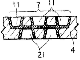
제1도는 다수의 떨어져 있는 분리 지역들 중 하나를 나타내는 본 발명에 따른 슬라이드 파스너 체인의 부분 평면도.1 is a partial plan view of a slide fastener chain according to the present invention showing one of a plurality of distant separation zones.
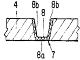
제2도는 제1도의 선 II-II에 따른 확대 단면도.2 is an enlarged sectional view taken along line II-II of FIG.
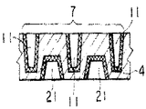
제3도는 개조된 분리지역을 나타내는, 제2도와 유사한 단면도.3 is a cross-sectional view similar to FIG. 2 showing a modified separation zone.
제4도는 제2예에 따른 슬라의드 파스너 체인의 평면도.4 is a plan view of the slad fastener chain according to the second example.
제5도는 제 3예를 나타내는, 제 1도와 유사한 평면도.FIG. 5 is a plan view similar to FIG. 1 showing a third example. FIG.
제6및 7도는 제5도의 각각 선 VI-VI 및 선 VII-VII에 따른 확대 단면도.6 and 7 are enlarged cross sectional views taken along lines VI-VI and VII-VII, respectively, in FIG. 5;
제8도는 제4예에 따른 슬라이드 파스너 체인의 평면도.8 is a plan view of a slide fastener chain according to a fourth example.
제9도는 제8도의 A부분을 나타내는 세부도.FIG. 9 is a detailed view showing part A of FIG.
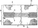
제10도는 제9도의 선 X-X에 따른 확대 단면도.10 is an enlarged sectional view taken along the line X-X of FIG.
제11도는 개조된 분리 지역을 나타내는, 제10도와 유사한 단면도.FIG. 11 is a sectional view similar to FIG. 10 showing a modified separation zone.
제12도는 제5예를 나타내는, 제8도와 유사한 도면.FIG. 12 is a view similar to FIG. 8 showing a fifth example. FIG.
제13및 14도는 제12도의 각각 선 XIII-XIII 및 선 XIV-XIV에 따른 확대 단면도.13 and 14 are enlarged sectional views taken along the lines XIII-XIII and XIV-XIV, respectively, of FIG.
제15도는 제 6예에 따른 슬라이드 파스너 체인의 평면도.15 is a plan view of a slide fastener chain according to a sixth example.
제16및 17도는 제15도의 각각 선 XVI-XVI 및 선 XVII-XVII에 따른 확대 단면도.16 and 17 are enlarged sectional views taken along lines XVI-XVI and XVII-XVII, respectively, in FIG.
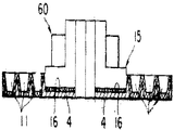
제18도는 제7예에 따른 슬라이드 파스너 체인의 평면도.18 is a plan view of the slide fastener chain according to the seventh example.
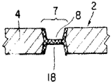
제19도는 제18도의 선 XIX-XIX에 따른 확대 단면도.19 is an enlarged sectional view taken along line XIX-XIX of FIG. 18;
제20도는 제 1도의 분리지역의 개조예를 나타내는 단면도.20 is a cross-sectional view showing an example of remodeling the separation zone of FIG.
제21및 22도는 제8도의 분리지역의 개조예들을 나타내는 단면도.21 and 22 are cross-sectional views showing modifications of the separation zone of FIG.
* 도면의 주요부분에 대한 부호의 설명* Explanation of symbols for main parts of the drawings
1 : 슬라이드 파스너 체인 2 : 파스너 스트링어1: slide fastener chain 2: fastener stringer
3 : 결합 엘레멘트 4 : 스트링어 테이트3: join element 4: stringer date
5 : 재봉선 6 : 결합엘레멘트없는 부분5: seam 6: part without joining element
7 : 분리지역 8 : 요홈부7: separation area 8: groove
8a, 8b : 요홈부의 벽 9 : 놋치8a, 8b: wall of grooves 9: notches
11 : 불연속 요홈부 15 : 스트립11: discontinuous groove 15: strip
본 발명은 슬라이드 파스너의 제조에 관한 것으로, 더 구체적으로는, 연속적인 길이의 슬라이드 파스너스트링어에 관한 것이다.The present invention relates to the manufacture of a slide fastener, and more particularly to a slide fastener stringer of continuous length.
슬라이드 파스너의 제조에 있어서, 슬라이드 파스너 체인을 가위 또는 펀치와 같은 특수한 절단 기구에 의해 적당한 길이의 슬라이드 파스너로 절단하는 것이 일반적이다. 본 발명은 절단기구를 사용하지 않고 오직 손으로 슬라이드 파스너를 분리, 즉 절단할 수 있는 개량된 슬라이드 파스너 체인을 제공한다.In the manufacture of a slide fastener, it is common to cut the slide fastener chain into a slide fastener of a suitable length by a special cutting mechanism such as scissors or a punch. The present invention provides an improved slide fastener chain capable of separating, ie cutting, the slide fastener by hand only without the use of a cutting tool.
본 발명이 따른 슬라이드 파스너 체인은, 1쌍의 연속적인 파스너 스트링어를 따라 소정의 간격으로 떨어져 있고 그 파스너 스트링어를 횡으로 가로질러 연장하여 있는 다수의 분리 지역들을 가지고 있다.The slide fastener chain according to the present invention has a plurality of separation zones spaced at predetermined intervals along a pair of consecutive fastener stringers and extending transversely across the fastener stringers.
각 분리지역은 소정의 분리지역에서 스트링어의 열가소성 합성 물질을 용융시킴에 의해 적어도 부분적으로 얇게되거나 또는 홈을 이루어 형성되어 있다.Each separation zone is formed at least partially thinned or grooved by melting the thermoplastic composite material of the stringer at a predetermined separation zone.
따라서, 본 발명의 목적은, 절단기구를 사용하지 않고 어려움없이 손으로 찢어 소정 길이의 슬라이드 파스너로 분리, 즉 절단될 수 있는 슬라이드 파스너 체인을 제공하는데 있다.Accordingly, it is an object of the present invention to provide a slide fastener chain which can be torn by hand without difficulty without the use of a cutting tool and separated, that is, cut into a slide fastener of a predetermined length.
본 발명의 다른 목적은, 손으로 찢는데 충분히 얇으나, 파스너 체인이 운송중 분리 지역에서 우연히 찢어지는 것을 방지하는데 충분히 두꺼운 다수의 얼어져 있는 분리 지역들을 가진 슬라이드 파스너 체인을 제공하는데 있다.It is a further object of the present invention to provide a slide fastener chain having a plurality of frozen separation zones which are thin enough to tear by hand but thick enough to prevent the fastener chain from accidentally tearing in the separation zone during transport.
본 발명의 많은 다른 잇점, 특징 및 목적들은, 본 발명의 원리를 구체화하는 여러가지 예들이 도시된 첨부 도면과 관련하여 기술된 그들 바람직한 실시예들의 하기 설명으로부터 명백하게 될 것이다.Many other advantages, features and objects of the present invention will become apparent from the following description of those preferred embodiments described in connection with the accompanying drawings, in which various examples embodying the principles of the invention are shown.
제1도에 도시된 바와 같이, 슬라이드 파스너 체인 1(이하, "파스너 체인"이라 약칭함)은, 1쌍의 스트링어 테이프 4,4들에 그들의 내측 종방향 연부를 따라 부착된 1쌍의 결합 엘레멘트열 3,3을 가지는 연속적인 길이의 1쌍의 파스너 스트링어 2,2를 포함한다.As shown in FIG. 1, the slide fastener chain 1 (hereinafter abbreviated as “fastener chain”) is a pair of couplings attached along their inner longitudinal edges to a pair of
각 테이프 4는 합성 섬유사, 또는 천연 섬유와 합성 섬유의 혼방사로 조직 또는 편조된 제직물 또는 편직물이다. 각 열의 결합 엘레멘트 3은 열가소성 합성 수지로 만들어진 코일형 또는 지그재그형의 필라멘트 형태이며, 재봉사 5에 의해 테이프 4에 부착되어 있다. 파스너 체인 1은 테이프의 내측 종방향 연부들을 따라 소정 거리로 떨어져 있는 다수의 결합 엘레멘트 없는 부분들 6(그 부분들중 하나만이 도시됨)을 가지고있다.Each
또한 파스너 체인 1은 다수의 분리 지역 7(그 지역들중 하나만이 도시됨)을 가지고 있고, 그 분리지역을 따라 파스너 체인 1이 각개 슬라이드 파스너로 분리, 즉 인열된다. 그 분리 지역 7은 파스너 체인 1을 따라 소정 간격으로 떨어져 있고, 각 분리지역 7은 결합 엘레멘트 없는 부분 6에서 파스너 체인 1을 가로질러 횡으로 연장하여 있다. 각 분리지역 7은 1쌍의 종방향으로 정립된 직선 요홈부 8,8로 이루어져 있고, 각 요홈부는 각개 파스너 스트링어 2의 일 표면에 배치되고 파스너 스트링어 2를 가로질러 횡으로 연장하여 있다. 그 요홈부 8,8은 사다리꼴 단면(제 2도)을 가지며, 그러한 요홈부들 각각은 그의 전체 길이에 걸쳐 균일한 두께를 가지고 있다.The
요홈부 8,8은 가열된 날(edge) 또는 로울러(도시안됨)에 의해, 또는 공지 구조의 초고주파 용융 장치(도시안됨)에 의해 소정의 분리지역 7에서 파스너 체인 1을 압착함에 의해 형성될 수 있다. 그리하어 그 소정의 분리지역 7의 열가소성 합성 섬유(테이프 4,4에 함유된)가 용융되어 요홈부 8,8의 벽 8a,8b릍 형성한다. 이런 용융의 결과로, 재봉사 5,5가 그 요홈부 8,8에서 절단된다. 각 요홈부 8의 저벽 8a는 테이프 4의 일반적인 두께보다 상당히 얇으나, 운송 중 슬라이드 파스너 체인 1이 그러한 요홈부에서 부주의하여 인열되거나 절단되는 것을 방지하는데 충분한 두께를 갖는다.
그렇게 하여 제공된 분리지역 7을 갖는 파스너 체인 1은 절단기구를 사용하지 않고 어려움없이 손으로 찢어 각개 슬라이드 파스너로 절단될 수 있다.The
각 요홈부 8의 저벽 8a는 분리, 즉 절단을 보조하도록, 요홈부 8의 모서리들을 따라 연장하는 1쌍의 놋치(notch) 9,9(제 3 도)를 가질 수 있다.The
제 4 도는 제2예에 따른 개조된 슬라이드 파스너 체인 10을 나타낸다. 그 파스너 체인 10은 제 1도의 파스너 체인 1과 유사하나, 각 분리지역 7의 요홈부 8,8이 지그재그로 연장하여 있다는 것만이 다르다.4 shows a modified
제5도는 제3예에 따른 개조된 슬라이드 파스너 체인 20을 나타내며, 그 파스너 체인 20은 제 1 도의 파스너 체인 1과 유사하나, 각 요홈부 8이 그 요홈부를 따라 교대로 두께가 다르게된 다수의 긴 부분 및 짧은부분 8a' 및 8a" 로 이루어져 있다는 점만이 다르다. 긴부분 8a'는 제6및 7도에 도시된 바와 같이 짧은 부분 8a"의 두께 보다 작은 두께를 갖는다.FIG. 5 shows a modified
제8도는 제4예에 따른 개조된 슬라이드 파스너 체인 30을 나타내며, 그 파스너 체인 30은, 각 분리지역 7이 파스너 체인 30의 일 표면에 횡으로 가로질러 배치된 3열의 불연속적인 요홈부 11, 11, 11로 이루어진 점에서만 제1, 4및 5도의 것들과 다르다. 각 열의 요홈부 11은 인접 열의 요홈부에 측방으로 정렬되어 있고 그 인접열의 요홈부의 각 단부를 지나 연장하여 부분적으로 중첩하여 있다. 그리하여, 테이프 4의 경사 4a가 적어도 하나의 요홈부 11에 의해 차단되어 파스너 체인 30이 어려움 없이 분리지역 7을 따라 분리, 즉 인열될 수 있다.FIG. 8 shows a modified
인접열들 사이의 요홈부 11,11은 테이프 4의 일반적인 두께와 동일한 두께를 가진다(제10도). 또 다르게는, 그러한 일련의 요홈 부들이 테이프 4의 두께 보다 작고 요홈부 11a의 두께보다 큰 두께를 가질수도 있고 (제11도), 그리하여 분리지역 7에서 파스너체인 30의 분리를 용이하게 한다.The recesses 11 and 11 between adjacent rows have the same thickness as the general thickness of the tape 4 (Fig. 10). Alternatively, such a series of grooves may have a thickness smaller than the thickness of the
제12도는 제 5예에 따른 슬라이드 파스너 체인 40을 나타내며, 그 파스너 체인 40은, 분리 지역 7이 파스너 체인 40의 일표면에 횡으로 가로 질러 배치된 2열의 불연속적인 요홈부 13,13으로 이루어진 점만이 제8도의 파스너 체인 30과 다르다. 각 열의 요홈부 13은 각기 다른 두께의 다수의 길고 짧은 요홈부 13',13"가 교대로 배치되어 이루어져 있고, 일 열의 긴 요홈부 13'는 따른 열의 긴 요홈부와 측방으로 일치되어 있고 그 다른 열의 긴 요홈부의 각 단부를 지나 연장하여 부분적으로 중첩되어 있다. 각 짧은 요홈부 13"의 저벽 13"a는 제13및 14도에 도시된 바와 같이 각 긴 요홈부 13'의 저벽 13'a보다 두껍다.FIG. 12 shows the
제15도는 제 6예에 따른 슬라이드 파스너 체인 50을 나타내며, 그 파스너 체인 50은, 결합 엘레멘트 없는 부분들이 존재하지 않고 각 직선의 요홈부 14가 테이프 4와 결합 엘레멘트 열 3을 가로질러 횡으로 연장하여 있는 점에서 제1도의 파스너 체인 1과 다르다. 그 요홈부 14는 가열 날 또는 로울러(도시안됨)에 의해 또는 초고주파 용융 장치(도시안됨)에 의해 소정의 분리지역 7에서 파스너 체인 50을 압착함에 의해 형성될수 있고, 그리하여, 소정의 분리지역 7의 결합 엘레멘트 3의 열 가소성 합성 수지가 녹아서, 제16및 17도에 도시된 바와 같이 요홈부 14의 벽 14a, 14b를 형성한다.FIG. 15 shows the
제18도는 제7예에 따른 슬라이드 파스너 체인 60을 나타낸다. 그 파스너 체인 60은 다수의 열 가소성 합성수지 스트립 15(그 스트립들중 하나만 도시됨)가 결합 엘레멘트 없는 부분 6(제8도)에 부착된 것이 제 8도의 파스너 체인 30과 다르다. 그 스트립 15는 재봉사 5,5가 결합 엘레멘트 없는 부분 6에서 마모되는 것을 방지하도록 작용하다. 3열의 불연속적인 요홈부 11,11,11이 그 스트립 15에 의해 차단되어 있고, 그 스트립 15의 일련의 연속적인 요홈부 16가 3열의 불연속적인 요홈부 11들중 한 열과 종방향으로 일치되어 있다. 그리하여, 그 요홈부 11, 테이프 4,4의 용융된 열가소성 합성섬유들에 의해 형성되고, 요홈부 16은 스트립 15의 용융된 열가소성 합성 수지에 의해 형성된다.18 shows a
제20도는, 또 다른 쌍의 종방향 요홈부 18,18이 각 스트링어 2,2의 타측 표면에 배치되고 스트링어 2,2의 일 표면의 요홈부 8,8과 일치되어 있는, 제1도의 분리지역 7의 개조예를 나타낸다.20 shows another pair of longitudinal grooves 18, 18 arranged on the other surface of each
제21및 22도는 또 다른 2열의 불연속적인 요홈부 21,21이 스트링어 2,2의 타측 표면에 그 스트링어의 일표면상의 3열의 요홈부 11,11,11에 대해 엇갈리게 배치된, 제8도의 분리지역 7의 또 다른 개조예들을 나타낸다.Figures 21 and 22 show that another two rows of
전술한 실시예들중 어느 한 예에서, 테이프의 경사가 요홈부들중 적어도 하나에 의해 차단되어 파스너 체인이 어려움없이 손으로 분리지역 7을 따라 분리, 즉 인열될 수 있다.In any of the foregoing embodiments, the inclination of the tape can be blocked by at least one of the recesses so that the fastener chain can be separated, i.e., teared along the
약간의 경사들이 차단되지 않거나 완전히 녹지 않고 잔류하는 경우, 용이하고 적절한 분리가 달성될 수 없다. 또한, 그러한 완전히 녹지 않은 경사들 때문에, 분리, 즉 인열된 테이프 단부들이 추하게 될 수 있다.If some slopes remain unblocked or do not melt completely, easy and proper separation cannot be achieved. Also, due to such completely unmelted warps, separate, ie, teared tape ends may be ugly.
각종 실시예들이 설명되었으나 본 발명의 청구범위 내에서 많은 미세한 개조가 당업자에 의해 제기될 수 있다.While various embodiments have been described, many minor modifications may be made by those skilled in the art within the scope of the claims.
Claims (15)
Applications Claiming Priority (2)
| Application Number | Priority Date | Filing Date | Title |
|---|---|---|---|
| JP56160135A JPS5861702A (en) | 1981-10-09 | 1981-10-09 | Separation part of slide fastener continuous chain |
| JP160135 | 1981-10-09 |
Publications (2)
| Publication Number | Publication Date |
|---|---|
| KR840001821A KR840001821A (en) | 1984-06-07 |
| KR840002097B1 true KR840002097B1 (en) | 1984-11-15 |
Family
ID=15708624
Family Applications (1)
| Application Number | Title | Priority Date | Filing Date |
|---|---|---|---|
| KR8204549A KR840002097B1 (en) | 1981-10-09 | 1982-10-08 | Slide fastener chain |
Country Status (12)
| Country | Link |
|---|---|
| US (1) | US4528731A (en) |
| EP (1) | EP0077035B1 (en) |
| JP (1) | JPS5861702A (en) |
| KR (1) | KR840002097B1 (en) |
| AU (1) | AU537174B2 (en) |
| BR (1) | BR8205993A (en) |
| CA (1) | CA1220329A (en) |
| DE (2) | DE77035T1 (en) |
| ES (3) | ES267698Y (en) |
| GB (1) | GB2107389B (en) |
| HK (1) | HK68188A (en) |
| MY (1) | MY8700436A (en) |
Families Citing this family (1)
| Publication number | Priority date | Publication date | Assignee | Title |
|---|---|---|---|---|
| EP0894948B1 (en) * | 1997-07-28 | 2003-01-15 | ALSTOM (Switzerland) Ltd | Combined gas-steam power plant with once-through steam generator |
Family Cites Families (14)
| Publication number | Priority date | Publication date | Assignee | Title |
|---|---|---|---|---|
| US2292322A (en) * | 1940-03-02 | 1942-08-04 | Century Ribbon Mills Inc | Fabric |
| US3081462A (en) * | 1960-06-30 | 1963-03-19 | New York Notion Co Inc | Slide fastener tapes and the method of making same |
| US3322325A (en) * | 1962-01-30 | 1967-05-30 | Roy L Bush | Bag seal utilizing pressure sensitive tape having weakened transverse zones |
| FR2019731A5 (en) * | 1969-01-08 | 1970-07-03 | Licences Brevets Ste F F | |
| DE1911501A1 (en) * | 1969-03-06 | 1971-01-14 | Opti Holding Ag | Coherent band made of individual zippers |
| JPS5245362Y2 (en) * | 1971-04-05 | 1977-10-15 | ||
| FR2219829A1 (en) * | 1973-03-01 | 1974-09-27 | Dollfus Mieg Et Cie | Tool for applying sliding clasp fastenered - by simultaneous perforation and welding to provide stopped ends |
| JPS5911624Y2 (en) * | 1974-02-07 | 1984-04-10 | ワイケイケイ株式会社 | Slide fastener |
| DE2537575C3 (en) * | 1975-08-22 | 1980-01-24 | Yoshida Kogyo K.K., Tokio | Device for the protected storage and dispensing of zippers |
| US4187591A (en) * | 1976-07-12 | 1980-02-12 | Yoshida Kogyo K K | Continuous slide fastener stringers |
| JPS5637609Y2 (en) * | 1976-07-12 | 1981-09-03 | ||
| US4123827A (en) * | 1977-07-27 | 1978-11-07 | Yoshida Kogyo K.K. | Slide fastener chain |
| JPS5550304A (en) * | 1978-10-11 | 1980-04-12 | Yoshida Kogyo Kk | Fastener chain and production |
| JPS5568306A (en) * | 1978-11-16 | 1980-05-23 | Yoshida Kogyo Kk | Method and apparatus for preventing fray of slide fastener |
-
1981
- 1981-10-09 JP JP56160135A patent/JPS5861702A/en active Granted
-
1982
- 1982-09-30 GB GB08227882A patent/GB2107389B/en not_active Expired
- 1982-09-30 US US06/430,827 patent/US4528731A/en not_active Expired - Fee Related
- 1982-09-30 AU AU88923/82A patent/AU537174B2/en not_active Ceased
- 1982-10-07 DE DE198282109301T patent/DE77035T1/en active Pending
- 1982-10-07 EP EP82109301A patent/EP0077035B1/en not_active Expired
- 1982-10-07 CA CA000412999A patent/CA1220329A/en not_active Expired
- 1982-10-07 DE DE8282109301T patent/DE3276612D1/en not_active Expired
- 1982-10-08 ES ES1982267698U patent/ES267698Y/en not_active Expired
- 1982-10-08 ES ES1982267697U patent/ES267697Y/en not_active Expired
- 1982-10-08 KR KR8204549A patent/KR840002097B1/en active
- 1982-10-08 BR BR8205993A patent/BR8205993A/en unknown
- 1982-10-08 ES ES1982267696U patent/ES267696Y/en not_active Expired
-
1987
- 1987-12-30 MY MY436/87A patent/MY8700436A/en unknown
-
1988
- 1988-09-01 HK HK681/88A patent/HK68188A/en unknown
Also Published As
| Publication number | Publication date |
|---|---|
| DE77035T1 (en) | 1983-09-15 |
| ES267696Y (en) | 1983-11-16 |
| JPS5861702A (en) | 1983-04-12 |
| ES267698Y (en) | 1983-10-16 |
| BR8205993A (en) | 1983-09-13 |
| US4528731A (en) | 1985-07-16 |
| ES267696U (en) | 1983-05-01 |
| AU537174B2 (en) | 1984-06-14 |
| GB2107389B (en) | 1985-06-19 |
| EP0077035B1 (en) | 1987-06-24 |
| EP0077035A3 (en) | 1984-11-28 |
| ES267697Y (en) | 1983-10-16 |
| KR840001821A (en) | 1984-06-07 |
| JPS636204B2 (en) | 1988-02-08 |
| ES267697U (en) | 1983-04-01 |
| HK68188A (en) | 1988-09-09 |
| DE3276612D1 (en) | 1987-07-30 |
| EP0077035A2 (en) | 1983-04-20 |
| GB2107389A (en) | 1983-04-27 |
| ES267698U (en) | 1983-04-01 |
| AU8892382A (en) | 1983-05-26 |
| CA1220329A (en) | 1987-04-14 |
| MY8700436A (en) | 1987-12-31 |
Similar Documents
| Publication | Publication Date | Title |
|---|---|---|
| US4752992A (en) | Slide fastener with thermoplastic end stops | |
| KR870000888A (en) | Sheet material for fasteners and forming method thereof | |
| KR840007071A (en) | Waterproof slide fastener stringer and manufacturing method thereof | |
| KR940006313B1 (en) | Separable fastener strip | |
| EP2510146B1 (en) | Hinge type seaming element for joining ends of an industrial textile | |
| US3414948A (en) | Thermoplastic strips for sliding clasp fasteners | |
| US3849843A (en) | Slide fastener | |
| CN103068272A (en) | Slide fastener and method for manufacturing same | |
| US2814847A (en) | Reinforced slide fasteners | |
| KR860001940B1 (en) | A method of producing an airtight and waterproof slide fastener | |
| KR840002097B1 (en) | Slide fastener chain | |
| BR0202216A (en) | Interlaced sliding clasp | |
| CA1255107A (en) | Abrasive belt with a joint extending transversely to its longitudinal direction | |
| US3895418A (en) | End stop member for sliding clasp fasteners | |
| US3482292A (en) | Endstop members for slide fasteners | |
| KR850003132Y1 (en) | Slide fastener | |
| KR860002378Y1 (en) | Slide fastener | |
| US4187591A (en) | Continuous slide fastener stringers | |
| US3971868A (en) | Fabric tape for slide fastener stringers with means to prevent unraveling at its severed ends | |
| GB1450162A (en) | Sliding clasp fasteners and method of making the same | |
| US3903572A (en) | Slide fastener | |
| KR880000929Y1 (en) | Slide fastener stringer | |
| JPS58121903A (en) | Separation part of continuous slide fastener chain | |
| JPS636203B2 (en) | ||
| KR830001787Y1 (en) | Slide fasteners with creeper openings |