KR840000998B1 - Apparatus for correcting for temperature-induced tracking errors in a system for recovering information from a recording disc - Google Patents
Apparatus for correcting for temperature-induced tracking errors in a system for recovering information from a recording disc Download PDFInfo
- Publication number
- KR840000998B1 KR840000998B1 KR1019800001421A KR800001421A KR840000998B1 KR 840000998 B1 KR840000998 B1 KR 840000998B1 KR 1019800001421 A KR1019800001421 A KR 1019800001421A KR 800001421 A KR800001421 A KR 800001421A KR 840000998 B1 KR840000998 B1 KR 840000998B1
- Authority
- KR
- South Korea
- Prior art keywords
- signal
- information
- disc
- track
- information track
- Prior art date
Links
- 238000000034 method Methods 0.000 claims description 9
- 238000001514 detection method Methods 0.000 claims description 6
- 230000000737 periodic effect Effects 0.000 claims description 3
- 238000001914 filtration Methods 0.000 claims description 2
- 230000003287 optical effect Effects 0.000 claims 1
- 230000005855 radiation Effects 0.000 abstract description 17
- 230000008602 contraction Effects 0.000 abstract description 6
- 239000004020 conductor Substances 0.000 description 8
- 230000000694 effects Effects 0.000 description 3
- 239000000463 material Substances 0.000 description 2
- 230000015572 biosynthetic process Effects 0.000 description 1
- 230000001934 delay Effects 0.000 description 1
- 238000010586 diagram Methods 0.000 description 1
- 230000008020 evaporation Effects 0.000 description 1
- 238000001704 evaporation Methods 0.000 description 1
- DIRFUJHNVNOBMY-UHFFFAOYSA-N fenobucarb Chemical compound CCC(C)C1=CC=CC=C1OC(=O)NC DIRFUJHNVNOBMY-UHFFFAOYSA-N 0.000 description 1
- 230000008018 melting Effects 0.000 description 1
- 238000002844 melting Methods 0.000 description 1
- 238000012986 modification Methods 0.000 description 1
- 230000004048 modification Effects 0.000 description 1
- 230000010355 oscillation Effects 0.000 description 1
- 230000000704 physical effect Effects 0.000 description 1
- 238000004804 winding Methods 0.000 description 1
Images


Classifications
-
- G—PHYSICS
- G11—INFORMATION STORAGE
- G11B—INFORMATION STORAGE BASED ON RELATIVE MOVEMENT BETWEEN RECORD CARRIER AND TRANSDUCER
- G11B7/00—Recording or reproducing by optical means, e.g. recording using a thermal beam of optical radiation by modifying optical properties or the physical structure, reproducing using an optical beam at lower power by sensing optical properties; Record carriers therefor
- G11B7/08—Disposition or mounting of heads or light sources relatively to record carriers
- G11B7/09—Disposition or mounting of heads or light sources relatively to record carriers with provision for moving the light beam or focus plane for the purpose of maintaining alignment of the light beam relative to the record carrier during transducing operation, e.g. to compensate for surface irregularities of the latter or for track following
- G11B7/0901—Disposition or mounting of heads or light sources relatively to record carriers with provision for moving the light beam or focus plane for the purpose of maintaining alignment of the light beam relative to the record carrier during transducing operation, e.g. to compensate for surface irregularities of the latter or for track following for track following only
- G11B7/0904—Dithered tracking systems
-
- G—PHYSICS
- G11—INFORMATION STORAGE
- G11B—INFORMATION STORAGE BASED ON RELATIVE MOVEMENT BETWEEN RECORD CARRIER AND TRANSDUCER
- G11B21/00—Head arrangements not specific to the method of recording or reproducing
- G11B21/02—Driving or moving of heads
- G11B21/10—Track finding or aligning by moving the head ; Provisions for maintaining alignment of the head relative to the track during transducing operation, i.e. track following
- G11B21/106—Track finding or aligning by moving the head ; Provisions for maintaining alignment of the head relative to the track during transducing operation, i.e. track following on disks
Abstract
Description
제1도는 판독비임을 기록디스크상의 정보트랙의 중앙선에 일치시키기 위한 본 발명의트랙킹(traacking) 장치의 개략적인 블록 다이어그램.1 is a schematic block diagram of a tracking device of the present invention for matching the read beam to the center line of an information track on a recording disc.
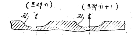
제2a도는 디스크의 중심에서 반경방향으로 취한, 제1도의 기록디스크 표면의 부분 단면도.FIG. 2A is a partial cross-sectional view of the recording disk surface of FIG. 1 taken radially from the center of the disk. FIG.
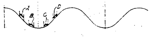
제2b도는 제2a도의 디스크에 의해 반사된 반사비임의 평균 강도를 디스크 반경의 함수로 나타낸 그래프.FIG. 2B is a graph showing the average intensity of the reflection beam reflected by the disk of FIG. 2A as a function of disk radius.
제3도는 제1도의 트랙킹장치에서 사용되는 일정 주파수, 일정진폭의 반경방향 진동신호를 나타내는 그래프.3 is a graph showing a radial vibration signal of a constant frequency and a constant amplitude used in the tracking device of FIG.
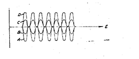
제4도는 반경방향 진동신호의 효과를 나타내는, 정보트랙의 중앙선에 대한 판독비임의 4개의 다른 위치에서의 반사비임 강도신호들을 나타내는 그래프.4 is a graph showing the reflection beam intensity signals at four different positions of the reading beam relative to the center line of the information track, showing the effect of the radial vibration signal.
제5도는 제3도의 반경방향 진동신호와 제4도의 4개의 강도신호들을 곱해서 얻은 중간신호들을 나타내는 그래프.5 is a graph showing intermediate signals obtained by multiplying the radial vibration signal of FIG. 3 by the four intensity signals of FIG.
본 발명은 정보기록매체상에 정보를 기록하고 판독하기 위한 장치에 관한 것으로서, 더욱 구체적으로는 방사비임을 이와 같은 정보기록매체상의 정보기록트랙(trac k)에 일치시키기 위한 장치에 관한 것이다.The present invention relates to an apparatus for recording and reading information on an information recording medium, and more particularly to an apparatus for matching a radiation ratio to an information recording track (trac k) on such an information recording medium.
이러한 형태의 장치는, 기록용 방사비임(이하, 기록비임이라고 함)과 판독용 방사비임(이하, 판독비임이라고 함)을 모두 이용하여 디스크를 주사(走査)하는, 기록후에 직접 판독하는 방식(directread-afterwrite)의 기록디스크 시스템에 특히 유용하다. 기록비임은 기록될 정보신호에 의해 강도가 변조되며, 따라서 디스크가 기록비임에 대해 상대적으로 회전함에 따라 원형의 정보트랙내에는 그 정보신호를 나타내는 극히 작은 연속적인 구멍(pit)들이 형성된다. 통상적으로, 각 정보트랙에서의 기록이 완료되면, 반경방향으로 이동가능한 캐리지(carriage)에 의해 기록비임의 반경방향 위치가 증가됨으로써 동심원으로 배열된 연속적인 정보트랙이 형성된다. 판독비임은 연속적인 구멍들이 형성된 직후에 그 구멍들을 주사하며, 따라서 기록된 정보에 의해 변조되어 반사된 방사비임(이하, 반사비임이라고 함)이 발생되게 한다. 이 반사비임은 정보신호가 올바르게 기록되었는가를 확인하는데 사용될 수 있다.A device of this type is a method of directly reading after recording, in which a disk is scanned using both a recording radiation beam (hereinafter referred to as a recording beam) and a reading radiation beam (hereinafter referred to as a read beam) ( This is particularly useful for recording disc systems with directread-afterwrite. The recording beam is modulated in intensity by the information signal to be recorded, so that as the disk rotates relatively to the recording beam, extremely small continuous pit representing the information signal is formed in the circular information track. Typically, when recording on each information track is completed, the radial position of the recording beam is increased by a radially movable carriage to form a continuous information track arranged concentrically. The read beam scans the holes immediately after successive holes are formed, thus causing a reflected radiation beam (hereinafter referred to as a reflection beam) to be modulated by the recorded information. This reflection beam can be used to confirm that the information signal is recorded correctly.
디스크상에 연속적으로 정보트랙을 형성할 때에는, 다음번 정보트랙으로 옮겨가기 전에 소정의 시간을 기다리는 것이 바람직하다. 기록비임은 이 시간동안 동작정지 (disable)의 상태에 있게 되는데, 장치의 주위온도가 변함에 따라 디스크가 팽창 또는 수축될 수 있으므로, 기록비임이 다시 동작하기 시작할 때에는 기록비임의 위치가 직전에 형성된 정보트랙의 위치에 대해 상대적으로 달라지게 된다. 이러한 상황은 매우 얇은 플라스틱제 기록디스크를 사용할 경우에 흔히 발생한다. 다음번 정보트랙이 디스크상의 적당한 반경방향 위치에 형성되도록 캐리지를 반경방향으로 적절히 이동시키는데 필요한 시간을 최소한으로 감소시키기 위해서는, 주위 온도의 변화에 관계없이 디스크상의 정보트랙들에 대해 캐리지가 소정의 관계를 계속 유지하도록 하는 것이 바람직하다.When continuously forming information tracks on the disc, it is desirable to wait for a predetermined time before moving to the next information track. The recording beam will be in a disabled state during this time, since the disk may expand or contract as the ambient temperature of the device changes, so that the position of the recording beam is formed immediately before the recording beam starts to operate again. It will be relative to the position of the information track. This situation often occurs when using a very thin plastic recording disc. In order to minimize the time required to properly move the carriage in the radial direction so that the next information track is formed at the appropriate radial position on the disc, the carriage has a predetermined relationship to the information tracks on the disc regardless of the change in ambient temperature. It is desirable to keep it.
이것을 달성하기 위한 한가지 방법으로는, 디스크의 온도를 계속적으로 측정한 다음, 기록될 다음번 정보트랙의 실제 반경을 추산하고, 그 추산된 반경에 대한 적절한 위치에 캐리지를 유지시키는 방법이 있다. 그러나, 온도는 장치 전체에 걸쳐 그리고 디스크 전체에 걸쳐 균일하지 않은 것이 보통이기 때문에, 이방법은 전적으로 만족할만한 것은 아니다. 즉, 이 방법으로는 높은 정보기록밀도가 가능하도록 충분히 정밀하게 위치시킬 수 없다.One way to accomplish this is by continuously measuring the temperature of the disc, then estimating the actual radius of the next information track to be recorded and keeping the carriage in the proper position for that estimated radius. However, this method is not entirely satisfactory since the temperature is usually not uniform throughout the device and throughout the disk. In other words, this method cannot be positioned precisely enough to enable a high information recording density.
기록디스크상의 정보트랙의 반경방향 온도변화에 의한 이와 같은 변동을 보상하기 위한 또 다른 방법으로는, 반경방향으로 이동가능한 캐리지를 디스크의 물리적 성질과 거의 같은 성질을 갖는 특수한 장착대(mounting)에 설치하는 방법이 있다. 이 경우, 디스크와 캐리지 장착대는 주위 온도의 변화에 대응하는 양만큼의 영향을 받게 되므로, 캐리지는 디스크상의 정보트랙들에 대해자동적으로 소정의 관계를 유지하게 된다. 그러나, 일반적으로는 주위온도의 변화에 의해 캐리지 장착대와 디스크가 동일한 영향을 받는다는 사실을 보장할 수 없기 때문에, 이 방법도 역시 전적으로 만족할만한 것이 못된다. 결과적으로, 종래에 얻을수 있었던 정보기록밀도에는 한계가 있었던 것이다.Another way to compensate for this variation due to the radial temperature change of the information track on the recording disc is to install a carriage which is radially movable in a special mounting which has almost the same properties as the physical properties of the disc. There is a way. In this case, the disc and the carriage mount are affected by an amount corresponding to the change in the ambient temperature, so that the carriage automatically maintains a predetermined relationship with respect to the information tracks on the disc. However, this method is also not entirely satisfactory, since in general it is not possible to guarantee that the carriage mount and the disk are equally affected by changes in ambient temperature. As a result, there was a limit to the information recording density conventionally obtained.
따라서, 온도변화에 의해 디스크가 캐리지에 대해 팽창 혹은 수축될지라도, 반경방향으로 이동가능한 캐리지를 디스크상의 정보트랙에 대해 소정의 관계로 유지시킬 수 있는 효과적인 장치를 개발한 필요성이 존재하여 왔다. 본 발명은 이와같은 필요성을 충족시키는 것이다.Therefore, there has been a need to develop an effective device capable of maintaining a radially movable carriage in a predetermined relation to an information track on the disk, even if the disk expands or contracts with respect to the carriage due to temperature changes. The present invention satisfies this need.
기본적으로, 본 발명은 예컨대 방사비임과 같은 주사수단을 기록매체상의 정보트랙에 대한 소정의 위치에 유지시키기 위한 트랙킹(tracking) 장치에 관한 것이다. 본 발명의 장치는, 정보트랙의 축에 대해횡방향으로 이동가능하며 방사비임을 기록매체에 투사시키기 위한 캐리지수단과, 정보트랙에 대한 방사비임의 입사 위치를 검지하기 위한 수단을 포함하고 있다. 본 발명에 의하면 상기 검지수단은 방사비임의 검지된 위치에 따라 제어펄스신호를 발생시키며, 또한 본 발명의 장치에는 상기 제어펄스신호에 반응하여 캐리지를 횡방향으로 이동시킴으로써 방사비임을 정보트랙에 대해[소정의 관계로 유지시키기 위한 스텝핑모우터(stepping motor) 수단이 더욱 포함되어 있다.Basically, the present invention relates to a tracking apparatus for holding a scanning means such as, for example, a radiation beam at a predetermined position with respect to an information track on a recording medium. The apparatus of the present invention comprises a carriage means for projecting a radiation beam onto a recording medium which is movable transverse to the axis of the information track, and means for detecting the position of incidence of the radiation beam on the information track. According to the present invention, the detecting means generates a control pulse signal in accordance with the detected position of the radiation beam, and the apparatus of the present invention moves the carriage in the transverse direction in response to the control pulse signal to the radiation beam. [Stepping motor means for maintaining in a predetermined relationship is further included.
특히, 본 발명의 트랙킹장치는, 가동(可動) 캐리지수단상에 장착된 대물렌즈를 거쳐 기록비임과 판독비임을 회전하고 있는 정보기록 디스크상에 접속시키는, 기록후에 직접 판독하는 방식의 기록시스템에서 사용되기에 적합하다. 이 시스템은 디스크상에 동심원 형태의 연속적인 원형 정보트랙들을 형성시키도록 작동한다. 또한, 어떤 정보트랙을 형성한 후에 다음번 정보트랙을 형성하기 위해 기다리는 동안, 기록비임은 동작정지의 상태로 되지만 판독비임은 계속적으로 디스크에 주사된다. 이때, 본 발명의 트랙킹장치는 최종 기록된 트랙에 판독비임이 일치되도록 판독비임을 유지시키므로, 캐리지에 대한 디스크의 팽창 또는 수축을 유발시키는 온도변화를 자동적으로 교정한다. 다음번 정보트랙을 디스크상에 형성시킬 때가 되면, 기록비임을 다시 입사시키기 전에 캐리지 수단을 반경방향으로 단지 1개트랙의 간격만큼 증가시킬 필요가 있다.In particular, the tracking device of the present invention is a recording system in which a direct reading method is performed after recording, by connecting a recording beam and a reading beam onto a rotating information recording disk via an objective lens mounted on the movable carriage means. Suitable for use The system operates to form contiguous circular information tracks on a disc. In addition, while waiting to form the next information track after the formation of a certain information track, the recording beam is brought into a stopped state while the read beam is continuously scanned onto the disc. At this time, the tracking device of the present invention maintains the read beam so that the read beam coincides with the last recorded track, thereby automatically correcting the temperature change causing the expansion or contraction of the disc relative to the carriage. When it is time to form the information track on the disc next time, it is necessary to increase the carriage means radially by only one track before entering the recording beam again.
스텝핑모우터수단은 온도변화에 기인한 디스크의 팽창 또는 수축에 부합되도록 캐리지수단을 반경방향 외측 혹은 내측으로 이동시킨다. 각 트랙의 간격은 스텝핑모우터수단내의 다수의 스텝들에 대응하는 것이 바람직한데, 이에 의해 본 발명의 장치는 판독비임을 바로 직전에 형성된 트랙의 중앙선에 매우 근접하게 정렬시켜 유지시키는데 충분한 해상도(resolution)를 가지게 된다.The stepping motor means moves the carriage means radially outward or inward to conform to the expansion or contraction of the disk due to temperature changes. The spacing of each track preferably corresponds to a number of steps in the stepping motor means, whereby the device of the present invention has a resolution sufficient to keep the readout ratio aligned very close to the centerline of the track just formed. Have).
검지수단에는 진동 트랙킹장치가 포함될 수 있는데, 이 진동트랙킹장치에서는 주사되는 정로트랙의 축에 수직인 방향으로 판독비임을발진(oscillate)시키기 위한 진동신호(dithersignal) 및 이에 관련된 반사경을 이용하고 있다. 이러한 발진에 의하면, 반사비임의 평균 방사강도를 대응하게 변화시키게 된다. 진동신호의 위상각(phase angle)에 대한 이와같은 방사강도 변화의 위상각 및 방사강도 변화의 진폭은, 주사되고 있는 트랙의 중앙선으로 부터의 판독비임의 편차의 방향 및 크기를 나타낸다.The detection means may include a vibration tracking device, which uses a vibration signal and a reflector associated therewith for oscillating the reading beam in a direction perpendicular to the axis of the forward track to be scanned. This oscillation causes the average radiation intensity of the reflection beam to change correspondingly. The phase angle of such a change in radiation intensity and the amplitude of the change in the radiation intensity with respect to the phase angle of the vibration signal indicate the direction and magnitude of the deviation of the read beam from the center line of the track being scanned.
본 발명의 다른 특징에 의하면, 검지된 한독비임의 트랙중앙선으로 부터의 편차가 소정의 값을 초과할때마다, 전진스텝 또는 후진스텝 펄스신호가 스텝핑모우터수단에 인가되어 캐리지를 반경방향외측 혹은 내측으로 이동시키며, 따라서 상기 편차를 교정하게 된다. 또한, 진동 트랙킹장치에는, 특히 디스크물질의 온도변화에 의해 야기되는 것과 같이 반사비임의 평균 방사강도에 있어서의 매우 낮은 주파수 변화만을 교정하기 위한 저역필터(low pass filter)가 포함될 수 있다.According to another feature of the invention, whenever a deviation from the track centerline of the detected German beam exceeds a predetermined value, a forward step or reverse step pulse signal is applied to the stepping motor means to radially outward or Moving inward, thus correcting the deviation. In addition, the vibration tracking device may include a low pass filter for correcting only very low frequency changes in the average radiation intensity of the reflecting beam, in particular caused by a change in temperature of the disk material.
본 발명의 기타의 목적 및 잇점들은, 본 발명의 바람직한 실시예가 도시되어 있는 첨부도면을 참조한 다음의 설명으로부터 더욱 명백하게 될 것이다.Other objects and advantages of the invention will become more apparent from the following description with reference to the accompanying drawings, in which preferred embodiments of the invention are shown.
제1도에는, 회전하고 있는 디스크(11)상의 정보기록트랙의 중앙선에 방사비임을 일치시키기 위한 트랙킹 서어보(servo)장치가 도시되어 있다. 이 장치는, 디스크상에 동심원으로 배열된 다수의 원형정보트랙에 정보를 기록하는데에 기록비임(13)을 이용하고, 기록된 직후 그 정보를 판독하는데에 판독비임(15)을 이용하는, 기록후에 직접 판독하는 방식의 장치에 사용된 예가 도시되어 있다.1 shows a tracking servo apparatus for matching the radiation beam to the center line of the information recording track on the rotating disk 11. The apparatus uses a
기록비임(13)은 기록레이저(17)에 의해 발생되어 변조기(19)로 전달된다. 이 변조기(19)는 도선(21)을 통해 공급되는 정보신호에 따라 기록비임의 강도를 변조시킨다. 이와같이 변조된 기록비임은 제1비임분할기(beam splitter)(23)를 통과해서 반사경(25)에 의해 반사된 다음, 대물렌즈(27)에 의해 디스크(11)상에 집속(focus)된다. 디스크(11)는 스핀들모우터(29)에 의해 소정의 각속도로 회전되며, 변조된 기록비임의 강도는 디스크물질의 용융 또는 증발이 일어날 수 있는 한계치 이상의 값 및 이하의 값을 교대로 갖게 되므로, 정보신호를 나타내는 연속적인 구멍(31) (제2도)들이 디스크상에 상호 간격을 두고 형성된다. 반사경(25)과 대물렌즈(27)는 모두 캐리지(23)상에 장착되어 있으며, 이 캐리지는 각 정보트랙에서의 기록이 완료된 후에 대략 2미크론씩 반경방향으로 이동함으로써, 밀접한 간격의 동심원으로 배치된 연속적인 정보트랙들을 형성시킨다.The
판독비임(15)은 판독레이저(35)에 의해 거의 균일한 강도로 발생된다. 이 판독비임(15)은 제2 비임분할기(37)를 통과한 후에 바이모르프(bimorph) 반사경 등과 같은 광학적 가동부적(39)에 의해 제1 비임분할기(23)로 반사되며, 그후 상기와 같이 강도변조된 기록비임(13)과 결합된다. 다음, 이 판독비임(15)은 캐리지(33)에 장착된 반사경(25)과 대물렌즈(27)에 의해 디스크(11)로 투사된다. 이 판독비임과 기록비임은, 디스크의 공통 반경상에서 기록비임이 약 50미크론만큼 판독비임보다 앞서 임사되도록 조정되어 있다.The
기록비임(13)에 의해 형성된 정보를 함유하고 있는 구멍(31)은 균일한 강도의 판독비임(15)을 반사시키지 않는 반면, 이러한 구멍이 형성되어 있지 않은 디스크상의 나머지 부분들은 판독비임을 매우 잘반사시킨다. 이와같이 하여, 기록된 정보에 의해 강도변조된 반사비임(41)이 발생된다. 이반사비임(91)은 대물렌즈(27)에 의해 수집되어 판독비임과 동일한 경로를 따라 제2비임분할기(37)로 전달되고, 이로 부터 반사되어 광검지기(photodetector)(43)로 전달된다. 이 광검지기(43)는 반사비임의 강도에 비례하는 전기신호를 발생시킨다. 기록후에 직접 판독하는 방식의 장치에 있어서의 데이타부시스템(subsystem) (도시하지 않았음)은 이러한 전기적 강도신호를 도선(21)을 통해 기록비임 변조기(19)에 이미 공급되었던 정보신호를 지연시킨 기록정보와 비교함으로써, 그 정보가 디스크(11)상에 적절히 기록되었는가를 확인하다.The
하나의 정보트랙이 디스크(11)상에 형성된 후에 다음번 정보트랙에 기록될 정보신호가 수신되기 전에는, 시간적인 지연이 있게 된다. 이 동안에는 기록비임(13)이 동작정지의 상태에 있게 되므로, 디스크상에는 구멍이 형성되지 않는다. 그러나, 반경방향으로 이동가능한 캐리지(33)를 디스크상의 정보트랙들에 대해 일치되게 유지시킴으로써, 다음번 정보신호가 수신되었을 때에는 불필요한 지연이 없이 디스크상의 소정의 위치에 기록비임이 투사될 수 있도록 캐리지를 적절히 위치시키는 것이 바람직하다.After one information track is formed on the disc 11 and before the information signal to be recorded on the next information track is received, there is a time delay. During this time, since the
그러나, 연속적으로 정보트랙을 형성시키는 동안에 기록장치의 주위온도가 변화하면, 디스크(11)를 팽창 또는 수축시켜 캐리지(33)에 대한 정보트랙의 상대적 위치를 변화시킬 수 있다. 이러한 상황은 비교적 얇은 플라스틱제 디스크를 사용하는 경우에 흔히 발생하는데, 이것은 디스크들이 캐리지보다 상대적으로 가벼워서 주위온도의 변화에 매우 신속히 감응하기 때문이다. 따라서, 온도보상을 행하지 않고 캐리지를 1개 트랙의 간격만큼 반경방향으로 이동시키기만 한다면, 다음에 기록될 트랙은 이미 기록된 트랙과 중복될 수도 있다. 즉, 연속적인 트랙들을 형성시킬 때에 일어날 수 있는 온도변화에 의한 디스크의 팽창 또는 수축에 관계없이 연속적인 정보트랙 상호간의 간격을 동일하게 형성시킬 수 있도록, 트랙킹장치가 필요하게 되는 것이다.However, if the ambient temperature of the recording apparatus changes while continuously forming the information track, the disk 11 can be expanded or contracted to change the relative position of the information track relative to the carriage 33. This situation often occurs when using relatively thin plastic disks, since the disks are relatively lighter than the carriage and respond very quickly to changes in ambient temperature. Therefore, if only the carriage is moved radially by the interval of one track without performing temperature compensation, the track to be recorded next may overlap with the already recorded track. In other words, a tracking device is required so that the intervals between successive information tracks can be equally formed regardless of the expansion or contraction of the disk due to the temperature change that may occur when forming the continuous tracks.
제1도의 트랙킹장치에 있어서, 판독비임(15)은 기록비임(13)이 동작정지되는 동안에도 계속적으로 디스크(11)에 주사된다. 이 동안에, 기록비임이 동작정지의 상태에 있으면 이 트랙킹장치는 직전에 기록된 정보트랙의 중앙선으로 부터의 판독비임의 반경방향편차를 검지하도록 작용한다. 본 발명에 의하면, 판독비임이 소정의 값 이상으로 정보트랙의 중앙선에서 벗어났음이 측정될 때마다, 본 발명의 장치에 의해 전진스텝 및 후진스텝신호가 발생된다. 이들 전진스텝 및 후진스텝신호는 이들 2개의 스텝신호에 반응하여 작동하는 스텝핑모우터(45)에 인가되어 캐리지(33)를 반경방향으로 이동시키게 되며, 따라서 판독비임은 정보트랙의 중앙선과 실질적으로 일치되게 유지된다. 즉, 이트랙킹장치는 디스크의 팽창 또는수축을 야기시키는 어떠한 온도변화에도 관계없이, 앞서 기록된 정보트랙을 트랙킹하는 것이다.In the tracking device of FIG. 1, the
바람직한 실시예에 있어서, 스텝핑모우터(45)는 반경방향으로 이동하는 캐리지 (33)에 결합되어 있는 스크류(47)에 연결되어 있다. 이 스텝핑모우터의 각각의 불연속적 스텝은 디스크(11)상의 1개 트랙의 간격에 해당하는 것이 바람직하다. 또한, 이 장치에는, 전진스텝 및 후진스텝 펄스신호들을 수신하여 스텝핑모우터의 연속적인 권선부 (![]()
![]()
진동장치는, 반사비임(41)의 평균 강도가 정보트랙의 중앙선으로 부터의 판독비임(15)의 편차에 따라 변한다는 사실을 이용하여, 판독비임(15)을 정보트랙의 중앙에 위치시키기 위한 것이다. 이것은 제2a도및 제2b도에 도시되어 있다. 제2a도는 디스크의 중심에서 부터 반경방향선을 따라 취한 디스크(11)의 단면도로서 트랙 n과 트랙 n+1상의 각각의 구멍(31)이 나타나있고, 제2b도는 디스크의 대응하는 반사도를 반경의 함수로 나타낸 그래프이다.The vibrator uses the fact that the average intensity of the reflecting beam 41 varies with the deviation of the
제2b도에 도시된 바와 같이, 반사비임(41)의 평균 강도는 판도비임(15)이 정보트랙과 정확히 일치하였을 때 가장 낮은데, 왜냐하면 반사비임은 이 경우에 상당한 시간동안 구멍(31)(이 구멍은 상술한 바와 같이 비반사성임) 상에 직접 닿기 때문이다. 반면에, 판독비임(15)이 2개 트랙의 중간에 집속되었을 때에는 평균 강도가 가장 높다. 이때, 디스크(11)상에서의 판독비임의 입사지점의 폭은 각종 구멍들의 폭과 크기가 비슷하기 때문에, 제2b도의 평균 강도 그래프는 대략 정현파 모양으로 됨을 알수 있다. 또한, 판독비임이 정보트랙에 대해 적절히 정렬되어 있으면, 주사되고 있는 구멍들에 의한 고주파 캐리어신호가 반사비임내에 실제로 포함될 것이다. 그러나, 이고주파 성분은 후술한 바와 같이 제거되므로, 본 발명의 설명에 있어서는 단지 반비임의 평균 강도만을 고려하여도 된다.As shown in FIG. 2B, the average intensity of the reflecting beam 41 is the lowest when the
본 발명의 장치에는 도선(53)을 통해 상기 광학적 가동부재(39)에 공급되는 일정 진폭, 일정 주파수의 반경방향 진동신호 (제3도)를 발생시키기 위한 발진기(51)가 포함되어 있다. 이 발진기(51)에서 발생되는 상기 진동신호의 주파수는 약 250Hz인 것이 바람직하다. 이 진동신호는 광학적 가동부재(39)를 진동시켜서 디스크(11)상에서의 판독비임(15)의 입사지점을 정보트랙의 축에 대한 횡방향으로 진동시키는데, 이와 같은 진동의 피이크 사이의 진폭은 트랙간격의 약 20-30%인 것이 바람직하다. 이 진동신호가 정 (+) 이면 판독비임의 입사지점이 우측으로 이동하며, 진동신호가 부(-)이면 판독비임의 입사지점이 좌측으로 이동한다. 한편, 상기 발진기 (51)는 디스크(11 )상에 정보가 기록될 때마다 제어 부시스템(도시하지 않았음)으로 부터 도선(54)을 통해 전달되는 동작정지 신호에 의해 동작이 정지된다. 이와같이 발진기의 동작을 정지시키는 것은, 디스크상에 정보가 기록되고 있을 경우에는 판독지점을 진동시킬 필요가 전혀 없을 뿐만 아니라 그와 같은 진동이 바람직하지도 않기 때문이다.The apparatus of the present invention includes an
주사되고 있는 정보트랙에 대한 판독비임(15)의 진동은 바사비임(41)의 평균 강도를 이에 대응하게 진동시키게 된다. 이와같은, 강도변화에 있어서, 주기적 진동신호의 위상각에 대한 위상각과 진폭은 주사되고 있는 정보트랙의 중앙선으로부터의 판독비임의 편차의 방향과 크기를 나타낸다.Vibration of the read
제4도에는, 정보트랙의 중앙선에 대해 서로 상이한 위치인 4군데의 판독비임 위치(A)(B)(C)(D)에 있어서, 반경방향 진동신호가 반사비임(41)의 평균 반사도에 미치는 효과가 나타나 있다. 제2b도에 도시된 바와 같이, 위치(A)는 중앙선의 좌측으로 비교적 크게 편이되어 있는 위치이며, 위치(B)는 좌측으로 비교적 작게 편이된 위치, 위치(C)는 우측으로 비교적 작게 편이된 위치, 그리고 위치(D)는 우측으로 비교적 크게 편이된 위치에 각각 해당한다.4 shows radial vibration signals at four reflection beam positions A, B, C and D at positions different from each other with respect to the center line of the information track. The effect is shown. As shown in FIG. 2B, the position A is a position shifted relatively large to the left of the center line, the position B is shifted relatively small to the left, and the position C is shifted relatively small to the right. Position and position D correspond respectively to the position shifted relatively large to the right.
제4도에서, 판도비임(15)이 정보트랙 중앙선의 좌측으로 편이되어 있을 때 [즉, 위치(A)와 위치 (B)]에는 평균 반사도신호의 위상이 반경방향 진동신호(제3도)의 위상과 180˚차이를 가지며, 판독비임이 우측으로 편이되어 있을 때 [즉, 위치(C)와 위치(D)]에는 평균 반사도신호의 위상이 진동신호의 위상과 같음을 알 수 있다. 또한, 강도변화의 진폭은 판독비임이 중앙선에서 작게 편이되어 있을 때 [즉, 위치(B)와 위치(C)] 보다는, 중앙선에서 크게 편이되어 있을 때 [즉, 위치(A)와 위치(D)]에 더욱 크다는 것을 알 수 있다.In FIG. 4, when the
다시 제1도를 보면, 광검지기(43)에 의해 발생된 반사비임 강도신호는 도선(5 5)을 통해 대역필터(bandpass filter)(57)에 가해진다. 이 대역필터의 중심주파수는 반경방향 진동신호의 주파수(즉, 약 250Hz)에 해당하며, 이 대역필터는 상기 강도신호로 부터 진동효과를 추출해 내는 역할을 한다.Referring to FIG. 1 again, the reflection beam intensity signal generated by the
대역필터(57)의 출력신호는 도선(59)을 통해 예컨대 배율기(multiplier)회로와 같은 편차검지회로(61)에 가해지며, 이편차검지회로는 대역필터(57)의 상기 출력신호발진기(51)로 부터 도선(53)을 통해 가해진 반경방향 진동신호와 곱한다. 이에 따라, 정보트랙의 중앙선에 대한 판독비임(15)의 편차의 방향을 나타내는 극성 및 이 편차의 크기를 나타내는 진폭을 갖는 중간신호가 발생된다.The output signal of the
제5도에는, 정보트랙의 중앙선에 대한 판독비임(15)의 4개위치(A,B,C,D)에 있어서, 상기 편차검지회로(61)에서 발생된 중간신호가 도시되어 있다. 이 중간신호는 반경방향 진동신호(제3도)에 비해 2배의 주파수를 가지며, 이 중간신호의 직류레벨은 판독비임이 정보트랙 중앙선의 우측으로 편이된 때[위치(C)와 위치(D)]에 정(+)이고, 중앙선의 좌측으로 편이된 때 [위치(A)와 위치(B)]에는 부(-)라는 것을 알 수 있다. 또한, 정(+)신호 또는 부(-)신호의 평균 크기는 판독비임이 작게 편이된 때 [위치(B)와위치(C)]보다는 크게 편이된 때 [위치(A)와 위치(D)]에 더욱 크다.5 shows an intermediate signal generated by the deviation detection circuit 61 at four positions A, B, C, and D of the read
편차검지회로(61)에 의해 발생된 중간신호는 도선(63)을 통해 지역필터처리 (low pass filtering)를 행하기 위한 필터회로(65)에 가해진다. 이 필터회로는 상기 중간신호에서 진동신호에 의해 야기된 주파수성분을 제거함으로써 비교적 낮은 주파수의 변동부, 특히 디스크(11)의 온도변화에 의한 팽창 또는 수축에 의해 야기되 비교적 낮은 주파수의 변동부만을 남긴다. 이 필터회로의 대역폭은 약 2Hz인 것이 바람직하다. 이필터회로의 출력은 판독비임(15)이 정보트랙 중앙선의 우측으로 편이된 때에 정(+)이고 좌측으로 편이된 때에는 부(-)이며, 그 출력의 크기는 편차가 크면 클수록 더욱 커지는 것이 일반적이다.The intermediate signal generated by the deviation detection circuit 61 is applied to the filter circuit 65 for performing low pass filtering through the
필터회로(65)에 의해 발생된 출력신호는 도선(67)을 통해 정(+)한계치 검지기(69)와 부(-)한계치 검지기(71)에 각각 가하여진다. 이들 한계치 검지기는 그 출력신호의 진폭을 예정된 정(+)한계치 및 부 (-)한계치와 비교한다. 이 출력신호가 정(+)한계치를 초과할 경우, 정(+)한계치 검지기(69)의 출력은 논리“1”의 상태로 바뀌어짐으로써, 판독비임(15)이 소정의 값이상으로 정보트랙 중앙선의 우측으로 편이되었음을 나타낸다. 이와 마찬가지로, 상기 출력신호가 부(-) 한계치를 초과할 경우에는 부(-) 한계치 검지기(71)의 출력이 논리“1”의 상태로 바뀌어짐으로써, 판독비임( 15)이 소정의 값이상으로 정보트랙 중앙선의 좌측으로 편이되었음을 나타내게 된다. 정(+)한계치 및 부 (-) 한계치의 크기는 트랙 간격의 약 10-15%의 편차에 해당하는 것이 바람직하다.The output signal generated by the filter circuit 65 is applied to the positive (+)
또한, 본 발명의 트랙킹장치에는 펄스발생회로(73)가 포함되어 있는데, 이 펄스발생회로(73)는 도선(75)(77)을 통해 정(+)한계치 검지기(69)와 부 (-)한계치 검지기(71)로 부터의 출력을 받아들이고, 이에 의해 전진스텝 혹은 후진스텝 펄스를 스텝핑모우터(45)로 출력킴으로써 판독비임(15)을 정보트랙의 중앙선쪽으로 이동시킨다. 즉, 이 펄스발생회로(73), 정(+)한계치 검지기(69), 그리고 부 (-)한계치 검지기(7 1)는 제어펄스신호 발생기로서의 역할을 하는 것이다. 이 펄스발생회로(73)는 클럭( clock) 발생기(79), OR 게이트(81), 2개의 AND게이트(83)(85)로 구성되어 있다. 상기의 2개 한계치 검지기(69)(71)들의 출력은 OR게이트(81)의 입력단자에 접속되어 논리합 연산(“OR”operation)을 거친 후에 도선(87)을 통해서 클럭발생기의 동작명령(enable) 단자에 공급된다. 클럭발생기(79)는 동작명령을 받는즉시도선(89)(89)상에 펄스를 출력시키는데, 이클럭발생기(79)가 동작되고 있는 동안에는 주파수가 약 2Hz인 펄스들이 도선(89)상에 계속적으로 출력된다. 이 클럭발생기(79)의 출력은 도선(89)을 통해 2개의 AND게이트(83(85)의 각각의 한쪽 입력단자에 접속된다. 각각의 AND게이트의 다른 하나의 입력단자에는 상술한 2개 한계치 검지기들중의 각각으로 부터의 출력이 접속된다. AND게이트(83)는 전진스텝 펄스신호를 출력시키고 AND게이트(85)는 후진스텝 펄스신호를 출력시키는데, 그 출력들은 각각 도선(91)(93)을 통해 스텝핑모우터 구동장치(49)에 가해진다. 전진스텝 펄스신호 및 후진스텝 펄스신호는, 필터회로(65)부터의 출력신호가 상술한 한계치를 초과하는 한, 2Hz의 펄스열을 계속적으로 유지한다.In addition, the tracking device of the present invention includes a pulse generating circuit 73, which is connected to the
예컨대 다음번 트랙을 형성시킬 때와 같이 하나의 트랙으로부터 다음번 트랙으로 판독비임(15)을 이동시키는 것을 용이하게 하여 주기 위해, 본 발명의 장치에는 제어 부시스템(도시되지 않았음)으로 부터 도선(97)상에 공급된“다음번 트랙으로 이동하라”는 신호와 도선(91)상의 스텝전진 펄스신호와의 논리합 연산을 수행하기 위한 OR게이트(95)가 또한 포함되어 있다. 상기의“다음번 트랙으로 이동하라”는 신호는 약 10개의 펄스마다 하나의 버어스트(burst)를 포함하고 있으므로, 캐리지(33)는 1개트랙의 간격에 해당하는 값만큼 반경방향으로 이동하게 된다. 도시되지는 않는 본 발명의 다른 실시예에 있어서는, 제1도의 스텝핑모우터(45)와 스텝핑모우터 구동장치(49)의 대신에, 특수한 직렬의 형태로 서로 연결된 2개의 스텝핑모우터를 사용할 수 있다. 이와같은 특수한 직렬의 형태에 있어서, 제1스텝핑모우터의 회전자(즉, 출력축)는 제2스텝핑모우터의 고정자 [즉, 전개구조물(fieldstrncture)]에 연결되어 있으므로, 제2스텝핑모우터의 출력축은 자신의 스텝들의 중간에 선택된 각도로 배치될 수 있다.In order to facilitate moving the
상술한 설명으로부터, 본 발명은 특히 기록후에 직접 판독하는 방식의 디스크 기록장치에 사용되는 바와 같은 트랙킹장치의 분야에서 상당히 진보된 것임을 용이하게 알 수 있을 것이다. 특히, 본 발명은 주위온도의 변화에 기인한 디스크의 상대적인 팽창 또는 수축에 관계없이, 방사비임을 디스크상의 선택된 정보트랙에 일치시키는데 효과적인 장치를 제공한다.From the foregoing description, it will be readily appreciated that the present invention is a significant advance in the field of tracking devices, in particular as used in disc recording devices of the direct reading method after recording. In particular, the present invention provides an apparatus that is effective in matching a radiation beam to a selected information track on a disk, regardless of the relative expansion or contraction of the disk due to changes in ambient temperature.
이상에서는 본 발명을 바람직한 실시예에 대해 설명하였으나, 본 발명의 개념 및 범위를 벗어남이 없이도 여러가지 변형 및 수정이 행하여질 수 있음은 물론이다.While the present invention has been described with respect to preferred embodiments, various modifications and changes can be made without departing from the spirit and scope of the invention.
Claims (1)
Applications Claiming Priority (2)
| Application Number | Priority Date | Filing Date | Title |
|---|---|---|---|
| US06/027,794 US4271334A (en) | 1979-04-06 | 1979-04-06 | Apparatus for correcting for temperature-induced tracking errors in a system for recovering information from a recording disc |
| US27,794 | 1979-04-06 |
Publications (1)
| Publication Number | Publication Date |
|---|---|
| KR840000998B1 true KR840000998B1 (en) | 1984-07-13 |
Family
ID=21839823
Family Applications (1)
| Application Number | Title | Priority Date | Filing Date |
|---|---|---|---|
| KR1019800001421A KR840000998B1 (en) | 1979-04-06 | 1980-04-04 | Apparatus for correcting for temperature-induced tracking errors in a system for recovering information from a recording disc |
Country Status (13)
| Country | Link |
|---|---|
| US (1) | US4271334A (en) |
| EP (1) | EP0017433B1 (en) |
| JP (2) | JPS55135340A (en) |
| KR (1) | KR840000998B1 (en) |
| AT (1) | ATE7634T1 (en) |
| AU (1) | AU536638B2 (en) |
| BR (1) | BR8001979A (en) |
| CA (1) | CA1143062A (en) |
| DE (1) | DE3067923D1 (en) |
| ES (1) | ES490225A0 (en) |
| HK (1) | HK50086A (en) |
| MY (1) | MY8700051A (en) |
| SG (1) | SG14586G (en) |
Families Citing this family (61)
| Publication number | Priority date | Publication date | Assignee | Title |
|---|---|---|---|---|
| JPS57100636A (en) * | 1980-12-15 | 1982-06-22 | Trio Kenwood Corp | Optical information reader |
| US4406000A (en) * | 1981-03-31 | 1983-09-20 | Discovision Associates | Tracking system for optical record medium |
| US4414655A (en) * | 1981-03-31 | 1983-11-08 | Discovision Associates | Scanning beam control system |
| JPS57181430A (en) * | 1981-04-30 | 1982-11-08 | Sony Corp | Dad player |
| US4459690A (en) * | 1981-07-30 | 1984-07-10 | Rca Corporation | Multi-beam optical record and playback apparatus having an improved beam splitter |
| US4466088A (en) * | 1981-12-21 | 1984-08-14 | Burroughs Corporation | Galvo position sensor for track selection in optical data disk system |
| JPS58115638A (en) * | 1981-12-28 | 1983-07-09 | Fujitsu Ltd | Kickback controlling system |
| US4574371A (en) * | 1982-02-20 | 1986-03-04 | Olympus Optical Company Limited | Apparatus for recording and reproducing information on an optical disc |
| JPS58169343A (en) * | 1982-03-31 | 1983-10-05 | Nec Home Electronics Ltd | Digital audio disc player |
| JPS58188340A (en) * | 1982-04-28 | 1983-11-02 | Sony Corp | Optical reproducer |
| EP0095766B1 (en) * | 1982-05-31 | 1986-10-22 | Hitachi, Ltd. | Servo circuit for a signal reproducing apparatus |
| DE3482347D1 (en) * | 1983-12-14 | 1990-06-28 | Hitachi Ltd | DEVICE FOR THE OPTICAL RECORDING OF INFORMATION. |
| DE3406676A1 (en) * | 1984-02-24 | 1985-09-05 | Fa. Carl Zeiss, 7920 Heidenheim | DEVICE FOR CORRECTING THE POSITION OF A LASER BEAM GUIDED BY A JOINT OPTICS |
| US4959823A (en) * | 1985-07-30 | 1990-09-25 | Laser Magnetic Storage International Company | Tracking and seeking system for use with an optical record carrier having a wobbled track format |
| US4879708A (en) * | 1985-07-30 | 1989-11-07 | Laser Magnetic Storage International Company | Optical disk tracking and seeking systems specific track formats using wobbled pits |
| US4879707A (en) * | 1985-07-30 | 1989-11-07 | Laser Magnetic Storage International Company | Optical disk tracking and seeking systems specific track formats using discontinuities |
| DE3687495T2 (en) * | 1985-07-30 | 1993-07-29 | Philips Nv | GENERATOR CIRCUIT FOR TRACK SIGNAL AND RECORDING CARRIER DAFUER. |
| JPS6267731A (en) * | 1985-09-20 | 1987-03-27 | Fujitsu Ltd | Method and device for optical recording and reproduction |
| JPS62127655A (en) * | 1985-11-29 | 1987-06-09 | Toshiba Mach Co Ltd | Method and device for laser drawing inspection |
| JPH064414Y2 (en) * | 1986-03-10 | 1994-02-02 | パイオニア株式会社 | Tracking controller |
| US4768180A (en) * | 1986-03-17 | 1988-08-30 | Laser Magnetic Storage International Company | Multistage tracking system |
| JPH0638292B2 (en) * | 1987-06-23 | 1994-05-18 | 三菱電機株式会社 | Optical information recording / reproducing device |
| JP2911449B2 (en) * | 1987-10-29 | 1999-06-23 | パイオニア株式会社 | Optical information reader |
| US5031166A (en) * | 1988-01-25 | 1991-07-09 | Laser Magnetic Storage International Company | Optical disk tracking and seeking systems and specific track formats using discontinuities and circuitry therefor |
| US5265079A (en) | 1991-02-15 | 1993-11-23 | Applied Magnetics Corporation | Seek actuator for optical recording |
| US6141300A (en) * | 1989-06-20 | 2000-10-31 | Discovision Associates | Optical actuator including lens assembly with optical axis having symmetric suspensory forces acting thereon and optical disc system including same |
| US5677899A (en) * | 1991-02-15 | 1997-10-14 | Discovision Associates | Method for moving carriage assembly from initial position to target position relative to storage medium |
| US6236625B1 (en) | 1991-02-15 | 2001-05-22 | Discovision Associates | Optical disc system having current monitoring circuit with controller for laser driver and method for operating same |
| US6069857A (en) * | 1991-02-15 | 2000-05-30 | Discovision Associates | Optical disc system having improved circuitry for performing blank sector check on readable disc |
| US5729511A (en) * | 1991-02-15 | 1998-03-17 | Discovision Associates | Optical disc system having servo motor and servo error detection assembly operated relative to monitored quad sum signal |
| US5808980A (en) * | 1991-02-15 | 1998-09-15 | Discovision Associates | Seek actuator for optical recording |
| DE4323067A1 (en) * | 1993-07-10 | 1995-01-12 | Thomson Brandt Gmbh | G factor adjustment |
| US5590102A (en) * | 1995-01-12 | 1996-12-31 | Discovision Associates | Recording informatioin on an optical disc without using pre-manufactured tracks |
| US6091684A (en) * | 1995-01-25 | 2000-07-18 | Discovision Associates | Optical disc system and method for changing the rotational rate of an information storage medium |
| US6434087B1 (en) | 1995-01-25 | 2002-08-13 | Discovision Associates | Optical disc system and method for controlling bias coil and light source to process information on a storage medium |
| US5920539A (en) * | 1995-01-25 | 1999-07-06 | Discovision Associates | Apparatus and method for suppression of electromagnetic emissions having a groove on an external surface for passing an electrical conductor |
| US5748578A (en) * | 1995-01-25 | 1998-05-05 | Discovision Associates | Colpitts type oscillator having reduced ringing and improved optical disc system utilizing same |
| US5978329A (en) * | 1995-06-07 | 1999-11-02 | Discovision Associates | Technique for closed loop servo operation in optical disc tracking control |
| ATE201277T1 (en) * | 1995-12-06 | 2001-06-15 | Discovision Ass | DEVICE AND METHOD FOR CONTROLLING FOCUSING |
| US5689485A (en) * | 1996-04-01 | 1997-11-18 | Discovision Associates | Tracking control apparatus and method |
| US5793718A (en) * | 1996-04-01 | 1998-08-11 | International Business Machines Corporation | Active tracking system for optical disk storage |
| US5757743A (en) * | 1996-04-01 | 1998-05-26 | International Business Machines Corporation | Electric circuit for providing a position indicator signal in a system for multilayer optical disk storage |
| US6097681A (en) * | 1998-02-13 | 2000-08-01 | International Business Machines Corporation | System for creating, reading and writing on rotatable information storage media, an apparatus for determining angular position, θ |
| US6118740A (en) * | 1998-02-13 | 2000-09-12 | International Business Machines Corporation | System for creating, reading and writing on rotatable information storage media, a method for writing closely spaced information tracks |
| US6128262A (en) * | 1998-02-13 | 2000-10-03 | International Business Machines Corporation | System for creating, reading and writing on rotatable information storage media, a method for customizing said media with timing information |
| US6049512A (en) * | 1998-02-13 | 2000-04-11 | International Business Machines Corporation | In a system for creating, reading and writing on rotatable information storage media, an apparatus for two-sided writing |
| US5892739A (en) * | 1998-02-13 | 1999-04-06 | International Business Machines Corporation | In system for creating reading and writing on rotatable information storage media, an apparatus for multilayer source positioning using the laser source as a detector |
| US6088308A (en) * | 1998-02-13 | 2000-07-11 | International Business Machines Corporation | System for creating, reading and writing on rotatable information storage media, a tracking circuit for providing positioning information |
| US6034929A (en) * | 1998-02-13 | 2000-03-07 | International Business Machines Corporation | System for creating, reading and writing on rotatable information storage media, a method for multi-layer laser source positioning |
| US6081487A (en) * | 1998-02-13 | 2000-06-27 | International Business Machines Corporation | System for creating, reading and writing on rotatable information storage media, an apparatus for controlling laser positioning |
| US6111830A (en) * | 1998-02-13 | 2000-08-29 | International Business Machines Corporation | System for creating, reading and writing on rotatable information storage media, an apparatus for determining linear and/or angular velocity |
| US6097677A (en) * | 1998-02-13 | 2000-08-01 | International Business Machines Corporation | System for creating, reading and writing on rotatable information storage media, a method for combined writing and reading operations |
| US6232045B1 (en) | 1998-02-13 | 2001-05-15 | International Business Machines Corporation | System for creating, reading and writing on rotatable information storage media, a method for producing a recording blank |
| US6088309A (en) * | 1998-02-13 | 2000-07-11 | International Business Machines Corporation | System for creating, reading and writing on rotatable information storage media, a method for controlling vertical laser alignment |
| US6081489A (en) * | 1998-02-13 | 2000-06-27 | International Business Machines Corporation | System for creating, reading and writing on rotatable information storage media, an apparatus for performing both read and write operations |
| US6108282A (en) * | 1998-02-13 | 2000-08-22 | International Business Machines Corporation | System for creating, reading and writing on rotatable information storage media, an apparatus for multilayer laser source positioning |
| US6222813B1 (en) | 1998-02-13 | 2001-04-24 | International Business Machines Corporation | System for creating, reading and writing on rotatable information storage media, an apparatus for controlling vertical laser alignment |
| US6088306A (en) * | 1998-02-13 | 2000-07-11 | International Business Machines Corporation | System for creating, reading and writing on rotatable information storage media, an apparatus for combined writing and reading operations |
| US5872723A (en) * | 1998-02-13 | 1999-02-16 | International Business Machines Corporation | In a system for creating, reading and writing on rotatable information storage media an apparatus for determining drive mechanism aging characteristics |
| US6046970A (en) * | 1998-02-13 | 2000-04-04 | International Business Machines Corporation | System for creating, reading and writing on rotatable storage media, an apparatus for determining laser aging characteristics |
| JP2012252743A (en) * | 2011-06-03 | 2012-12-20 | Funai Electric Co Ltd | Optical disk device |
Family Cites Families (14)
| Publication number | Priority date | Publication date | Assignee | Title |
|---|---|---|---|---|
| US3657707A (en) * | 1969-03-17 | 1972-04-18 | Precision Instr Co | Laser recording system with both surface defect and data error checking |
| US3789378A (en) * | 1971-05-24 | 1974-01-29 | Olivetti & Co Spa | Transducer positioning mechanism |
| US3909608A (en) * | 1972-12-26 | 1975-09-30 | Thomson Csf | Reproducing device for the optical reading out of a record carrying an embossed print |
| NL7302941A (en) * | 1973-03-02 | 1974-09-04 | ||
| US3977024A (en) * | 1973-05-24 | 1976-08-24 | Victor Company Of Japan, Limited | Recording and/or reproducing apparatus employing a rotating recording medium |
| AR205839A1 (en) * | 1974-09-30 | 1976-06-07 | Mca Disco Vision | SERVODISPOSITION TO OPTICALLY TRAVEL AND SIMULTANEOUSLY READ AN INFORMATION CHANNEL STORED ON A VIDEO DISC |
| US3956766A (en) * | 1974-11-25 | 1976-05-11 | International Business Machines Corporation | Counter resetting circuitry for magnetic disk system |
| GB1576426A (en) * | 1976-03-19 | 1980-10-08 | Rca Corp | Eccentricity compensating system in recording and playbackapparatus |
| GB1577133A (en) * | 1976-03-19 | 1980-10-22 | Rca Corp | Video information record and playback apparatus |
| US4074085A (en) * | 1976-03-31 | 1978-02-14 | Eli S. Jacobs | Multiple beam optical record playback apparatus for simultaneous scan of plural data tracks |
| FR2349191A1 (en) * | 1976-04-23 | 1977-11-18 | Thomson Brandt | OPTICAL INFORMATION DISC READER INCLUDING AN AUTOMATIC INFORMATION ACCESS DEVICE |
| FR2366636A1 (en) * | 1976-10-01 | 1978-04-28 | Thomson Brandt | DEVICE FOR OPTICAL RECORDING OF INFORMATION ON A MEDIA WITH SLAVE OF THE POSITION OF THE RECORDING TASK ON THE INFORMATION MEDIA |
| US4135217A (en) * | 1976-11-02 | 1979-01-16 | Xerox Corporation | Utilization of stored run-out information in a track following servo system |
| JPS5398803A (en) * | 1977-02-09 | 1978-08-29 | Matsushita Electric Ind Co Ltd | Optical recorder |
-
1979
- 1979-04-06 US US06/027,794 patent/US4271334A/en not_active Expired - Lifetime
-
1980
- 1980-02-28 CA CA000346652A patent/CA1143062A/en not_active Expired
- 1980-03-24 AU AU56782/80A patent/AU536638B2/en not_active Expired
- 1980-03-27 DE DE8080300959T patent/DE3067923D1/en not_active Expired
- 1980-03-27 EP EP80300959A patent/EP0017433B1/en not_active Expired
- 1980-03-27 AT AT80300959T patent/ATE7634T1/en not_active IP Right Cessation
- 1980-03-31 JP JP4057780A patent/JPS55135340A/en active Pending
- 1980-03-31 BR BR8001979A patent/BR8001979A/en not_active IP Right Cessation
- 1980-04-02 ES ES490225A patent/ES490225A0/en active Granted
- 1980-04-04 KR KR1019800001421A patent/KR840000998B1/en active IP Right Grant
-
1986
- 1986-02-15 SG SG145/86A patent/SG14586G/en unknown
- 1986-07-03 HK HK500/86A patent/HK50086A/en not_active IP Right Cessation
- 1986-08-06 JP JP61183536A patent/JPS62188034A/en active Granted
-
1987
- 1987-12-30 MY MY51/87A patent/MY8700051A/en unknown
Also Published As
| Publication number | Publication date |
|---|---|
| CA1143062A (en) | 1983-03-15 |
| BR8001979A (en) | 1980-11-25 |
| JPS62188034A (en) | 1987-08-17 |
| AU5678280A (en) | 1980-10-09 |
| EP0017433B1 (en) | 1984-05-23 |
| ES8104615A1 (en) | 1981-04-16 |
| DE3067923D1 (en) | 1984-06-28 |
| ES490225A0 (en) | 1981-04-16 |
| MY8700051A (en) | 1987-12-31 |
| AU536638B2 (en) | 1984-05-17 |
| JPS55135340A (en) | 1980-10-22 |
| SG14586G (en) | 1990-08-17 |
| HK50086A (en) | 1986-07-11 |
| US4271334A (en) | 1981-06-02 |
| EP0017433A1 (en) | 1980-10-15 |
| ATE7634T1 (en) | 1984-06-15 |
| JPH0348576B2 (en) | 1991-07-24 |
Similar Documents
| Publication | Publication Date | Title |
|---|---|---|
| KR840000998B1 (en) | Apparatus for correcting for temperature-induced tracking errors in a system for recovering information from a recording disc | |
| US4234837A (en) | Digital center tracking system | |
| US4481613A (en) | Optical disk apparatus | |
| US4531206A (en) | Method and apparatus for detecting tracking error | |
| US4236105A (en) | Digital center tracking system | |
| US4390977A (en) | Apparatus for maintaining rotational speed in disk reproducing device | |
| JPS5927973B2 (en) | Disk-shaped record carrier reading device | |
| JPH033289B2 (en) | ||
| US4310912A (en) | Servo system for recording and/or reproducing apparatus using a rotatable recording carrier | |
| EP0305049B1 (en) | Apparatus for detecting whether information is recorded on a storage device | |
| US4497047A (en) | Optical disc player with focus control during search mode | |
| EP0087973A1 (en) | Tracking servo system for optical-disc information reproducing apparatus | |
| US4805163A (en) | Tracking control unit in information reproducing apparatus | |
| KR880001001B1 (en) | Disc players | |
| US4719611A (en) | Apparatus for controlling a recording operation of an optical information recording apparatus | |
| JPS6120929B2 (en) | ||
| US5124964A (en) | Focus servo gain setting circuit for optical record disc reproducing apparatus | |
| US5105406A (en) | Track-jumping servo apparatus for disc-shaped optical record medium | |
| JPH0612595B2 (en) | Control device | |
| JPH05182224A (en) | Optical disk device | |
| KR840001862B1 (en) | Video disc player | |
| JP2000082225A (en) | Optical disk reproducing device | |
| JPS63138531A (en) | Information reproducing device | |
| KR100606671B1 (en) | Method for actuator vibration preventing of optical record/player | |
| JPS634251B2 (en) |
Legal Events
| Date | Code | Title | Description |
|---|---|---|---|
| E701 | Decision to grant or registration of patent right |