KR840000426B1 - Tire press - Google Patents
Tire press Download PDFInfo
- Publication number
- KR840000426B1 KR840000426B1 KR1019810001008A KR810001008A KR840000426B1 KR 840000426 B1 KR840000426 B1 KR 840000426B1 KR 1019810001008 A KR1019810001008 A KR 1019810001008A KR 810001008 A KR810001008 A KR 810001008A KR 840000426 B1 KR840000426 B1 KR 840000426B1
- Authority
- KR
- South Korea
- Prior art keywords
- tire
- press
- bead
- assembly
- loader
- Prior art date
Links
Images


Classifications
-
- B—PERFORMING OPERATIONS; TRANSPORTING
- B29—WORKING OF PLASTICS; WORKING OF SUBSTANCES IN A PLASTIC STATE IN GENERAL
- B29D—PRODUCING PARTICULAR ARTICLES FROM PLASTICS OR FROM SUBSTANCES IN A PLASTIC STATE
- B29D30/00—Producing pneumatic or solid tyres or parts thereof
- B29D30/06—Pneumatic tyres or parts thereof (e.g. produced by casting, moulding, compression moulding, injection moulding, centrifugal casting)
- B29D30/0601—Vulcanising tyres; Vulcanising presses for tyres
- B29D30/0603—Loading or unloading the presses
-
- B—PERFORMING OPERATIONS; TRANSPORTING
- B29—WORKING OF PLASTICS; WORKING OF SUBSTANCES IN A PLASTIC STATE IN GENERAL
- B29D—PRODUCING PARTICULAR ARTICLES FROM PLASTICS OR FROM SUBSTANCES IN A PLASTIC STATE
- B29D30/00—Producing pneumatic or solid tyres or parts thereof
- B29D30/06—Pneumatic tyres or parts thereof (e.g. produced by casting, moulding, compression moulding, injection moulding, centrifugal casting)
- B29D30/0601—Vulcanising tyres; Vulcanising presses for tyres
- B29D30/0654—Flexible cores therefor, e.g. bladders, bags, membranes, diaphragms
Abstract
Description
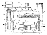
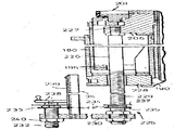
제1도는 본 발명에 따라 오른쪽에 도시된 프레스 공동의 로우더셈블리로 구성된 이중공동 타이어 경화 프레스 한측면의 부분정면도.1 is a partial front view of one side of a double cavities tire curing press consisting of a low assembly of press cavities shown on the right in accordance with the present invention;
제2도는 로우더어셈블리의 단면 및 이들을 부분절단한 확대측 정면도.2 is a cross-sectional view of the loader assembly and an enlarged side front view of the cut parts thereof.
제3도는 제2도의 선 3-3을 따라 절취한 로우더어셈블리의 확대부분 수평단면도.3 is an enlarged horizontal sectional view of the loader assembly taken along line 3-3 of FIG.
제4도는 제2도의 선 4-4에 따르는 로우더어셈블리의 부분평면도.4 is a partial plan view of the loader assembly along line 4-4 of FIG.
제5도는 제6도의 선 5-5를 따라 절취한 로우더어셈블리의 비이드 그립어셈블리와 트레드 레지스터어셈블리의 확대수직단면도.5 is an enlarged vertical cross-sectional view of the bead grip assembly and tread register assembly of the loader assembly taken along line 5-5 of FIG.
제6도는 제5도의 선 6-6를 따라 절취한 비이드 타이어셈블리와 트레드레지스터 어셈블리의 부분평면도FIG. 6 is a partial plan view of the bead tire assembly and tread register assembly taken along line 6-6 of FIG. 5. FIG.
제7도는 제6도의 선 7-7를 따라 절취한 비이드 그립어셈블리의 부분측면도.FIG. 7 is a partial side view of the bead grip assembly taken along line 7-7 of FIG.
제8도는 특수한 타이어 검출어셈블리를 도시하는 제6도의 선 8-8를 따라 절취한 비이드 그립어셈블리의 부분측면도.FIG. 8 is a partial side view of the bead grip assembly taken along line 8-8 of FIG. 6 showing a special tire detection assembly.
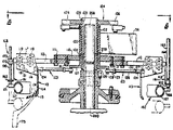
제9도는 제10도의 선 9-9를 따라 절취한 타이어프레스 중앙기계장치의 부분수직단면도.9 is a partial vertical sectional view of the tire press central machine cut along line 9-9 of FIG.
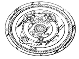
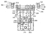
제10도는 제9도의 선 10-10을 따라 절취한 중앙기계장의 수평단면도.10 is a horizontal sectional view of the central machine taken along line 10-10 of FIG.
제11도는 제9도의 선 11-11를 따라 절취한 중앙기계장치의 또다른 수평단면도.FIG. 11 is another horizontal sectional view of the central machine taken along line 11-11 of FIG.
제12도는 특수한 하부비이드 클램프어셈블리와 그 작동기를 도시하는 제10도의 선 12-12를 윽라 절취한 중앙기계장치의 부분수직단면도.12 is a partial vertical cross-sectional view of the central machinery cut along line 12-12 of FIG. 10 showing a special lower bead clamp assembly and its actuator.
제13도는 하부비이드 클램프어셈블러의 특수한 조절될 수 있는 이동식 정지부를 도시하는제10도의 선 13-13을 따라 절귀한 중앙기계장치의 부분수직단면도.FIG. 13 is a partial vertical cross-sectional view of the central machinery cut along line 13-13 of FIG. 10 showing a special adjustable movable stop of the lower bead clamp assembler.
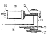
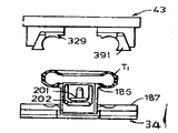
제14도는 하부토우링로우더의 구동하강어셈블리를 도시하기 위해 일부를 분해한 타이어프레스의 부분정면도.14 is a partial front view of the tire press in which part is disassembled to show the drive lowering assembly of the lower tow ring loader.
제15도는 제14도의 선 15-15를 따라 절취한 어셈블리의 부분평면도.FIG. 15 is a partial plan view of the assembly taken along line 15-15 of FIG.
제16도는 제15도의 부분확대도.FIG. 16 is a partial enlarged view of FIG.
제17도는 제14도의 선 17-17를 따라 절취한 에셈블리의 부분측면도.FIG. 17 is a partial side view of the assembly taken along line 17-17 of FIG.
제18도는 본 발명의 프레스와 중앙기계장지와 함께 사용되는 언로우더의 측입면도.18 is a side elevational view of an unloader for use with the press and central machine tool of the present invention.
제19도는 제18도의 선 19-19를 따라 절취한 언로우더의 확대단부입면도.FIG. 19 is an enlarged end elevation of the unloader taken along line 19-19 of FIG.
제20도-제30도는 양호한 프레스 작동 싸이클을 도시하는 개략도.20-30 are schematic diagrams showing a good press operating cycle.
본 발명은 일반적으로 타이어프레스 및 타이어를 성형하고 경화시키는 방법에 관한 것이며, 특히 자동 로우더 (loader)어셈블리를 사용하여 프레스속에 생형타이어를 주입시키고 타이어속에 경화 공기주머니를 주입시키는 방법과 프레스에 관한 것이다. 또한, 본 발명은 방사상 프라이 트럭타이어와 같이 큰 예성형(preshaepd)타이어의 로딩, 성형 및 경화에 관한 것이다,BACKGROUND OF THE INVENTION 1. Field of the Invention [0001] The present invention relates generally to tire presses and to methods of molding and curing tires, and more particularly, to a method and a press for injecting live tires into presses and injecting hardened air bags into tires using an automatic loader assembly. . The invention also relates to the loading, forming and curing of large preshaepd tires, such as radial fryer truck tires.
오늘날 대부분의 타이어 경화 프레스 및 방법들을 팽창성 공기주머니를 사용하는 바 이들이 생형타이어 내에서 방사상으로 팽창되어 있어 생형타이어 내부표면에 대해 성령 압력과 경화열을 가할 수 있었다. 대개 이러한 공기주머니는 하부프레스 중간부나 기저부에 장착되며 보통 이들내에 하우징된 프레스 중앙기계장치에 의해서 조종된다. 공기주머니에는 일정한 간격을 두어 예성형된 생형 타이어 비이드 사이의 구멍길이보다 상당히 긴 타이어의 원주 내부표면에 상응하는 축이 있기 때운에, 공지된 프레스들은 예성형된 생형타이어 속으로 공기주머니를 삽입시키기 위해 여러가지 형태의 중앙기계장치와 기술들을 사용하였다. 특히, 공지된 프레스들은 예를들어, 공기주머니를 상부 비이드주위의 타이어속에 삽입시키는 직립의 공기주머니 중앙기 계장치를 사용했다. 다른 것들은 공기주머니를 하부 비이드주위에 삽입시킨 것이다. 이러한 기술들에서는 사용중 공기주머니를 비대칭적으로 신장시키는 경향이 있어 공기주머니의 수명을 좌우하는 타이어의 성질에 미세하나마 약간의 변화를 야기시켰다. 또한, 이러한 기술에서는 공기주머니를 자주 교체해야했다. 한편, 상기 중앙기계장치를 사용하는 프레스는 단지 하나의 공기주머니 삽입기술에 따라서만 작동하며 다른 프레스 또는 중앙기계장치는 다른 형태의 공기주머기 삽입부가 제작자에 의해서 요구되는 경우에만 필요하였다.Most of today's tire hardening presses and methods use expandable air pockets, which are radially expanded within the green tires, allowing the application of holy pressure and hardening heat to the inner surface of the green tires. Usually these air bags are mounted in the middle or base of the lower press and are usually controlled by a press central mechanism housed therein. Known presses insert air bags into the preformed mold tires, since the air pockets have a corresponding spacing at regular intervals corresponding to the circumferential inner surface of the tire, which is significantly longer than the hole length between the preformed mold tire beads. Various forms of central machinery and technologies were used to achieve this. In particular, known presses have used, for example, an upright airbag central machine which inserts an airbag into a tire around an upper bead. Others are inserted around the lower bead. These technologies tend to asymmetrically stretch the airbag during use, resulting in minor changes in the properties of the tires that influence the life of the airbag. In addition, these techniques required frequent replacement of the pouch. On the other hand, the press using the central machine operates only according to one air bag insertion technique, and another press or central machine is needed only when another type of air bag insert is required by the manufacturer.
비록 어떤 하나의 공기주머니 삽입기술이 특수한 응용에서 유익하게 입증되었을지라도, 특히 타이어의 중간지점으로부터 대칭적으로 삽입하는 기술은 바람직한 것이다. 이러한 기술에 따라서, 생형타이어를 공기주머기 중앙에 위치시키거나 또는 역으로 위치시키고 공기주머니를 그속에서 팽창시켜 수직대칭의 횡축 평면을 따라 생형타이어와 우선 접촉시키고 이러한 평면으로부터 생형타이어 비이드를 향하여 외부로 점차적이고 대칭적으로 팽창시킨바, 공기주머니와 생형타이어 사이에 공기함정 (entrapment)이 생기지 않았고 공기주머니가 자체팽창하여 타이어속에 불규칙한 비대칭 성형응력이 발생하지 않았다. 그렇지 않은 경우, 타이어내에서는 공기주머니가 이동 및 신장운동을 하게 된다. 또한, 이러한 공기주머기 삽입기술은 공기주머니 팽창중에 공기주머기가 내부의 비대칭응력을 배제시키므로 공기주머기의 수명을 연장시킬 수 있었다.Although any one pouch insertion technique has proven to be beneficial in special applications, it is particularly desirable to insert symmetrically from the midpoint of the tire. According to this technique, the green tires are positioned in the center of the airbags or vice versa and the airbags are inflated therein to first contact the green tires along the vertically symmetrical transverse planes and from these planes towards the green tire beads. Gradually and symmetrically expanded to the outside, there was no entrapment between the airbag and the live tire, and the airbag self-expanded, resulting in no irregular asymmetrical molding stress in the tire. Otherwise, the pouch will move and stretch in the tire. In addition, this air bag insertion technology has been able to extend the life of the air bag because the air bag eliminates the asymmetrical stress during the expansion of the air bag.
종래에는, 이러한 대칭형 공기주머기를 삽입시키는데 있어서 공기주머기를 팽창시키전 및 팽창시 생형 타이어 센터나 크라운을 프레스에 적합하게 위치시킨다는 확신을 가지고 생형타이어를 프레스에 자동적으로 그리고 반복해서 적재시켜야 하는 불가능한 문재가 있었다. 이러한 문제는 예성형된 생형차이어의 측벽이 매우 가요성으로서 경화되는 동안 저장소에서 크기가 변형될 수 있다는 사실에서 발생한 것이다. 근래에는 대부분외 자동로우더를 사용하지 않는 경우 그 상부비이드로 생형타이어를 집어올리기 때문에, 생형타이어의 횡축중간 평면이 삽입전이나 삽입중에 공기주머니에 관계되는 공지 또는 주어진 위치에 있게 된다는 확신이 없다. 그결과, 타이어에 대해 공기주머니를 비대칭적으로 위치시키는 것은 가능한 것이다.Conventionally, in order to insert such a symmetrical air blower, an impossible door material has to be automatically and repeatedly loaded onto the press with the assurance that the air tires are properly positioned at the press before and during the expansion. There was. This problem arises from the fact that the sidewalls of the preformed green tires are very flexible and can change in size in the reservoir during curing. In recent years, since most of the autoloader is not used to lift the green tire with its upper bead, there is no certainty that the horizontal axis of the flat tire is in a known or given position relative to the air pocket before or during insertion. As a result, it is possible to position the air pocket asymmetrically with respect to the tire.
프레스속에 타이어를 적재시키는 동안에, 타이어와 공기주머니를 결합시키는 몇가지 방법이 시도되어 왔다. 한 방법은 중앙기계장치가 그구조 적대칭평면에 의해 차단된 위치에서 공기주머니를 생형타이어트레드와 방사상으로 외부로 기계적으로 접촉되도록 하는 다소 복합한 링크어셈블리를 포함하고 있음을 설명한 것으로 미합중국특허 제3,790,656호에 명시되었다. 링크어셈블리와 공기주머니에 대해 생형타이어를 비대칭적으로 위치시키면 프레스폐쇄중에 생형타이어를 지지하는 공기주머니가 비이드시이트와 어긋나게 배열되기 때문에 프레스가 폐쇄됨에 따라 그 각각의 시이트위에 생형타이어 비이드가 부적당하게 위치하게 된다.While loading tires into presses, several methods of engaging tires and pouches have been tried. One way is to explain that the central mechanism includes a rather complex linkage assembly that allows the air pocket to mechanically contact the live tire tread radially outward at a location blocked by its structural symmetrical plane. United States Patent No. 3,790,656 Specified in the heading. The asymmetrical positioning of the green tires relative to the link assembly and air pockets causes the air pockets to support the green tires to be aligned with the bead sheet during press closure, so that the green tire beads are not appropriate on each sheet as the press is closed. Will be located.
또 다른 시도는 미합중국특허 제3,837,770호에 명시된 바와 같이 공기주머니를 중앙에 삽입시키는 것이다. 그러나, 공기주머니를 팽창시키고 조종하기에 앞서 폐쇄된 프레스속의 성형물 각각의 비이드시이트로 그 상부 및 하부비이드에 지지시켰딘 것이다. 상기 특허는 어떻게 생형타이어가 자동적으로 들어올려지고 공기주머니 삽입전과 삽입중 및 폐쇄전애 생형타이어가 프레스속에 적합하게 놓여지는가에 대해서는 언급하고 있지 않다.Another attempt is to insert the air pocket in the center, as specified in US Pat. No. 3,837,770. However, prior to inflating and manipulating the airbag, the bead sheet of each of the moldings in the closed press was supported by its upper and lower beads. The patent does not mention how the green tires are automatically lifted and how the green tires are properly placed in the press before, during and after the airbag insertion.
팽창성 공기주머기를 사용가는 공지된 프레스에서의 다른 문제는 예성형된 생형타이어속으로 공기주머니를 삽입시키는 중에 타이어의 비이드부에 손상이 생긴다는 것이다. 타이어속으로 공기주머니를 찔러 넣을때, 공기주머니는 하나의 비이드위에서 구르는바, 이러한 구름작용으로 인해 비이드가 변형되거나 손상되어 결함있는 타이어를 생산한다. 공지된 프레스의 또다른 결점은 다른 크기의 타이어를 성형하고 경화시히는 프레스 및 로우더어셈블리를 조절하는데 어려움이 있고, 필요할패 공기주머니를 교체시켜야 하고, 타이어로부터 공기주머니를 제거시키는 진공시스템을 필요로 하고, 비싼지지어셈블리 및 조정기를 사용해야 하며, 프레스에서 발생되는 고온을 견더어 낼 수 있는 특수한 시이일 및 패킹을 필요로 하고 있는 것이다. 더우기, 공기주머니삽입 및 프레스의 폐쇄전에 중앙기계장치 및 로우더어셀블리와 프레스 성형부품에 대해서 타이어를 정확한 크라운에 놓이게 할 수 없었기 때문에 본 발명의 기술을 이루기가 어려웠다. 또한, 중앙기계장치가 프레스로부터 제거되기 전에 중앙기계장치를 해체시켜야 하는 경우가 있기 때운에 많은 프레스에서 중앙기계장치를 사용하기가 어려웠다.Another problem with known presses using inflatable airbags is that damage occurs to the bead portion of the tire during insertion of the airbag into the preformed green tire. When a pouch is inserted into the tire, the pouch rolls over one bead, which causes the bead to deform or damage, producing a defective tire. Another drawback of known presses is the difficulty in adjusting presses and loader assemblies for forming and curing tires of different sizes, requiring replacement of air bags and requiring a vacuum system to remove air bags from the tires. Expensive support assemblies and regulators must be used, and special seals and packings are needed to withstand the high temperatures generated in presses. Moreover, the technique of the present invention was difficult to achieve because the tires could not be placed in the correct crown for the central machinery and the loader assembly and the press-formed parts prior to inserting the pouch and closing the press. In addition, it has been difficult to use a central machine in many presses because it may be necessary to dismantle it before the central machine is removed from the press.
상기와 같이, 본 발명의 주목적은 타이어의 균일성을 증진시키고 공기주머니의 수명을 증가시키기 위해 크라운의 중앙으로부터 공기주머니를 생형타이어속에 대칭적으로 삽입시키는 타어경화프레스를 제공하는 것이다.As described above, it is a main object of the present invention to provide a tare hardening press for symmetrically inserting an air bag into a live tire from the center of the crown to improve the uniformity of the tire and increase the life of the air bag.
또한 본 발명의 중요한 목적은 타이어가 로우더에 의해서 파지되는 동안에 상기 삽입을 수행하고, 공기주머니 삽입부에 가요성을 부여하는 타이퍼프레스를 제공하고, 공기주더니 삽입중에 생형타이어를 견고히 파지시키고 생형타이어비이드를 손상시키지 않는 타이어프레스를 제공하고, 공기주머니가 용이하계 삽입되도록 생형타이어가 열려져 있는 타이어프레스를 제공하고, 로우더가 상부비이드를 파지하여 그것과 일치된 상태에서 공기주머니를 삽입하고 수직이동 로우링이 하부비이드를 파지하여 그것과 일치된 상태에서 중간평면을 지지시키는 것이고, 로우더와 하부로우링이 함께 수직이동하는 프레스를 제공하고, 공기주머니를 수축시키는 진공시스템을 필요로 하지 않는 프레스를 제공하고, 높이를 감소시키고, 프레스속레서의 공기주머니 교환을 용이하게 하고, 중앙기계장치에서 표준형 작동실린더를 사용할 수 있는 프레스를 제공하고, 타이어의 크기에 따라 조정이 용이한 프레스를 제공하고, 타이어의 크기에 따라 조정이 용이한 프레스를 제공하고, 공기주머의속의 경화유체가 다른 매체나 물로 오염되지 않도록 작동기를 공기주머니로 부터 멀리 위치시킨 프레스 중앙기계장치를 제공하고, 성형부로부터 경화된 타이어를 쉽게 회수할 수 있는 프레스를 제공하고, 정비가 용이한 프레스를 제공하는 것이다.In addition, an important object of the present invention is to perform the insertion while the tire is gripped by the loader, to provide a type of press to impart flexibility to the air bag insert, to firmly grip the green tire during the air bag insertion, Provides a tire press that does not damage the bead, provides a tire press with the green tire open so that the air bag is easily inserted, and inserts the air bag while the loader holds the upper bead and matches it The moving low ring grips the lower bead to support the intermediate plane in coincident with it, providing a press in which the loader and the lower row ring move vertically together, and do not require a vacuum system to deflate the air pockets. Provides presses, reduces height, pneumatic packer Provides a press that can be easily exchanged, can use a standard operation cylinder in the central machine, can be easily adjusted according to the tire size, provides a press that can be easily adjusted according to the tire size, Provides a press central machine that moves the actuator away from the air bag so that the hardening fluid in the air bag is not contaminated with other media or water, and provides a press for easily recovering the cured tire from the molding part. It is to provide an easy press.
또한, 생형타이어축을 정확하게 처치시키고 횡축중간평면을 지지하는 프레스용 로우더를 제공하고, 중앙기계장치를 생형타이어의 적재 및 공기주머니 삽입중에 로우더 중앙에 정확히 위치시키고 타이어를 프레스가 폐쇄되는 동안 성형부 중앙에 정확히 위치시킬 수 있고 이러한 정확한 중앙위치설정이 기계적인 정지부 또는 다른 위치설정장치에 의해서 이루어지는 프레스를 제공하는 것이다.It also provides a press loader for precisely treating the mold tire shaft and supporting the transverse midplane, positioning the central machine precisely at the center of the loader during loading of the tire and inserting the pouch, and placing the tire in the center of the forming part while the press is closed. It is possible to provide a press which can be precisely positioned at the center and this exact centering is done by a mechanical stop or other positioning device.
끝으로, 본 발명의 중앙기계장치를 사용라는 프레스용 언로우더 (unloader)를 제공하는 것이다.Finally, to provide an unloader for presses using the central machine of the present invention.
본 발명의 상기 목적과 다른 목적을 이루기 위하여, 본 발명의 원리를 이용하는 타이어프레스는 일반적으로 생형타이어의 상부비이드와 결합하는 비이드그립과, 상부비이드와 트레드사이를 예정된 간격으로 유지시켜 프레스트레드의 횡축대칭평면을 정확하게 일치시키고 트레드의 상부견부를 결합시키는 트레드위치 설정장치 나 레지스터로 구성된다.In order to achieve the above object and other objects of the present invention, a tire press using the principles of the present invention is generally a bead grip coupled to the upper bead of the green tire, and the press between the upper bead and the tread by maintaining a predetermined interval It consists of a tread positioning device or resistor that precisely matches the transverse symmetry plane of the red and engages the upper shoulder of the tread.
트레드 레지스저에는 비이드그립의 교호방사상 슬라이드바아에 선별장착된 1이상의 피스톤실린더 어셈블리에 의해 축상이동을 하는 종심링이 장착되어 있는데, 상기 슬라이드바아는 방사상으로 팽창될때 생형타이어의 상부비이드를 들어올리고 방사상으로 인입될때 비이드를 해체시켜 주는 각각의 로우더슈즈를 따라 방사상으로 슬라이딩 이동되도록 지지해주고 있다. 다른 교호슬라이드 바아에는 상기 예정된 간격을 정확히 결정해주는 조절가능한 기계적 정지부가 1이상 장착되어 있다.The tread register is equipped with a longitudinal ring which is axially moved by one or more piston cylinder assemblies that are selectively mounted on an alternate radial slide bar of the bead grip, which slide bar lifts the upper bead of the live tire when radially inflated. It is supported to slide radially along each of the loader shoes which release the beads when they are raised and radially pulled in. Other alternating slide bars are equipped with one or more adjustable mechanical stops that accurately determine the predetermined spacing.
비이드그립 및 트레드 레지스터는 프세스용 로우더에 의해 바람직하게 작동되는바, 상기 로우더는 비이드그립과 트레드레지스터를 타이어 픽업위치인 프레스 전방으로부터 타이어 적재일치인 프레스 중심으로 이동시키고, 생형타이어의 하부비이즈를 수직이동 토우링의 상부 또는 인접부에 위치시킨 후, 상기 비이드그립과 트레드레지스저 및 하부토우링을 견고하게 고정되어 있는 생형타이어과 함께 하강시키므로써 하부토우링을 프레스의 하부성형부에 안착시킴과 동시에 트레드의 횡축중간평면을 개별작동식 상부공기주머니 비이드클램프와 하부공기주머니 비이드클램프사이의 프레스하반부 중앙기계장치에 장착된 공기주머니의 횡축중간평면과 합치시키는 수단으로 구성된다. 상부비이드 클램프는 축방향이동식 중앙포스트상에 장착되며, 상기 중앙포스트에는 중앙기계장치 및 비이드그립의 중심축, 즉 공기주머기와 생형타이어의 중심축과 정확히 일치되도록 비이드그립의 파일럿부싱에 수용가능한 상향돌출파이럿이 부설된다. 생형타이어가 비이드그립과 트레드레지스저에 의해 개방되어 공기주머니의 축방향과 횡축방향으로 위치하며 공기주머니는 팽창되어 중간평면을 따라 트레드와 접촉한 후 상기 정면으로부터 타이어비이드쪽으로 점진적이고 대칭적이게 외부로 이동하여 삽입된다. 생형타이어는 중앙기계장치와 하부토우링에 의해 파지되고 상부성형부의 중간부는 프레스에 접근되도록 파일럿부싱이 있어 프레스폐쇄시 상부성형부에 생형타이어를 안착시키기 위한 중앙기계장치의 각축과 상부성형부를 결합시켜 준다.The bead grip and tread register are preferably operated by a process loader, which moves the bead grip and the tread register from the press front at the tire pickup position to the press center at the tire loading level, After placing the beads on the upper or adjacent part of the vertically moving tow ring, lowering the bead grip, the tread register and the lower tow ring together with the fixed tire fixedly, thereby lowering the tow ring to the lower part of the press. It consists of a means to fit the transverse midplane of the tread with the transverse midplane of the airbag mounted on the central machine unit of the lower half of the press between the individually operated upper airbag bead clamp and the lower airbag bead clamp. . The upper bead clamp is mounted on an axially movable central post, which is attached to the pilot bushing of the bead grip so that it is exactly aligned with the central axis of the central machine and the bead grip, that is, the central axis of the pneumatic and live tires. An acceptable upward protrusion pilot is placed. The green tire is opened by the bead grip and the tread register and is positioned in the axial and transverse directions of the air pocket. The air pocket is expanded to contact the tread along the middle plane and then gradually and symmetrically from the front side toward the tire bead. This is moved outside and inserted. The green tires are gripped by the central machine and the lower toe ring, and the intermediate part of the upper forming part has a pilot bushing to access the press, so that each shaft and the upper forming part of the central mechanical device for seating the forming tire on the upper forming part is closed when the press is closed. Let it be.
본 발명에 따라서, 하부공기주머 니비이드클램프는 중앙포스트위의 슬리이브위에 장착되고 슬리이브 및 중앙포스트는 하부프레스 중간부에 제거될 수 있게 고정된 웰(well)속에서 수직으로 삽입이동되도록 설치된다. 상기 웰은 그속에서 지지되며 하부토우링을 고정시킨 이동식 슬리이브가 수직으로 삽입 이동되도록 한다. 공기주머니 비이드클램프와 이동식 웰은 웰의 저부판에 장착된 유압작동기에 의해 작동되는바, 상기 웰의 저부판에는 경화시에 발생한 열로부터 유압작동기를 격리시키는 냉각제 순환통로가 있다. 중앙기계장치부는 상기 웰에 의해 작동되므로 쉽게 제거되고 정비가 용이하다.According to the present invention, the lower air pocket nitride clamp is mounted on the sleeve above the center post and the sleeve and the center post are installed to be vertically inserted into a fixed well to be removed in the middle of the lower press. do. The well is supported therein to allow the movable sleeve holding the lower toe ring to be inserted and moved vertically. The airbag bead clamp and the movable well are operated by a hydraulic actuator mounted on the bottom plate of the well, and the bottom plate of the well has a coolant circulation passage that isolates the hydraulic actuator from heat generated during curing. The central mechanism part is actuated by the well so that it is easily removed and easy to maintain.
본 발명은 로우더 및 언로우더를 지니는 타이어프레스와 부품 및 상호이동할 수 있는 프레스부품을 정확히 위치시켜주는 여러 가지의 조절가능한 기계걱 정지부와 위치설정장치로 구성되는 바람직한 것으로 이들 모두는 하기의 상세한 설명에서 완전히 설명된다.The present invention is preferably composed of a tire press having a loader and an unloader and various adjustable applicator stops and positioning devices for accurately positioning the pressable parts and interoperable presses, all of which are described in detail below. Is explained fully in
상기의 목적을 완성시킨, 본 발명은 본 발명의 실시예를 상세히 도시하는 첨부된 도면과 청구범위 및 하기의 명세에서 지적되고 상세히 설명되고 있으나, 이는 본 발명의 원리가 사용된 여러방법중 몇가지 방법만을 도시한 것이다.Although the invention has been pointed out and described in detail in the accompanying drawings, claims and the following specification, which illustrate embodiments of the invention in detail, it is a method of several of the various methods in which the principles of the invention have been employed. It shows the bay.
제1도를 참조하면, 트럭타이어와 같은 큰 타이어를 성형하고 경화시키기에 특히 알맞은 이중공동타이어 경화프레스의 오른쪽 측면(30)이 도시되어 있다. 프레스(30)는 하부프레스 중간부(34) 하부측면에 고정된 발판(32)에 의해서 바닥(31)위에 장착된다. 하부프레스 중간부(34)에는 하부프레스 중간부(34)의 프레스 부품을 보호하는 원통형 환상판(35)에 의해서 가려진 측판 및 수평프레임부재로 구성, 조립된 프레임이 있다. 환상판(35)은 이후에 상세히 설명되는 중앙포스트 어셈블리 또는 기계장치(38)과 같이 하부프레스 중간부(34)속의 내부프레스 부품으로 접글하는 접근구멍(37)을 그 전방 및 후방측면에 지니고 있다. 하부프제스 중간부의 환상판(35)사이를 고정시키는 각 공동(제1도의 왼쪽)은 수직하게 공간을 형성하며 브래킷(39 및 40)들은 수직기등(41)을 지지한다. 수평비임 또는 요오크(42)는 수직기등(41)에 장착되어 있으며, 각각의 성형공동위에 돌출되어 있고 그 말단부에는 상부프레스 성형중간부(43)가 달려있다.Referring to FIG. 1, there is shown the
긴 행정퍼스톤-실린더어셈블리(44)는 수직기등(41)의 전방프레스 공간사이에 위치하고 있는데 그 실린더단부(45)는 트러니언 어셈블리(47)에 의해 프레임브래킷 (46)에 장착되어 있고, 그 로드단부(48)는 수평 비임(42)으로부터 전방으로 뻗어있는 수평비임 돌출부(50)에서 클레비스(49)에 의해 수평비임 (42)에 연결되어 있다.The long stroke cylinder-cylinder assembly 44 is located between the front press spaces of the vertical lamps 41 whose cylinder end 45 is mounted to the frame bracket 46 by the
피스톤실린더 어셈블리 (44)가 작동하면 수직기등(41)을 따라 수평비임 (42)이 수직이등하고 상부성형 프레기스중간부(43)가 수직이동하여 프레스가 개폐된다. 프레스가 폐쇄되면, 쇄정링(51)이 회전하여 하부프레스 중간부(34)에 상부프레스 성형중간부(43)가 쇄정된다. 그후, 유압압축실린더(52)가 작동되면서 성형중 간부속에 이송된 성형부가 본 출원인의 "유압타이어프레스"란 명칭으로 출원된 특허출원서에서 도시되고 설명된 방법으로 폐쇄하고 적재된다. 양호한 형태의 프레스가 도시되고 설명되었으나, 본 발명의 원리가 다른 형태의 프레스에서도 사용될 수 있다는 것을 알 수 있다.When the piston cylinder assembly 44 is operated, the
제1도를 다시 참조하던, 프레스(30)에는 생형타이어를 픽업위치로부터 프레스전방의 프레스공동속으로 적재시키는 로우더어셈블리(54)가 있다. 프레스에는 항상 프레스의 다른 타이어공동을 적재시키는 제2의 유사한 로우더어셈블리가 있다. 도시된 바와 같이, 로우더어셈블리는 스윙아암형태로서, 하기에 설명되께지만, 수직 및 수평으로 스윙이동을 하는 로우더기둥(58)위에 장착된 로우더아암 또는 프레임(56)의 말단부에 달려있는 비이드그립 어셈블리 (55)를 포함한다. 로우더기둥(58)은 도시된 것과 같이 하부프레스중간부(34)의 측면위에 편리하게 장착되거나 바닥위에 독립적으로 장착된다.Referring again to FIG. 1, the
제2도 내지 제4도를 참조하면, 로우더아암(56)은 수직공간을 형성한 슬라이드블럭(61 및 62)을 상호연결시키는 수직신장사각관(60) 정부에 장착되어 있는데, 상기 블럭들은 상기 기둥(58)의 브래킷(65 및 66)사이에 상부와 하부가 결합된 피봇샤프트(64)상에서 수직이동한다. 상부 및 하부의 피봇트판(69 및 70) 각각은 피봇샤프트(64)에 결합되어 피봇이동을 한다. 일반적으로 피봇판은 장방형으로서 이들의 돌출단사이에서 피봇샤프르(64)와 평행하게 공간을 형성한 가이드로드(71)를 지지한다. 가이드로드(71)는 로우더아암(56)속의 부싱(72)을 통하여 뻗어있으며 로우더아암을 피봇샤프트(64) 및 피봇판(69 및 70)과 공동피붓시키고 있다.2 to 4, the
제3도에 잘 도시되듯이, 가이드로드(71)와 대향하는 하부피봇판(70)의 단부에는 홈이 파진코너(74)가 있는데, 이로부터 러그(75)가 뻗어있으며 이곳에 플레비스(76)에 의해 수평피스톤 실린더어셈블리(77)가 고정된다. 피스톤-실린더어셈블리(77)의 블라인드 단부는 피봇(78)에서 하부프레스 중간부의 환상핀(35)에 고정된 장착브래킷(79)과 연결된다. 제3도에 도시된 바와 같이 브래킷(79)은 장착부로서, 로우더기둥(58)이 하부프레스 중간부에 즉, 쥠쇠(81)에 의해서 브래킷(79)의 수직플랜지판(82)에 고정된 수직장착판(80)을 갖는 기둥이 고정된 것이다.As shown in FIG. 3, at the end of the
피스톤-실린더 어셈블리(77)가 인입될때, 피봇판(69 및 70)은 각각 제3도 및 제4도의 실선위치로 회전하며 이에따라, 로우더아암(56)이 회전하면서 비이드그립 어셈블리(55)를 프레스전방의 생형타이어 픽업 위치로 배열시킨다. 퍼스톤-실린더 어셈블리가 연장되면 상기 대향방향으로 피봇판이 점선위치로 회전하며 이에따라, 로우더아암이 비이드그립 어셈블리를 개방된 프레스의 적재위치로 회전시킨다. 로드의 연장은 점선위치로 도시된 바와 같이 기둥(58)위에 정지판(84)을 접속시키는 하부판(70)의 돌출단부에서 조절 가능한 정지부(83)에 의해서 제한된다. 정지부는 적재위치에 있을때 프레스축상 중앙선의 밀접한 공차내에 비이드그립 어셈블리(55)의 축상중앙선이 위치되도록 조절된다.When the piston-
제4도에 잘 도시된 바와 같이, 상부피봇판(69)으로부터 상부로 수직하게 연장하는 핀(87)을 결합시키는 상부브래킷 (65)위에 장착된 리미트스위치 (85 및 86)는 로우더아암이 적재 또는 픽업위치에 있을 때를 지시해 준다.As shown in FIG. 4, the limit switches 85 and 86 mounted on the
로우더아암(56)은 트러니온(89)에 의해 하부피봇판(70)에 장착된 실린더부의 수직피스톤실린더 어셈블리(88)에 의해 수직이동한다. 퍼스톤-실린더어셈블리 (88)의 로드단부는 클레비스(90)에 의해, 로우더아암(56)의 하부측면측 사각형관(60)의 한 측면에 고정된 이음판(91)에 연결된다. 피스톤-실린더어셈블리(88)가 연장되면 제2도에 도시된 점선위치(92)로 로우더아암(56)이 이동하고 실선으로 도시된 위치로 인입된다.The
한쌍의 리미트스위치(93 및 94)는 로우더아암(56)의 상승 및 하강위치를 지시한다. 상부 리미트스위치(93)는 상부퍼봇판(69)에 달려있는 브래킷 (95)위에 장착되고 사각형 관(60)에 고정된 캠판(96)과 연결된다. 하부리미트스위치(94)는 하부피봇판(70)위의 수직연장부(97)위에 장착되고 사각형관(60)위의 ,수직트랙(99)속에 조절가능하고 미끄러질 수 있게 고정된 조절가능한 캠판(8)과 결합된다.The pair of
제5도 내지 제8도를 참조하면, 바이드그립어셈블리 (55)에는 로우더아암(56)의 말단부에 고정된 수직돌출형의 허브(105)가 있다. 허브(100)의 상부 및 하부단부는 로우더아암 넘어로 돌출되어 있으며 그속에는 수직하게 연장하는 관형핀(103)이 뻗어있고 이를 통해, 부싱(102)이 플랜지 결합하다. 대향적으로 뻗어있는 같은 길이의 두 방사상아암(105 및 106)을 포함하는 수평구동판 또는 크랭크(104)는 허브(100)을 넘어서 돌출되어 있는 그 상단부에서 관형핀(103)과 결합된다. 관형핀(103)의 하단부는 허브(100)아래로 돌출되어 있으며, 여지에 원형판(107)이 결합된다. 구동관(104)과 원형판(107)은 스댑링 또는 리테이너 (108) 및 (109)에 의해서 관형핀(103)위의 제위치에 파지되며 함께 작용하여 허브(100)의 관형핀(103)을 지지한다.5 to 8, the
로우더아암(56)하부에 있는 허브(100)의 하단부는 그위에 위치한 플랜지형성링 (110)에 고정되어 원형판(107)을 넘어 방사상으로 외부로 뻗어있다. 6개의 똑같은 원주간격으로 방사상으로 연장하는 수평슬라이드바아(112)는 쥠쇠(111)에 의해서 링플랜지 (110)의 하부측면에 고정된다. 각각의 슬라이드바아 112에는 로우더슈우(113)가 장착되어 있는데, 이들 각각은 형태가 동일하므로 하나만을 상세히 설명하겠다.The lower end of the
각각의 로우더슈우(113)은 비교적 얇은 게이지금속으로 만들어진 것으로 제6도에서 도시된 것같이 약간 완곡한 수직연장하는 스핀판(114)을 포함한다. 스핀판(114)의 하부는 외부로 약간 굽혀져 있어 타이어의 상부비이드를 결합시키는 립(115)을 형성한다.Each
스핀판의 곡률은 로우더에 의해서 수용된 타이어크기의 범위에 의해서 결정된다. 스핀판의 상부는 평형측판(117)을 연결하는 크로스바아(116)에 용접된다. 또한 측판(117)은 4개의 너트와 볼트쥠쇠(119)에 의해서 결합되고, 쥠쇠의 생크는 압축슬리이브 또는 스페이서(120)를 통과한다. 이러한 스페이서(120)는 슬라이브바아(112)를 제한되는 낮은홈의 자체배열 슬리이드블록(121)뒷면에 있는 반원형 홈속에 끼워 맞추어진다. 슬라이드블록(121)은 슬라이드바아의 대향면상에 한싼으로 배열되어 있어 방사상으로 미끄럼이동시키는 슬라이드바아의 본 위치에서 로우터 측판을 파지한다.The curvature of the spin plate is determined by the range of tire sizes accommodated by the loader. The upper portion of the spin plate is welded to the
각각의 로우더슈우(113)는 연결로드 또는 링크(123)에 의해서 회전판(107)에 연결된다. 각각의 연결로드(123)에는 각단에 아이 (eyes : 124 및 125)를 포함하는바, 이들은 각각, 크로스바아(116)상부 및 회전판 (107)하부에 교대로 힌지되어 연결된 생크(126)에 나선연결되어 있다. 각각의 로드유효길이는 그 각각의 쇄정너트(130 및 131)가 풀려질때 아이 (124 및 125)에 대해 생크(126)를 회전시켜서 조절한다.Each
제6도에서, 슈우(113)는 방사상으로 연장하는 연결로드(123)에 의한 이들이 최대직경으로 도시되어 있다. 제6도에 도시된 바과 같이 시계방향으로 원형판(107)이 회전하면, 연결로드(123)가 관형된(103)의 반경에 대한 일반각으로 균일하게 이동하여 최소직경의 슬라이드바아(112)를 따라 슈우(113)를 방사상으로 인입시킨다.In FIG. 6, the
원형판(107)은 고기식 피스톤-실린더 어셈블리 (133)에 의해서 회전하며, 어셈블리로드에는 135에서 부동판(104) 아암(105)에 피봇연결된 클레비스(134)가 설치되어 있다. 퍼스론-실린더 어셈블리 (133)의 블라인드단부는 로우더아암(56)위에 설치된 브래킷 (137)에 135에서 퍼봇연결된다. 어셀블리(133)는 로우더 슈우(113)를 방사상으고 인입시키고, 반면에 반대로 로우더슈우(113)를 방사상으로 연장시킨다. 유사하게 구성된 타이어딩척의 보다 상세한 기술은 1979년 11월 19일자 출원된'"타이어로우더"라는 명칭의 아난드피싱의 미합중국특허원 제95,586호끼 참조되어 있다.The
피스톤 실린더 어셈블리 (133)의 행정은 일반적으로 제6도에 138로 도시된 행정제한 어셈블리에 의해 양방향에서 제한을 받는데, 상기 제한 어셈블리는 140에서 아암(106)에 피봇연결된 나선행정 리미터 로드(109)를 구성한다. 로드(1390)위에 설치된 내부나선형 슬리이브(141)는 로우더 아암(56)에 고정된 정지브래킷 (143)의 큰 구멍을 통하여 연장되어 있으며 겅지브래킷 (143)의 양 측면위의 정지칼러 (144 및 145)를 상호연결시킨다.The stroke of the
따라서, 정지브래킷과 정지칼러를 각각 연결하면, 피스톤-실린더어셈블리 (133)로드의 최대주행이 결정된다. 더우기, 글리이브는 로드 에위서조절되어 다른 크기의 타이어에 대한 로우더슈우의 최대직경을 결정하는 로드의 최대허용연장을 정확히 결정해준다. 일단 조절되면, 로드위의 슬리이브 위치는 칼러(144및 145)속에 배치된 구멍속에 제거될 수 있게 수용된 저지구핀(146) 수단에 의해 쇄정되고 정지브래킷 (143)속의 큰 구멍을 통과하는바, 로드위슬리이브의 회전을 저지해준다.Therefore, when the stop bracket and the stop collar are respectively connected, the maximum running of the piston-
바람직하치 리미터로드(139)위에서 1/4회전하므로서 슬리이브를 조절하는 원주상으로 똑같이 칼러속에 간격진 4개의 구멍이 있다.There are four equally spaced holes in the collar equally circumferentially for adjusting the sleeve by making a quarter turn above the
제6도 및 8도에 잘 도시된 바와같이, 비이드 그립어셈블리(55)는 147로서 도시된 타이어 검출어셈블리를 포함한다. 이러한 어셈블리는 교대로 링플랜지(110)위에 장착된 방사상의 연장플랫포옴(149) 돌출단부에 장착된 수직하게 뻗어있는 관형가이드(148)를 포함한다. 로드 또는 관(52)은 방사상의 연장 수평로드 또는 관(152)을 그 하단부에 고정시키고 있으며 가이드 슬리이브(148)속에서 이동가능하다. 트립판(153)은 가이드(154)페 의해서 수직이동하며 관(150)의 상단부에 적합하게 고정된다. 로드(150)는 트립판(153)에서 조절되는 바, 관(152)이 생형타이어의 측벽과 언결되기전에 로우더 슈우(113) 립 (115)이 생형타이어를 내측에 위치하게 한다. 로우더 어셈블리가 더욱 하강함에 따라 트립판(153)운 수직하게 하방으로 밀려나가 플랫포옴(149)데 장착된 스위치(156)를 작동시키는 바, 로우더가 로우더 슈우를 팽창시키기 위해 생형타이어와 관계하는 적합한 위치에 있음은 물론 생형타이어가 존재함을 지시한다.As best shown in FIGS. 6 and 8,
로우더는 프레스 전방의 픽업위치로 회전하고 예를들어 프레스전방의 스탠드위에 지지된 생형타이어의 상단부속에 인입된 로우더슈우를 위치시키기 위해 하강될 수 있다. 로우더 슈우가 방사상으로 팽창하면 로우더가 상승되어 생형타이어 상부 비이드의 축상내부를 결합시킨다. 슈우가 생형타이어의 상부 비이드를 결합시키고 상승합에 따라 이들은 비이드그림 어셈블리에 대해 상부비이드를 축상으로 중앙에 위치시킨다.The loader can be lowered to rotate to the pick-up position in front of the press and for example to place the loader shoe drawn on top of a live tire supported on a stand in front of the press. When the loader shoe expands radially, the loader rises to engage the on-axis interior of the green tire upper bead. As the shoe engages the top beads of the live tires and rises, they center the top beads axially with respect to the bead figure assembly.
로우더 슈우가 팽창 상승하어 생형타이어 상부 비이드의 축상내부를 파지할 때 생형타이어의 상부비이드가 비이드그립 어셈블리(55)에 대해 중앙에 위치하지만, 타이어 트레드의 횡축 중간 평면은 경화되지 않은 타이어 측벽의 가요성으로 인하여 정확하게 일치될 수 없다. 이러한 문제는 타이어가 상기 측벽을 뒤틀리게 하는 이들의 측면상에 종종 저장되기 때문에 대칭형의 트레드 횡축 평면이 로우더슈우에 의해서 파지된 타이어의 상부 비이드 평면으로 기울어질 정도로 악화된다. 이러한 문제를 완화시키기 위해서, 제5도의 도번 160으로 표시된 트레드 레지스터 어셈블리가 장치되어 있다. .When the loader shoe expands and grips the on-axis of the green tire upper bead, the upper bead of the green tire is centered with respect to the
제5도 및 제6도에 도시된 바과 같이, 트레드 레지스터 어셈블리(160)에는 방사상으로 외부로 뻗은 짧은 다리부(152)와 수직하게 뻗는 긴 다리부(163)를 지니는 6개의 L형 장착 브래킷(161)이 있는데, 긴 다리부는 이들의 상부에서 쥠쇠(164)에 의해 각각 슬라시드 바아(112)단부에 고정된다. 수직하게 뻗버있는 공기식피스톤-실린더 어셈블리 (165)는 각각의 교호 브래킷의 짧은 다리부(162)위에 장착되고, 로드는 브래킷 (161)으로부터 하부로 연장되어, 그 하단부에서 관형링 또는 트레드 포지셔너 (167)위의 방사상으로 있는 뻗는 러그(166)에 연결되는데, 이러한 링은 비이드 그립 어셈블리 (55)와 동축상에 놓인다. 피스톤-실린더어셈블리 (165)의 하향행정 및 트레드링(167)의 하향이동을 제한하는 조절가능한 링 정지부(168)는 다른 교호 브래킷에 장찰된다. 각각의 정지부(168)는 트레드 중앙링 (167)위의 방사상으로 돌출되어 있는 러그(171)에 고정된 나선형 수직로드(170)을 구성한다. 로드는 브래킷의 짧은 다리부(162)속의 구멍을 통하여 뻗어있으며 링 (167)과 대향하는 브래킷의 측면위에 조절가능한 정지너트(172)과 쇄정너트(173)가 설치된다. 피스톤-실린더 어셈블리(165)가 인입되면, 트레드 위치링 (167)은 방해가 되지않는 적합한 위치에 놓이게 되는바, 생형타이어 T속으로 로우더 슈우가 삽입되어 이들의 상부비이드(174)를 파지한다. 제5도의 왼쪽에 도시된 바와같이 생형타이어가 그 상부비이드에 의해서 들어올려져 파지되면, 피스톤-실린더 어셈블리(165)가 팽창하여 트레드 위치링(167)을 하방으로 이동시키므로서 생형타이어 트레드 부분(175)의 상부 견부를 결합시키고 제5도의 점선으로 표시된 바와 같이 상부비이드와 트레드부분간의 예정된 거리를 밀어내는바, 타이어의 뒤틀림을 배제시키고 대칭형의 횡축트레드 평면을 정확하게 위치시킨다. 이처한 예정된 거리는 브래킷 (161)의 짧은 다리부(162)와 조절너트(172)의 결합에 의해서 정확히 결정된다. 이러한 방법으로 대칭형의 횡축 트레드 덮개 평면은 교대로 프레스로 회전될 수 있는 비이드그립 어셈블리에 정확히 위치되고 프레스중앙기계 장치 (38)와 성형부에 정확히 위치된다. 또한, 팽창시 링(167)은 상기 평면 및 상부 비이드의 평면을 평행하게 한다. 프레스공기주머니는 중앙기계장치에 의해 조정, 생형타이어에 삽입되어 생형타이어를 예성형 및 경화시킨다.As shown in FIGS. 5 and 6, the
제9도 내지 13도를 참조하면 특히, 제9도를 참조하면 중앙기계장치(38)는 하부 플래튼(183)에서 쥠쇠(182)에 의해 하부프레스 중간부에 고정된 플랜지링(181)을 그 상부실린더 단부에서 결합시킨 다장착 웰(180)에 의해 프레스 속에 중심, 장착되어 있다. 중앙 포스트 어셈블리(38)의 다른 부품은 장착웰속에서 모두 작동되므로, 쥠쇠(182)가 풀리고 원하는 유압연결부가 풀어지면서 기계 장치의 전 중심부가 분해되어 정비 또는 수리를 할 수 있게 된다.With reference to FIGS. 9 to 13, in particular, with reference to FIG. 9, the central machine 38 has a flange ring 181 secured to the middle of the lower press by a clamp 182 on the lower platen 183. It is centered and mounted in the press by the multi-mount well 180 joined at the upper cylinder end. Since the other parts of the center post assembly 38 are all operated in the mounting well, the clamp 182 is released and the desired hydraulic connection is released, allowing the entire center of the mechanism to be disassembled for service or repair.
장착웰(180)은 프레스 성형공동에 대해 상방향으로 열려있으며 그속에 끼워지는바, 그 상부 실린더 단부에서 하부 토우 또는 비이드링(186)을 나선 결착시킨 이동가능한 슬리이브(185)를 수직이동시킨다. 타이어의 하부 비이드가 프레스에서 작용하도록 하부 토우링(186)은 다른 크기의 생형 타이어를 작용시키는 다른 크기의 토우링의 나선형 웰위에서 쉽게 제거되고 교환될 수 있다.The mounting well 180 is opened upwardly with respect to the press forming cavity and is fitted therein, and vertically moves the
차부 비이드링 (186)은 제9도에 도시된 바와 같이 하부 성형부(187)의 레지스기에 선택적으로 위치되어 안치되거나 비이드 리프트 유압작동기 (188 밋 189)에 의해서 그위로 뻗는다. 작동기의 실린더는 장착공동의 하부판(190)위에 장착되고 그곳의 각 실린더는 하부판의 하부측면으로부터 하방향으로 뻗어 있다. 각각의 어셈블리 로드(191)는 하부판의 구멍 (192)을 통하여 뻗어있으며 그 상단부에서 쥠쇠(193)에 의해 이동식웰(185)의 하부판(194)에 연결된다. 제10도에서 잘 도시되듯이, 실린더는 이동식웰에 힘을 균일하게 작용시키기 위해 서로 교차되게 정 반대로 위치되어 있다.The
이동식웰(185)의 하부판(194)에는 중앙구가 있고, 이를통해 수직한 원통형 포스트지지원(156)이 뻗어있으며, 상기 지지원은 환상플랜지 (195)에서 쥠쇠 (197)에 의해 장착웰의 하부판(190)상부에 장착되어 있다. 포스트 슬리이브(199) 및 중앙 포스트(200)는 각각, 성형공기주머니 또는 백(203)의 하부 및 상부비이드클램프(201 및 202)에 장착되어 있으며 포스트지지부에 파지되어 수직 이동을 한다. 강성 부가를 위해, 지지부(196)에는 제9도 및 10도에 도시된 방사상 핀 또는 거싯(204)이 설치되어 있다.The
하부 비이드 클램프(201)에는 쥠쇠(207)에 의해서 포스트 슬리이브(199)위의 링플랜지(208)에 고정된 허브(206)가 있으며, 포스트 슬리이브의 상부는 허브 하부의 구멍속으로 부분적으로 뻗어있다. 경화매체는 통로가 있는 허브(206)를 통해 공기주머니 내부로 인입되고 배출되는데, 통상적으로 한 통로(209)는 유입구이고, 다른통로(210)는 경화매체의 적당한 순환을 위한 배출구이다. 상기 통로는 통로의 하단부속에 고정된 유입 및 배출파이프(211 및 212)에 의해서 형성된 것으로 이들 파이프는 각각, 이동가능한 웰과 장착웰의 하부판속의 구멍(213)을 통하여 뻗어있으며, 경화매체원 배출구에 대한 적합한 커플링에 의해 장착웰 아레에 연결된다.The
더우기, 허브(206)에는 상부 클램프링(215)을 나선결합시키고 봉합시키는 작은 직경의 상부가 있으며, 상기 클램프링은 하부클램프링(216)과 함께 작용하여 공기주머니(203)의 하부비이드부간을 고정시켜준다. 하부의 클램프링(216)은 쥠쇠(217)에 의해 상부 클램프링(215)에 해체가능하게 고정되어 있어 공기주머니의 교환이 가능하다. 허브(206)의 상부에는 도시된 패킹 마개를 위한 리테이너(218)가 설치되어 있다.Furthermore, the
제9도에 도시된 위치에서, 플랜지(208)의 하부 비이드 클램프(201)는 포스트 지지슬리이브(196)상부에 놓여지므로서 최하단 위치를 결정해준다. 이러한 위치에서, 하부 비이드클램프(201)는, 하부 토우링이 하부 성형부(187)의 인입된 위치에 있을 때 하부 토링우(196)과 수평으로 일직선 배치된다.In the position shown in FIG. 9, the
제12도에는 하부 비이드 클램프(201)의 수직 작동을 위해, 장착웰(180) 하부판(190) 아래와 위에 장착된 그 실린더(220)을 구성하는 수직한 피스톤-실린더 어셈블리(219)가 도시되어 있다. 피스톤-실린더 어셈블리(219) 로드(220)는 이동식웰(185) 하부판(194)의 중앙구(195)와 하부판(190)의 구멍(221)을 통하여 뻗어있으며, 그 상단부에서 허브(206)하부 측면의 나선구멍속에 고정된다. 피스톤-실린더 어셈블리가 연장됨에 따라 이동식웰 및 하부토우링에 무관하게 장착웰에 대해 하부 비이드 클램프가 수직하게 이동함을 알수 있다.12 shows a vertical piston-
상승된 위치의 하부 비이드 클램프(201)와 하강 또는 결합된 위치의 이동식웰(185)이 쥠쇠(217)에 접근되어 있어 공기 주머니의 교환이 쉽게 이루어진다는 것은 주목할 만한 것이다.It is noteworthy that the movable well 185 in the lower or combined position with the
피스톤-실린더 어셈블리(219)의 행정 및 하부비이드 클램프(201)의 최대높이는 제10도 및 13도에서 도시되는 조절할 수 있는 이동성 정지 어셈블리에 의해서 제한된다. 이러한 어셈블리는 그 상단부에서 허브(206)의 하부 측면에 있는 나선구멍(227)속에 고정된 수직로드(226)가 있으며, 이로드는 정착웰(180) 하부판(190)의 구멍(228)과 이동식웰(185) 하부판의 구멍(195)를 통하여 하방향으로 뻗어있다. 상기로드의 하부돌출단부는 229에서 나선결착되고 그 최저단부에 수평아암(230)을 고정시킨다. 외부에 장착되어 있어 용이하게 접근해서 볼 수 있는 아암(230)단은 보다 짧은 수직나선형 로드(232)이외의 또 다른 것으로서 구동 스프로킷(233)을 고정시킨다. 구동 스프로킷(233)은 프레스속에 뻗어있는 체인(234)에 의해 나선형로드(226)상의 내부 나선형 구동 스프로킷(235)에 연결된다. 구동 나선형 스프로킷은 장착웰(180)하부판(190) 하부측면을 결합, 조절하는 자유회전식 스톱와셔(237)를 지지하는 바, 하부비이드 클램프(201)의 수직상방 이동을 제한한다. 구동 스프로킷과 스톱와셔는 구동 스프로킷(233)이 회전함에 따라 로드(226)상에서 상부 또는 하부로 이동하며, 구동 스프로킷은 나선형 로드(229와 232)의 인치당 나선회전 수가 같기만하면, 구동 스프로킷과 수평으로 일직선배치로 유지된다. 경우에 따라, 휘일(238)은 구동 스프로킷에 연결되고 회전이 용이하게 되며 적합한 스케일(239)이 적당히 조절된 높이를 표시하기 위해 환상판위에 장착될 수 있다. 조절시, 쇄정너트(240)는 로드(232)와 구동 스프로킷(234)의 회전을 저지시키기 위해 아암(230)의 하부측면에 대해 조여진다.The stroke of the piston-
제9도를 다시 참조하면, 상부 비이드 클램프(202)가 공기주머니의 교환을 위해 쥠쇠(246)에 의해서 해체 가능하게 고정된 하부클램프 판(244)과 연결 상부 클램프 링(245)사이에 있는 공기주머니(203)의 상부 비이드부위를 결합하고 있다. 하부 클램프판에는 상부 환상 플랜지(247)가 있는데, 이플랜지는 쥠쇠(250)에 의해 중앙포스트(200)를 조이는 스프리트 칼러(249)상의 메이템 플랜지(248)와 상호 쇄정되어 있다.Referring back to FIG. 9, the
하부 비이드 클램프의 경우와 같이, 상부 비이드 클램프는 수직의 피스톤-실린더 에셈블리(251)에 의해서 선별적인 수직 이동이 가능하다. 제9도에서 도시된 바와같이, 중앙포스트(200)는 중앙기계장치의 높이로 뻗어있으며 어느정도 그위로 뻗기도하며 그하단부에서 피스톤-실린더 어셈블리(251)의 로드(252)에 고정된다. 어셈블리(251)의 실린더(253)는 장착웰(180)의 하부판(190)위와 아래에 정착된다.As in the case of the lower bead clamp, the upper bead clamp is capable of selective vertical movement by the vertical piston-cylinder assembly 251. As shown in FIG. 9, the
상부 클램프 판(244)에는 리테이너(218)의 상부와 결합하는 하향연장부(254)가 있다. 따라서, 정지부(237)는 어셈 블리(219)가 연장할 때 하부 클램프(201)의 높이를 제어할뿐 아니라 어셈블리(251)가 인입될 때 상부 클램프(202)의 최저위치를 제어한다. 높이 조절은 접근해서 볼 수 있는 스케일(239)과 휘일(238)로서 쉽게 이루어진다.The upper clamp plate 244 has a
피스톤-실린더 어셈블리(188,189,219 및 251)는 모두 장착웰(180)의 하부판(191)위에 장착되고 함께있는 실린더는 경화시 높은 온도가 발생하는 성형공간과 공기 주머니로부터 떨어져 있는 하부판으로부터 하방향으로 뻗어있다. 따라서, 장착웰은 유압장치 보존을 열차단판으로서 사용된다. 더우기, 상기 실린더는 고온으로부터 보호될 수 있는 유압 오일 실린더이다. 상기 하부판에는 그 하단부에 환상밴드(256)에 의해 폐쇄된 환상홈(255)이 있어 냉각유체가 하부판을 냉각시키기 위해 순환하는 통로를 형성해 준다. 또한 내부통로(257)는 하부판의 내부를 보다 효과적으로 냉각시키기 위해 적용되기도 한다. 이러한 냉각제 통로는 열저하로부터 유압유체를 보호하는 판(190)에서 발생하는 열을 추출시켜준다.The piston-
제5도를 다시 참조하면, 중앙포스트(200)는 상부비이드 클램프(202)위로 뻗어있어 비이드 그립 어셈블리(55)가 중앙포스트 위로 하강할 때 관형 핀(103) 하단부의 파일럿 부싱(259)에 수용된 파일럿(258)의 중계를 분명히 해주고 있다. 따라서, 비이드그립 어셈블리 의축은 그립 어셈블리가 중앙기계장치위로 하강할 때 중앙 기계장치의 축과 정확히 일직선 배치된다. 유사한 방법으로, 상부 프레스중간부에는 그 중앙측상에 파일럿 부싱이 설치되어 있어 프레스가 상부 프레스 중간부와 성형부에 중앙기계장치를 배열시키기 위해 접근함에 따라 파일럿(258)을 수용한다.Referring back to FIG. 5, the
제14내지 제17도를 참조하면, 제16도의 로드위치에 있을 때, 하부토우링 하강 어셈블리(260)가 로드아암(56)을 하부 토우링(186)에 상호연결시켜주는 바, 상기 어셈블리는 하부 토우링위의 생형 타이어 하부 비이드가 위치한후 비이드 그립 어셈블리를 따라 하부 토우링을 동시에 하강시킨다. 이러한 어셈블리(260)는 장착웰(180)의 하부판(190) 구멍(265)을 통과하는 수직의 연결로드(264) 하단부에, 케이블요오크(263)에 의해 한단부에서, 피봇 연결된 케이블(262)을 구성한다. 연결로드(264)는 그 상단부에서이동식웰(185)의 하부판(194)에 부착되고 케이블은 풀리에 의해 연결로드로부터 풀리(266)까지 하부로 뻗어있으며 다른 풀리(267)까지는 수평으로 외부로 뻗어있고 이곳으로부터 기둥(58)기저부의 또다른 풀리(268)로 뻗어 있다. 풀리(268)로부터 케이블은 케이블 방향을 역전시키는 기둥 상부에 장착된 풀리(269)까지 기둥(58)을지나 상부로 뻗어있다. 상부 풀리(269)로 부터, 케이블은 기둥의 외측을 따라 하부로 주행하며 케이블 요오크(270)에 의해서 나선형로드(271)의 한단부에 연결된다. 나선 로드(271)의 다른 단부는 기둥(58)위의 브래킷(275)에, 피봇트(274)에서, 연결된 그 블라인드 단부를 지니는 공기스프링(273)의피스톤 로드(272)에 연결된다. 공기 스프링은 인장하의 케이블을 유지시킨다.14 to 17, when in the rod position of FIG. 16, the lower tow ring lower assembly 260 interconnects the
너트(276 및 277)에 의해서 로드(271)에 고정된 트립판(278)은 기둥위의 브래킷(282와 283)사이에 뻗어 있는 트랙(281)에 조절가능하고 미끄러지게 장착된 포지션 스위치(279 및 280)를 연결시켜 준다. 포지션 스위치(279 및 280)는 토우링(186)이 각각, 상부 또는 하부위치에 있을때 지시해 준다.The
또한, 로드(271)는 로우더 아암(56)에 고정된 정지판(286)을 결합하는 정지너트(285)에 나사결착되어 있다. 정지판의 상부형상부는 제15 및 16도시에서 도시된다. 로우더 아암이 제15도 및 16도에 도시된 개방 프레스속의 적재위치에 놓이면, 판(286)은 정지너트(286)의 상부와 수직하게 일직선 배치되고, 로우더 아암이 하강하면 정지판(285)은 너트(286)와 함게 하향으로 이동하고 로우더 아암을 따라 하부토우링(285)이 동시에 일정하게 하강한다. 실제로, 어셈블리(88)는 하부토우링이 어셈블리(188 및 189)의 인입에 의해 조절되고 동시에 로우더가 하강하므로서 정지부(285)에 대해서 저지된다. 정지 너트(285)가 나선로드(271)위에서 조절되므로서 판(286)은 로우더가 하부토우링 근처 또는 그위에 생형타이어의 하부 비이드를 적합하게 위치된 후에 너트와 결합한다. 로우더는 토우링이 하부성형부(187)속에 안치될때까지 타이어를 계속 하강시킨다.The rod 271 is also screwed to a
여러가지 기계적 정지부가 대칭형의 공기 주머니를 삽입시키기 위해 조절될 수 있음을 알 수 있다. 비록 프레스속의 임의의 평면이 우선적으로 선택된다 할지라도, 대칭평면은 공기 주머니 중앙에 있는 표식과 타이어 내부에 있는 인쇄표식에 의해 결정된다. 휘일(238)은 주어진 크기의 타이어를 생산하기 위해 사용된다. 또한, 상부 클램프어셈블리(202)는 포스트(200)위에 조절가능하게 위치된다. 이것은 종래의 직립포스트 공기주머니 처럼 공기 주머니가 타이어로부터 상부로 벗겨지고 상부 비이드주위에서 타이어 속으로 끼워넣어지게 해준다. 또한, 웰에의해서 먼저, 포스트가 뻗어남에 따라 공기 주머니가 하부로부터 삽입된후, 공기주머니는 하부 어셈블리(2)가 상승함에 따라 하부비이드 주위의 타이어 속으로 끼워넣어진다. 공기주머니 삽입의 3가지 형태중 어느 것은 생형타이어가 타이어 로우더 및 하부토우링에 의해 파지되는 동안 이루어지나 모두는 프레스가 폐쇄되기전에 이루어진다.It will be appreciated that various mechanical stops can be adjusted to insert a symmetrical air bag. Although any plane in the press is preferentially chosen, the plane of symmetry is determined by the mark in the center of the pouch and the print mark inside the tire.
공기주머니 삽입 또는 제거형태에 관계없이, 제18도 및 19도에는 여기에 기술된 중앙기계장치를 결합하는 프레스와 함께 사용되기에 적합한 언로우더(294)가 도시되어 있다. 언로우더에는 우묵한 타이어 정지 어셈블리(295)가 있는 바, 언로우더가 경사진 위치로 기울어졌을 때 프레스로부터 타이어가 제거됨을 방지해 준다.Regardless of the type of air bag insertion or removal, FIGS. 18 and 19 show an
언로우더는 기저부로부터 캔티레버 형태로 뻗어있고, 수평으로 후방으로 돌출되어 있는 비임(297)위의 로우더와 대향하는 측면 또는 프레스의 후방부위에 장착된다. 비임에는 2개의 횡으로 뻗어 있는 수평레일(298과 299)이 있으며, 이들 상부 및 하부에는 캐리쥐(303)의 측판(301 및 302)로 부터 내부로 돌출하는 로울러(300)가 주행하고 있다. 도시된 바와같이 각각의 레일에 4개씩, 즉 8개의 루울러(300)이 있다.The unloader extends in the form of a cantilever from the base and is mounted on the side of the press or on the side opposite the loader on the
측판은 언로우더의 후단부에서 하부로 돌출되어있으며 피스톤-실린더 어셈블리(308) 로드(307)를 연결하는 횡단 판(306)에 의해서 연결된다. 피스톤-실린더 어셈블리는 309에서, 프레스의 후방부에 고정된 브래킷(310)에 장착된 트러니언이다. 실린더 어셈블리(308)의 블라인드 단부는 윈도우(37)를 통해서 프레스 기저부의 내부속으로 돌출되어있다.The side plates project downward from the rear end of the unloader and are connected by a
또한, 측판(301 및 302)은 피스톤-실린더 어셈블리(314가 313)에서 피봇 연결된 ㄴ형판(312)에 의해서 연결된다. 피스톤-실린더 어셈블리 로드는 도시된 바와 같이 316에서, 판들의 상부돌출부 사이에 뻗어있는 횡당 축(318)에 접속된 크랭크(317)에 피봇연결된다. 피스톤-실린더 어셈블리가 팽창하고 인입함에 따라 샤프트(318)는 왕복운동을 한다.The
횡샤프트(318)에는 로울러(320 및 321)가 조절가능하게 축상으로 고정되어 있으며, 로울러 각각에는 바아위로 뻗어있는 일련의 내부로 돌출된 로울러(322)가 있다. 이러한 바아에는 도번 322에서 도시된 바와같이 샤프트(318)에 접속된 허브가 있다. 제19도에서 도시된 점선위치(324)는 샤프트(318)을 따라 로울러 바아사이의 거리가 조절되는 방법을 설명해준다. 따라서, 피스톤-실린더 어셈블리(314)가 팽창하면 로울러바아는 제18도에 도시된 수평의 실선위치로부터 경사진 점선위치(325)까지 왕복운동한다.The
이러한 경사진 위치에서, 도번 327로 도시된 로울러바아의 배출단부는 하부에 인접하고, 어셈블리(295)의 일부를 형성하는 돌출타이어 정지부(328 및 329)에 수직한 위치로 하향이동한다. 각각의 타이어 정지부는 ㄴ형 로드를 구성하며 ㄴ형의 긴다리부는 그 중앙단부에서 샤프트(318)에 피봇된다. 또한 이러한 ㄴ형의 긴다리부는 굽어진 지지아암(333)이 뻗어있는 관형프레임(332)에 의해서 연결된다. 통상적으로 캠로울러(334)는 관형프레임(297)상부에 장착된 선상캠(335)위를 주행한다. 상기 캠의 수평상부표면은 제18도에 도시된 실선위치에서 타이어 정지부를 파지한다. 그러나, 언로우더가 인입될 때 캠은 베벨단부나 캠단부(336)를 벗어나 정지부(337)에 의해 밀리므로서 타이어 정지부가 샤프트를 중심으로 시계방향으로 선회한다. 이에따라, 로울러(322)평면이 깨끗해지므로 언로우더가 완전히 인입되어 로울러바아가 경사져 있을지라도 타이어는 자유롭게 굴러간다.In this inclined position, the outlet end of the roller bar, shown at
작동하는데 있어서, 프레스가 개방되면 하부토우링(186)은 예를들어, 340으로 도시된 위치까지 상승하여 하부성형부로부터 타이어가 스트립된다. 피스톤-실린더 어셈블리(308)가 인입되면 언로우더는 도시된 바와 같이 타이어 아래의 평행한 바아(320 및 321)에 의해서 지지된 로울러(322)평면에 의해 프레스속으로 이동한다. 바아는 하부토우링이 지지된 슬리이브나 웰을 걸터타게 한다. 언로우더가 프레스속으로 이동함에 따라 로울러(334)는 점선위치에서 실선위치로 타이어 정지부를 이동시키는 캠표면(336)위로 올라간다. 언더루우가 프레스속에 있을때 피스톤-실린더 어셈블리(314)는 로울러바아를 경사지게 하면서 뻗어있는바, 돌출포스트(200)상에 걸쳐있는 하부토우링으로부터 타이어가 들어올려지며, 어떠한 신장된 형태에서라도 타이어정지 어셈블리(295)의 돌출부를 구르게 한다. 피스톤-실린더 어셈블리(308)가 신장되면, 프레스로부터 타이어가 언로우더가 이동하고 행정말기에서 타이어정지 어셈블리는 타이어를 방출하는 통로로부터 선회한다.In operation, when the press is open, the
본 발명의 개념에 따른 타이어프레스의 본보기적인 작동이 제20~30도의 연속작동도면에 의해서 서술된다. 비록 변형이 이 분야의 숙련자에 의해서 명백히 이루어진다하더라도 하기의 설명은 바람직한 결과를 구성한다.An exemplary operation of a tire press in accordance with the concept of the present invention is described by the continuous operation drawings of 20 to 30 degrees. Although the modifications are apparent to those skilled in the art, the following description constitutes a desirable result.
제 20도는 타이어 T1을 수용한 상태에서 폐쇄위치에 있는 부분성형부를 도시하고 있다. 공기주머니(203)은 타이어를 성형시키고 경화시키는 고압의 경화매체가 순환되도록 팽차위치에 놓인다. 제20도의 왼쪽 또는 프레스의 전방을 보면, 생형타이어 T2가 로우더스탠드(290)로부터 이미 들어올려져 있고 비이드그립 어셈블리(55)의 로우더슈우(115)에 의해, 그 상부비이드에서 파지된다. 또한 트레드 고정링(167)이 비이드그립 어셈블리에 대해 생형타이어 T2의 횡축대칭평면을 정확히 위치시키기 위해 신장된다. 또한, 2차 생형타이어 T3가 로우더스탠드속에 위치하고 있어 다음 싸이클에서 로우더에 의하여 들어올려진다.20 shows the partially molded part in the closed position with the tire T 1 received. The
경화가 완료된 후, 경화타이어 T1은 상부성형중간부(43)가 제21도에 도시된 바와 같이 개방위치로 상승될때 트레드성형부(391)와 상부성형부(392)로부터 벗겨진다. 그후, 하부토우링(186)이 상승하여 하부성형부(187)로부터 타이어가 벗겨진다. 하부토우링을 들어올리기 직전에, 공기주머니 비이드 클램프(201 및 202)는 타이어 T1의 내부공동으로부터 공기주머니(203)를 끌어당기기 위해 서로를 향하여 약간 이동한다. 이에따라, 타이어로부터 풀려난 공기주머니는 토우링(186)이 상승할때 타이어로부터 상승된 슬리이브속에 도시된 접힌 위치까지 쉽게 잡아당겨진다.After completion of curing, the curing tire T 1 is peeled off from the
이 지점에서의 싸이클을 보면, 언로우더(294)는 제22도에서 도시된 바와 같이 타이어 1아래의 프레스속으로 이동한다. 그후에 언로우더(294)는 기울어지면서 하부토우링(186)으로부터 타이어가 들어올려진다.Looking at the cycle at this point, the
타이어가 토우링을 깨끗이 함에 따라, 타이어는 제23도에서 도시된 바와 같이 정지어셈블리(295)와 접할때까지 로울러 플랫포옴으로 굴러내려간다. 정지부가 언로우더로부터 타이어를 배출시키기 위해 끌어당겨져 벗어날때 타이어가 프레스로부터 제24도의 위치까지 철회된 바와 같이 정지부는 언로우더상의 타이어를 파지한다.As the tire cleans the tow ring, the tire rolls down to the roller platform until it comes into contact with the
타이어 언로우터 (294)가 프레스로부터 후방으로 이동함에 따라 비이드그립 어셈블리(55)가 프레스속으로 회전하고 파지된 생형타이어가 2가 제24도에 도시된 바와 같이 프레스축과 축상배열된다. 로우더는 제25도에 도시된 바와 같이 하부토우링 (186)에 가깝게 또는 그위에 생형타이어의 하부비이드가 위치되도록 하향이동을 시작한다. 일단 제25도의 위치에 도달하면, 하부토우링 하강어셈블리에 의해서 하부토우링은 토우링이 제26도에서 도시된 하부성형부(187)와 결합할 때까지 로우더와 함께 일정하게 이동한다. 로우더와 토우링이 생형타이어를 견고하계 유지시키고 하강시킴에 따라 공기주머니 (203)는 접힌 위치로부터 생형타이어 T2속으로 떨어지는 것을 알 수 있다.As the
이러한 점에서, 트레드 고정링 (167)은 제27도에 397로 도시된 평면과 타이어의 트레드횡단 대칭평면이 일직선이 되게 한다. 또한, 비이드그립 어셈블리 (55)는 포스트 파일럿(258)이 로우더아암속의 파일럿부싱(259)속으로 들어감에 따라 프레스측과 정확히 동축상으로 배치되게 된다. 따라서, 생형타이어 T2는 공기주머니를 그속으로 삽입시키기 위해 프레스속에 횡축 및 축상으로 정확히 위치된다. 서로 밀접하게 접근되어 있고 중앙정면(397)의 대향면상에 대칭적으로 위치한 비이드 클램프의 공기주머니(203)는 그속에 유체가 주입되어 팽창된다.In this regard, the
제27도에 도시되듯이, 초기팽창은 적합한 압력하에 이루어져 점선위치(1)로 표시된 사다리꼴 형태로 공기주머니가 부풀게 되는데, 공기주머니의 중간부분은 공기주머니의 횡단대칭평면과 일치하는 트레드횡단 대칭평연에서 생형타이어 T2의 트레드부분의 내부와 접한다. 공기주머니가 더욱 팽창하면 공기주머니는 점선위치(2~4)로 표시되는 타이어 트레드의 횡단평면(397)으로부터 축상의 대방향으로 점차로 그리고 대칭적으로 생형타이어의 내부표면과 접촉하게 된다. 공기주머니가 팽창함에 따라, 하부 및 상부비이드 클램프(201 및 202)는 그 유압실린더 어셈블리의 정확한 제어하에 점차적으로 대칭적으로 떨어져 이동하여 공기주머니가 평면(397)으로부터 비이드쪽으로 바람직하게 대칭삽입된다. 생형타이어 속에서의 이러한 대칭적이고 계속적인 공기주머니의 팽창은 공기주머니와 타이어사이의 공기함정발생을 배제시켜 주며 타이어와 공기주머니속의 불균일한 스트레스가 발생하지 않게 하여서 보다 균일한 타이어가 생산되고 공기주머니의 수명이 보다 더 길어진다.As shown in FIG. 27, the initial expansion is performed under a suitable pressure so that the air bag swells in the trapezoidal shape indicated by the dotted line position (1), and the middle portion of the air bag coincides with the transverse symmetry plane of the air bag. In contact with the inside of the tread portion of the green tire T 2 . As the air bag expands further, the air bag comes into contact with the inner surface of the green tire gradually and symmetrically in the axial direction from the
제28도에서 도시되듯이, 공기주머니 또는 비이드 클램프는 현재와 같이 한번 이상의 성형멈춤이나 조정을 통하여 통과하나 경우에 따라서는 제27도에 도시된 바와 같이 대칭적인 삽입기술을 요구하지 않는다. 따라서, 이러한 조종과정이 없으면 프레스는 상당한 에너지와 싸이클시간을 보존하면서 보다 빨리 폐쇄될 수 있다.As shown in FIG. 28, the pouch or bead clamp passes through one or more mold stops or adjustments as present, but in some cases does not require a symmetrical insertion technique as shown in FIG. Thus, without this maneuvering process, the press can be closed faster while preserving significant energy and cycle time.
제29도에서와 같이 공기주머니가 완전히 팽창되면서, 로우더슈우가 인입된 후 비이드그립 어셈블리 (55)는 상승하여 회전하면서 프레스로부터 경화될 다음의 생형타이어 T3를 집어올린다. 프레스가 폐쇄되기 시작하면 생형타이어 T2는 공기주머니 (203)와 하부토우링(186)에 의해서 하부성형부(187)와 정확히 일직선으로 배치파지되어 생형타이어의 상부비이드가 상부토우링 (399)을 적합하게 결합하게 된다. 상부토우링속에 생형타이어의 상부비이드를 안치시키기 직전에, 중앙포스트 파일럿 (258)은 생형타이어와 정확한 축상 배열을 기하기 위해 상부성형 중간부(43)의 파일럿부싱 (400)과 결합한다. 제30도에서, 프레스는 완전히 닫히고 비이드그립 어셈블리 (55)는 경화될 다음의 생형타이어 T3를 들어올린다.As the air pocket is fully inflated as in FIG. 29, after the loader shoe is retracted, the
상기의 대칭형 공기주머치 삽입형태가 바람직한 것이기는 하나, 상기에 설명된 다른 형태의 공기주머니 삽입도 여기에 소개된 프레스에 의해서 이루어질 수 있다.While the above symmetrical air pocket insertion is preferred, the other types of airbag insertion described above can also be made by the press introduced herein.
본 발명의 원리를 사용하는 다른 형태가 사용되어 기술된 명세서상에 변경을 가할 수 있고, 다음의 청구범위들에 특성을 가할 수도 있다.Other forms using the principles of the present invention may be used to make changes to the described specification, and may add features to the following claims.
Claims (1)
Applications Claiming Priority (2)
| Application Number | Priority Date | Filing Date | Title |
|---|---|---|---|
| US13865880A | 1980-04-09 | 1980-04-09 | |
| US138658 | 1980-04-09 |
Publications (2)
| Publication Number | Publication Date |
|---|---|
| KR830004958A KR830004958A (en) | 1983-07-23 |
| KR840000426B1 true KR840000426B1 (en) | 1984-04-06 |
Family
ID=22483037
Family Applications (1)
| Application Number | Title | Priority Date | Filing Date |
|---|---|---|---|
| KR1019810001008A KR840000426B1 (en) | 1980-04-09 | 1981-03-27 | Tire press |
Country Status (7)
| Country | Link |
|---|---|
| EP (1) | EP0037702B1 (en) |
| JP (1) | JPS5825586B2 (en) |
| KR (1) | KR840000426B1 (en) |
| BR (1) | BR8102132A (en) |
| CA (1) | CA1162367A (en) |
| DE (1) | DE3176562D1 (en) |
| IN (1) | IN153486B (en) |
Families Citing this family (2)
| Publication number | Priority date | Publication date | Assignee | Title |
|---|---|---|---|---|
| JPS61219606A (en) * | 1985-03-26 | 1986-09-30 | Kobe Steel Ltd | Vulcanization in tire press |
| JPH05177736A (en) * | 1991-12-27 | 1993-07-20 | Sumitomo Rubber Ind Ltd | Method for insertion of green cover |
Family Cites Families (9)
| Publication number | Priority date | Publication date | Assignee | Title |
|---|---|---|---|---|
| US2980950A (en) * | 1958-08-18 | 1961-04-25 | James A Smyser | Tire chuck |
| DE1284625C2 (en) * | 1964-01-30 | 1973-10-04 | Herbert Maschf L | Method for placing a preformed green tire in a tire curing press |
| US3380115A (en) * | 1966-01-28 | 1968-04-30 | Mcneil Corp | Universal tire press loader |
| DE1778616C3 (en) * | 1968-05-17 | 1974-08-15 | Leonhard Herbert, Maschinenfabrik, 6000 Bergen-Enkheim | Tire vulcanizing press with heating bellows |
| FR2197718A2 (en) * | 1972-09-06 | 1974-03-29 | Gazuit Georges | Tyre vulcanising bag - of toroidal shape with constant thickness and two heels of same diameter |
| US3790656A (en) * | 1971-10-04 | 1974-02-05 | Mcneil Corp | Method for loading a tire shaping and curing press employing a center mechanism |
| BE790034A (en) * | 1971-10-15 | 1973-02-01 | Pirelli | PROCESS AND DEVICE FOR MOLDING AND VULCANIZING A PNEUMATIC BANDAGE PERFECTLY CENTERED IN THE EQUATORIAL PLANE OF THE VULCANIZING MOLD |
| US3976409A (en) * | 1974-11-07 | 1976-08-24 | Mcneil Corporation | Tire curing press center mechanism |
| US4190406A (en) * | 1976-10-07 | 1980-02-26 | Uniroyal, Inc. | Apparatus for positioning and curing a pre-shaped tire carcass |
-
1981
- 1981-02-05 CA CA000370156A patent/CA1162367A/en not_active Expired
- 1981-03-18 JP JP56038013A patent/JPS5825586B2/en not_active Expired
- 1981-03-27 KR KR1019810001008A patent/KR840000426B1/en active
- 1981-03-31 DE DE8181301408T patent/DE3176562D1/en not_active Expired
- 1981-03-31 EP EP81301408A patent/EP0037702B1/en not_active Expired
- 1981-04-08 BR BR8102132A patent/BR8102132A/en unknown
- 1981-04-09 IN IN391/CAL/81A patent/IN153486B/en unknown
Also Published As
| Publication number | Publication date |
|---|---|
| BR8102132A (en) | 1981-10-13 |
| DE3176562D1 (en) | 1988-01-21 |
| EP0037702B1 (en) | 1987-12-09 |
| JPS5825586B2 (en) | 1983-05-28 |
| EP0037702A2 (en) | 1981-10-14 |
| CA1162367A (en) | 1984-02-21 |
| JPS56148539A (en) | 1981-11-18 |
| IN153486B (en) | 1984-07-21 |
| EP0037702A3 (en) | 1984-06-20 |
| KR830004958A (en) | 1983-07-23 |
Similar Documents
| Publication | Publication Date | Title |
|---|---|---|
| US4608219A (en) | Tire press, loader and method | |
| KR830001492B1 (en) | Tire press device | |
| US4092090A (en) | Tire curing system | |
| US4338069A (en) | Tire press | |
| US4447385A (en) | Tire press, loader and method | |
| US9757914B2 (en) | Tire vulcanizing apparatus | |
| US4395209A (en) | Tire press | |
| KR840000426B1 (en) | Tire press | |
| JPS63299906A (en) | Tire vulcanizing machine with device for stacking and extracting treating tire | |
| JPH01271207A (en) | Method and device for vulcanizing pneumatic tire for car | |
| US4606714A (en) | Tire press mechanism | |
| US4045150A (en) | Tire upper-bead positioning device for use in a curing press | |
| JPH06285862A (en) | Mounting device and transfer device for bladder assembly for tire vulcanizing press | |
| US4444715A (en) | Method of making tires | |
| US5601850A (en) | Center mechanism of tire vulcanizing press | |
| US5776508A (en) | Apparatus for loading of green tire on bladderless tire vulcanizer | |
| JP3569170B2 (en) | Central mechanism of tire vulcanizer | |
| US3214790A (en) | Post-inflating machine for tires | |
| KR920009927B1 (en) | Method and apparatus for inserting a green tire in a vulcanizing machine | |
| JPH0737031B2 (en) | Green tire insertion device for tire vulcanizer | |
| US6733712B2 (en) | Extendable curing press center post | |
| JP3865503B2 (en) | Tire vulcanizing device, method for exchanging mold of tire vulcanizing device and tire vulcanizing method | |
| CN111976179A (en) | Multilayer multi-mold tire vulcanizing machine and production process thereof | |
| JPH0222016A (en) | Postcuring inflator | |
| US3241180A (en) | Tire rim assembly for use with post inflators |