KR830001552B1 - Manufacturing method of electronic iron core - Google Patents
Manufacturing method of electronic iron core Download PDFInfo
- Publication number
- KR830001552B1 KR830001552B1 KR1019800003210A KR800003210A KR830001552B1 KR 830001552 B1 KR830001552 B1 KR 830001552B1 KR 1019800003210 A KR1019800003210 A KR 1019800003210A KR 800003210 A KR800003210 A KR 800003210A KR 830001552 B1 KR830001552 B1 KR 830001552B1
- Authority
- KR
- South Korea
- Prior art keywords
- core
- iron core
- flange
- electroconductive
- manufacturing
- Prior art date
- Legal status (The legal status is an assumption and is not a legal conclusion. Google has not performed a legal analysis and makes no representation as to the accuracy of the status listed.)
- Expired
Links
Images


Classifications
-
- H—ELECTRICITY
- H01—ELECTRIC ELEMENTS
- H01F—MAGNETS; INDUCTANCES; TRANSFORMERS; SELECTION OF MATERIALS FOR THEIR MAGNETIC PROPERTIES
- H01F1/00—Magnets or magnetic bodies characterised by the magnetic materials therefor; Selection of materials for their magnetic properties
- H01F1/01—Magnets or magnetic bodies characterised by the magnetic materials therefor; Selection of materials for their magnetic properties of inorganic materials
- H01F1/03—Magnets or magnetic bodies characterised by the magnetic materials therefor; Selection of materials for their magnetic properties of inorganic materials characterised by their coercivity
- H01F1/12—Magnets or magnetic bodies characterised by the magnetic materials therefor; Selection of materials for their magnetic properties of inorganic materials characterised by their coercivity of soft-magnetic materials
- H01F1/14—Magnets or magnetic bodies characterised by the magnetic materials therefor; Selection of materials for their magnetic properties of inorganic materials characterised by their coercivity of soft-magnetic materials metals or alloys
-
- C—CHEMISTRY; METALLURGY
- C21—METALLURGY OF IRON
- C21D—MODIFYING THE PHYSICAL STRUCTURE OF FERROUS METALS; GENERAL DEVICES FOR HEAT TREATMENT OF FERROUS OR NON-FERROUS METALS OR ALLOYS; MAKING METAL MALLEABLE, e.g. BY DECARBURISATION OR TEMPERING
- C21D8/00—Modifying the physical properties by deformation combined with, or followed by, heat treatment
- C21D8/12—Modifying the physical properties by deformation combined with, or followed by, heat treatment during manufacturing of articles with special electromagnetic properties
Landscapes
- Chemical & Material Sciences (AREA)
- Engineering & Computer Science (AREA)
- Physics & Mathematics (AREA)
- Manufacturing & Machinery (AREA)
- Power Engineering (AREA)
- Electromagnetism (AREA)
- Dispersion Chemistry (AREA)
- Thermal Sciences (AREA)
- Crystallography & Structural Chemistry (AREA)
- Mechanical Engineering (AREA)
- Materials Engineering (AREA)
- Metallurgy (AREA)
- Organic Chemistry (AREA)
- Soft Magnetic Materials (AREA)
- Filling Or Discharging Of Gas Storage Vessels (AREA)
Abstract
내용 없음.No content.
Description
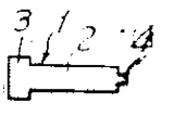
제1도 및 제2도는 표준적인 전자철심의 평면도.1 and 2 are plan views of standard electroconductive cores.
제3도는 이와 같은 전자철심이 결합된 제어릴레이의 구조예를 표시한 부분단면도.3 is a partial cross-sectional view showing an example of the structure of a control relay coupled to such an iron core.
제4(a)도, 제4(b)도, 제4(c)도, 제4(d)도, 제4(e)도, 제4(f)도는 본 발명의 압조공정의 공정도.Fig. 4 (a), Fig. 4 (b), Fig. 4 (c), Fig. 4 (d), Fig. 4 (e) and Fig. 4 (f) are the process charts of the pressure making process of the present invention.
제5도는 본 발명의 플랜지형 전자철심의 제작법의 공정도.5 is a process chart of the manufacturing method of the flange-type electroconductive core of the present invention.
제6도, 제7도 및 제8도는 본 발명의 방법으로 제작된 제1도 및 제2도에 표시한 전자철심의 금속조직의 현미경사진(배율 120).6, 7 and 8 are micrographs (magnification 120) of the metal structure of the electron iron core shown in FIGS. 1 and 2 produced by the method of the present invention.
제9도는 전자철심의 자화특성을 표시한 도표.9 is a chart showing the magnetization characteristics of the iron core.
본 발명은, 예를들면 전자릴레이, 전자개폐기등에 사용되는 고정 전자철심의 제작방법에 관한 것이다.The present invention relates to a method for manufacturing a fixed electronic core, for example, used in an electronic relay, an electronic switch, and the like.
전자릴레이는, 고정전자철심과 가동접극자로 되어 있으며, 권선이 여자되면 상호 접촉하므로서 개전되도록 한 구조를 가지고 있다. 대표적인 전자철심의 예를 제1도 및 제2도에 표시한다. 이와 같은 고정전자철심을 제작하는 소재로서, 종래부터, 그 고정전자철심에 요구되는 특성에 따라서, 소위 전자철심재(SU-YB) 내지는 저탄소강재가 사용되어 왔다. 실용적인 자기특성을 유지하기 위해서는, 소재는 일반적으로 탄소함유량이 0.005 중량% 이하, Mn이 5중량%이하, S가 0.03중량% 이하인 것이 경험적으로 알려져 있다. 이와 같은 저탄소의 연철재의 대표적인 전자철심재(SUYB)는, 철 이외에 약 0.005 중량% 정도의 탄소, 그리고 약 0.43 중량% 정도의 규소, 망간, 인, 유황 등의 불순물을 함유한다.The electronic relay has a fixed electromagnetic core and a movable contact pole, and has a structure in which the windings are opened by contacting each other when they are excited. Examples of typical electrocores are shown in FIGS. 1 and 2. As a material for producing such a fixed electronic core, so-called electron-core core (SU-YB) or a low carbon steel has been used according to the characteristics required for the fixed electronic core in the past. In order to maintain practical magnetic properties, it is known empirically that the material generally has a carbon content of 0.005% by weight or less, Mn of 5% by weight or less, and S of 0.03% by weight or less. The representative low-carbon soft iron core material (SUYB) contains, in addition to iron, about 0.005% by weight of carbon and about 0.43% by weight of impurities such as silicon, manganese, phosphorus, and sulfur.
종래, 전자철심은, 일반적으로, 열간압연된 전술한 소재를 그 소선직경으로부터 소정의 직경으로의 신선공정, 풀림공정, 이어서 철심의 두부 및 보스부분을 형성하기 위한 압조공정, 그 위에 자기특성을 높이기 위한 자기풀림공정, 그리고 최후에 표면처리공정(예를들면 도금, 니켈도금)을 거쳐서 제작되고 있다.Background Art Conventionally, an electroconductive core generally includes a hot rolling process of the above-described hot rolled material from its wire diameter to a predetermined diameter, followed by an unwinding process, followed by a pressing process for forming the head and boss portions of the iron core, and magnetic properties thereon. It is manufactured through a magnetic annealing process to increase the height and finally a surface treatment process (eg plating, nickel plating).
특히, 저탄소의 전자연철재를 사용하였을 경우에는, 실용적 자기 통성을 얻기위해서는 5회 또는 그 이상의 풀림공정을 반복하지 않으면 안되고, 따라서 전자철심의 생산비가 높아지는 결점이 있다. 이와 같은 자기풀림공정을 생략하기 위해서는, 냉간인발시의 풀림처리에 있어서 변형의 제거가 필요하게 된다. 그러나, 이 변형제거는, 전자특성의 저하외에, 페라이트 결정입자의 굵어짐을 초래하여, 이것이 압조성의 저하와 도금성의 저하에 결부되기 때문에 변형제거 공정의 실시는 곤란하게 된다.In particular, in the case of using a low carbon electro-soft iron material, in order to obtain practical magnetic permeability, five or more annealing steps must be repeated, and therefore, there is a drawback that the production cost of the electro-iron core becomes high. In order to omit such a self-releasing step, it is necessary to remove the deformation in the annealing treatment during cold drawing. However, this strain removal causes a thickening of the ferrite crystal grains in addition to the decrease in the electronic characteristics, and this leads to a decrease in the pressure-forming property and a decrease in the plating property, so that the strain removal process is difficult to perform.
한편, 저탄소강재는, 저생산가의 재료이고 또한 냉간신선공정을 단축하는 것이나, 그러나 자기특성을 유지하기 위해서는 풀림공정에서의 탈탄처리가 필요하게된다.On the other hand, a low carbon steel material is a material of low production cost and shortens a cold drawing process, but in order to maintain a magnetic characteristic, the decarburization process in an annealing process is needed.
따라서, 본 발명의 목적은 상기와 같은 결점을 개선하는 전자철심의 개량 제작방법을 제공하는 것이다.Accordingly, it is an object of the present invention to provide an improved manufacturing method of an iron core which improves the above drawbacks.
다른 목적은, 신규한 소재의 사용으로 제조생산가가 대폭 경감되는 전자철심의 개량 제작방법을 제공하는 것이다.Another object is to provide an improved manufacturing method for an electroconductive core, in which manufacturing production costs are greatly reduced by the use of new materials.
여기서, 전자철심을 제작함에 있어서, 전자철심재 또는 저탄소강재 대신에, 이것보다도 탄소함유량이 많고(0.01 중량% 정도 또는 그 이하)또는 불순물이 적은(0.31중량% 이하) 저생산가의 재료인 극연강을 사용하므로서, 신선공정의 대폭단축과 풀림공정(자기풀림)의 생략이 가능하게 되며, 따라서 제조생산가의 대폭적인 개선을 도모할 수 있다는 것이 발견되었다. 또, 이와 같은 극연강을 소재로해서, 소정의 조작공정을 행하므로서, 종래의 전자연철재로 제작된 전자철심에 뒤지지 않는 우수한 자기특성을 가진 전자철심을 제작할 수 있다는 것이 발견되었다.Here, in the production of the electro-iron core, instead of the electro-iron core or low carbon steel, ultra-soft steel which is a material having a higher carbon content (about 0.01 wt% or less) or less impurities (0.31 wt% or less) than this By using, it has been found that the drastic reduction of the drawing process and the elimination of the annealing process (magnetic annealing) can be made, and thus the production and production price can be greatly improved. Further, it has been found that an electric iron core having excellent magnetic properties comparable to that of a conventional iron core made of a conventional electro-soft iron material can be produced by performing a predetermined operation step using such ultra-soft steel as a material.
본 발명의 전자철심의 제작방법은, 극연강 소재를 소정의 가공도로 냉간 신선하고, 이 신선을 풀림처리에 붙여, 풀림이 신선을 소정의 가공도로 마무리신선해서 되는 것으로서, 이 마무리신선(전자철심)을 소망하는 형상으로 압조하고, 그리고 필요하면 표면처리하므로서 소망하는 형상의 전자철심으로 성형된다.The manufacturing method of the electroconductive core of this invention cold-dries a pole mild steel raw material to a predetermined process, and attaches this wire to an annealing process, and when an annealing finishes and draws a fresh wire to a predetermined process, this finishing wire (electro-core) ) Is pressed into a desired shape and, if necessary, surface-treated to form an electroconductive core of a desired shape.
본 발명의 제작방법에 사용되는 소재는, 탄소함유량이 0.01%중량%정도 또는 그 이하이며, 그리고 탄소를 제외한 불순물 함량이 0.31중량% 정도 또는 그 이하인 극연강이다. 이것은, 열간인발된 소선인 것이 바람직하다.The raw material used in the manufacturing method of this invention is carbon steel with a carbon content of about 0.01% by weight or less, and an impurity content except carbon about 0.31% by weight or less. It is preferable that this is hot drawn wire.
본 발명의 방법에 있어서의 냉간신선공정은, 열간인발된 극연강 소선을 20%이상, 바람직하게는 40%이상의 가공도로 냉간신선하므로서 달성된다. 이 냉간신선은, 그 후의 공정에 있어서의 가열처리조건에 라영향을 받지않는 균일한 페라이트입도를 얻는데에 필수적인 조건이 된다.The cold drawing process in the method of the present invention is accomplished by cold drawing hot drawn steel wire drawn to a workability of 20% or more, preferably 40% or more. This cold drawing becomes an essential condition for obtaining a uniform ferrite grain size which is not affected by the heat treatment conditions in subsequent steps.
냉간신선된 신냉은, 이어서 풀림처리에 붙어진다. 풀림은, 600~700℃로 3~8시간 가열하고, 이어서 550~650℃에서 공냉하므로서 행하여진다. 특히 바람직한 풀림조건은, 650℃로 5시간 가열하고, 600℃까지 17℃/시간씩 3시간 걸려서 냉각하고, 이어서 600℃에서 공냉하므로서 이루어진다. 이 풀림은 냉간신선공정에서 받은 변형을 제거해서 자벽(磁壁)의 이동을 용이하게 하기위해서 행하여지는 처리이다.The cold fresh fresh cold is then stuck to the annealing treatment. Annealing is performed by heating at 600-700 degreeC for 3 to 8 hours, and then air-cooling at 550-650 degreeC. Particularly preferable annealing conditions are achieved by heating at 650 ° C. for 5 hours, cooling to 600 ° C. over 3 hours at 17 ° C./hour, and then air cooling at 600 ° C. This annealing is a process performed to remove the deformation | transformation received in the cold drawing process, and to facilitate the movement of a magnetic wall.
이 변형제거풀림에 이어서 마무리신선이 행하여진다. 이 마무리 신선은 잔류변형을 적게하기 위해서 필요한 것이며, 10%이하, 바람직하게는 8%이하의 가공도로 행하여진다. 10%보다도 높은 높은 가공도로는 변형이 크고, 전자특성이 저하한다.Following this strain removal loosening, finishing drawing is performed. This finishing drawing is necessary to reduce residual strain, and is performed with a workability of 10% or less, preferably 8% or less. The higher the workability higher than 10%, the deformation is large and the electronic properties are deteriorated.
이상과 같이 해서 성형된 전자철심은, 페라이트 결정입도번호가 8정도이며, 매우 안정된 전자특성을 나타낸다. 이것은, 종래의 전자철심재 대신에 극연강을 사용하면 종래방법에서의 자기풀림공정을 실시하지 않아도, 종래 방법의 전자철심의 특성에 필적하고, 또는 그 이상 뛰어난 특성을 갖는 전자철심을 제작할 수 있다는 것을 나타내고 있다. 또, 본 발명의 방법에 의하면, 신선공정의 대폭적인 단축 및 풀림(자기풀림) 공정의 생략으로 대폭적인 제조생산가의 개선(40% 정도의 생산비 저하)을 도모할 수 있음The electroconductive core formed as described above has a ferrite grain size number of about 8 and exhibits very stable electronic characteristics. This means that by using ultra-soft steel instead of the conventional iron core material, it is possible to produce an electromagnetic iron core having characteristics superior to or superior to those of the conventional iron core without the magnetic loosening step of the conventional method. It is shown. In addition, according to the method of the present invention, it is possible to drastically shorten the drawing process and eliminate the unwinding (self-unwinding) process, thereby achieving a significant improvement in the production cost (a reduction in production cost of about 40%).
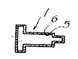
전술한 본 발명에 관한 전자철심은 통상, 압조 가공하므로서, 예를들면 제1도 및 제2도에 표시함과 같은 소망하는 형상의 전자철심으로 제작된다. 제1도 및 제2도는 직류 24V용 플랜지형 전자철심이다. 제1도에 있어서, (1)은 플랜지형 전자철심을 나타내고, (2)는 축부분을 나타낸다. 이 축부분(2)의 일단에는 플랜지 형상의 두부(3)가 형성되고, 또한 타단에는 보스부(4)가 형성되어 있다. 제2도는 제1도의 전자철심에 구리도금(5) 및 니켈도금(6)이 처리된 것이다. 이와 같은 플랜지형 전자철심(1)은 예를 들면 자동판매기 등의 제어릴레이용 고정전자철심으로서 사용된다.The electroconductive core according to the present invention described above is usually made of an electroconductive core having a desired shape, for example, as shown in FIGS. 1 and 2 are flanged electroconductive cores for direct current 24V. In FIG. 1, (1) shows a flange type electroconductive core, and (2) shows a shaft part. A flange-
제3도는 그 제어릴레이 구조의 일례를 표시한 부분단면도이다. 제어릴레이는 제3도에서 명백한 바와 같이 고정전자철심(10)과 가동접극자(11)를 포함하고, 권선(12)이 여자되면 상호 접촉하므로서 계전되도록한 구조를 가지고 있다. 또한, 제3도에 있어서, (13)은 베이스, (14)는 고정접촉판, (15)는 고정접점, (16)은 단자판, (17)은 요오크, (18)은 가동접점,(19)는 스프링,(20)는 연속선,(21)은 커버이다. 이와같은 제3도에 있어서 고정전자철심(10)은 제1도 내지는 제2도와 같은 플랜지형 전자철심(1)이 사용된다. 그 이유는 플랜지 형상의 두부(3)에 있어서 가동접극자(11)와의 접촉면적을 크게하고, 또 보스부(4)에 있어서 요오크(17)에서 부착을 용이하기 위한 것이다.3 is a partial sectional view showing an example of the control relay structure. The control relay includes a fixed
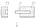
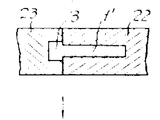
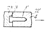
이와 같은 제1도 및 제2도에 표시한 전자철심을 본 발명의 방법에 의해 제작할 경우에는, 상기와 같이해서 얻어진 마무리신선을 소망하는 길이로 절단한 후, 압조해서 이것에 플랜지 형상 두부 밍 보스를 형성한다. 압조는 예를들면 제4(a)도, 제4(b)도, 제4(c)도, 제4(d)도, 제4(e)도, 제4(f)도에 표시함과 같은 공정에 의해서 행한다. 제4도의(1')에 있어서(1')는 소망하는 길이로 절단된 마무리신선이다. 이 마무리신선(1')을 다이 (22)속에 삽입하여, 펀치(23)로 마무리신선(1')의 일단을 압압해서 플랜지 형상 두부(3)를 형성한다. (제4(b)도 및 제4(c)도). 이에서 제4(d)도에 표시함과 같이 플랜지 형상 두부(3)의 부분을 펀치(23)에 물려서 마무리신선(1')을 다이(22)에서 꺼내고, 이것을 다른 다이(22')에 삽입해서 압압한다. 제4(d)도. 이와 같이 해서 압조된 마무리신선(1')을 다이(22')에서 꺼내서, 축부분(2)의 일단에 플랜지 형상 두부(3) 및 타단에 보스부(4)를 갖는 플랜지형 전자철심(1)을 얻는다. 제4(f)도.When manufacturing the electroconductive core shown in FIG. 1 and FIG. 2 by the method of this invention, after cutting the finishing wire obtained as mentioned above to desired length, it is pressed and flange-shaped head mincing boss to this. To form. For example, the pressure vessel is displayed on the fourth (a), fourth (b), fourth (c), fourth (d), fourth (e), and fourth (f) degrees. It is performed by the same process. (1 ') of FIG. 1 (1') is the finishing wire cut | disconnected to desired length. The finishing wire 1 'is inserted into the
이와 같이 해서 제작된 플랜지형 전자철심(1)은 플랜지 형상 두부(3) 및 보스부(4)에 재료의 흐름이 생겨서 이들 부분에서 전자특성이 저하되어도, 전체적으로는 이들 부분이 점유하는 비율은 근소(예를들면 플랜지 형상 두부의 길이 0.5mm, 축부분의 길이 14mm, 보스부의 길이 3mm)한 것이므로, 제품으로서의 플랜지형 전자철심의 전자특성은 플랜지 형상 두부 및 보스부에 있어서의 전자특성의 저하에 영향을 받는 일은 없다.In the flange-shaped electroconductive core 1 thus manufactured, even though materials flow in the flange-
또한, 제1도 및 제2도와 같은 직류 24V용의 플랜지형 전자철심의 제작에 있어서는, 마무리신선(1')을 0.5%이하의 가공도로 압조하고, 두부(3) 및 보스부(4)를 형성한다. 이 이상의 가공도로는, 축부분에 변형을 일으이게하여, 전자특성에 영향을 주게되므로 바람직하지 못하다.In addition, in the manufacture of a flange-type electromagnetic iron core for direct current 24V as shown in FIGS. 1 and 2, the finishing wire 1 'is pressed with a workability of 0.5% or less, and the
전술한 형상으로 압조된 플랜지형 전자철심은, 필요에 따라서 표면처리된다. 이 종류의 처리로서는, 통상, 구리도금, 이어서 니켈도금이 처리된다.The flange-type electroconductive core pressed into the above-mentioned shape is surface-treated as needed. As this kind of treatment, copper plating is usually followed by nickel plating.
본 발명을 예시하기 위해서 다음에 실시예를 설명한다.In order to illustrate the invention, the following examples are described.
[실시예]EXAMPLE
제1도 및 제2도에 표시함과 같은 직류 24V용 플랜지형 전자철심의 제작을 예시한다. 이 플랜지형 전자철심(1)은, 축부분(2), 두부(3), 보스부(4)로 되어 있으며, 그 표층부에는 구리도금(5) 및 니켈도금(6)이 처리되어 있다.The fabrication of a flanged electromagnetic iron core for direct current 24V as shown in FIGS. 1 and 2 is illustrated. This flange-shaped electroconductive core 1 is comprised of the shaft part 2, the
제5도에 표시함과 같이, 극연소강소선(ψ7)(101)을 48%의 가공도로 냉간신선(102)하고, 이어서 풀림처리(650℃로 5시간 가열후 3시간으로 600℃까지 냉각하고, 이어서 600℃로 공냉)(103)에 붙였다. 이어서 8%의 가공도로 마무리신선(104)을 행하였다. 이 마무리신선을 0.5%의 가공도로 압조가공(105)해서 두부와 보스부를 형성시켰다. 이어서, 형성된 철심에 표면처리(106)(5μ의 구리도금, 6μ의 니켈도금)을 해서, 제품을 얻었다.As shown in FIG. 5, the ultra-burning steel wire (ψ7) 101 is cold drawn at a processing rate of 48% (102), followed by annealing (heating at 650 ° C for 5 hours and cooling to 600 ° C for 3 hours. And then air-cooled at 600 ° C.). Subsequently, finish drawing 104 was performed at a workability of 8%. The finishing wire was pressed by a 0.5% workability to form a head and a boss. Subsequently, the formed iron core was subjected to surface treatment 106 (5 µ copper plating, 6 µ nickel plating) to obtain a product.
다음의 제1표에 소재의 종류, 화학성분, 냉간신선가공도, 제작된 전자철심의 특성을 요약한다. 또, 비교를 위해서, 전자철심재(SVYB)로 부터 종래의 방법에 의해 제조된 플랜지형 전자철심의 특성도 표시한다.The following table summarizes the type of material, chemical composition, cold drawing and the characteristics of the fabricated core. In addition, for the purpose of comparison, the characteristics of the flange-shaped electroconductive core manufactured by the conventional method from the electroconductive core material SVYB are also shown.
[제 1 표][Table 1]

본 발명의 전자철심 제작방법을 사용해서 성형된 제품에 의한 두부 (3), 축부분(2) 및 보스부(4)의 금속조직의 현미경사진(배율 120)을 각각 제6도, 제7도 및 제8도에 표시한다. 두부 및 보스부에는 재료의 흐름이 확인되었다, (제6도 및 제8도) 축부분(2)에는 소성 변형이 적은 균일한 페라이트입자(입도번호6)의 존재가 확인되었다.6 and 7 of the micrographs (magnification 120) of metal structures of the
(제7도)(Fig. 7)
또, 상기와 같이 제작된 전자철심 A및 B와 종래법의 전자철심(SVYB)의 자화시험을 행하였다. 시험은, 시판하는 직류자화측정장치로 행하였다. 결과를 제9도에 표시한다. 본 발명의 전자철심 A는, SVYB로 부터의 철심에 상당하는 자화력을 가지고 있음을 알 수 있다. 또, 냉간신선의 가공도가 작은 철심 B는 자화력이 작다.Moreover, the magnetization test of the electroconductive core A and B produced as mentioned above, and the electroconductive core (SVYB) of the conventional method was done. The test was carried out with a commercially available direct current magnetometer. The results are shown in FIG. It turns out that the electroconductive core A of this invention has the magnetization power corresponded to the iron core from SVYB. In addition, iron core B, which has a low degree of cold drawing, has a small magnetization force.
Claims (1)
Priority Applications (1)
| Application Number | Priority Date | Filing Date | Title |
|---|---|---|---|
| KR1019800003210A KR830001552B1 (en) | 1980-08-14 | 1980-08-14 | Manufacturing method of electronic iron core |
Applications Claiming Priority (1)
| Application Number | Priority Date | Filing Date | Title |
|---|---|---|---|
| KR1019800003210A KR830001552B1 (en) | 1980-08-14 | 1980-08-14 | Manufacturing method of electronic iron core |
Publications (2)
| Publication Number | Publication Date |
|---|---|
| KR830003789A KR830003789A (en) | 1983-06-22 |
| KR830001552B1 true KR830001552B1 (en) | 1983-08-10 |
Family
ID=19217422
Family Applications (1)
| Application Number | Title | Priority Date | Filing Date |
|---|---|---|---|
| KR1019800003210A Expired KR830001552B1 (en) | 1980-08-14 | 1980-08-14 | Manufacturing method of electronic iron core |
Country Status (1)
| Country | Link |
|---|---|
| KR (1) | KR830001552B1 (en) |
-
1980
- 1980-08-14 KR KR1019800003210A patent/KR830001552B1/en not_active Expired
Also Published As
| Publication number | Publication date |
|---|---|
| KR830003789A (en) | 1983-06-22 |
Similar Documents
| Publication | Publication Date | Title |
|---|---|---|
| EP2458601B1 (en) | Soft magnetic powdered core and method for producing same | |
| EP1026267A1 (en) | Method for producing high silicon steel, and silicon steel | |
| CN107689280A (en) | Powder core, molding inductance and its manufacture method | |
| US3948690A (en) | Molded magnetic cores utilizing cut steel particles | |
| US2241441A (en) | Manufacture of magnetic bodies | |
| US1669644A (en) | Magnetic material | |
| US10010935B2 (en) | Iron powder for dust cores | |
| CN107424711B (en) | Iron-based composite powder for manufacturing magnetic powder core and die-pressed inductor and preparation method thereof | |
| KR830001552B1 (en) | Manufacturing method of electronic iron core | |
| US1647737A (en) | Magnetic core | |
| KR100396045B1 (en) | Silicon steel powder processing method for soft magnetic core material and soft magnetic core processing method using this powder | |
| JPS63117406A (en) | Amorphous alloy dust core | |
| JP2005116820A (en) | Dust core | |
| US4369077A (en) | Method of manufacturing an electromagnetic core | |
| US1809042A (en) | Magnet core | |
| CA1196552A (en) | Making a mold for continuous casting | |
| JPS5953683B2 (en) | Manufacturing method of electromagnetic core | |
| US1669665A (en) | Magnetic material | |
| JPH11236618A (en) | Manufacturing method of non-oriented electrical steel sheet with low iron loss | |
| US1818070A (en) | Magnetic body | |
| US1669643A (en) | Magnetic material | |
| US1669649A (en) | Magnetic material | |
| US2937964A (en) | Magnetic flake core | |
| US1739068A (en) | Method of producing materials in finely-divided form | |
| JPH0742559B2 (en) | Amorphous alloy ribbon for magnetic core with excellent space factor and method for producing the same |
Legal Events
| Date | Code | Title | Description |
|---|---|---|---|
| PA0109 | Patent application |
Patent event code: PA01091R01D Comment text: Patent Application Patent event date: 19800814 |
|
| PE0902 | Notice of grounds for rejection |
Comment text: Notification of reason for refusal Patent event date: 19830330 Patent event code: PE09021S01D |
|
| PG1501 | Laying open of application | ||
| PG1605 | Publication of application before grant of patent |
Comment text: Decision on Publication of Application Patent event code: PG16051S01I Patent event date: 19830707 |
|
| PE0701 | Decision of registration |
Patent event code: PE07011S01D Comment text: Decision to Grant Registration Patent event date: 19831018 |
|
| PR0701 | Registration of establishment |
Comment text: Registration of Establishment Patent event date: 19831021 Patent event code: PR07011E01D |
|
| PR1002 | Payment of registration fee |
Payment date: 19831021 End annual number: 3 Start annual number: 1 |
|
| PR1001 | Payment of annual fee |
Payment date: 19860625 Start annual number: 4 End annual number: 4 |
|
| PR1001 | Payment of annual fee |
Payment date: 19870706 Start annual number: 5 End annual number: 5 |
|
| PR1001 | Payment of annual fee |
Payment date: 19880209 Start annual number: 6 End annual number: 7 |
|
| PR1001 | Payment of annual fee |
Payment date: 19900807 Start annual number: 8 End annual number: 8 |
|
| PR1001 | Payment of annual fee |
Payment date: 19910807 Start annual number: 9 End annual number: 9 |
|
| PR1001 | Payment of annual fee |
Payment date: 19920729 Start annual number: 10 End annual number: 10 |
|
| PR1001 | Payment of annual fee |
Payment date: 19930804 Start annual number: 11 End annual number: 11 |
|
| PR1001 | Payment of annual fee |
Payment date: 19940806 Start annual number: 12 End annual number: 12 |
|
| PC1801 | Expiration of term |