KR20250017841A - Manhole Fall Prevention Structure - Google Patents
Manhole Fall Prevention Structure Download PDFInfo
- Publication number
- KR20250017841A KR20250017841A KR1020230098755A KR20230098755A KR20250017841A KR 20250017841 A KR20250017841 A KR 20250017841A KR 1020230098755 A KR1020230098755 A KR 1020230098755A KR 20230098755 A KR20230098755 A KR 20230098755A KR 20250017841 A KR20250017841 A KR 20250017841A
- Authority
- KR
- South Korea
- Prior art keywords
- manhole
- fall prevention
- nut cap
- frame
- prevention structure
- Prior art date
- Legal status (The legal status is an assumption and is not a legal conclusion. Google has not performed a legal analysis and makes no representation as to the accuracy of the status listed.)
- Granted
Links
Images





Classifications
-
- E—FIXED CONSTRUCTIONS
- E02—HYDRAULIC ENGINEERING; FOUNDATIONS; SOIL SHIFTING
- E02D—FOUNDATIONS; EXCAVATIONS; EMBANKMENTS; UNDERGROUND OR UNDERWATER STRUCTURES
- E02D29/00—Independent underground or underwater structures; Retaining walls
- E02D29/12—Manhole shafts; Other inspection or access chambers; Accessories therefor
- E02D29/127—Manhole shafts; Other inspection or access chambers; Accessories therefor with devices for impeding fall or injuries of persons
-
- E—FIXED CONSTRUCTIONS
- E02—HYDRAULIC ENGINEERING; FOUNDATIONS; SOIL SHIFTING
- E02D—FOUNDATIONS; EXCAVATIONS; EMBANKMENTS; UNDERGROUND OR UNDERWATER STRUCTURES
- E02D29/00—Independent underground or underwater structures; Retaining walls
- E02D29/12—Manhole shafts; Other inspection or access chambers; Accessories therefor
- E02D29/14—Covers for manholes or the like; Frames for covers
-
- E—FIXED CONSTRUCTIONS
- E02—HYDRAULIC ENGINEERING; FOUNDATIONS; SOIL SHIFTING
- E02D—FOUNDATIONS; EXCAVATIONS; EMBANKMENTS; UNDERGROUND OR UNDERWATER STRUCTURES
- E02D2200/00—Geometrical or physical properties
- E02D2200/11—Height being adjustable
-
- E—FIXED CONSTRUCTIONS
- E02—HYDRAULIC ENGINEERING; FOUNDATIONS; SOIL SHIFTING
- E02D—FOUNDATIONS; EXCAVATIONS; EMBANKMENTS; UNDERGROUND OR UNDERWATER STRUCTURES
- E02D2200/00—Geometrical or physical properties
- E02D2200/16—Shapes
- E02D2200/1607—Shapes round, e.g. circle
Landscapes
- Engineering & Computer Science (AREA)
- Environmental & Geological Engineering (AREA)
- Life Sciences & Earth Sciences (AREA)
- General Life Sciences & Earth Sciences (AREA)
- Mining & Mineral Resources (AREA)
- Paleontology (AREA)
- Civil Engineering (AREA)
- General Engineering & Computer Science (AREA)
- Structural Engineering (AREA)
- Underground Structures, Protecting, Testing And Restoring Foundations (AREA)
Abstract
Description
본 발명은 맨홀 추락방지구조에 관한 것으로서, 좀더 상세하게는 원형 맨홀 내부에 구비되어 맨홀 내부관리 작업시 또는 집중강우로 인해 역류압에 의한 맨홀뚜껑 개방과 주변 침수로 인한 보행자의 추락 및 물과 함께 맨홀 내부로 보행자가 빨려 들어 가는 인명사고를 방지할 수 있도록 맨홀 내에 추락방지구를 더욱 견고하게 제공함은 물론, 추락방지구를 완전히 제거하지 않은 상태에서 맨홀 내부로 맨홀 내부의 청소 및 막힘 해결을 위한 특수장비의 투입이 이루어질 수 있도록 한 맨홀 추락방지구조에 관한 것이다.The present invention relates to a manhole fall prevention structure, and more specifically, to a manhole fall prevention structure which provides a fall prevention device more firmly inside a manhole to prevent accidents involving pedestrians falling or being sucked into the manhole together with water due to the opening of the manhole cover and surrounding flooding caused by backflow pressure during manhole internal management work or due to heavy rain, and which allows special equipment for cleaning the inside of the manhole and resolving blockages to be introduced into the manhole without completely removing the fall prevention device.
일반적으로 맨홀(manhole)이란, 노면(路面)에서 지하로 사람이 출입할 수 있게 만든 구멍으로, 용도에 따라 상.하수도용, 우수용, 오수용, 및 전기통신용으로 구분되며 도로에 일정간격마다 설치되어 있다.In general, a manhole is a hole made from the road surface to allow people to enter and exit underground. Depending on the purpose, it is classified as for water supply and sewage, rainwater, wastewater, and telecommunications, and is installed at regular intervals on the road.
급속한 도시화로 인해 아스팔트 및 시멘트로 덮인 도시는 배수시스템의 건설을 중요하게 여기지 않았다.Due to rapid urbanization, cities covered with asphalt and cement did not attach importance to the construction of drainage systems.
그러나, 최근 들어 이상기후로 인한 집중강우가 자주 발생하여 종종 홍수가 발생하고 있으며 그로 인한 피해가 점차 심각해 지고 있다. However, recently, due to abnormal climate, heavy rainfall has occurred frequently, causing frequent flooding and the resulting damage is becoming increasingly serious.
따라서, 도심지의 침수를 방지하기 위해 우수관거 시스템의 우수배수능력 증가는 필수적인 요소이다. Therefore, increasing the drainage capacity of the rainwater drainage system is an essential element to prevent flooding in urban areas.
우수관거 시설은 관거, 맨홀, 우수토실, 물받이 및 연결관 등을 포함하는 시설들로 구성되어 있다. The rainwater drainage system consists of facilities such as pipes, manholes, rainwater tanks, water receivers, and connecting pipes.
또한, 우수관거 시스템의 유지와 관리를 위한 출입구로서 일정거리마다 맨홀을 설치하고 있다. 이러한 맨홀은 관의 경사, 방향, 관경이 변하는 곳에 설치한다.In addition, manholes are installed at regular intervals as entrances and exits for maintenance and management of the sewer system. These manholes are installed in places where the slope, direction, and diameter of the pipe change.
따라서, 맨홀은 일반적으로 차도나 보도, 주택가 등 장소를 가리지 않고 흔히 볼 수 있지만 맨홀작업을 위해 맨홀 뚜껑을 오픈 하였을 때 미쳐 작업중임을 인지하지 못한 보행자가 하수도관에 떨어지는 낙상사고가 일어나 보행자가 크게 다칠 뿐만 아니라 하수도관에서 작업 중이던 작업자까지 다치는 위험이 있었다.Therefore, manholes are commonly seen in places such as roads, sidewalks, and residential areas, but when a manhole cover is opened for manhole work, pedestrians who are unaware of the work in progress may fall into sewer pipes, causing serious injuries to the pedestrians as well as the workers working on the sewer pipes.
또한, 집중강우로 인한 낮은 침수지역의 도관으로는 물이 역류하여 굳게 닫힌 맨홀 뚜껑을 강한 수압(역류압)으로 개방되는 사례가 발생하며, 역류된 물이 지상으로 차오른 상태가 발생하기 때문에 침수지역을 대피하는 과정에서 맨홀 도관 내부로 빨려들어가는 인명사고가 발생하기도 한다.In addition, in areas with low flooding due to heavy rainfall, water may flow back into the pipes, causing tightly closed manhole covers to open due to strong water pressure (backflow pressure). As the backflowed water rises to the ground, accidents may occur in which people are sucked into the manhole pipes during the process of evacuating the flooded area, resulting in fatalities.
상기와 같은 점을 감안한 선원기술을 살피면, 대한민국 등록특허 제10-0725352호(명칭: 맨홀뚜껑 이탈방지장치, 이하 이를 '특허문헌 1'이라 함) 및 공개특허 제10-2011-0025507호(명칭: 안전 맨홀구조체, 이하 이를 '특허문헌 2'라 함)이 개시되어 있다.Taking the above points into consideration, when examining the sailor's technology, Korean Patent No. 10-0725352 (Title: Manhole cover detachment prevention device, hereinafter referred to as 'Patent Document 1') and Publication Patent No. 10-2011-0025507 (Title: Safety manhole structure, hereinafter referred to as 'Patent Document 2') are disclosed.
상기 특허문헌 1은 차량바퀴의 충격이나 홍수 시 수압의 작용으로 맨홀 뚜껑이 이탈됨으로써 보행자나 차량 등이 맨홀로 추락하는 것을 방지하기 위한 것으로,The
맨홀의 상부에 설치되어 출입구를 형성하기 위한 맨홀 본체와 상기 맨홀 본체를 개폐하기 위한 맨홀 뚜껑과, 상기 맨홀 본체에 결합되어 맨홀 뚜껑을 지지하도록 하되 테두리의 안쪽 상부에는 원형의 뚜껑중심 받침판과 링을 구비하는 지지봉이 형성되도록 하고 테두리 상단과 뚜껑중심 받침판 상단, 링의 상단의 높이는 맨홀 본체의 안쪽에 형성된 걸림턱의 높이와 동일하게 형성함으로써 테두리 상단과 뚜껑중심 받침판 상단, 링의 상부면이 모두 맨홀 뚜껑의 저면에 밀착되도록 지지하기 위한 지지틀로 이루어지는 맨홀뚜껑 이탈방지장치에 있어서,A manhole cover detachment prevention device comprising a manhole body installed on the upper part of a manhole to form an entrance and exit, a manhole cover for opening and closing the manhole body, and a support bar coupled to the manhole body to support the manhole cover, wherein a circular lid center support plate and a ring are formed on the inner upper part of the rim, and the heights of the upper part of the rim, the upper part of the lid center support plate, and the upper part of the ring are formed to be the same as the height of a catch formed on the inner part of the manhole body, thereby supporting the upper part of the rim, the upper part of the lid center support plate, and the upper surface of the ring so that they are all in close contact with the lower surface of the manhole cover.
상기 본체는 뚜껑 안착부에 다수개의 통공이 형성되고, 상기 통공에는 볼트와 너트로 이루어지는 체결수단이 결합되도록 하며, 상기 지지틀은 가장자리에 판형상을 갖는 원형의 테두리로 이루어지도록 하고, 상기 테두리에는 체결수단과 대응되도록 "ㄱ"자 형상의 체결홈이 형성되도록 하되, 상기 체결수단이 체결홈에 끼워진 상태로 나사결합되어 지지틀을 고정하도록 구성된다.The above body is configured such that a plurality of holes are formed in the lid mounting portion, and a fastening means formed of bolts and nuts is coupled to the holes, and the support frame is configured such that a circular frame having a plate shape at the edge thereof is formed, and a fastening groove in the shape of the letter “ㄱ” is formed in the frame to correspond to the fastening means, and the fastening means is screwed in while being fitted into the fastening groove to fix the support frame.
즉, 지지틀을 맨홀 본체에 체결수단에 의해 견고하게 고정시킴으로써 맨홀 뚜껑의 열림을 최소화할 수 있고, 맨홀 뚜껑이 개방되었다 하더라도 보행자의 추락사고와 차량의 바퀴 빠짐 사고 등을 최소화시킬 수 있는 효과를 갖도록 하고 있다.That is, by firmly fixing the support frame to the manhole body by means of a fastening means, the opening of the manhole cover can be minimized, and even if the manhole cover is opened, it has the effect of minimizing accidents such as pedestrians falling and vehicles having wheels come off.
하지만, 상기 지지틀의 고정은 본체의 외측에서 관통 설치된 고정볼트 본체의 내측에서 상기 고정볼트와 체결되는 너트 사이에 지지틀에 마련한 "ㄱ"자 형상의 체결홈이 안내되어 고정되는 것이기에 맨홀 특성상 도로 진동, 역류압, 역류에 의한 협작물 걸림과 저항에 의한 풀림 현상으로 지지틀의 체결홈이 고정볼트로부터 벗어나 변형되거나 분리될 수 있기 때문에 애기치 못한 안전사고가 발생할 수 있다.However, since the fixing of the support frame is guided by a “L” shaped fastening groove provided in the support frame between a nut fastened to the fixing bolt installed through the outside of the main body and the fixing bolt on the inside of the main body, the fastening groove of the support frame may become deformed or separated from the fixing bolt due to road vibration, backflow pressure, and backflow-induced interference with the object, and loosening due to resistance, which is characteristic of manholes, and thus an unexpected safety accident may occur.
상기 특허문헌 2는 맨홀덮개가 맨홀본체의 관통홀에 삽입된 상태로 간편하고 용이하게 위치 고정될 수 있으며, 상·하수의 역류에 따른 이탈이 방지될 수 있도록 한 것으로, 상·하수구 유로관과 연결되는 슬래브의 상측에 설치되고, 중심부에는 상기 슬래브의 내부와 연통되는 원형의 관통홀이 형성되며, 상기 관통홀의 내주면을 따라 수직으로 복수의 장홈이 형성된 맨홀본체; 및 상기 관통홀에 대응되는 원형으로 구비되어 상기 관통홀에 내주면에 형성된 단(段)에 안착됨으로써 상기 관통홀의 상측을 덮어 폐쇄하며, 상기 복수의 장홈에 각각 삽입되어 상기 복수의 장홈과 연통되게 수평으로 형성된 안내홈을 따라 이송되는 복수의 돌출키가 외측면에 형성된 맨홀덮개;를 포함하되, 상기 맨홀덮개는, 상기 관통홀에 삽입된 후 회전되어 상기 복수의 돌출키가 상기 안내홈 내에 위치됨으로써, 상기 관통홀의 상측을 덮은 상태로 이탈이 방지되도록 구성한 것이다.The
또한, 맨홀 내부에는 추락방지를 위한 보조맨홀덮개를 나선형태로 체결한 것으로, 보조적으로 맨홀본체의 관통홀을 폐쇄시키는 역할을 하면서 보행자 또는 작업자가 관통홀로 실족하여 추락하는 등의 안전사고 발생을 방지할 수 있다.In addition, an auxiliary manhole cover is installed in a spiral shape inside the manhole to prevent falls, which serves to close the penetration hole of the manhole body and prevent safety accidents such as pedestrians or workers slipping and falling into the penetration hole.
하지만, 상기와 같은 보조맨홀덮개는 맨홀 내에서 나사방식으로 체결고정하고, 잠금 키에 의해 완벽한 고정이 이루어지지만, 이를 체결하는 작업 또는 분리하는 작업이 매우 번거로울 뿐만 아니라 오랜 방치로 인해 물 또는 습기에 의해 체결부위의 부식으로 개방이 어려워지는 문제점이 있으며, 가령 개방하더라도, 재 체결을 위해 나선 체결부위의 부식된 부분을 나사체결이 잘 이루어지도록 관리하여야 하는 문제점이 있다.However, although the auxiliary manhole cover as described above is fastened with screws inside the manhole and is perfectly fixed with a lock key, the work of fastening or detaching it is very cumbersome, and there is a problem that it becomes difficult to open due to corrosion of the fastening part caused by water or moisture if left unattended for a long time, and even if it is opened, there is a problem that the corroded part of the spiral fastening part must be managed so that the screw fastening is done well for re-fastening.
본 발명은 상기와 같이 제반되는 종래의 문제점을 해결하기 위하여 발명한 것으로서, 원형 맨홀 내부에 구비되어 맨홀 내부관리 작업시 또는 집중강우로 인해 역류압에 의한 맨홀뚜껑 개방과 주변 침수로 인한 보행자의 추락 및 물과 함께 맨홀 내부로 보행자가 빨려 들어 가는 인명사고를 방지할 수 있도록 맨홀 내에 추락방지구를 견고하게 제공함은 물론, 추락방지구를 완전히 제거하지 않은 상태에서 맨홀 내부로 맨홀 내부의 청소 및 막힘 해결을 위한 특수장비의 투입이 이루어질 수 있도록 한 맨홀 추락방지구조를 제공하는데 그 목적이 있다.The present invention has been made to solve the above-mentioned problems of the related art, and the purpose of the present invention is to provide a manhole fall prevention structure that firmly provides a fall prevention device inside a manhole to prevent accidents caused by pedestrians falling or being sucked into the manhole together with water due to the opening of the manhole cover and surrounding flooding caused by backflow pressure during manhole internal management work or due to heavy rain, and to enable special equipment for cleaning the inside of the manhole and resolving blockages to be introduced into the manhole without completely removing the fall prevention device.
상기 목적을 달성하기 위한 본 발명에 의하면, 상부에 맨홀뚜껑이 안착되는 맨홀프레임의 내측둘레 또는 맨홀프레임이 매입된 개구부의 내측벽에 추락방지구가 고정 설치되어 맨홀뚜껑이 개방된 맨홀 내부로의 추락을 방지하도록 된 맨홀 추락방지구조에 있어서,According to the present invention for achieving the above purpose, a manhole fall prevention structure is provided in which a fall prevention device is fixedly installed on the inner circumference of a manhole frame on which a manhole cover is installed on the upper portion or on the inner wall of an opening in which the manhole frame is embedded to prevent the manhole cover from falling into an open manhole.
상기 추락방지구는, 금속재로 된 원형틀과, 상기 원형틀의 외측둘레에 방사상으로 간격지게 부착되며, 그 끝단에는 수나사부가 형성된 환봉형의 지지대와, 원형의 링 형상으로 상기 원형틀에 대해 동심원상으로 용접 부착되어져 지지대들을 보강하는 보강링과, 상기 지지대의 수나사부에 체결되는 너트캡과, 십자형태로 형성되어 상기 원형틀에 탈착되게 설치되는 크로스바를 포함하는 구성으로 이루어져 지지대의 수나사부측에 체결된 너트캡의 풀림에 의해 너트캡의 끝단이 맨홀 내측벽에 각각 밀착 가압되게 고정 설치되는 것을 특징으로 한다.The above-mentioned fall prevention device comprises a circular frame made of metal, a round bar-shaped support member that is radially spaced apart from the outer periphery of the circular frame and has a male screw portion formed at the end thereof, a reinforcing ring that is welded concentrically to the circular frame in the shape of a circular ring to reinforce the support members, a nut cap that is fastened to the male screw portion of the support member, and a cross bar that is formed in a cross shape and is detachably installed to the circular frame, and is characterized in that the ends of the nut caps are fixedly installed so as to be pressed against the inner wall of the manhole by loosening the nut cap that is fastened to the male screw portion of the support member.
본 발명에 따른 상기 원형틀은 내주면에 레일홈을 갖는 'ㄷ'자형의 단면으로 형성되되, 상부에는 상기 레일홈과 통하며, 크로스바의 일단을 각각 안내하는 삽입홈부가 형성되고, 레임홈 내에는 크로스바를 레일홈으로부터 회전시 크로스바를 정지시키는 스톱퍼가 형성된 것을 특징으로 한다.The above-described circular frame according to the present invention is formed with a cross-section in the shape of the letter 'ㄷ' having a rail groove on the inner surface, and is characterized in that an insertion groove portion is formed on the upper portion thereof, which communicates with the rail groove and guides one end of each crossbar, and a stopper is formed within the frame groove to stop the crossbar when it rotates from the rail groove.
본 발명에 따른상기 너트캡의 길이방향에는 구리스 주입홀이 형성된 것을 특징으로 한다.The nut cap according to the present invention is characterized in that a grease injection hole is formed in the longitudinal direction.
본 발명에 따른 상기 너트캡이 밀착 가압되는 맨홀의 개구된 내측벽에는 금속소재로서 상기 내측벽과 동일한 내직경을 갖되, 내직경에는 상기 너트캡의 일단이 수용되어 지지되는 안내홈부가 배열된 링형의 지지부재가 매입 설치된 것을 특징으로 한다.According to the present invention, the nut cap is pressed tightly into the opened inner wall of the manhole, and is characterized in that a ring-shaped support member is installed therein, made of a metal material and having the same inner diameter as the inner wall, but having a guide groove arranged on the inner diameter to receive and support one end of the nut cap.
본 발명에 따른 상기 너트캡이 밀착 가압되는 맨홀의 개구된 내측벽에는 너트캡의 일단이 수용되어 지지되는 요홈이 형성된 것을 특징으로 한다.According to the present invention, the nut cap is characterized in that a groove is formed in the opened inner wall of the manhole to be pressed tightly, in which one end of the nut cap is received and supported.
본 발명에 따른 맨홀 추락방지구조는, 원형틀로부터 방사상으로 배치된 지지대 및 지지대에 부착된 보강링의 부착으로 맨홀 내부의 내측벽, 맨홀프레임의 내부직경의 통로를 차단하면서 각 지지대의 단부측에 마련된 수나사부에 너트캡이 체결된 추락방지구를 제공하되, 수나사부로부터 너트캡을 풀어 지지대로부터 너트캡의 일단부가 맨홀 내부의 내측벽, 맨홀프레임의 내부직경에 밀착 가압되게 하거나, 내측벽에 마련된 요홈 또는 내측벽에 매입된 별도의 지지부재측 안내홈부에 너트캡이 안내되어 밀착 가압으로 고정되게 함으로써, 맨홀 내부로부터 추락방지구를 보다 견고하게 고정할 수 있다. 이는 홍수에 의한 역류압으로 맨홀뚜껑이 맨홀프레임에서 이탈되더라도 맨홀 내부로 보행자의 추락을 방지시켜 안전사고를 예방할 수 있으며, 맨홀로부터 추락방지구의 해제시에는 반대로 일부의 너트캡을 수나사부에 체결하는 간단한 방식으로 분리할 수 있어 맨홀로부터 탈부착을 용이하다.The manhole fall prevention structure according to the present invention provides a fall prevention device in which a nut cap is fastened to a male screw portion provided at an end side of each support while blocking a passage of an inner wall inside a manhole and an inner diameter of a manhole frame by attaching supports radially arranged from a circular frame and reinforcing rings attached to the supports, and the nut cap is released from the male screw portion so that one end of the nut cap is pressed against the inner wall inside the manhole and the inner diameter of the manhole frame, or the nut cap is guided to a groove provided on the inner wall or a separate support member-side guide groove embedded in the inner wall and fixed by pressurization, thereby enabling the fall prevention device to be more firmly fixed from the inside of the manhole. This prevents safety accidents by preventing pedestrians from falling into the manhole even if the manhole cover is detached from the manhole frame due to backflow pressure caused by flooding. In addition, when the fall prevention device is released from the manhole, it can be easily detached by simply attaching a part of the nut cap to the male screw portion in the opposite direction.
또한, 원형틀에 탈착가능하게 설치되는 크로스바는 추락방지구를 맨홀로부터 분리하지 않고도 크로스바만을 간단히 분리하여 맨홀 내부 청소 나 막힌해결을 위해 특수장비의 진출이 가능한 용도로서 이용할 수 있기 때문에 상기와 같이, 추락방지와 더불어 맨홀 내부관리를 유용하게 수행할 수 있는 이점이 제공된다.In addition, the crossbar detachably installed on the circular frame can be used for the purpose of allowing special equipment to enter the manhole for cleaning the inside of the manhole or clearing a blockage by simply detaching only the crossbar without detaching the fall prevention device from the manhole, so that, as described above, it provides the advantage of being able to usefully perform manhole interior management in addition to fall prevention.
도 1은 본 발명의 맨홀 추락방지구를 맨홀에 적용된 상태를 예시한 사시도,
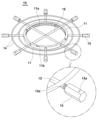
도 2는 본 발명에 따른 추락방지구를 발췌하여 도시한 사시도,
도 3은 본 발명에 따른 추락방지구의 원형틀로부터 크로스바를 분리한 상태를 보여주는 사시도,
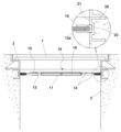
도 4는 본 발명에 따른 추락방지구를 맨홀 내에 설치된 상태를 보여주는 횡단면도,
도 5는 본 발명에 따른 추락방지구를 맨홀프레임 내측둘레에 설치된 상태를 도시한 단면도,
도 6은 본 발명에 따른 추락방지구의 지지대측 너트캡을 맨홀 내부의 내측벽에 마련된 요홈에 안내 설치된 상태를 도시한 일부분 확대 단면도,
도 7은 본 발명에 따른 맨홀 내부에 매입시킨 지지부재에 추락방지구가 설치된 상태를 보여주는 단면도,
도 8은 도 7에서 지지부재를 발췌하여 도시한 사시도,
도 9의 (a)(b)는 본 발명에 따른 지지대측의 너트캡의 고정상태를 보여주는 확대 단면도,
도 10은 본 발명에 따른 추락방지구의 구성 중 크로스바에 보조 보강링을 더 부착한 예를 보여주는 사시도이다.Figure 1 is a perspective view illustrating a state in which the manhole fall prevention device of the present invention is applied to a manhole.
Figure 2 is a perspective view illustrating an excerpt of a fall prevention device according to the present invention.
Figure 3 is a perspective view showing the crossbar separated from the circular frame of the fall prevention device according to the present invention.
Figure 4 is a cross-sectional view showing a state in which a fall prevention device according to the present invention is installed in a manhole.
Figure 5 is a cross-sectional view showing a state in which a fall prevention device according to the present invention is installed on the inner circumference of a manhole frame.
Figure 6 is a partially enlarged cross-sectional view showing a state in which a support-side nut cap of a fall prevention device according to the present invention is guided and installed in a groove provided on the inner wall inside a manhole.
Figure 7 is a cross-sectional view showing a state in which a fall prevention device is installed on a support member embedded in a manhole according to the present invention.
Fig. 8 is a perspective view showing the support member extracted from Fig. 7.
Figures 9 (a) and (b) are enlarged cross-sectional views showing the fixing state of the nut cap on the support side according to the present invention.
Figure 10 is a perspective view showing an example of a fall prevention device according to the present invention in which an auxiliary reinforcing ring is further attached to the crossbar.
이하, 본 발명을 첨부된 도면을 참조하여 더욱 상세하게 설명하면 다음과 같다.Hereinafter, the present invention will be described in more detail with reference to the attached drawings.
이에 앞서, 본 명세서 및 청구범위에 사용된 용어나 단어는 통상적이거나 사전적인 의미로 한정해서 해석되어서는 아니 되며, 발명자는 그 자신의 발명을 가장 최선의 방법으로 설명하기 위해 용어의 개념을 적절하게 정의할 수 있다는 원칙에 입각하여 본 발명의 기술적 사상에 부합하는 의미와 개념으로 해석되어야만 한다.Prior to this, terms or words used in this specification and claims should not be interpreted as limited to their usual or dictionary meanings, and should be interpreted as meanings and concepts that conform to the technical idea of the present invention based on the principle that the inventor can appropriately define the concept of the term in order to explain his or her own invention in the best way.
따라서, 본 명세서에 기재된 실시 예와 도면에 도시된 구성은 본 발명의 가장 바람직한 일 실시 예에 불과할 뿐이고, 본 발명의 기술적 사상을 모두 대변하는 것은 아니므로, 본 출원시점에 있어서 이들은 대체할 수 있는 다양한 균등물과 변형 예들이 있을 수 있음을 이해하여야 한다.Accordingly, the embodiments described in this specification and the configurations illustrated in the drawings are only the most preferred embodiments of the present invention and do not represent all of the technical ideas of the present invention. Therefore, it should be understood that there may be various equivalents and modified examples that can be replaced with them at the time of filing this application.
본 발명에 따른 추락방지구조는 첨부된 도 1 내지 도 10을 참조하여 설명하면 다음과 같다.The fall prevention structure according to the present invention is described as follows with reference to the attached
상부에 맨홀뚜껑(1)이 안착되는 맨홀프레임(2)의 내측둘레 또는 맨홀프레임(2)이 매입된 개구부의 내측벽(3)에 추락방지구(10)가 고정 설치되어 맨홀뚜껑이 개방된 맨홀 내부로의 추락을 방지하도록 된 맨홀용 추락방지구조에 있어서,In a fall prevention structure for a manhole, a fall prevention device (10) is fixedly installed on the inner circumference of a manhole frame (2) on which a manhole cover (1) is installed on the upper part or on the inner wall (3) of an opening in which the manhole frame (2) is embedded to prevent the manhole cover from falling into an open manhole.
상기 추락방지구(10)는, 첨부된 도 1 내지 도 3에서와 같다.The above fall prevention device (10) is as shown in the attached
금속재로 된 원형틀(11)과, 상기 원형틀(11)의 외측둘레에 방사상으로 간격지게 부착되며, 그 끝단에는 수나사부(12a)가 형성된 환봉형의 지지대(12)와, 원형의 링 형상으로 상기 원형틀에 대해 동심원상으로 용접 부착되어져 지지대(12)들을 보강하는 보강링(14)과, 상기 지지대(12)의 수나사부(12a)에 체결되는 너트캡(15)과, 십자형태로 형성되어 상기 원형틀에 탈착되게 설치되는 크로스바(16)을 포함하는 구성으로 이루어져 지지대(12)의 수나사부(12a)측에 체결된 너트캡(15)의 풀림에 의해 너트캡의 끝단이 맨홀 내측벽(3)에 각각 밀착 가압되게 고정 설치된다.It is composed of a circular frame (11) made of metal, a round bar-shaped support member (12) that is radially spaced from the outer periphery of the circular frame (11) and has a male screw portion (12a) formed at the end thereof, a reinforcing ring (14) that is welded concentrically to the circular frame in the shape of a circular ring to reinforce the support members (12), a nut cap (15) that is fastened to the male screw portion (12a) of the support member (12), and a cross bar (16) that is formed in a cross shape and detachably installed to the circular frame, so that the ends of the nut caps are fixedly and tightly pressed against the inner wall (3) of the manhole by loosening the nut cap (15) fastened to the male screw portion (12a) of the support member (12).
상기 원형틀(11)은 내주면에 레일홈(11a)을 갖는 'ㄷ'자형의 단면으로 형성되되, 상부에는 상기 레일홈(11a)과 통하며, 크로스바(16)의 일단을 각각 안내하는 삽입홈부(11b)가 형성되고, 레임홈(11a) 내에는 크로스바(16)를 레일홈(11a)으로부터 회전시 크로스바(16)를 정지시키는 스톱퍼(11c)가 형성된다.The above circular frame (11) is formed with a 'ㄷ' shaped cross section having a rail groove (11a) on the inner surface, and an insertion groove (11b) is formed on the upper part that communicates with the rail groove (11a) and guides each end of a crossbar (16), and a stopper (11c) is formed inside the frame groove (11a) to stop the crossbar (16) when it rotates from the rail groove (11a).
상기 원형틀(11)에 대해 삽입홈부(11b)의 형성 위치는 방사상으로 일단이 부착되는 지지대(12)의 위치로부터 벗어나는 위치에 형성되도록 함이 바람직하다.It is preferable that the formation location of the insertion groove (11b) for the above circular mold (11) be formed at a location that is radially away from the location of the support (12) to which one end is attached.
상기 스톱퍼(11c)는 삽입홈부의 일측으로부터 절곡 형성되거나 혹은 레일홈 (11a)내측의 적정 위치에 스톱퍼를 용접 부착하는 형태로도 가능하다.The above stopper (11c) can be formed by bending from one side of the insertion groove or by welding the stopper to an appropriate position inside the rail groove (11a).
즉, 상기 삽입홈부(11b)에 절곡한 형태는 크로스바(16)를 삽입홈부로 안내시 스톱퍼(11c)에 의해 레일홈(11a)으로 자연스럽게 크로스바를 회전시켜, 다음 구간의 스톱퍼에 걸려 정지되도록 하고, 반대로 크로스바(16)를 원형틀(11)로 분리시에는 결합과 반대방향으로 회전시 삽입홈부(11b)측 스톱퍼(11c)에 접촉된 상태에서는 쉽게 크로스바를 삽입홈부의 상방향으로 이격시켜 분리시킬 수 있다.That is, the shape folded in the insertion groove (11b) allows the crossbar (16) to naturally rotate into the rail groove (11a) by the stopper (11c) when guiding it into the insertion groove, so that it is caught by the stopper of the next section and stopped. On the other hand, when separating the crossbar (16) with the circular frame (11), the crossbar can be easily separated by moving upward from the insertion groove while in contact with the stopper (11c) on the insertion groove (11b) side when rotating in the opposite direction to the joining.
상기 크로스바(16)는 파이프를 열십자형으로 용접한 것으로서, 상기 원형틀(11)에 결합시 원형틀(11)을 포함하여 상기 지지대(12)들과 함께 추락방지를 위한 구조가 형성되는 것이다.The above crossbar (16) is made by welding pipes in a cross shape, and when combined with the circular frame (11), a structure for preventing falls is formed together with the support members (12) including the circular frame (11).
상기 원형틀(11)로부터 크로스바를 분리시에는 원형틀을 통해 맨홀 내부로 맨홀 내부의 청소 또는 막힘 해결을 위한 특수장비를 진입시킬 수 있기 때문에, 상기 맨홀 내부관리시 추락방지구(10)를 맨홀로부터 분리시키지 않고도 유용하게 유지보수 작업을 실시할 수 있다.When the crossbar is separated from the above circular frame (11), special equipment for cleaning or clearing blockages inside the manhole can be introduced through the circular frame into the manhole, so that maintenance work can be conveniently performed without separating the fall prevention device (10) from the manhole during maintenance of the inside of the manhole.
첨부된 도 10에서 도시한 바와 같이, 상기 크로스바(16)에는 보조 보강링(16a)이 더 부착 구비되어 크로스바의 내구성을 더욱 높일 수 있는 형태로도 가능하다. As shown in the attached
한편, 상기 너트캡(15)의 길이방향에는 지지대(12)의 수나사부(12a)로부터 원활하게 체결 및 풀림이 이루어지도록 구리스 주입을 위한 구리스 주입홀(15a)이 형성된다.Meanwhile, a grease injection hole (15a) is formed in the longitudinal direction of the nut cap (15) for grease injection to enable smooth fastening and loosening from the screw portion (12a) of the support (12).
상기 너트캡(15)이 밀착 가압되는 맨홀의 내측벽(3)에는 상기 내측벽(3)과 동일한 내직경(21)을 갖되, 내직경에는 상기 너트캡(15)의 일단이 수용되어 지지되는 안내홈부(22)가 배열된 링형의 지지부재(20)가 매입 설치된다.A ring-shaped support member (20) having the same inner diameter (21) as the inner wall (3) of the manhole to which the above nut cap (15) is pressed against is installed embedded in the inner wall (3), but having a guide groove (22) arranged in the inner diameter to receive and support one end of the above nut cap (15).
상기 지지부재(20)는 금속소재로서 첨부된 도 7 및 도 8에서와 같이 그 외측에는 맨홀 내측벽의 시공시 콘크리트가 유입되어 지지부재를 고정할 수 있도록 함몰지게 형성되며, 함몰진 부분에는 상기 내직경(21)상의 안내홈부(22)가 반대로 돌출 형성되어 있어, 함몰부분에 채워지는 콘크리트에 의해 견고하게 지지부재(20)는 내측벽으로부터 상기 내직경부분을 제외한 나머지 매입된다. The above-mentioned support member (20) is made of a metal material, and as shown in the attached drawings 7 and 8, its outer side is formed to be sunken so that concrete can flow in during construction of the inner wall of the manhole to secure the support member. In the sunken portion, a guide groove (22) on the inner diameter (21) is formed to protrude in the opposite direction, so that the support member (20) is firmly embedded in the inner wall except for the inner diameter portion by the concrete filled in the sunken portion.
한편, 상기 너트캡(15)이 밀착 가압되는 맨홀의 개구된 내측벽(3)에는 너트캡(15)의 일단이 수용되어 지지되는 요홈(3a)이 형성되어 상기 너트캡을 견고하게 지지하여 줌으로써 추락방지구의 이탈을 방지할 수 있도록 한다.Meanwhile, a groove (3a) is formed in the opened inner wall (3) of the manhole where the nut cap (15) is pressed tightly to receive and support one end of the nut cap (15), thereby firmly supporting the nut cap and preventing the fall prevention device from detaching.
상기 너트캡(15)의 일단은 평평한 형태이나, 내측벽(3)에 대해 밀착 가압되는 정도로서 내측벽에 다지점 고정되는 것으로, 고하중을 견딜 수 있도록 한 구조로서, 상기 내측벽 외에도 맨홀프레임(2)의 내경에도 너트캡(15)을 밀착 가압시켜 고정할 수도 있다.One end of the above nut cap (15) is flat, but is fixed at multiple points to the inner wall (3) to the extent that it is pressed against the inner wall, and has a structure that can withstand high loads. In addition to the inner wall, the nut cap (15) can also be pressed against and fixed to the inner diameter of the manhole frame (2).
참고로 나사의 풀림으로 길이를 신장시켜 그 양단을 문틀에 수평으로 밀착 고정하여 턱걸이 운동을 할 수 있도록 한 운동기구(일명 '문틀철봉기구'라 함) 또한 250~300㎏을 허용가능한 무게를 지탱할 수 있는 점을 감안하면, 본 발명의 추락방지구(10)의 지지대(12)측 너트캡(15)들이 상호 밀착 가압되는 고정력은 650~700㎏을 버틸 수 있어 보행자들의 추락방지 역할로서 충분하다.For reference, considering that an exercise machine (also known as a 'door frame pull-up bar machine') that extends its length by loosening screws and horizontally fixes both ends to a door frame to enable chin-up exercises can support an allowable weight of 250 to 300 kg, the fixing force of the nut caps (15) on the support (12) side of the fall prevention device (10) of the present invention that are pressed against each other can withstand 650 to 700 kg, which is sufficient as a fall prevention device for pedestrians.
따라서 상기와 같이 지지부재(20)의 안내홈부(22), 내측벽(3)의 요홈(3a)에 삽입되는 방식의 고정은 더욱 견고하게 추락방지구(10)를 지지할 수 있다.Therefore, as described above, fixing by inserting into the guide groove (22) of the support member (20) and the groove (3a) of the inner wall (3) can support the fall prevention device (10) more firmly.
이와 같이 구성된 본 발명인 맨홀 추락방지구(10)의 설치 및 분리는, 맨홀뚜껑(1)을 개방한 상태에서 추락방지구는 맨홀프레임(2)의 내경, 맨홀의 내측벽(3)에 너트캡(15)의 일단을 밀착시켜 줌으로써 추락방지구(10)를 간단히 설치할 수 있다.The installation and removal of the manhole fall prevention device (10) of the present invention configured in this manner can be easily installed by pressing one end of the nut cap (15) against the inner diameter of the manhole frame (2) and the inner wall (3) of the manhole while the manhole cover (1) is open.
상기 추락방지구(10)를 구성하는 원형틀(11) 외곽측에 방사상으로 배치되고 보강링(14)에 의해 그 형태를 유지하고 있는 지지대(12)가 갖는 형상은, 물은 통과되고, 보행자들은 절대적으로 통과될 수 없는 형태이며, 지지대(12)의 수나사부(12a)에 체결된 너트캡(15)을 풀어주면, 상호 지지대의 길이를 더 연장하는 형태가 되어져 너트캡을 상기 맨홀프레임(2)의 내경, 맨홀의 내측벽(3)에 밀착 고정시킬 수 있게 된다.The shape of the support (12) which is radially arranged on the outer side of the circular frame (11) forming the above fall prevention device (10) and maintained in its shape by the reinforcing ring (14) is such that water can pass through it but pedestrians absolutely cannot pass through it. When the nut cap (15) fastened to the screw portion (12a) of the support (12) is loosened, the length of the mutual support is extended, so that the nut cap can be tightly fixed to the inner diameter of the manhole frame (2) and the inner wall (3) of the manhole.
상기와 같은 상태에서 공구를 이용하여 너트캡(15)을 풀림방향으로 회전시키면, 너트캡(15)의 일단은 더욱 견고하게 상대적으로 가압하는 형태로 고정되어져 추락방지구(10)를 맨홀 내에 견고히 고정할 수 있게 된다.In the above state, when the nut cap (15) is rotated in the loosening direction using a tool, one end of the nut cap (15) is fixed in a more firmly and relatively pressurized form, so that the fall prevention device (10) can be firmly fixed inside the manhole.
또는 상기 맨홀의 내측벽(3)에 형성한 요홈(3a)에 너트캡(15)의 끝단을 수용하는 형태로 상기와 같은 방식으로 지지대(12)의 수나사부(12a)로부터 풀어 고정시키면 더욱 견고한 형태로 추락방지구(10)를 고정할 수 있게 된다.Alternatively, by loosening and fixing the nut cap (15) from the screw portion (12a) of the support (12) in the same manner as described above in a form in which the end of the nut cap (15) is received in the groove (3a) formed on the inner wall (3) of the manhole, the fall prevention device (10) can be fixed in a more solid form.
상기와 같이 너트캡(15)들로 인한 추락방지구(10)의 밀착 가압형태의 고정에서 각각 지지대(12)의 일단은 원형틀(11)의 외곽에서 지지되며, 지지대(12)들은 원형틀(11)과 함께 상기 보강링(14)에 부착되어 지지대(12)를 틀어짐 없이 지지하는 구조로서 견고한 추락방지구(10)를 제공한다. As described above, in the close pressurized fixation of the fall prevention device (10) by the nut caps (15), one end of each support (12) is supported on the outer side of the circular frame (11), and the support (12) is attached to the reinforcing ring (14) together with the circular frame (11) to provide a sturdy fall prevention device (10) with a structure that supports the support (12) without distortion.
상기 맨홀의 내측벽(3) 형성시 매입 시공된 지지부재(20)의 경우, 첨부된 도 7 및 도 8에서와 같이 상기 너트캡(15)의 끝단을 안내홈부(22)에 각각 수용시켜 가압하는 형태로 밀착 가압시켜 고정할 수 있어 홍수에 의해 맨홀로부터 역류하여 범람하는 물에 의해서 맨홀뚜껑(1)이 맨홀프레임(2)으로부터 이탈하더라도 추락방지구(10)의 고정은 계속 견고한 상태로 유지되기 때문에 맨홀로 추락하여 사례를 미연에 방지할 수 있다.In the case of the support member (20) embedded in the inner wall (3) of the above manhole, as shown in the attached drawings 7 and 8, the ends of the nut caps (15) can be received in the guide grooves (22) respectively and fixed by being pressed tightly in a pressurized manner, so that even if the manhole cover (1) is detached from the manhole frame (2) due to water overflowing back from the manhole due to a flood, the fixing of the fall prevention device (10) is maintained in a firm state, so that an incident of falling into the manhole can be prevented in advance.
상기와 같이 너트캡(15)을 최대한 풀어 고정하는 가운데 각각의 지지대(12)와 용접된 중앙측 원형틀(11)에서는 상대적으로 방사상으로 된 지지대(12)에 받는 힘을 분산시킴과 동시에, 지지대(12)에 동심원상으로 배치되어 용접 부착된 보강링(14)은 맨홀프레임(2)을 통해 역류되는 수압에도 충분히 견딜 수 있다.As described above, while the nut cap (15) is fixed by loosening it as much as possible, the force applied to the radially aligned support (12) is distributed relatively to the central circular frame (11) welded to each support (12), and at the same time, the reinforcing ring (14) concentrically arranged and welded to the support (12) can sufficiently withstand the water pressure flowing back through the manhole frame (2).
가령, 역류되는 수압에 이해 맨홀뚜껑(1)이 분리되어 맨홀프레임(2)에서 완전히 이탈된 상태가 되고, 역류되는 물은 추락방지구(10)를 통해 도로가 침수되는 상황이 되더라도, 추락방지구(10)의 설치상태를 안정적으로 유지하여 침수 지역을 보행하는 보행자가 맨홀의 개구된 내부로 빨려 들어가는 인명사고를 방지할 수 있게 한다.For example, even if the manhole cover (1) is separated from the manhole frame (2) due to the backflow of water pressure and the backflow of water floods the road through the fall prevention device (10), the installation state of the fall prevention device (10) is stably maintained so that a pedestrian walking through the flooded area can be prevented from being sucked into the open interior of the manhole, resulting in a loss of life.
한편, 상기와 같이 지지대(12)의 수나사부(12a)로부터 체결되는 너트들(15)들은 그 길이방향에 구리스 주입홀(15a)이 형성되어 있기 때문에 오랜 시간 방치후 추락방지구(10)를 맨홀 내부로부터 분리시에도 체결부위에 구리스가 주입된 상태를 유지하거나 혹은 구리스와 같은 윤활제를 주입할 수 있다.Meanwhile, as described above, the nuts (15) that are fastened from the screw portion (12a) of the support (12) have grease injection holes (15a) formed in the longitudinal direction thereof, so that even when the fall prevention device (10) is separated from the inside of the manhole after being left for a long time, the state in which grease is injected into the fastening portion can be maintained or a lubricant such as grease can be injected.
이와 같이 윤활제의 주입은 쉽게 체결방향으로 너트캡을 회전시켜 줌으로써 내측벽, 맨홀프레임의 내부직경, 내측벽의 요홈, 지지부재의 안내홈부로부터 너트캡을 이동시켜 추락방지구를 분리 또는 체결작업을 원활하게 할 수 있다.Injection of the lubricant in this way makes it easy to rotate the nut cap in the direction of fastening, thereby moving the nut cap from the inner wall, the inner diameter of the manhole frame, the groove of the inner wall, and the guide groove of the support member, thereby facilitating the detachment or fastening of the fall prevention device.
이상과 같이 본 발명에서는 구체적인 구성 요소 등과 같은 특정 사항들과 한정된 실시예 및 도면에 의해 설명되었으나 이는 본 발명의 보다 전반적인 이해를 돕기 위해서 제공된 것일 뿐, 본 발명은 상기의 실시예에 한정되는 것은 아니며, 본 발명이 속하는 분야에서 통상적인 지식을 가진 자라면 이러한 기재로부터 다양한 수정 및 변형이 가능하다.Although the present invention has been described with specific details such as specific components and limited examples and drawings, these have been provided only to help a more general understanding of the present invention, and the present invention is not limited to the above examples, and those with common knowledge in the field to which the present invention pertains can make various modifications and variations from this description.
따라서, 본 발명의 사상은 설명된 실시예에 국한되어 정해져서는 아니 되며, 후술하는 특허청구범위뿐 아니라 이 특허청구범위와 균등하거나 등가적 변형이 있는 모든 것들은 본 발명 사상의 범주에 속한다고 할 것이다.Therefore, the idea of the present invention should not be limited to the described embodiments, and all things that are equivalent or equivalent to the claims described below as well as the claims are included in the scope of the idea of the present invention.
1: 맨홀뚜껑
2: 맨홀프레임
3: 내측벽
3a: 요홈
10: 추락방지구
11: 원형틀
11a: 레일홈
11b: 삽입홈부
11c: 스톱퍼
12: 지지대
12a: 수나사부
14: 보강링
15: 너트캡
15a: 구리스 주입홀
16: 크로스바
16a: 보조 보강링
20: 지지부재
21: 내직경
22: 안내홈부1: Manhole cover 2: Manhole frame
3: inner wall 3a: groove
10: Fall protection device 11: Circular frame
11a:
11c: Stopper 12: Support
12a: Male screw 14: Reinforcement ring
15:
16:
20: Support member 21: Inner diameter
22: Guidance Home Department
Claims (6)
상기 추락방지구(10)는,
금속재로 된 원형틀(11)과, 상기 원형틀(11)의 외측둘레에 방사상으로 간격지게 부착되며, 그 끝단에는 수나사부(12a)가 형성된 환봉형의 지지대(12)와, 원형의 링 형상으로 상기 원형틀에 대해 동심원상으로 용접 부착되어져 지지대(12)들을 보강하는 보강링(14)과, 상기 지지대(12)의 수나사부(12a)에 체결되는 너트캡(15)과, 십자형태로 형성되어 상기 원형틀에 탈착되게 설치되는 크로스바(16)를 포함하는 구성으로 이루어져 지지대(12)의 수나사부(12a)측에 체결된 너트캡(15)의 풀림에 의해 너트캡의 끝단이 맨홀 내측벽(3)에 각각 밀착 가압되게 고정 설치되는 것을 특징으로 하는 맨홀 추락방지구조.
In a manhole fall prevention structure, a fall prevention device (10) is fixedly installed on the inner circumference of a manhole frame (2) on which a manhole cover (1) is installed at the top or on the inner wall (3) of an opening in which the manhole frame (2) is embedded to prevent the manhole cover from falling into an open manhole.
The above fall prevention device (10) is
A manhole fall prevention structure comprising a circular frame (11) made of metal, a round bar-shaped support member (12) that is radially spaced apart from the outer periphery of the circular frame (11) and has a male screw portion (12a) formed at the end thereof, a reinforcing ring (14) that is welded concentrically to the circular frame in a circular ring shape to reinforce the support members (12), a nut cap (15) that is fastened to the male screw portion (12a) of the support member (12), and a cross bar (16) that is formed in a cross shape and detachably installed to the circular frame, wherein the ends of the nut caps are fixedly and tightly pressed against the inner wall (3) of the manhole by loosening the nut cap (15) fastened to the male screw portion (12a) of the support member (12).
상기 원형틀(11)은 내주면에 레일홈(11a)을 갖는 'ㄷ'자형의 단면으로 형성되되, 상부에는 상기 레일홈(11a)과 통하며, 크로스바(16)의 일단을 각각 안내하는 삽입홈부(11b)가 형성되고, 레임홈(11a) 내에는 크로스바(16)를 레일홈(11a)으로부터 회전시 크로스바를 정지시키는 스톱퍼(11c)가 형성된 것을 특징으로 하는 맨홀 추락방지구조.
In the first paragraph,
A manhole fall prevention structure characterized in that the above circular frame (11) is formed with a 'ㄷ' shaped cross section having a rail groove (11a) on the inner surface, and an insertion groove (11b) is formed on the upper part that communicates with the rail groove (11a) and guides each end of a crossbar (16), and a stopper (11c) is formed inside the frame groove (11a) to stop the crossbar (16) when it rotates from the rail groove (11a).
상기 크로스바(16)에는 보조 보강링(16a)이 더 부착 구비된 것을 특징으로 하는 맨홀 추락방지구조.
In the first paragraph,
A manhole fall prevention structure characterized in that an auxiliary reinforcing ring (16a) is further attached to the above crossbar (16).
상기 너트캡(15)의 길이방향에는 구리스 주입홀(15a)이 형성된 것을 특징으로 하는 맨홀 추락방지구조.
In the first paragraph,
A manhole fall prevention structure characterized by having a grease injection hole (15a) formed in the longitudinal direction of the above nut cap (15).
상기 너트캡(15)이 밀착 가압되는 맨홀의 개구된 내측벽(3)에는 금속소재로서 상기 내측벽(3)과 동일한 내직경(21)을 갖되, 내직경에는 상기 너트캡(15)의 일단이 수용되어 지지되는 안내홈부(22)가 배열된 링형의 지지부재(20)가 매입 설치된 것을 특징으로 하는 맨홀 추락방지구조.
In the first paragraph,
A manhole fall prevention structure characterized in that a ring-shaped support member (20) made of a metal material and having the same inner diameter (21) as the inner wall (3) of the manhole to which the nut cap (15) is pressed tightly is installed, and has a guide groove (22) arranged in the inner diameter to receive and support one end of the nut cap (15).
상기 너트캡(15)이 밀착 가압되는 맨홀의 개구된 내측벽(3)에는 너트캡의 일단이 수용되어 지지되는 요홈(3a)이 형성된 것을 특징으로 하는 맨홀 추락방지구조.In the first paragraph,
A manhole fall prevention structure characterized in that a groove (3a) is formed in the opened inner wall (3) of the manhole to which the above nut cap (15) is pressed tightly, in which one end of the nut cap is received and supported.
Priority Applications (1)
| Application Number | Priority Date | Filing Date | Title |
|---|---|---|---|
| KR1020230098755A KR102857089B1 (en) | 2023-07-28 | 2023-07-28 | Manhole Fall Prevention Structure |
Applications Claiming Priority (1)
| Application Number | Priority Date | Filing Date | Title |
|---|---|---|---|
| KR1020230098755A KR102857089B1 (en) | 2023-07-28 | 2023-07-28 | Manhole Fall Prevention Structure |
Publications (2)
| Publication Number | Publication Date |
|---|---|
| KR20250017841A true KR20250017841A (en) | 2025-02-04 |
| KR102857089B1 KR102857089B1 (en) | 2025-09-10 |
Family
ID=94604471
Family Applications (1)
| Application Number | Title | Priority Date | Filing Date |
|---|---|---|---|
| KR1020230098755A Active KR102857089B1 (en) | 2023-07-28 | 2023-07-28 | Manhole Fall Prevention Structure |
Country Status (1)
| Country | Link |
|---|---|
| KR (1) | KR102857089B1 (en) |
Citations (7)
| Publication number | Priority date | Publication date | Assignee | Title |
|---|---|---|---|---|
| JP2001073697A (en) * | 1999-09-01 | 2001-03-21 | Nippon Steel Corp | Segment, its thrust receiving material and its use |
| KR100725352B1 (en) | 2006-11-27 | 2007-06-07 | 광주광역시환경시설공단 | Manhole Cover Release Prevention Device |
| KR20110025507A (en) | 2009-09-04 | 2011-03-10 | 주식회사 둥지엔터프라이즈 | Safety manhole structure |
| KR20160029260A (en) * | 2014-09-05 | 2016-03-15 | 구자범 | The lose one's footing prevention device in rainwater backdraft of manhole |
| CN206256474U (en) * | 2016-12-16 | 2017-06-16 | 王桂英 | Inspection shaft quick-mounting protective grate |
| CN215330042U (en) * | 2021-07-08 | 2021-12-28 | 徐红 | Safety well lid of detachable traffic road construction usefulness |
| CN216379644U (en) * | 2021-09-23 | 2022-04-26 | 厦门同安城建水务环境有限公司 | Anti-falling device for well |
-
2023
- 2023-07-28 KR KR1020230098755A patent/KR102857089B1/en active Active
Patent Citations (7)
| Publication number | Priority date | Publication date | Assignee | Title |
|---|---|---|---|---|
| JP2001073697A (en) * | 1999-09-01 | 2001-03-21 | Nippon Steel Corp | Segment, its thrust receiving material and its use |
| KR100725352B1 (en) | 2006-11-27 | 2007-06-07 | 광주광역시환경시설공단 | Manhole Cover Release Prevention Device |
| KR20110025507A (en) | 2009-09-04 | 2011-03-10 | 주식회사 둥지엔터프라이즈 | Safety manhole structure |
| KR20160029260A (en) * | 2014-09-05 | 2016-03-15 | 구자범 | The lose one's footing prevention device in rainwater backdraft of manhole |
| CN206256474U (en) * | 2016-12-16 | 2017-06-16 | 王桂英 | Inspection shaft quick-mounting protective grate |
| CN215330042U (en) * | 2021-07-08 | 2021-12-28 | 徐红 | Safety well lid of detachable traffic road construction usefulness |
| CN216379644U (en) * | 2021-09-23 | 2022-04-26 | 厦门同安城建水务环境有限公司 | Anti-falling device for well |
Also Published As
| Publication number | Publication date |
|---|---|
| KR102857089B1 (en) | 2025-09-10 |
Similar Documents
| Publication | Publication Date | Title |
|---|---|---|
| KR102664006B1 (en) | Fall arrest safety net for manhole | |
| KR101977528B1 (en) | Multi-function safety manhole cover | |
| KR102556064B1 (en) | Fall prevention device and fall prevention method for sewer | |
| KR102301308B1 (en) | Multi-function safety manhole cover switchgear with chain block | |
| KR200497849Y1 (en) | Safety net for fall prevention of manhole | |
| KR102606981B1 (en) | Fall prevention device and fall prevention method for sewer | |
| KR101353515B1 (en) | Manhole frame having fall prevention | |
| KR102857089B1 (en) | Manhole Fall Prevention Structure | |
| KR101873320B1 (en) | Manhole locking device using lock guide ring | |
| JP2013083055A (en) | Top board for road catch basin | |
| KR101660400B1 (en) | Manhole capable of regulating height of cover and construction method thereof | |
| KR102826306B1 (en) | Safety cover for manhole, installation method for the safety cover, and a safety management system using the safety cover | |
| KR101278168B1 (en) | Square manhole for sewage conduit | |
| KR20110025507A (en) | Safety manhole structure | |
| KR102603614B1 (en) | Fall prevention device and fall prevention method for sewer | |
| KR101606836B1 (en) | Combination structure with the safety net consisting of a manhole lid locking device | |
| KR102609292B1 (en) | Backflow prevention safety cover for manhole | |
| KR102830253B1 (en) | Grating to prevent damage | |
| KR101091329B1 (en) | Manhole cover assembly | |
| KR101077357B1 (en) | A steel grating for robbery prevent | |
| JP3753715B2 (en) | Steel curb and drainage unit | |
| KR102258378B1 (en) | Transverse drain pipe of apparatus for draining wastewater of bridge and construction method thereof | |
| KR100900679B1 (en) | Anti-corrosion Compound Manhole | |
| KR20190134023A (en) | Bollard for preventing vehicle entry | |
| KR100569216B1 (en) | Manhole Cover Assembly for Noise and Escape |
Legal Events
| Date | Code | Title | Description |
|---|---|---|---|
| PA0109 | Patent application |
St.27 status event code: A-0-1-A10-A12-nap-PA0109 |
|
| PA0201 | Request for examination |
St.27 status event code: A-1-2-D10-D11-exm-PA0201 |
|
| D13-X000 | Search requested |
St.27 status event code: A-1-2-D10-D13-srh-X000 |
|
| PG1501 | Laying open of application |
St.27 status event code: A-1-1-Q10-Q12-nap-PG1501 |
|
| E902 | Notification of reason for refusal | ||
| PE0902 | Notice of grounds for rejection |
St.27 status event code: A-1-2-D10-D21-exm-PE0902 |
|
| E13-X000 | Pre-grant limitation requested |
St.27 status event code: A-2-3-E10-E13-lim-X000 |
|
| P11-X000 | Amendment of application requested |
St.27 status event code: A-2-2-P10-P11-nap-X000 |
|
| D22 | Grant of ip right intended |
Free format text: ST27 STATUS EVENT CODE: A-1-2-D10-D22-EXM-PE0701 (AS PROVIDED BY THE NATIONAL OFFICE) |
|
| PE0701 | Decision of registration |
St.27 status event code: A-1-2-D10-D22-exm-PE0701 |
|
| PG1601 | Publication of registration |
St.27 status event code: A-4-4-Q10-Q13-nap-PG1601 |
|
| Q13 | Ip right document published |
Free format text: ST27 STATUS EVENT CODE: A-4-4-Q10-Q13-NAP-PG1601 (AS PROVIDED BY THE NATIONAL OFFICE) |