KR20240141663A - Multi-type charging and discharging connector of electric vehicle - Google Patents
Multi-type charging and discharging connector of electric vehicle Download PDFInfo
- Publication number
- KR20240141663A KR20240141663A KR1020240121178A KR20240121178A KR20240141663A KR 20240141663 A KR20240141663 A KR 20240141663A KR 1020240121178 A KR1020240121178 A KR 1020240121178A KR 20240121178 A KR20240121178 A KR 20240121178A KR 20240141663 A KR20240141663 A KR 20240141663A
- Authority
- KR
- South Korea
- Prior art keywords
- external power
- charging
- power
- electric vehicle
- socket
- Prior art date
- Legal status (The legal status is an assumption and is not a legal conclusion. Google has not performed a legal analysis and makes no representation as to the accuracy of the status listed.)
- Ceased
Links
Images


Classifications
-
- B—PERFORMING OPERATIONS; TRANSPORTING
- B60—VEHICLES IN GENERAL
- B60L—PROPULSION OF ELECTRICALLY-PROPELLED VEHICLES; SUPPLYING ELECTRIC POWER FOR AUXILIARY EQUIPMENT OF ELECTRICALLY-PROPELLED VEHICLES; ELECTRODYNAMIC BRAKE SYSTEMS FOR VEHICLES IN GENERAL; MAGNETIC SUSPENSION OR LEVITATION FOR VEHICLES; MONITORING OPERATING VARIABLES OF ELECTRICALLY-PROPELLED VEHICLES; ELECTRIC SAFETY DEVICES FOR ELECTRICALLY-PROPELLED VEHICLES
- B60L53/00—Methods of charging batteries, specially adapted for electric vehicles; Charging stations or on-board charging equipment therefor; Exchange of energy storage elements in electric vehicles
- B60L53/10—Methods of charging batteries, specially adapted for electric vehicles; Charging stations or on-board charging equipment therefor; Exchange of energy storage elements in electric vehicles characterised by the energy transfer between the charging station and the vehicle
- B60L53/14—Conductive energy transfer
- B60L53/16—Connectors, e.g. plugs or sockets, specially adapted for charging electric vehicles
-
- B—PERFORMING OPERATIONS; TRANSPORTING
- B60—VEHICLES IN GENERAL
- B60L—PROPULSION OF ELECTRICALLY-PROPELLED VEHICLES; SUPPLYING ELECTRIC POWER FOR AUXILIARY EQUIPMENT OF ELECTRICALLY-PROPELLED VEHICLES; ELECTRODYNAMIC BRAKE SYSTEMS FOR VEHICLES IN GENERAL; MAGNETIC SUSPENSION OR LEVITATION FOR VEHICLES; MONITORING OPERATING VARIABLES OF ELECTRICALLY-PROPELLED VEHICLES; ELECTRIC SAFETY DEVICES FOR ELECTRICALLY-PROPELLED VEHICLES
- B60L1/00—Supplying electric power to auxiliary equipment of vehicles
- B60L1/006—Supplying electric power to auxiliary equipment of vehicles to power outlets
-
- H—ELECTRICITY
- H01—ELECTRIC ELEMENTS
- H01R—ELECTRICALLY-CONDUCTIVE CONNECTIONS; STRUCTURAL ASSOCIATIONS OF A PLURALITY OF MUTUALLY-INSULATED ELECTRICAL CONNECTING ELEMENTS; COUPLING DEVICES; CURRENT COLLECTORS
- H01R13/00—Details of coupling devices of the kinds covered by groups H01R12/70 or H01R24/00 - H01R33/00
- H01R13/46—Bases; Cases
- H01R13/502—Bases; Cases composed of different pieces
-
- H—ELECTRICITY
- H01—ELECTRIC ELEMENTS
- H01R—ELECTRICALLY-CONDUCTIVE CONNECTIONS; STRUCTURAL ASSOCIATIONS OF A PLURALITY OF MUTUALLY-INSULATED ELECTRICAL CONNECTING ELEMENTS; COUPLING DEVICES; CURRENT COLLECTORS
- H01R13/00—Details of coupling devices of the kinds covered by groups H01R12/70 or H01R24/00 - H01R33/00
- H01R13/46—Bases; Cases
- H01R13/52—Dustproof, splashproof, drip-proof, waterproof, or flameproof cases
- H01R13/5213—Covers
-
- H—ELECTRICITY
- H01—ELECTRIC ELEMENTS
- H01R—ELECTRICALLY-CONDUCTIVE CONNECTIONS; STRUCTURAL ASSOCIATIONS OF A PLURALITY OF MUTUALLY-INSULATED ELECTRICAL CONNECTING ELEMENTS; COUPLING DEVICES; CURRENT COLLECTORS
- H01R13/00—Details of coupling devices of the kinds covered by groups H01R12/70 or H01R24/00 - H01R33/00
- H01R13/62—Means for facilitating engagement or disengagement of coupling parts or for holding them in engagement
- H01R13/639—Additional means for holding or locking coupling parts together, after engagement, e.g. separate keylock, retainer strap
-
- H—ELECTRICITY
- H01—ELECTRIC ELEMENTS
- H01R—ELECTRICALLY-CONDUCTIVE CONNECTIONS; STRUCTURAL ASSOCIATIONS OF A PLURALITY OF MUTUALLY-INSULATED ELECTRICAL CONNECTING ELEMENTS; COUPLING DEVICES; CURRENT COLLECTORS
- H01R13/00—Details of coupling devices of the kinds covered by groups H01R12/70 or H01R24/00 - H01R33/00
- H01R13/66—Structural association with built-in electrical component
-
- H—ELECTRICITY
- H01—ELECTRIC ELEMENTS
- H01R—ELECTRICALLY-CONDUCTIVE CONNECTIONS; STRUCTURAL ASSOCIATIONS OF A PLURALITY OF MUTUALLY-INSULATED ELECTRICAL CONNECTING ELEMENTS; COUPLING DEVICES; CURRENT COLLECTORS
- H01R31/00—Coupling parts supported only by co-operation with counterpart
- H01R31/06—Intermediate parts for linking two coupling parts, e.g. adapter
-
- H—ELECTRICITY
- H01—ELECTRIC ELEMENTS
- H01R—ELECTRICALLY-CONDUCTIVE CONNECTIONS; STRUCTURAL ASSOCIATIONS OF A PLURALITY OF MUTUALLY-INSULATED ELECTRICAL CONNECTING ELEMENTS; COUPLING DEVICES; CURRENT COLLECTORS
- H01R2201/00—Connectors or connections adapted for particular applications
- H01R2201/26—Connectors or connections adapted for particular applications for vehicles
Landscapes
- Engineering & Computer Science (AREA)
- Power Engineering (AREA)
- Transportation (AREA)
- Mechanical Engineering (AREA)
- Electric Propulsion And Braking For Vehicles (AREA)
- Charge And Discharge Circuits For Batteries Or The Like (AREA)
- Details Of Connecting Devices For Male And Female Coupling (AREA)
Abstract
전기차량용 멀티소켓 타입의 충방전커넥터에 대한 발명이 개시된다. 개시된 전기차량용 멀티소켓 타입의 충방전커넥터는: 케이싱, 축 방향을 따라 케이싱의 일측에 구비되고 외부의 전원플러그와 접속 허용하는 복수 개의 외부전원소켓부, 축 방향을 따라 케이싱의 타측에 구비되고 복수 개인 외부전원소켓부와 일대일 전기적으로 연결되며 인렛커넥터와 접속 안내되는 충전전원소켓부, 및 외부전원소켓부의 노출을 막거나 외부 노출을 허용하기 위해 케이싱에 구비되는 커버를 포함하는 것을 특징으로 한다.An invention is disclosed for a multi-socket type charging/discharging connector for an electric vehicle. The disclosed multi-socket type charging/discharging connector for an electric vehicle is characterized by including: a casing, a plurality of external power socket sections provided on one side of the casing along an axial direction and allowing connection with an external power plug, a charging power socket section provided on the other side of the casing along an axial direction and electrically connected one-to-one with a plurality of individual external power socket sections and guided for connection with an inlet connector, and a cover provided on the casing to block exposure of the external power socket section or allow external exposure.
Description
본 발명은 전기차량용 멀티소켓 타입의 충방전커넥터에 관한 것으로서, 더욱 상세하게는 전기차량의 인렛커넥터에 일측에 접속되고 외부의 전원플러그가 타측에 접속되는 아웃렛 충전커넥터를 사용함으로써 전기차량의 인렛커넥터를 활용하여 충전시 그리고 외부에서 전기차량의 배터리를 활용한 전력을 사용할 수 있고, 케이싱에서 직접적으로 노출되는 외부전원소켓부를 커버로써 보호함에 따라 외부전원소켓부의 내구성을 향상하며, 외부전원소켓부를 케이싱의 둘레면에 복수 개 노출되도록 하여 일대일 대응되는 전원플러그를 복수 개 접속 가능함으로써 사용상 편의성을 제공하고자 하는 전기차량용 멀티소켓 타입의 충방전커넥터에 관한 것이다.The present invention relates to a multi-socket type charging/discharging connector for an electric vehicle, and more specifically, to a multi-socket type charging/discharging connector for an electric vehicle, which uses an outlet charging connector, one end of which is connected to an inlet connector of an electric vehicle and the other end of which is connected to an external power plug, so that power can be used by utilizing the inlet connector of the electric vehicle during charging and by utilizing a battery of the electric vehicle externally, and which improves the durability of the external power socket portion directly exposed in a casing by protecting it with a cover, and which provides convenience in use by allowing a plurality of external power socket portions to be exposed on the peripheral surface of the casing so that a plurality of power plugs corresponding to one another can be connected.
전기 자동차는 전기를 이용하여 움직이는 자동차로, 전기에너지를 배터리에 저장해 원료로 사용하는 자동차를 말한다. 전기 자동차는 전기에너지의 이용 방법과 이용률에 따라 EV(Electric Vehicle), PHEV(Plug-in Hybrid EV), HEV(Hybrid EV)로 나눌 수 있다.An electric vehicle is a vehicle that uses electricity to move, and it refers to a vehicle that uses electric energy stored in a battery as a raw material. Electric vehicles can be divided into EV (Electric Vehicle), PHEV (Plug-in Hybrid EV), and HEV (Hybrid EV) depending on the method and rate of electric energy use.
먼저, HEV(Hybrid EV)란 내연기관과 전기모터 두 종류의 동력을 조합한 자동차로서, 기존의 내연기관 자동차보다 고연비, 고효율을 실현한 것이 특징이다. PHEV(Plug-in Hybrid EV)는 HEV의 배터리를 외부에서 충전해서 쓸 수 있도록 설계한 자동차를 말하며, EV(Electric Vehicle)는 배터리와 전기모터로만 구동되는 차를 말한다.First, HEV (Hybrid EV) is a car that combines two types of power: an internal combustion engine and an electric motor, and is characterized by higher fuel efficiency and efficiency than existing internal combustion engine cars. PHEV (Plug-in Hybrid EV) refers to a car designed so that the HEV's battery can be charged externally, and EV (Electric Vehicle) refers to a car that is powered only by a battery and electric motor.
특히, HEV, PHEV 및 EV 자동차는 공통적으로 전기에너지를 차량구동에 활용하게 되는데, HEV는 전기에너지를 차량 내에서 발전하여 사용하며, PHEV와 EV는 외부로부터 전력을 공급받게 되어 있다. 외부로부터 전력을 공급받는 전기 자동차는 배터리를 충전하기 위한 급속 충전부와 완속 충전부를 구비하고 있다.In particular, HEV, PHEV, and EV vehicles commonly utilize electric energy to drive the vehicle. HEVs generate and use electric energy within the vehicle, while PHEVs and EVs receive power from an external source. Electric vehicles that receive power from an external source are equipped with a rapid charger and a slow charger to charge the battery.
전기 자동차의 배터리는 급속 충전기 또는 완속 충전기로 충전할 수 있는데, 급속 충전기란 삼상 교류의 380V 전원을 직류로 변환하여 이용하는 충전기로서 30분 이내에 배터리의 충전을 마칠 수 있다. 급속 충전기는 전기 자동차의 급속 충전부에 연결하여 사용하며, 전기 자동차의 배터리에 곧바로 연결되어 전기 에너지를 인가한다. 그리고, 완속 충전기란 단상 교류의 220V 전원을 이용하는 충전기로서 배터리의 충전을 위해 약 6시간가량이 소요된다. 완속 충전기는 전기 자동차의 완속 충전부에 연결하여 사용하며, 전기 자동차 내부에서 AC 전원을 DC 전원으로 변환하는 컨버터를 거쳐서 배터리에 전기 에너지를 인가한다.The battery of an electric vehicle can be charged with a rapid charger or a slow charger. A rapid charger is a charger that converts 380V of three-phase AC power into DC power and can charge the battery in less than 30 minutes. A rapid charger is connected to the rapid charger of an electric vehicle and is directly connected to the battery of an electric vehicle to supply electric energy. A slow charger is a charger that uses 220V of single-phase AC power and takes about 6 hours to charge the battery. A slow charger is connected to the slow charger of an electric vehicle and supplies electric energy to the battery through a converter that converts AC power into DC power inside the electric vehicle.
최근 상용화된 전기 자동차의 증가로 인해 전기자동차의 충전 인프라 문제가 이슈가 되고 있다. 전기 자동차의 급속 충전기는 보통 주유소 혹은 전기 자동차 전용 충전소 등에 설치되며, 완속 충전기는 주차장이나 쇼핑몰 등 장시간 주차가 예상되는 장소에 세워진다. 급속, 완속 충전기 모두 배터리 제조사와 종류에 관계없이 충전 가능토록 설계되었다.Due to the recent increase in commercialized electric vehicles, the issue of electric vehicle charging infrastructure has become an issue. Electric vehicle rapid chargers are usually installed at gas stations or electric vehicle-only charging stations, while slow chargers are installed in places where long-term parking is expected, such as parking lots or shopping malls. Both rapid and slow chargers are designed to charge regardless of battery manufacturer and type.
관련 기술로는 미국특허공개공보 US 2016-0347191호(공개일: 2016.03.15., 발명의 명칭: ELECTRIC VEHICLE DOCKING STATION WITH EMBEDDED EVSE CONTROLLER)가 제안된 바 있다.As a related technology, US Patent Publication No. US 2016-0347191 (publication date: 2016.03.15., title of the invention: ELECTRIC VEHICLE DOCKING STATION WITH EMBEDDED EVSE CONTROLLER) has been proposed.
상기한 기술구성은 본 발명의 이해를 돕기 위한 배경기술로서, 본 발명이 속하는 기술분야에서 널리 알려진 종래기술을 의미하는 것은 아니다.The above-mentioned technical configuration is background technology to help understanding of the present invention, and does not mean a conventional technology widely known in the technical field to which the present invention belongs.
기존의 전기자동차용 충전장치 중 아웃렛 충전커넥터 특히 북미형 아웃렛 충전커넥터는 외부 플러그 접속용 소켓을 외부 환경에 노출되게 구비함으로써 물기 등 이물질의 유입으로 인한 쇼트 발생이나 내구성이 저하되는 문제점이 있다.Among existing charging devices for electric vehicles, outlet charging connectors, especially North American-style outlet charging connectors, have external plug connection sockets that are exposed to the external environment, which can cause short circuits or reduce durability due to the inflow of foreign substances such as moisture.
따라서, 이를 개선할 필요성이 요청된다.Therefore, there is a need to improve this.
본 발명은 상기와 같은 문제점들을 개선하기 위하여 안출된 것으로서, 전기차량의 인렛커넥터에 일측에 접속되고 외부의 전원플러그가 타측에 접속되는 아웃렛 충전커넥터를 사용함으로써 전기차량의 인렛커넥터를 활용하여 충전시 그리고 외부에서 전기차량의 배터리를 활용한 전력을 사용할 수 있도록 하여 사용 활용도를 증대하고자 하는 전기차량용 멀티소켓 타입의 충방전커넥터를 제공하는데 그 목적이 있다.The present invention has been made to improve the above-mentioned problems, and the purpose of the present invention is to provide a multi-socket type charging/discharging connector for an electric vehicle, which uses an outlet charging connector in which one end is connected to the inlet connector of the electric vehicle and an external power plug is connected to the other end, thereby enabling charging by utilizing the inlet connector of the electric vehicle and using power utilizing the battery of the electric vehicle externally, thereby increasing usability.
본 발명은 케이싱에서 직접적으로 노출되는 외부전원소켓부를 커버로써 보호함에 따라 외부전원소켓부의 내구성을 향상하고자 하는 전기차량용 멀티소켓 타입의 충방전커넥터를 제공하는데 그 목적이 있다.The purpose of the present invention is to provide a multi-socket type charging/discharging connector for an electric vehicle, which improves the durability of an external power socket portion by protecting the external power socket portion directly exposed in a casing with a cover.
본 발명은 외부전원소켓부를 케이싱의 둘레면에 복수 개 노출되도록 하여 일대일 대응되는 전원플러그를 복수 개 접속 가능함으로써 사용상 편의성을 제공하고자 하는 전기차량용 멀티소켓 타입의 충방전커넥터를 제공하는데 그 목적이 있다.The purpose of the present invention is to provide a multi-socket type charging/discharging connector for an electric vehicle, which provides convenience in use by exposing a plurality of external power sockets on the peripheral surface of a casing so that a plurality of power plugs corresponding to each other can be connected.
본 발명은 외부전원소켓부를 구비하는 케이싱의 일측 가장자리 상면의 접선에 대해 외부전원소켓부의 표면을 수직되게 배치함으로써 외부전원소켓부에 접속되는 전원플러그의 케이블의 꺾임 현상을 방지하고자 하는 전기차량용 멀티소켓 타입의 충방전커넥터를 제공하는데 그 목적이 있다.The purpose of the present invention is to provide a multi-socket type charging/discharging connector for an electric vehicle, which prevents the cable of a power plug connected to an external power socket from being bent by vertically arranging the surface of the external power socket with respect to a tangent line of the upper surface of one edge of a casing having the external power socket.
본 발명에 따른 전기차량용 멀티소켓 타입의 충방전커넥터는: 케이싱; 축 방향을 따라 상기 케이싱의 일측에 구비되고, 외부의 전원플러그와 접속 허용하는 복수 개의 외부전원소켓부; 축 방향을 따라 상기 케이싱의 타측에 구비되고, 복수 개인 상기 외부전원소켓부와 일대일 전기적으로 연결되며, 인렛커넥터와 접속 안내되는 충전전원소켓부; 및 상기 외부전원소켓부의 노출을 막거나 외부 노출을 허용하기 위해, 상기 케이싱에 구비되는 커버를 포함한다.A multi-socket type charging/discharging connector for an electric vehicle according to the present invention comprises: a casing; a plurality of external power socket sections provided on one side of the casing along an axial direction and allowing connection with an external power plug; a charging power socket section provided on the other side of the casing along an axial direction and electrically connected one-to-one with the plurality of external power socket sections and guided for connection with an inlet connector; and a cover provided on the casing to block exposure of the external power socket section or allow external exposure.
상기 케이싱은, 상기 외부전원소켓부와 상기 충전전원소켓부의 일부를 내부에 수용하기 위해, 둘레면 중 하측으로 개방되는 내부공간을 형성하는 어퍼케이스; 및 상기 외부전원소켓부와 상기 충전전원소켓부의 나머지를 내부에 안착하기 위해 둘레면 중 상측으로 개방되는 내부공간을 형성하고, 상기 어퍼케이스에 분리 가능하게 결합되는 로어케이스를 포함한다.The above casing includes an upper case that forms an internal space that is open toward the lower side of a peripheral surface to accommodate the external power socket part and a part of the charging power socket part inside; and a lower case that forms an internal space that is open toward the upper side of a peripheral surface to accommodate the remainder of the external power socket part and the charging power socket part inside, and is detachably connected to the upper case.
상기 외부전원소켓부는 축 방향을 따라 상기 케이싱의 일측 둘레면을 통해 복수 개의 전원접속부가 노출되게 구비하여 상기 전원플러그를 일대일 접속 허용하는 것을 특징으로 한다.The above external power socket section is characterized in that it has a plurality of power connection sections exposed through one side of the casing along the axial direction, thereby allowing one-to-one connection of the power plug.
상기 어퍼케이스 또는 상기 로어케이스는 상기 전원접속부의 제 1전원접속부가 노출되도록 축 방향을 따라 일측 단면에 제 1개방홀을 통공하고, 상기 전원접속부의 제 2전원접속부가 노출되도록 축 방향에 대해 일측면에 제 2개방홀을 통공하며, 상기 전원접속부의 제 3전원접속부가 노출되도록 축 방향에 대해 타측면에 제 3개방홀을 통공하는 것을 특징으로 한다.The upper case or the lower case is characterized in that a first open hole is formed on one end surface along the axial direction so that a first power connection part of the power connection part is exposed, a second open hole is formed on one end surface with respect to the axial direction so that a second power connection part of the power connection part is exposed, and a third open hole is formed on the other end surface with respect to the axial direction so that a third power connection part of the power connection part is exposed.
상기 어퍼케이스 또는 상기 로어케이스는 상기 제 1개방홀, 상기 제 2개방홀 및 상기 제 3개방홀을 개별적으로 개폐하는 복수 개의 커버를 구비하는 것을 특징으로 한다.The above upper case or the lower case is characterized by having a plurality of covers that individually open and close the first opening hole, the second opening hole, and the third opening hole.
상기 어퍼케이스는 개방된 하측에 반대되는 상측면 중 축 방향을 따라 일측 표면의 접선 방향이 축 방향을 따라 상기 로어케이스의 일측 단부에서 노출되는 상기 외부전원소켓부의 표면의 접선 방향과 수직하게 형성되는 것을 특징으로 한다.The upper case is characterized in that the tangent direction of one surface along the axial direction of the upper side opposite to the open lower side is formed perpendicular to the tangent direction of the surface of the external power socket portion exposed at one end of the lower case along the axial direction.
상기 외부전원소켓부는 상기 충전전원소켓부와 전기적 접속을 안내하기 위해 접속커넥터를 구비하고, 상기 접속커넥터를 수용하여 고정하기 위해 홀더를 형성하는 것을 특징으로 한다.The above external power socket part is characterized by having a connection connector to guide electrical connection with the charging power socket part, and forming a holder to receive and fix the connection connector.
이상에서 설명한 바와 같이, 본 발명에 따른 전기차량용 멀티소켓 타입의 충방전커넥터는 종래 기술과 달리 전기차량의 인렛커넥터에 일측에 접속되고 외부의 전원플러그가 타측에 접속되는 아웃렛 충전커넥터를 사용함으로써 전기차량의 인렛커넥터를 활용하여 충전시 그리고 외부에서 전기차량의 배터리를 활용한 전력을 사용할 수 있도록 하여 사용 활용도를 증대할 수 있다.As described above, the multi-socket type charging/discharging connector for an electric vehicle according to the present invention, unlike the prior art, uses an outlet charging connector in which one end is connected to the inlet connector of the electric vehicle and the other end is connected to an external power plug, thereby enabling charging by utilizing the inlet connector of the electric vehicle and using power from the battery of the electric vehicle externally, thereby increasing usability.
본 발명은 케이싱에서 직접적으로 노출되는 외부전원소켓부를 커버로써 보호함에 따라 외부전원소켓부의 내구성을 향상할 수 있다.The present invention can improve the durability of an external power socket portion by protecting the external power socket portion directly exposed in the casing with a cover.
본 발명은 외부전원소켓부를 케이싱의 둘레면에 복수 개 노출되도록 하여 일대일 대응되는 전원플러그를 복수 개 접속 가능함으로써 사용상 편의성을 제공할 수 있다.The present invention can provide convenience in use by exposing a plurality of external power sockets on the peripheral surface of the casing so that a plurality of power plugs corresponding to each other can be connected.
본 발명은 외부전원소켓부를 구비하는 케이싱의 일측 가장자리 상면의 접선에 대해 외부전원소켓부의 표면을 수직되게 배치함으로써 외부전원소켓부에 접속되는 전원플러그의 케이블의 꺾임 현상을 방지할 수 있다.The present invention can prevent the cable of a power plug connected to an external power socket from being bent by vertically arranging the surface of the external power socket with respect to a tangent line on the upper surface of one edge of a casing having the external power socket.
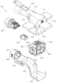
도 1은 본 발명의 일 실시예에 따른 전기차량용 멀티소켓 타입의 충방전커넥터가 인렛커넥터에 접속되는 상태를 보인 사시도이다.
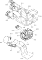
도 2는 본 발명의 일 실시예에 따른 전기차량용 멀티소켓 타입의 충방전커넥터의 분해 사시도이다.
도 3은 본 발명의 일 실시예에 따른 전기차량용 멀티소켓 타입의 충방전커넥터의 배면 분해 사시도이다.
도 4는 본 발명의 일 실시예에 따른 전기차량용 멀티소켓 타입의 충방전커넥터의 저면 분해 사시도이다.
도 5는 본 발명의 일 실시예에 따른 전기차량용 멀티소켓 타입의 충방전커넥터의 배면도이다.
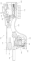
도 6은 본 발명의 일 실시예에 따른 전기차량용 멀티소켓 타입의 충방전커넥터의 단면도이다.
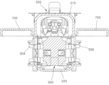
도 7은 도 1의 A-A선 단면도이다.FIG. 1 is a perspective view showing a state in which a multi-socket type charging/discharging connector for an electric vehicle according to one embodiment of the present invention is connected to an inlet connector.
FIG. 2 is an exploded perspective view of a multi-socket type charging/discharging connector for an electric vehicle according to one embodiment of the present invention.
FIG. 3 is an exploded perspective view of the back of a multi-socket type charging/discharging connector for an electric vehicle according to one embodiment of the present invention.
FIG. 4 is a bottom exploded perspective view of a multi-socket type charging/discharging connector for an electric vehicle according to one embodiment of the present invention.
FIG. 5 is a rear view of a multi-socket type charging/discharging connector for an electric vehicle according to one embodiment of the present invention.
FIG. 6 is a cross-sectional view of a multi-socket type charging/discharging connector for an electric vehicle according to one embodiment of the present invention.
Figure 7 is a cross-sectional view taken along line AA of Figure 1.
이하, 첨부된 도면들을 참조하여 본 발명에 따른 전기차량용 멀티소켓 타입의 충방전커넥터의 실시예를 설명한다. 이 과정에서 도면에 도시된 선들의 두께나 구성요소의 크기 등은 설명의 명료성과 편의상 과장되게 도시되어 있을 수 있다. 또한, 후술되는 용어들은 본 발명에서의 기능을 고려하여 정의된 용어들로서 이는 사용자, 운용자의 의도 또는 관례에 따라 달라질 수 있다. 그러므로 이러한 용어들에 대한 정의는 본 명세서 전반에 걸친 내용을 토대로 내려져야 할 것이다.Hereinafter, with reference to the attached drawings, an embodiment of a multi-socket type charging/discharging connector for electric vehicles according to the present invention will be described. In this process, the thickness of lines and the size of components illustrated in the drawings may be exaggerated for clarity and convenience of explanation. In addition, the terms described below are terms defined in consideration of functions in the present invention, and may vary depending on the intention or custom of the user or operator. Therefore, the definitions of these terms should be made based on the contents throughout this specification.
도 1은 본 발명의 일 실시예에 따른 전기차량용 멀티소켓 타입의 충방전커넥터가 인렛커넥터에 접속되는 상태를 보인 사시도이다.FIG. 1 is a perspective view showing a state in which a multi-socket type charging/discharging connector for an electric vehicle according to one embodiment of the present invention is connected to an inlet connector.
도 2는 본 발명의 일 실시예에 따른 전기차량용 멀티소켓 타입의 충방전커넥터의 분해 사시도이고, 도 3은 본 발명의 일 실시예에 따른 전기차량용 멀티소켓 타입의 충방전커넥터의 배면 분해 사시도이며, 도 4는 본 발명의 일 실시예에 따른 전기차량용 멀티소켓 타입의 충방전커넥터의 저면 분해 사시도이다.FIG. 2 is an exploded perspective view of a multi-socket type charging/discharging connector for an electric vehicle according to one embodiment of the present invention, FIG. 3 is an exploded perspective view of the back of a multi-socket type charging/discharging connector for an electric vehicle according to one embodiment of the present invention, and FIG. 4 is an exploded perspective view of the bottom of a multi-socket type charging/discharging connector for an electric vehicle according to one embodiment of the present invention.
도 5는 본 발명의 일 실시예에 따른 전기차량용 멀티소켓 타입의 충방전커넥터의 배면도이고, 도 6은 본 발명의 일 실시예에 따른 전기차량용 멀티소켓 타입의 충방전커넥터의 단면도이며, 도 7은 도 1의 A-A선 단면도이다.FIG. 5 is a rear view of a multi-socket type charging/discharging connector for an electric vehicle according to one embodiment of the present invention, FIG. 6 is a cross-sectional view of a multi-socket type charging/discharging connector for an electric vehicle according to one embodiment of the present invention, and FIG. 7 is a cross-sectional view taken along line A-A of FIG. 1.
도 1 내지 도 7을 참조하면, 본 발명의 일 실시예에 따른 전기차량용 멀티소켓 타입의 충방전커넥터(100)는 케이싱(200), 외부전원소켓부(300), 충전전원소켓부(400), 커버(700) 및 캡(900)을 포함한다.Referring to FIGS. 1 to 7, a multi-socket type charging/discharging connector (100) for an electric vehicle according to one embodiment of the present invention includes a casing (200), an external power socket portion (300), a charging power socket portion (400), a cover (700), and a cap (900).
특히, 본 발명에 따른 전기차량용 멀티소켓 타입의 충방전커넥터(100)는 외부 전원을 접속하여 차량에 충전 안내하거나, 또는 차량의 전원을 이용하여 외부의 전자제품을 작동 안내하는 역할을 한다.In particular, the multi-socket type charging/discharging connector (100) for electric vehicles according to the present invention serves to guide charging of a vehicle by connecting an external power source, or to guide operation of an external electronic device using the vehicle's power source.
아울러, 본 발명에 따른 전기차량용 멀티소켓 타입의 충방전커넥터(100)는 외부 전원을 동시에 복수 개 접속 허용한다.In addition, the multi-socket type charging/discharging connector (100) for electric vehicles according to the present invention allows multiple external power sources to be connected simultaneously.
상세히, 케이싱(200)은 아웃렛 충전커넥터(100)의 외형을 형성한다. 이때, 케이싱(200)은 사용자가 손으로 잡고 충전을 위해 사용할 수 있도록 절연 재질로 이루어진다.In detail, the casing (200) forms the outer shape of the outlet charging connector (100). At this time, the casing (200) is made of an insulating material so that the user can hold it by hand and use it for charging.
특히, 케이싱(200)은 외부전원소켓부(300)와 충전전원소켓부(400) 등의 조립을 용이하게 하기 위해 어퍼케이스(210)와 로어케이스(220)로 나뉘어지는 것으로 한다.In particular, the casing (200) is divided into an upper case (210) and a lower case (220) to facilitate assembly of the external power socket section (300) and the charging power socket section (400).
어퍼케이스(210)는 둘레면 중 타측이 개방되게 형성된다. 편의상, 어퍼케이스(210)는 하부 방향으로 개방되게 형성되는 것으로 한다.The upper case (210) is formed so that one side of the circumference is open. For convenience, the upper case (210) is formed so that it is open in the downward direction.
그리고, 로어케이스(220)는 어퍼케이스(210)에 분리 가능하게 결합되고, 어퍼케이스(210)의 개방된 타측에 대응되도록 둘레면 중 일측이 개방되게 형성된다. 즉, 로어케이스(220)는 어퍼케이스(210)의 하부 개방에 대응하여 상부 방향으로 개방되게 형성되는 것으로 한다.And, the lower case (220) is detachably connected to the upper case (210), and one side of the circumferential surface is formed to be open to correspond to the open other side of the upper case (210). That is, the lower case (220) is formed to be open upward to correspond to the lower opening of the upper case (210).
물론, 어퍼케이스(210)와 로어케이스(220)는 다양한 방식으로 분리 가능하게 조립될 수 있다.Of course, the upper case (210) and the lower case (220) can be assembled separately in various ways.
그리고, 외부전원소켓부(300)는 축 방향을 따라 케이싱(200)의 일측에 구비되고, 외부의 전원플러그(10)와 접속 허용한다. 이때, 외부전원소켓부(300)는 복수 개의 전원플러그(10)를 동시에 접속 허용한다.And, the external power socket part (300) is provided on one side of the casing (200) along the axial direction and allows connection with an external power plug (10). At this time, the external power socket part (300) allows connection of multiple power plugs (10) at the same time.
즉, 외부전원소켓부(300)는 축 방향을 따라 케이싱(200)의 일측 둘레면을 통해 복수 개의 전원접속부(302,304,306)를 노출되게 구비하여 전원플러그(10)를 일대일 접속 허용한다.That is, the external power socket part (300) is provided with a plurality of power connection parts (302, 304, 306) exposed through one side of the casing (200) along the axial direction to allow one-to-one connection of the power plug (10).
예로서, 어퍼케이스(210) 또는 로어케이스(220)는 전원접속부(302~306)의 제 1전원접속부(302)가 노출되도록 축 방향을 따라 일측 단면에 제 1개방홀(202)을 통공하고, 전원접속부(302~306)의 제 2전원접속부(304)가 노출되도록 축 방향에 대해 일측면에 제 2개방홀(204)을 통공하며, 전원접속부(302~306)의 제 3전원접속부(306)가 노출되도록 축 방향에 대해 타측면에 제 3개방홀(206)을 통공한다.For example, the upper case (210) or the lower case (220) has a first open hole (202) formed on one side of the cross section along the axial direction so that the first power connection portion (302) of the power connection portions (302 to 306) is exposed, a second open hole (204) formed on one side of the cross section so that the second power connection portion (304) of the power connection portions (302 to 306) is exposed, and a third open hole (206) formed on the other side of the cross section so that the third power connection portion (306) of the power connection portions (302 to 306) is exposed.
특히, 제 1개방홀(202), 제 2개방홀(204) 및 제 3개방홀(206)은 어퍼케이스(210)의 해당되는 일측 단면과 양측면에 각각 형성되는 것으로 한다.In particular, the first open hole (202), the second open hole (204), and the third open hole (206) are formed on the corresponding one-sided cross-section and both sides of the upper case (210), respectively.
아울러, 제 1개방홀(202)을 통해 노출되는 제 1전원접속부(302), 제 2개방홀(204)을 통해 노출되는 제 2전원접속부(304), 제 3개방홀(206)을 통해 노출되는 제 3전원접속부(306)은 각각 전원플러그(10)를 접속 허용하기 위해 적어도 한 쌍의 접속홀을 형성한다.In addition, the first power connection part (302) exposed through the first open hole (202), the second power connection part (304) exposed through the second open hole (204), and the third power connection part (306) exposed through the third open hole (206) each form at least one pair of connection holes to allow connection of a power plug (10).
이때, 외부전원소켓부(300)는 어퍼케이스(210) 또는 로어케이스(220)의 내측에 분리 가능하게 결합될 수 있고, 다양한 형상으로 변형 가능하다.At this time, the external power socket part (300) can be detachably connected to the inside of the upper case (210) or the lower case (220) and can be transformed into various shapes.
제 1전원접속부(302)는 제 1개방홀(202)의 내측면에 접하여 위치 고정될 수 있고, 제 2전원접속부(304)는 제 2개방홀(204)의 내측면에 접하여 위치 고정될 수 있으며, 제 3전원접속부(306)는 제 3개방홀(206)의 내측면에 접하여 위치 고정될 수 있다.The first power connection part (302) can be fixed in position by contacting the inner surface of the first open hole (202), the second power connection part (304) can be fixed in position by contacting the inner surface of the second open hole (204), and the third power connection part (306) can be fixed in position by contacting the inner surface of the third open hole (206).
또한, 충전전원소켓부(400)는 축 방향을 따라 케이싱(200)의 타측에 구비되고, 외부전원소켓부(300)와 전기적으로 연결되며, 인렛커넥터(20)와 접속된다. 이때, 충전전원소켓부(400)는 차체에 고정되는 인렛커넥터(20)에 접속될 수 있도록 케이싱(200)의 타측으로 일부 돌출되게 구비된다. 물론, 충전전원소켓부(400)는 케이싱(200)에 다양한 방식으로 고정될 수 있다.In addition, the charging power socket part (400) is provided on the other side of the casing (200) along the axial direction, is electrically connected to the external power socket part (300), and is connected to the inlet connector (20). At this time, the charging power socket part (400) is provided to protrude partially from the other side of the casing (200) so that it can be connected to the inlet connector (20) fixed to the vehicle body. Of course, the charging power socket part (400) can be fixed to the casing (200) in various ways.
다시 말해서, 축 방향을 따라 어퍼케이스(210)의 타측과, 이에 대응되는 로어케이스(220)의 타측은 충전전원소켓부(400)를 감싸서 고정한다. 이에 따라, 어퍼케이스(210)의 타측 단부와, 이에 대응되는 로어케이스(220)의 타측 단부는 대략 일직선상에 배치될 수 있다.In other words, the other side of the upper case (210) along the axial direction and the other side of the corresponding lower case (220) wrap around and secure the charging power socket part (400). Accordingly, the other end of the upper case (210) and the other end of the corresponding lower case (220) can be arranged in approximately a straight line.
이때, 충전전원소켓부(400)가 인렛커넥터(20)에 접속된 상태를 유지할 수 있도록, 케이싱(200)은 래치핀(600)을 구비한다. 래치핀(600)은 케이싱(200)에 회동 가능하게 구비되어, 충전전원소켓부(400)와 인렛커넥터(20)가 접속시 인렛커넥터(20)를 구속하는 역할을 한다. At this time, in order to maintain the charging power socket part (400) connected to the inlet connector (20), the casing (200) is provided with a latch pin (600). The latch pin (600) is rotatably provided on the casing (200) and serves to restrain the inlet connector (20) when the charging power socket part (400) and the inlet connector (20) are connected.
이때, 래치핀(600)은 피벗핀(610)에 의해 케이싱(200) 특히 어퍼케이스(210)에 대해 시소 운동 가능하게 구비된다. 아울러, 래치핀(600)은 축 방향을 따라 피벗핀(610)을 기준으로 일측 또는 양측이 탄성부재(620)에 의해 탄성적으로 회동 안내된다. 이로써, 충전전원소켓부(400)가 인렛커넥터(20)에 접속 후, 래치핀(600)은 일측이 인렛커넥터(20)를 결속한다. 사용자가 래치핀(600)의 타측을 누를 경우, 래치핀(600)의 일측은 인렛커넥터(20)와의 결속을 해제하게 된다.At this time, the latch pin (600) is provided to be able to seesaw with respect to the casing (200), especially the upper case (210), by the pivot pin (610). In addition, the latch pin (600) is elastically guided to rotate on one or both sides of the pivot pin (610) along the axial direction by the elastic member (620). Accordingly, after the charging power socket part (400) is connected to the inlet connector (20), one side of the latch pin (600) engages the inlet connector (20). When the user presses the other side of the latch pin (600), one side of the latch pin (600) is released from engagement with the inlet connector (20).
물론, 래치핀(600)은 다양한 형상으로 변형 가능하다.Of course, the latch pin (600) can be transformed into various shapes.
그리고, 로어케이스(220)는 손잡이 역할을 위해 외측 둘레면에 오목부(222)를 형성할 수 있다. 특히, 로어케이스(220)는 둘레면 중 개방된 타측에 대응되는 일측 둘레면에 오목부(222)를 형성할 수 있다. 오목부(222)는 손잡이 역할을 하는 것으로 한다.In addition, the lower case (220) may form a concave portion (222) on the outer circumferential surface to function as a handle. In particular, the lower case (220) may form a concave portion (222) on one circumferential surface corresponding to the open side of the circumferential surface. The concave portion (222) is intended to function as a handle.
특히, 외부전원소켓부(300)는 전원플러그(10)와 접속될 수 있도록 케이싱(200)의 일측으로 일부가 직접적으로 노출되게 구비된다. 이 경우, 외부전원소켓부(300)는 빗물 등 외부 환경에 노출됨에 따라 전원플러그(10)와 접속시 감전, 내구성 저하 등의 우려가 있다.In particular, the external power socket part (300) is provided so that a part thereof is directly exposed to one side of the casing (200) so that it can be connected to the power plug (10). In this case, there is a risk of electric shock or reduced durability when the external power socket part (300) is connected to the power plug (10) as it is exposed to the external environment such as rainwater.
이를 방지하기 위해, 어퍼케이스(210) 또는 로어케이스(220)는 제 1개방홀(202), 제 2개방홀(204) 및 제 3개방홀(206) 각각을 개폐하는 커버(700)를 구비할 수 있다. To prevent this, the upper case (210) or the lower case (220) may be provided with a cover (700) that opens and closes each of the first opening hole (202), the second opening hole (204), and the third opening hole (206).
이때, 커버(700)는 제 1개방홀(202), 제 2개방홀(204) 및 제 3개방홀(206) 각각을 개별적으로 개폐할 수 있도록 어퍼케이스(210)에 힌지 연결되는 것을 한다. 물론, 커버(700)는 다양한 형상으로 적용 가능하고, 다양한 방식으로 어퍼케이스(210)에 연결되거나 개별적으로 구비될 수 있다. 다시 말해서, 커버(700)는 어퍼케이스(210)에서 서로 다른 방향으로 개방되는 제 1개방홀(202), 제 2개방홀(204) 및 제 3개방홀(206) 각각에 대응되는 외부전원소켓부(300)의 제 1전원접속부(302)와 제 2전원접속부(304) 및 제 3전원접속부(306) 각각을 개폐한다. At this time, the cover (700) is hinge-connected to the upper case (210) so that the first opening hole (202), the second opening hole (204), and the third opening hole (206) can be individually opened and closed. Of course, the cover (700) can be applied in various shapes, and can be connected to the upper case (210) or individually provided in various ways. In other words, the cover (700) opens and closes the first power connection part (302), the second power connection part (304), and the third power connection part (306) of the external power socket part (300) corresponding to the first opening hole (202), the second opening hole (204), and the third opening hole (206) which open in different directions in the upper case (210), respectively.
아울러, 외부전원소켓부(300)는 전원플러그(10)와 접속되어 충전과정 등에 의해 과온 발생시 화재를 방지하도록 전력을 차단하는 바이메탈스위치(310)를 연결한다.In addition, the external power socket (300) is connected to a power plug (10) and a bimetal switch (310) that cuts off power to prevent fire when overheating occurs during the charging process, etc.
그리고, 외부전원소켓부(300)는 충전전원소켓부(400)와 전기적 접속을 안내하기 위해 접속커넥터(320)를 접속할 수 있다.In addition, the external power socket part (300) can connect a connection connector (320) to guide electrical connection with the charging power socket part (400).
이때, 외부전원소켓부(300)는 접속커넥터(320)를 견고하게 고정하기 위해 홀더(330)를 구비할 수 있다.At this time, the external power socket part (300) may be equipped with a holder (330) to firmly fix the connection connector (320).
홀더(330)는 다양하게 형성될 수 있으나, 편의상 접속커넥터(320)를 수용하여 고정하도록 형성되는 것으로 한다.The holder (330) can be formed in various ways, but for convenience, it is formed to accommodate and secure the connection connector (320).
아울러, 외부전원소켓부(300)는 삽입되며 접속되는 전원플러그(10)의 정위치 접속 및 흔들림 방지를 위해 전원접속부(302,304,306) 각각의 전측면으로 돌출되는 접속가이드편(340)을 구비할 수 있다.In addition, the external power socket part (300) may be provided with a connection guide piece (340) protruding from the front side of each of the power connection parts (302, 304, 306) to ensure correct positioning and prevent shaking of the power plug (10) that is inserted and connected.
접속가이드편(340)은 외부전원소켓부(300)의 전원접속부(302,304,306) 각각에 접속되는 전원플러그(10)의 외형을 따라 연속 또는 비연속되는 궤적을 따라 전원접속부(302,304,306)의 표면에서 돌출되는 것으로 한다.The connection guide piece (340) is configured to protrude from the surface of the power connection portion (302, 304, 306) along a continuous or discontinuous trajectory along the outer shape of the power plug (10) connected to each of the power connection portions (302, 304, 306) of the external power socket portion (300).
또한, 개방된 타측(하측)에 반대되는 어퍼케이스(210)의 일측(상측) 둘레면은 접선 방향이 외부전원소켓부(300)의 제 1전원접속부(302), 제 2전원접속부(304) 및 제 3전원접속부(306)의 표면의 접선 방향과 수직하게 형성된다.In addition, the periphery of one side (upper side) of the upper case (210) opposite to the open side (lower side) is formed so that the tangent direction is perpendicular to the tangential direction of the surfaces of the first power connection part (302), the second power connection part (304), and the third power connection part (306) of the external power socket part (300).
이로써, 외부전원소켓부(300)의 제 1전원접속부(302), 제 2전원접속부(304) 및 제 3전원접속부(306)에 각각 접속되는 전원플러그(10)의 케이블(12)은 꺾임 현상이 발생되지 않게 된다.Accordingly, the cable (12) of the power plug (10) connected to the first power connection part (302), the second power connection part (304), and the third power connection part (306) of the external power socket part (300) is prevented from being bent.
그리고, 케이싱(200)의 외부로 노출되는 충전전원소켓부(400)는 미사용시 캡(900)에 의해 보호된다. 캡(900)은 충전전원소켓부(400)의 일부를 덮어 보호하는 것으로서, 다양한 형상으로 변형 가능하다. 물론, 캡(900)은 다양한 재질로 적용 가능하다.And, the charging power socket part (400) exposed to the outside of the casing (200) is protected by a cap (900) when not in use. The cap (900) covers and protects a part of the charging power socket part (400) and can be transformed into various shapes. Of course, the cap (900) can be applied with various materials.
아울러, 케이싱(200)은 충전전원소켓부(400)로부터 분리된 캡(900)의 분실을 방지하기 위해 캡(900)과 커넥팅부재(910)로써 연결한다. 즉, 커넥팅부재(910)는 어퍼케이스(210) 또는 로어케이스(220)와 캡(900)을 연결한다. 이때, 커넥팅부재(910)는 어퍼케이스(210) 또는 로어케이스(220)에 분리 가능하게 연결될 수 있다. 물론, 커넥팅부재(910)는 다양한 형상으로 적용 가능하다.In addition, the casing (200) is connected to the cap (900) by a connecting member (910) to prevent the loss of the cap (900) separated from the charging power socket (400). That is, the connecting member (910) connects the cap (900) to the upper case (210) or the lower case (220). At this time, the connecting member (910) can be detachably connected to the upper case (210) or the lower case (220). Of course, the connecting member (910) can be applied in various shapes.
그리고, 케이싱(200) 특히 어퍼케이스(210) 또는 로어케이스(220)는 전류의 흐름을 단속하는 단속스위치(110)를 구비할 수 있다. 단속스위치(110)는 외부전원소켓부(300)와 충전전원소켓부(400)의 전기적 연결을 단속하는 역할을 한다.And, the casing (200), especially the upper case (210) or lower case (220), may be equipped with a cut-off switch (110) that cuts off the flow of current. The cut-off switch (110) serves to cut off the electrical connection between the external power socket section (300) and the charging power socket section (400).
또한, 캡(900)는 충전전원소켓부(400)를 씌워 보호하거나 충전전원소켓부(400)로부터 분리시 손으로 잡을 수 있도록 그립돌기(912)를 돌출 형성할 수 있다.In addition, the cap (900) can be formed with a grip projection (912) that protrudes to protect the charging power socket part (400) or to allow it to be held by hand when separated from the charging power socket part (400).
사용자가 그립돌기(912)를 잡고 캡(900)을 이동시킴에 따라, 사용자는 충전전원소켓부(400)로부터 캡(900)을 분리하기 위해 가하는 외력을 줄일 수 있다. 물론, 그립돌기(912)는 다양한 형상으로 변형 가능하다.As the user holds the grip protrusion (912) and moves the cap (900), the user can reduce the external force applied to separate the cap (900) from the charging power socket part (400). Of course, the grip protrusion (912) can be transformed into various shapes.
결과적으로, 본 발명에 따른 아웃렛 충전커넥터(100)는 규격화된 전기차량의 인렛커넥터(20)를 그대로 활용하여 충전시 뿐만 아니라 외부에서 전기차량의 배터리를 활용한 전력을 사용하고자 할 때, 인렛커넥터(20)에 접속하여 전력을 외부의 전자제품에 전송할 수 있다. 그리고, 외부전원소켓부(300)는 제 1전원접속부(302), 제 2전원접속부(304) 및 제 3전원접속부(306)를 케이싱(200)의 외부로 노출되게 구비하여 전원플러그(10)를 일대일 접속 허용함으로써 사용상 편의성을 제공한다.As a result, the outlet charging connector (100) according to the present invention can transmit power to an external electronic product by connecting to the inlet connector (20) not only when charging but also when using power from the battery of the electric vehicle externally by using the inlet connector (20) as it is of a standardized electric vehicle. In addition, the external power socket part (300) provides convenience in use by exposing the first power connection part (302), the second power connection part (304), and the third power connection part (306) to the outside of the casing (200) to allow one-to-one connection of the power plug (10).
본 발명은 도면에 도시된 실시예를 참고로 하여 설명되었으나, 이는 예시적인 것에 불과하며, 당해 기술이 속하는 분야에서 통상의 지식을 가진 자라면 이로부터 다양한 변형 및 균등한 타 실시예가 가능하다는 점을 이해할 것이다. Although the present invention has been described with reference to the embodiments shown in the drawings, these are merely exemplary, and those skilled in the art will understand that various modifications and equivalent other embodiments are possible therefrom.
따라서 본 발명의 진정한 기술적 보호범위는 아래의 청구범위에 의해서 정하여져야 할 것이다.Therefore, the true technical protection scope of the present invention should be defined by the claims below.
10: 전원플러그 20: 인렛커넥터
100: 충방전커넥터 200: 케이싱
202: 제 1개방홀 204: 제 2개방홀
206: 제 3개방홀 210: 어퍼케이스
220: 로어케이스 222: 오목부
300: 외부전원소켓부 302: 제 1전원접속부
304: 제 2전원접속부 306: 제 3전원접속부
310: 바이메탈스위치 320: 접속커넥터
330: 홀더 340: 접속가이드편
400: 충전전원소켓부 600: 래치핀
610: 피벗핀 620: 탄성부재
700: 커버 900: 캡
910: 커넥팅부재 912: 그립돌기10: Power plug 20: Inlet connector
100: Charge/discharge connector 200: Casing
202: 1st open room 204: 2nd open room
206: 3rd open room 210: Upper case
220: Lower case 222: Concave
300: External power socket section 302: First power connection section
304: Second power connection 306: Third power connection
310: Bimetal switch 320: Connection connector
330: Holder 340: Connection Guide
400: Charging power socket 600: Latch pin
610: Pivot pin 620: Elastic member
700: Cover 900: Cap
910: Connecting member 912: Grip protrusion
Claims (5)
축 방향을 따라 상기 케이싱의 일측에 구비되고, 외부의 전원플러그와 접속 허용하는 복수 개의 외부전원소켓부;
축 방향을 따라 상기 케이싱의 타측에 구비되고, 복수 개인 상기 외부전원소켓부와 일대일 전기적으로 연결되며, 인렛커넥터와 접속 안내되는 충전전원소켓부; 및
상기 외부전원소켓부의 노출을 막거나 외부 노출을 허용하기 위해, 상기 케이싱에 구비되는 커버를 포함하는 것을 특징으로 하는 전기차량용 멀티소켓 타입의 충방전커넥터.
casing;
A plurality of external power sockets provided on one side of the casing along the axial direction and allowing connection with an external power plug;
A charging power socket section provided on the other side of the casing along the axial direction, electrically connected one-to-one with a plurality of individual external power socket sections, and guided to be connected with an inlet connector; and
A multi-socket type charging/discharging connector for an electric vehicle, characterized in that it includes a cover provided on the casing to prevent exposure of the external power socket part or allow external exposure.
상기 외부전원소켓부와 상기 충전전원소켓부의 일부를 내부에 수용하기 위해, 둘레면 중 하측으로 개방되는 내부공간을 형성하는 어퍼케이스; 및
상기 외부전원소켓부와 상기 충전전원소켓부의 나머지를 내부에 안착하기 위해 둘레면 중 상측으로 개방되는 내부공간을 형성하고, 상기 어퍼케이스에 분리 가능하게 결합되는 로어케이스를 포함하는 것을 특징으로 하는 전기차량용 멀티소켓 타입의 충방전커넥터.
In the first paragraph, the casing,
An upper case forming an internal space that is open toward the lower side of the circumference to accommodate the external power socket part and a part of the charging power socket part inside; and
A multi-socket type charging/discharging connector for an electric vehicle, characterized in that it forms an internal space that is open toward the upper side of the circumference to accommodate the external power socket part and the remainder of the charging power socket part inside, and includes a lower case that is detachably connected to the upper case.
상기 외부전원소켓부는 축 방향을 따라 상기 케이싱의 일측 둘레면을 통해 복수 개의 전원접속부가 노출되게 구비하여 상기 전원플러그를 일대일 접속 허용하며,
상기 어퍼케이스 또는 상기 로어케이스는 상기 전원접속부의 제 1전원접속부가 노출되도록 축 방향을 따라 일측 단면에 제 1개방홀을 통공하고, 상기 전원접속부의 제 2전원접속부가 노출되도록 축 방향에 대해 일측면에 제 2개방홀을 통공하며, 상기 전원접속부의 제 3전원접속부가 노출되도록 축 방향에 대해 타측면에 제 3개방홀을 통공하고,
상기 어퍼케이스 또는 상기 로어케이스는 상기 제 1개방홀, 상기 제 2개방홀 및 상기 제 3개방홀을 개별적으로 개폐하는 복수 개의 커버를 구비하는 것을 특징으로 하는 전기차량용 멀티소켓 타입의 충방전커넥터.
In the second paragraph,
The above external power socket portion is provided with multiple power connection portions exposed through one side of the casing along the axial direction, allowing one-to-one connection of the power plug.
The upper case or the lower case has a first open hole formed on one side of the cross section along the axial direction so that the first power connection part of the power connection part is exposed, a second open hole formed on one side of the cross section along the axial direction so that the second power connection part of the power connection part is exposed, and a third open hole formed on the other side of the cross section along the axial direction so that the third power connection part of the power connection part is exposed.
A multi-socket type charging/discharging connector for an electric vehicle, characterized in that the upper case or the lower case has a plurality of covers that individually open and close the first opening hole, the second opening hole, and the third opening hole.
상기 어퍼케이스는 개방된 하측에 반대되는 상측면 중 축 방향을 따라 일측 표면의 접선 방향이 축 방향을 따라 상기 로어케이스의 일측 단부에서 노출되는 상기 외부전원소켓부의 표면의 접선 방향과 수직하게 형성되는 것을 특징으로 하는 전기차량용 멀티소켓 타입의 충방전커넥터.
In the second or third paragraph,
The upper case is a multi-socket type charging/discharging connector for electric vehicles, characterized in that the tangent direction of one surface along the axial direction of the upper side opposite to the open lower side is formed perpendicular to the tangent direction of the surface of the external power socket portion exposed from one end of the lower case along the axial direction.
상기 외부전원소켓부는 상기 충전전원소켓부와 전기적 접속을 안내하기 위해 접속커넥터를 구비하고, 상기 접속커넥터를 수용하여 고정하기 위해 홀더를 형성하는 것을 특징으로 하는 전기차량용 멀티소켓 타입의 충방전커넥터. In any one of claims 1 to 3,
A multi-socket type charging/discharging connector for an electric vehicle, characterized in that the external power socket section has a connection connector to guide electrical connection with the charging power socket section, and forms a holder to receive and fix the connection connector.
Priority Applications (1)
| Application Number | Priority Date | Filing Date | Title |
|---|---|---|---|
| KR1020240121178A KR20240141663A (en) | 2022-11-01 | 2024-09-05 | Multi-type charging and discharging connector of electric vehicle |
Applications Claiming Priority (2)
| Application Number | Priority Date | Filing Date | Title |
|---|---|---|---|
| KR1020220143576A KR20240061802A (en) | 2022-11-01 | 2022-11-01 | Multi-type charging and discharging connector of electric vehicle |
| KR1020240121178A KR20240141663A (en) | 2022-11-01 | 2024-09-05 | Multi-type charging and discharging connector of electric vehicle |
Related Parent Applications (1)
| Application Number | Title | Priority Date | Filing Date |
|---|---|---|---|
| KR1020220143576A Division KR20240061802A (en) | 2022-11-01 | 2022-11-01 | Multi-type charging and discharging connector of electric vehicle |
Publications (1)
| Publication Number | Publication Date |
|---|---|
| KR20240141663A true KR20240141663A (en) | 2024-09-27 |
Family
ID=91074339
Family Applications (2)
| Application Number | Title | Priority Date | Filing Date |
|---|---|---|---|
| KR1020220143576A Ceased KR20240061802A (en) | 2022-11-01 | 2022-11-01 | Multi-type charging and discharging connector of electric vehicle |
| KR1020240121178A Ceased KR20240141663A (en) | 2022-11-01 | 2024-09-05 | Multi-type charging and discharging connector of electric vehicle |
Family Applications Before (1)
| Application Number | Title | Priority Date | Filing Date |
|---|---|---|---|
| KR1020220143576A Ceased KR20240061802A (en) | 2022-11-01 | 2022-11-01 | Multi-type charging and discharging connector of electric vehicle |
Country Status (1)
| Country | Link |
|---|---|
| KR (2) | KR20240061802A (en) |
-
2022
- 2022-11-01 KR KR1020220143576A patent/KR20240061802A/en not_active Ceased
-
2024
- 2024-09-05 KR KR1020240121178A patent/KR20240141663A/en not_active Ceased
Also Published As
| Publication number | Publication date |
|---|---|
| KR20240061802A (en) | 2024-05-08 |
Similar Documents
| Publication | Publication Date | Title |
|---|---|---|
| JP6797282B2 (en) | Power connector system | |
| CN102774335B (en) | Power feeding control device | |
| US8651875B2 (en) | Electromechanical pawl for controlling vehicle charge inlet access | |
| EP2858848B1 (en) | Manufacturing service disconnect that is part of busbar | |
| US20130095678A1 (en) | Charging connector | |
| CN110775168A (en) | Charging port cover assembly and method | |
| KR101823584B1 (en) | Battery Pack | |
| KR102093597B1 (en) | Outlet charging plug for electric vehicle | |
| EP1826841B1 (en) | Charging apparatus | |
| KR20140067346A (en) | Charging inlet apparatus for electric vehicle with fast and slow charging used | |
| JP5402539B2 (en) | Charger cooling structure and in-vehicle equipment cooling system | |
| WO2017201033A1 (en) | Push fit main battery terminal connectors with geometrical lockout features | |
| KR20240141663A (en) | Multi-type charging and discharging connector of electric vehicle | |
| WO2023205304A1 (en) | Self locking ev charging adapter | |
| KR102728221B1 (en) | Outlet charging plug for electric vehicle | |
| KR102093598B1 (en) | Outlet charging plug for electric vehicle | |
| KR102128324B1 (en) | A cover to prevent foreign substances from entering the charged inlet of an electric vehicle | |
| EP4302381A1 (en) | Power tool battery charger | |
| KR102655226B1 (en) | Outlet charging plug for electric vehicle | |
| KR20240125898A (en) | Charging and discharging connector of electric vehicle | |
| KR20170093269A (en) | Power plug for electric vehicle having a temparature sensor and an european type terminal and menufacturing method therof | |
| KR20250001200A (en) | Assembly and replace facilitate module type charging and discharging connector of electric vehicle | |
| KR102748898B1 (en) | Outlet charging plug for electric vehicle | |
| KR20170087121A (en) | Power plug for electric vehicle having a temparature sensor and an american type terminal and menufacturing method therof | |
| KR102655224B1 (en) | Power-supply-socket of outlet charge connector |
Legal Events
| Date | Code | Title | Description |
|---|---|---|---|
| A107 | Divisional application of patent | ||
| PA0107 | Divisional application |
Comment text: Divisional Application of Patent Patent event date: 20240905 Patent event code: PA01071R01D Filing date: 20221101 Application number text: 1020220143576 |
|
| PA0201 | Request for examination |
Patent event code: PA02011R04I Patent event date: 20240905 Comment text: Divisional Application of Patent |
|
| PG1501 | Laying open of application | ||
| E902 | Notification of reason for refusal | ||
| PE0902 | Notice of grounds for rejection |
Comment text: Notification of reason for refusal Patent event date: 20241028 Patent event code: PE09021S01D |
|
| E90F | Notification of reason for final refusal | ||
| PE0902 | Notice of grounds for rejection |
Comment text: Final Notice of Reason for Refusal Patent event date: 20241231 Patent event code: PE09021S02D |
|
| E601 | Decision to refuse application | ||
| PE0601 | Decision on rejection of patent |
Patent event date: 20250227 Comment text: Decision to Refuse Application Patent event code: PE06012S01D |
|
| PX0601 | Decision of rejection after re-examination |
Comment text: Decision to Refuse Application Patent event code: PX06014S01D Patent event date: 20250430 Comment text: Decision to Refuse Application Patent event code: PX06011S01I Patent event date: 20250430 |
|
| X601 | Decision of rejection after re-examination |