KR20240117841A - Apparatus and Method for Detecting Net Damage in Aqua Farms through Mesh Hole Grouping Algorithm - Google Patents
Apparatus and Method for Detecting Net Damage in Aqua Farms through Mesh Hole Grouping Algorithm Download PDFInfo
- Publication number
- KR20240117841A KR20240117841A KR1020230010166A KR20230010166A KR20240117841A KR 20240117841 A KR20240117841 A KR 20240117841A KR 1020230010166 A KR1020230010166 A KR 1020230010166A KR 20230010166 A KR20230010166 A KR 20230010166A KR 20240117841 A KR20240117841 A KR 20240117841A
- Authority
- KR
- South Korea
- Prior art keywords
- mesh
- net
- damage
- meshes
- algorithm
- Prior art date
- Legal status (The legal status is an assumption and is not a legal conclusion. Google has not performed a legal analysis and makes no representation as to the accuracy of the status listed.)
- Pending
Links
Images
Classifications
-
- G—PHYSICS
- G06—COMPUTING OR CALCULATING; COUNTING
- G06T—IMAGE DATA PROCESSING OR GENERATION, IN GENERAL
- G06T7/00—Image analysis
- G06T7/0002—Inspection of images, e.g. flaw detection
- G06T7/0004—Industrial image inspection
-
- A—HUMAN NECESSITIES
- A01—AGRICULTURE; FORESTRY; ANIMAL HUSBANDRY; HUNTING; TRAPPING; FISHING
- A01K—ANIMAL HUSBANDRY; AVICULTURE; APICULTURE; PISCICULTURE; FISHING; REARING OR BREEDING ANIMALS, NOT OTHERWISE PROVIDED FOR; NEW BREEDS OF ANIMALS
- A01K61/00—Culture of aquatic animals
- A01K61/10—Culture of aquatic animals of fish
-
- A—HUMAN NECESSITIES
- A01—AGRICULTURE; FORESTRY; ANIMAL HUSBANDRY; HUNTING; TRAPPING; FISHING
- A01K—ANIMAL HUSBANDRY; AVICULTURE; APICULTURE; PISCICULTURE; FISHING; REARING OR BREEDING ANIMALS, NOT OTHERWISE PROVIDED FOR; NEW BREEDS OF ANIMALS
- A01K75/00—Accessories for fishing nets; Details of fishing nets, e.g. structure
-
- G—PHYSICS
- G06—COMPUTING OR CALCULATING; COUNTING
- G06T—IMAGE DATA PROCESSING OR GENERATION, IN GENERAL
- G06T3/00—Geometric image transformations in the plane of the image
- G06T3/40—Scaling of whole images or parts thereof, e.g. expanding or contracting
- G06T3/4015—Image demosaicing, e.g. colour filter arrays [CFA] or Bayer patterns
-
- G—PHYSICS
- G06—COMPUTING OR CALCULATING; COUNTING
- G06T—IMAGE DATA PROCESSING OR GENERATION, IN GENERAL
- G06T7/00—Image analysis
- G06T7/10—Segmentation; Edge detection
- G06T7/11—Region-based segmentation
-
- G—PHYSICS
- G06—COMPUTING OR CALCULATING; COUNTING
- G06T—IMAGE DATA PROCESSING OR GENERATION, IN GENERAL
- G06T7/00—Image analysis
- G06T7/10—Segmentation; Edge detection
- G06T7/13—Edge detection
-
- G—PHYSICS
- G06—COMPUTING OR CALCULATING; COUNTING
- G06T—IMAGE DATA PROCESSING OR GENERATION, IN GENERAL
- G06T7/00—Image analysis
- G06T7/10—Segmentation; Edge detection
- G06T7/155—Segmentation; Edge detection involving morphological operators
-
- G—PHYSICS
- G06—COMPUTING OR CALCULATING; COUNTING
- G06T—IMAGE DATA PROCESSING OR GENERATION, IN GENERAL
- G06T7/00—Image analysis
- G06T7/10—Segmentation; Edge detection
- G06T7/194—Segmentation; Edge detection involving foreground-background segmentation
-
- G—PHYSICS
- G06—COMPUTING OR CALCULATING; COUNTING
- G06T—IMAGE DATA PROCESSING OR GENERATION, IN GENERAL
- G06T7/00—Image analysis
- G06T7/60—Analysis of geometric attributes
-
- G—PHYSICS
- G06—COMPUTING OR CALCULATING; COUNTING
- G06T—IMAGE DATA PROCESSING OR GENERATION, IN GENERAL
- G06T7/00—Image analysis
- G06T7/70—Determining position or orientation of objects or cameras
Landscapes
- Engineering & Computer Science (AREA)
- Physics & Mathematics (AREA)
- General Physics & Mathematics (AREA)
- Theoretical Computer Science (AREA)
- Computer Vision & Pattern Recognition (AREA)
- Life Sciences & Earth Sciences (AREA)
- Environmental Sciences (AREA)
- Animal Husbandry (AREA)
- Biodiversity & Conservation Biology (AREA)
- Marine Sciences & Fisheries (AREA)
- Zoology (AREA)
- Geometry (AREA)
- Quality & Reliability (AREA)
- Image Processing (AREA)
Abstract
Description
본 발명은 수중 그물 파손 탐지에 관한 것으로, 구체적으로 메쉬 홀 그룹핑(Mesh-hole Grouping) 알고리즘을 적용하여 인접한 그물코 간의 집합 형성을 통해 촬영된 영역 그대로 그물 파손 검사를 진행할 수 있도록 한 MHG 알고리즘을 이용한 양식장의 그물 파손 탐지를 위한 장치 및 방법에 관한 것이다.The present invention relates to detection of underwater net breakage, and specifically, to a fish farm using the MHG algorithm, which enables inspection of net breakage in the captured area by applying the mesh-hole grouping algorithm to form a set between adjacent meshes. It relates to a device and method for detecting net damage.
가두리 양식장에서는 양식어가 그물을 깨물거나, 그물 밖의 어류가 양식어류를 사냥하기 위한 포식 활동에 의해 그물의 파손이 발생한다.In cage farms, net damage occurs when fish bite the net or when fish outside the net engage in predatory activities to hunt farmed fish.
또한 그물에 패조류가 성장하면서 그물의 무게가 무거워져 해저면과 마찰에 의해 그물에 구멍이 생기기도 하며, 양식어가 패조류를 뜯어먹으면서 그물에 파손이 생긴다.Additionally, as shellfish grow on the net, the weight of the net becomes heavier, causing holes in the net due to friction with the seafloor, and damage to the net occurs as farmed fish eat the shellfish.
이러한 파손은 양식어에 대한 손실을 야기하기 때문에 지속적인 관리와 빠른 대처가 필요하다.Since such damage causes loss of farmed fish, continuous management and quick response are required.
현재 양식장에서는 다이버를 직접 투입하거나 그물 전체를 교체하는 것으로 그물 파손을 관리했다. 하지만, 이는 가두리 양식장의 크기가 클수록 사람이 직접 그물을 관리하는 것은 비효율적이며 그물 교체 또한 어렵다. Currently, fish farms manage net damage by directly deploying divers or replacing the entire net. However, the larger the cage fish farm, the more inefficient it is to manually manage the nets, and the more difficult it is to replace the nets.
이로 인해 최근 무인 잠수정인 ROV(Remotely operated Vehicle) 또는 AUV(Autonomous Underwater Vehicle)를 통해 사람이 직접 수중에 투입되지 않고도 수중 그물 상태를 확인할 수 있고, 이를 통해 획득한 수중 영상으로 그물 파손을 탐지하는 연구가 진행되고 있다.As a result, research has recently been conducted on unmanned underwater vehicles such as ROV (Remotely operated Vehicle) or AUV (Autonomous Underwater Vehicle) to check the condition of underwater nets without having to put people directly in the water, and to detect net damage using underwater images obtained through these. is in progress.
하지만, 실제 가두리 양식장에서는 조류에 의해 그물이 울렁거릴 뿐만 아니라 ROV와 그물 간의 거리가 일정하지 않다. 이로 인해 획득한 영상에서 그물코 간의 넓이가 서로 다르게 보이는 원근감이 발생하게 된다.However, in actual cage fish farms, not only are the nets turbulent due to currents, but the distance between the ROV and the net is not constant. This creates a sense of perspective in which the widths between the meshes appear different in the acquired images.
도 1은 원근감으로 인한 그물코 간의 픽셀값 차이를 나타낸 구성도이다.Figure 1 is a configuration diagram showing the difference in pixel values between meshes due to perspective.
원근감으로 인해 원래는 모두 같은 넓이로 제작된 그물코가 도 1에서와 같이 카메라에 가까울수록 크게 보이고 멀리 있을수록 작게 보이게 된다.Due to perspective, the mesh, which was originally made to have the same area, appears larger the closer it is to the camera, and appears smaller the farther away it is, as shown in Figure 1.
이는 그물코의 넓이를 통해 그물 파손을 찾고자 할 때, 카메라에 가까운 그물코의 경우 파손이 아님에도 넓이가 넓게 측정되어 오탐을 유발하는 원인이 된다.This is the cause of false positives because when trying to find mesh damage through the area of the mesh, the area of the mesh close to the camera is measured widely even though it is not damaged.
이와 같이 실제 양식장에서는 조류로 인해 발생하는 원근감이 발생하며, 이로 인해 그물 파손이 작게 보여 탐지가 어렵거나 정상인 그물이 파손으로 탐지될 수 있으므로 원근감에 대한 해결이 필요하다. In this way, perspective caused by currents occurs in actual fish farms, and as a result, net damage may appear small and difficult to detect, or normal nets may be detected as damaged, so it is necessary to address perspective.
한편, 종래 기술에서는 수중 그물 파손 탐지 연구는 이미지 처리를 이용한 파손 탐지, 딥러닝을 이용한 파손 탐지가 진행되었다. Meanwhile, in the prior art, underwater net damage detection research was conducted on damage detection using image processing and damage detection using deep learning.
Yun-peng Zhao et al.은 이미지 처리 기법을 통해 그물 파손을 탐지하였다. Yun-peng Zhao et al. detected net damage through image processing techniques.
ROI(Region of interest) 내의 이미지를 Ostu Thresholding을 이용해 바이너리 이미지로 만들고 그물 구멍 면적에 따른 기울기 히스토그램을 계산하여 그물 파손을 탐지하였다. 설계한 알고리즘 평가를 위해 비선형 파도 수로에서 손상된 그물을 설치하여 그물 파손 탐지 실험을 진행했다.The image within the ROI (Region of interest) was converted into a binary image using Ostu Thresholding, and the slope histogram according to the net hole area was calculated to detect net breakage. To evaluate the designed algorithm, a net damage detection experiment was conducted by installing a damaged net in a nonlinear wave channel.
Jeong et al.은 Deep CNN(Deep Convolutional Neural Networks)를 이용해 그물의 찢김 여부를 판단하였다. 타원 생성 함수를 이용해 정상적인 그물 이미지에 찢김 현상을 구현하였다. 훈련 데이터 수를 증가시키기 위해 회전, 반전, 평행이동 등의 Affine transformation과 파도, 조류 등의 움직임 변형을 구현하는 warping 기법을 사용했다. 5-Fold 교차 검증을 통해 4가지의 Deep CNN 비교하는 실험을 진행했다.Jeong et al. used Deep Convolutional Neural Networks (Deep CNN) to determine whether the net was torn. The tearing phenomenon was implemented in a normal net image using an ellipse generation function. To increase the number of training data, we used affine transformations such as rotation, reversal, and parallel movement, and warping techniques that implement movement transformations such as waves and currents. We conducted an experiment comparing four deep CNNs through 5-Fold cross-validation.
Liao et al.은 multi-scale fusion과 MobileNet-SSD 모델을 이용하여 수중 이미지를 개선하고 그물 파손을 탐지했다. 이를 위하여 원양 양식장에서는 정상 이미지를 획득하고, 손상된 이미지는 데이터 이미지 처리 소프트웨어와 실내 양식장에 손상된 그물을 설치하여 획득했다. 획득한 이미지를 기반으로 그물 파손 인식에 대해 3개의 CNN 모델을 비교하고 최종적으로 MobilNet-SSD를 사용하여 그물 인식을 진행했다.Liao et al. used multi-scale fusion and MobileNet-SSD models to improve underwater images and detect net breakage. For this purpose, normal images were acquired in an ocean fish farm, and damaged images were acquired by using data image processing software and installing damaged nets in an indoor fish farm. Based on the acquired images, three CNN models were compared for net damage recognition, and finally net recognition was performed using MobilNet-SSD.
그러나 이와 같은 종래 기술의 이미지처리 또는 딥러닝을 통해 그물 파손을 탐지하는 기술들은 원근감을 제거하기 위해 추가적인 이미지 변환 과정을 필요로 하고, 해당 과정 중에서 이미지가 잘리면서 실제 촬영되고 있는 영역에 비해 적은 영역에 대해서만 그물 파손 검사를 진행하게 되는 문제가 있다.However, these conventional technologies for detecting net damage through image processing or deep learning require an additional image conversion process to remove perspective, and the image is cut during the process, resulting in a smaller area compared to the area actually being photographed. There is a problem in that net damage inspection is conducted only for .
따라서, 수중에서 조류로 인해 발생하는 원근감에 관계없이 가두리 양식장의 그물 파손을 효율적으로 탐지할 수 있도록 하는 새로운 기술의 개발이 요구되고 있다.Therefore, there is a need for the development of new technologies that can efficiently detect net damage in cage fish farms regardless of the perspective caused by currents in the water.
본 발명은 종래 기술의 수중 그물 파손 탐지 기술의 문제점을 해결하기 위한 것으로, 수중에서 조류로 인해 발생하는 원근감에 관계없이 가두리 양식장의 그물 파손을 효율적으로 탐지할 수 있도록 하는 MHG 알고리즘을 이용한 양식장의 그물 파손 탐지를 위한 장치 및 방법을 제공하는데 그 목적이 있다.The present invention is intended to solve the problems of the underwater net breakage detection technology of the prior art, using the MHG algorithm to efficiently detect net breakage in cage fish farms regardless of the perspective caused by currents in the water. The purpose is to provide a device and method for damage detection.
본 발명은 메쉬 홀 그룹핑(Mesh-hole Grouping) 알고리즘을 적용하여 인접한 그물코 간의 집합 형성을 통해 촬영된 영역 그대로 그물 파손 검사를 진행할 수 있도록 한 MHG 알고리즘을 이용한 양식장의 그물 파손 탐지를 위한 장치 및 방법을 제공하는데 그 목적이 있다.The present invention provides an apparatus and method for detecting net damage in fish farms using the MHG algorithm, which allows inspection of net damage as is in the captured area by applying the mesh-hole grouping algorithm to form a set between adjacent meshes. The purpose is to provide.
본 발명은 Mesh-hole Grouping 알고리즘을 적용하여 각 그물코의 바운딩 박스가 인접한 그물코 간에는 겹치는 것을 이용하여 기준 그물코에 대해 인접한 그물코를 탐색하고, 탐색된 그물코와 기준 그물코를 하나의 집합으로 묶음으로써 원근감으로 인해 발생하는 각 그물코 간의 넓이 차이를 줄일 수 있도록 한 MHG 알고리즘을 이용한 양식장의 그물 파손 탐지를 위한 장치 및 방법을 제공하는데 그 목적이 있다.The present invention applies the Mesh-hole Grouping algorithm to search for meshes adjacent to a reference mesh by using the bounding box of each mesh overlapping between adjacent meshes, and by grouping the searched meshes and the reference meshes into one set, due to perspective. The purpose is to provide a device and method for detecting net damage in fish farms using the MHG algorithm, which can reduce the difference in area between each mesh that occurs.
본 발명은 Mesh-hole Grouping 알고리즘을 적용하여 바이너리 이미지의 그물코를 구별하기 위해 라벨링하고, 바운딩 박스를 이용해 기준 그물코과 인접한 그물코를 선별하여 집합으로 묶고, 형성된 집합 내에서 넓이 비교를 통해 그물 파손을 탐지하고 전체 집합의 탐지 결과를 비교하여 전제 집합에서 동일하게 탐지된 파손의 위치를 최종적으로 이미지에 표시하여 효율적인 그물 파손 검출이 가능하도록 한 MHG 알고리즘을 이용한 양식장의 그물 파손 탐지를 위한 장치 및 방법을 제공하는데 그 목적이 있다.The present invention applies the Mesh-hole Grouping algorithm to label meshes in the binary image to distinguish them, selects meshes adjacent to the reference mesh using a bounding box and groups them into a set, detects mesh damage through area comparison within the formed set, and We provide a device and method for detecting net damage in fish farms using the MHG algorithm, which compares the detection results of the entire set and finally displays the location of the same detected damage in the image on the image, enabling efficient net damage detection. It has a purpose.
본 발명의 다른 목적들은 이상에서 언급한 목적으로 제한되지 않으며, 언급되지 않은 또 다른 목적들은 아래의 기재로부터 당업자에게 명확하게 이해될 수 있을 것이다.Other objects of the present invention are not limited to the objects mentioned above, and other objects not mentioned will be clearly understood by those skilled in the art from the description below.
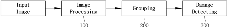
상기와 같은 목적을 달성하기 위한 본 발명에 따른 MHG 알고리즘을 이용한 양식장의 그물 파손 탐지를 위한 장치는 MHG 알고리즘을 이용한 양식장의 그물 파손 탐지를 위하여 적어도 하나의 프로세서를 포함하는 전자 장치가, 입력 이미지에서 그물의 픽셀 값을 0, 그물코의 픽셀 값은 1로 변환한 바이너리 이미지를 출력하는 이미지 프로세싱부;각 그물코의 좌상단 좌표, 너비, 높이, 넓이를 측정하고 라벨링하고, 측정된 좌표와 너비 및 높이를 이용한 바운딩 박스를 통해 기준 그물코와 인접한 그물코를 탐색하여 집합으로 묶는 메쉬 홀 그룹핑부;각 그물코 집합에 대해 넓이 비교를 진행하고 임계값 이상으로 탐지된 그물코를 탐색하여 해당 그물코의 위치를 나타내는 그물 파손 검출부;를 포함하는 것을 특징으로 한다.In order to achieve the above object, the device for detecting net damage in fish farms using the MHG algorithm according to the present invention includes an electronic device including at least one processor to detect net damage in fish farms using the MHG algorithm, An image processing unit that outputs a binary image that converts the pixel value of the mesh to 0 and the pixel value of the mesh to 1; measures and labels the upper left coordinates, width, height, and area of each mesh, and records the measured coordinates, width, and height A mesh hole grouping unit that searches for the reference mesh and adjacent meshes through the bounding box used and groups them into a set; a mesh hole grouping unit that compares the area for each mesh set and searches for meshes detected above the threshold to indicate the location of the corresponding mesh; It is characterized by including ;.
다른 목적을 달성하기 위한 본 발명에 따른 MHG 알고리즘을 이용한 양식장의 그물 파손 탐지를 위한 방법은 적어도 하나의 프로세서를 포함하는 전자 장치에서 MHG 알고리즘을 이용한 양식장의 그물 파손 탐지를 위한 동작이 수행되고,YCbCr 색상 모델의 Cr channel과 CLAHE(Contrast Limited Adaptive Histogram Equalization)을 사용하여 수중 이미지에서 그물 형태를 추출하고 대비를 증가시키는 단계;Ostu Thresholding을 통해 이미지를 바이너리 이미지로 변환하고 Morphology 연산을 통해 이진화 과정에서 끊어진 그물을 보강하는 단계;기준 그물코와 인접한 그물코를 탐색하여 이들을 하나의 집합으로 묶는 Mesh-hole Grouping 기법을 사용하여 Grouping하는 단계;Mesh-hole Grouping을 통해 묶인 각 그물코 집합의 평균 넓이와 1번째와 2번째로 넓은 2개의 그물코 넓이 차를 비교하여 Damage Detecting하는 단계;전체 그물코 집합에 대한 비교 연산 후, 모든 집합에서 동일한 그물코에 대해 임계값 이상으로 파손이라고 탐지했을 경우 해당 그물코의 위치를 바운딩 박스를 통해 표시하는 단계;를 포함하는 것을 특징으로 한다.In a method for detecting net damage in fish farms using the MHG algorithm according to the present invention for achieving another purpose, an operation for detecting net damage in fish farms using the MHG algorithm is performed in an electronic device including at least one processor, YCbCr Extracting the net shape from the underwater image and increasing the contrast using the Cr channel of the color model and CLAHE (Contrast Limited Adaptive Histogram Equalization); Converting the image to a binary image through Ostu Thresholding, and converting the image into a binary image through Morphology operation to remove the broken lines during the binarization process. Step of reinforcing the mesh; Grouping step using the Mesh-hole Grouping technique to search for the reference mesh and adjacent meshes and group them into one set; Average area of each mesh set grouped through Mesh-hole Grouping and the 1st and 2nd Damage detection step by comparing the difference in width of the two widest meshes; After comparing the entire mesh set, if damage is detected beyond the threshold for the same mesh in all sets, the location of the mesh is determined through the bounding box. Characterized in that it includes a display step.
이상에서 설명한 바와 같은 본 발명에 따른 MHG 알고리즘을 이용한 양식장의 그물 파손 탐지를 위한 장치 및 방법은 다음과 같은 효과가 있다.As described above, the device and method for detecting net damage in fish farms using the MHG algorithm according to the present invention has the following effects.
첫째, 수중에서 조류로 인해 발생하는 원근감에 관계없이 가두리 양식장의 그물 파손을 효율적으로 탐지할 수 있도록 한다.First, it allows efficient detection of net damage in cage fish farms regardless of perspective caused by underwater currents.
둘째, 메쉬 홀 그룹핑(Mesh-hole Grouping) 알고리즘을 적용하여 인접한 그물코 간의 집합 형성을 통해 추가적인 이미지 변환 과정 없이 촬영된 영역 그대로 그물 파손 검사를 진행할 수 있도록 한다.Second, the mesh-hole grouping algorithm is applied to form a set between adjacent meshes, allowing mesh damage inspection to be performed on the captured area without additional image conversion process.
셋째, Mesh-hole Grouping 알고리즘을 적용하여 각 그물코의 바운딩 박스가 인접한 그물코 간에는 겹치는 것을 이용하여 기준 그물코에 대해 인접한 그물코를 탐색하고, 탐색된 그물코와 기준 그물코를 하나의 집합으로 묶음으로써 원근감으로 인해 발생하는 각 그물코 간의 넓이 차이를 줄일 수 있도록 한다.Third, by applying the Mesh-hole Grouping algorithm, the bounding box of each mesh overlaps between adjacent meshes to search for meshes adjacent to the reference mesh, and by grouping the searched meshes and the reference meshes into one set, the resulting meshes are detected due to perspective. This helps reduce the difference in area between each mesh.
넷째, Mesh-hole Grouping 알고리즘을 적용하여 바이너리 이미지의 그물코를 구별하기 위해 라벨링하고, 바운딩 박스를 이용해 기준 그물코과 인접한 그물코를 선별하여 집합으로 묶고, 형성된 집합 내에서 넓이 비교를 통해 그물 파손을 탐지하고 전체 집합의 탐지 결과를 비교하여 전제 집합에서 동일하게 탐지된 파손의 위치를 최종적으로 이미지에 표시하여 효율적인 그물 파손 검출이 가능하도록 한다.Fourth, the mesh-hole grouping algorithm is applied to label the meshes in the binary image to distinguish them, the reference meshes and adjacent meshes are selected using a bounding box and grouped into a set, and mesh damage is detected through area comparison within the formed set, and the overall By comparing the detection results of the sets, the location of the same detected breakage in the entire set is finally displayed on the image, enabling efficient net breakage detection.
도 1은 원근감으로 인한 그물코 간의 픽셀값 차이를 나타낸 구성도
도 2는 본 발명에 따른 MHG 알고리즘을 이용한 양식장의 그물 파손 탐지를 위한 장치의 구성도
도 3은 그물코 측정값 설명을 위한 구성도
도 4는 본 발명에 따른 MHG 알고리즘을 이용한 양식장의 그물 파손 탐지를 위한 방법을 나타낸 플로우 차트
도 5는 본 발명에 따른 이미지 프로세싱 과정을 나타낸 흐름도
도 6은 RGB를 이용한 그물 추출의 일 예를 나타낸 구성도
도 7은 다양한 color space에서 그물 추출의 예를 나타낸 구성도
도 8은 Otsu Thresholding 과정을 나타낸 구성도
도 9는 Morphology 연산 결과를 나타낸 구성도
도 10은 그물코 라벨링 결과를 나타낸 구성도
도 11은 각 그물코에 대해 바운딩 박스를 이미지에 나타낸 구성도
도 12는 준 그물코에 대해 바운딩 박스가 겹치는 그물코는 인접한 그물코로 선별한 집합의 일 예를 나타낸 구성도
도 13은 바운딩 박스 크기 증감의 일 예를 나타낸 구성도
도 14는 파손의 위치를 붉은색 바운딩 박스를 사용하여 나타낸 구성도
도 15는 정상 그물 이미지와 파손 생성 결과를 나타낸 구성도
도 16은 붉은색 바운딩 박스를 이용하여 생성된 파손 위치를 모두 나타낸 구성도
도 17은 20도 회전으로 후 일부가 검은색으로 대체된 이미지 구성도
도 18은 sine 변환 적용 결과를 나타낸 구성도
도 19는 임계값 T에 따른 알고리즘의 정확도, 정밀도, 재현도 변화 그래프
도 20은 Image Prcessing 과정에서 그물 형태 손실로 인한 FP 결과를 나타낸 구성도
도 21은 바운딩 박스 증감에 따른 잘못된 집합 형성의 일 예를 나타낸 구성도
도 22는 실제 파손에 대한 그물 파손 탐지 실험을 위한 실헌 기구의 일 예를 나타낸 구성도
도 23은 실제 파손 탐지 결과를 나타낸 구성도Figure 1 is a diagram showing the difference in pixel values between meshes due to perspective.
Figure 2 is a configuration diagram of a device for detecting net damage in fish farms using the MHG algorithm according to the present invention
Figure 3 is a configuration diagram for explaining mesh measurement values
Figure 4 is a flow chart showing a method for detecting net damage in fish farms using the MHG algorithm according to the present invention.
Figure 5 is a flow chart showing the image processing process according to the present invention.
Figure 6 is a configuration diagram showing an example of net extraction using RGB
Figure 7 is a configuration diagram showing examples of net extraction in various color spaces.
Figure 8 is a configuration diagram showing the Otsu Thresholding process
Figure 9 is a configuration diagram showing the results of Morphology calculation
Figure 10 is a configuration diagram showing the mesh labeling results
Figure 11 is a configuration diagram showing the bounding box for each mesh in an image
Figure 12 is a configuration diagram showing an example of a set in which meshes whose bounding boxes overlap with respect to a quasi-mesh are selected as adjacent meshes.
Figure 13 is a configuration diagram showing an example of increasing or decreasing the bounding box size
Figure 14 is a diagram showing the location of damage using a red bounding box.
Figure 15 is a configuration diagram showing a normal net image and damage generation results
Figure 16 is a configuration diagram showing all damage locations created using a red bounding box.
Figure 17 is an image configuration diagram in which part of the image is replaced with black after being rotated 20 degrees.
Figure 18 is a configuration diagram showing the result of applying sine transformation
Figure 19 is a graph of changes in accuracy, precision, and recall of the algorithm according to the threshold T
Figure 20 is a configuration diagram showing the FP results due to net shape loss during the image processing process.
Figure 21 is a configuration diagram showing an example of incorrect set formation according to increase or decrease of the bounding box.
Figure 22 is a configuration diagram showing an example of a real-world mechanism for a net breakage detection experiment for actual breakage.
Figure 23 is a configuration diagram showing the actual damage detection results
이하, 본 발명에 따른 MHG 알고리즘을 이용한 양식장의 그물 파손 탐지를 위한 장치 및 방법의 바람직한 실시 예에 관하여 상세히 설명하면 다음과 같다.Hereinafter, a preferred embodiment of the device and method for detecting net damage in fish farms using the MHG algorithm according to the present invention will be described in detail as follows.
본 발명에 따른 MHG 알고리즘을 이용한 양식장의 그물 파손 탐지를 위한 장치 및 방법의 특징 및 이점들은 이하에서의 각 실시 예에 대한 상세한 설명을 통해 명백해질 것이다.The characteristics and advantages of the device and method for detecting net damage in fish farms using the MHG algorithm according to the present invention will become apparent through the detailed description of each embodiment below.
도 2는 본 발명에 따른 MHG 알고리즘을 이용한 양식장의 그물 파손 탐지를 위한 장치의 구성도이고, 도 3은 그물코 측정값 설명을 위한 구성도이다.Figure 2 is a configuration diagram of a device for detecting net damage in fish farms using the MHG algorithm according to the present invention, and Figure 3 is a configuration diagram for explaining mesh measurement values.
본 개시에서 사용되는 용어는 본 개시에서의 기능을 고려하면서 가능한 현재 널리 사용되는 일반적인 용어들을 선택하였으나, 이는 당 분야에 종사하는 기술자의 의도 또는 판례, 새로운 기술의 출현 등에 따라 달라질 수 있다. 또한, 특정한 경우는 출원인이 임의로 선정한 용어도 있으며, 이 경우 해당되는 발명의 설명 부분에서 상세히 그 의미를 기재할 것이다. 따라서 본 개시에서 사용되는 용어는 단순한 용어의 명칭이 아닌, 그 용어가 가지는 의미와 본 개시의 전반에 걸친 내용을 토대로 정의되어야 한다.The terms used in this disclosure are general terms that are currently widely used as much as possible while considering the functions in this disclosure, but this may vary depending on the intention or precedent of a person working in the art, the emergence of new technology, etc. In addition, in certain cases, there are terms arbitrarily selected by the applicant, and in this case, the meaning will be described in detail in the description of the relevant invention. Therefore, the terms used in this disclosure should be defined based on the meaning of the term and the overall content of this disclosure, rather than simply the name of the term.
명세서 전체에서 어떤 부분이 어떤 구성요소를 "포함"한다고 할 때, 이는 특별히 반대되는 기재가 없는 한 다른 구성요소를 제외하는 것이 아니라 다른 구성요소를 더 포함할 수 있음을 의미한다. 또한, 명세서에 기재된 "...부", "모듈" 등의 용어는 적어도 하나의 기능이나 동작을 처리하는 단위를 의미하며, 이는 하드웨어 또는 소프트웨어로 구현되거나 하드웨어와 소프트웨어의 결합으로 구현될 수 있다.When it is said that a part "includes" a certain element throughout the specification, this means that, unless specifically stated to the contrary, it does not exclude other elements but may further include other elements. In addition, terms such as "... unit" and "module" used in the specification refer to a unit that processes at least one function or operation, which may be implemented as hardware or software, or as a combination of hardware and software. .
특히, 적어도 하나의 기능이나 동작을 처리하는 단위들은 적어도 하나의 프로세서를 포함하는 전자 장치로 구현될 수 있고, 기능이나 동작을 처리하는 방식에 따라 전자 장치에 적어도 하나의 주변 장치가 연결될 수 있다. 주변 장치들은 데이터 입력 장치, 데이터 출력 장치, 데이터 저장 장치를 포함할 수 있다.In particular, units that process at least one function or operation may be implemented as an electronic device including at least one processor, and at least one peripheral device may be connected to the electronic device depending on the method of processing the function or operation. Peripheral devices may include data input devices, data output devices, and data storage devices.
본 발명에 따른 MHG 알고리즘을 이용한 양식장의 그물 파손 탐지를 위한 장치 및 방법은 수중에서 조류로 인해 발생하는 원근감에 관계없이 가두리 양식장의 그물 파손을 효율적으로 탐지할 수 있도록 한 것이다.The device and method for detecting net damage in fish farms using the MHG algorithm according to the present invention enable efficient detection of net damage in cage farms regardless of the perspective caused by currents in the water.
이를 위하여, 본 발명은 메쉬 홀 그룹핑(Mesh-hole Grouping) 알고리즘을 적용하여 인접한 그물코 간의 집합 형성을 통해 촬영된 영역 그대로 그물 파손 검사를 진행할 수 있도록 하는 구성을 포함할 수 있다.To this end, the present invention may include a configuration that allows inspection of mesh damage as is in the imaged area by applying a mesh-hole grouping algorithm to form a set between adjacent meshes.
본 발명은 Mesh-hole Grouping 알고리즘을 적용하여 각 그물코의 바운딩 박스가 인접한 그물코 간에는 겹치는 것을 이용하여 기준 그물코에 대해 인접한 그물코를 탐색하고, 탐색된 그물코와 기준 그물코를 하나의 집합으로 묶음으로써 원근감으로 인해 발생하는 각 그물코 간의 넓이 차이를 줄일 수 있도록 하는 구성을 포함할 수 있다.The present invention applies the Mesh-hole Grouping algorithm to search for meshes adjacent to a reference mesh by using the bounding box of each mesh overlapping between adjacent meshes, and by grouping the searched meshes and the reference meshes into one set, due to perspective. It may include a configuration that reduces the difference in area between each mesh that occurs.
본 발명은 효율적인 그물 파손 검출이 가능하도록 하기 위하여, Mesh-hole Grouping 알고리즘을 적용하여 바이너리 이미지의 그물코를 구별하기 위해 라벨링하고, 바운딩 박스를 이용해 기준 그물코과 인접한 그물코를 선별하여 집합으로 묶고, 형성된 집합 내에서 넓이 비교를 통해 그물 파손을 탐지하고 전체 집합의 탐지 결과를 비교하여 전제 집합에서 동일하게 탐지된 파손의 위치를 최종적으로 이미지에 표시하는 구성을 포함할 수 있다.In order to enable efficient mesh breakage detection, the present invention applies the Mesh-hole Grouping algorithm to label meshes in the binary image to distinguish them, uses a bounding box to select meshes adjacent to the reference mesh and group them into a set, and uses a bounding box to select meshes adjacent to the reference mesh and group them into a set. It may include a configuration that detects net damage through area comparison, compares the detection results of the entire set, and finally displays the location of the same detected damage in the entire set on the image.
본 발명에 따른 MHG 알고리즘을 이용한 양식장의 그물 파손 탐지를 위한 장치는 도 2에서와 같이, 입력 이미지에서 그물의 픽셀 값을 0, 그물코의 픽셀 값은 1로 변환한 바이너리 이미지를 출력하는 이미지 프로세싱부(Image Processing)(100)와, 각 그물코의 좌상단 좌표, 너비, 높이, 넓이를 측정하고 라벨링하고, 측정된 좌표와 너비 및 높이를 이용한 바운딩 박스를 통해 기준 그물코와 인접한 그물코를 탐색하여 집합으로 묶는 메쉬 홀 그룹핑부(Mesh-hole Grouping)(200)와, 각 그물코 집합에 대해 넓이 비교를 진행하고 임계값 이상으로 탐지된 그물코를 탐색하여 해당 그물코의 위치를 나타내는 그물 파손 검출부(Damage Detecting)(300)를 포함한다.As shown in FIG. 2, the device for detecting net damage in fish farms using the MHG algorithm according to the present invention includes an image processing unit that outputs a binary image in which the pixel value of the net is converted to 0 and the pixel value of the mesh is converted to 1 in the input image. (Image Processing) (100), measures and labels the upper left coordinates, width, height, and area of each mesh, searches for meshes adjacent to the reference mesh through a bounding box using the measured coordinates, width, and height, and groups them into a set. A mesh-hole grouping unit (200) and a mesh-hole grouping unit (200), and a mesh damage detection unit (300) that compares the area of each mesh set and searches for meshes detected above a threshold value to indicate the location of the mesh. ) includes.
본 발명에 따른 MHG 알고리즘을 이용한 양식장의 그물 파손 탐지를 위한 방법을 구체적으로 설명하면 다음과 같다.The method for detecting net damage in fish farms using the MHG algorithm according to the present invention will be described in detail as follows.
도 4는 본 발명에 따른 MHG 알고리즘을 이용한 양식장의 그물 파손 탐지를 위한 방법을 나타낸 플로우 차트이다.Figure 4 is a flow chart showing a method for detecting net damage in fish farms using the MHG algorithm according to the present invention.
본 발명에 따른 MHG 알고리즘을 이용한 양식장의 그물 파손 탐지를 위한 방법은 크게 이미지 프로세싱(Image Processing) 단계, 메쉬 홀 그룹핑(Mesh-hole Grouping) 단계, 그물 파손 검출(Damage Detecting) 단계를 포함한다.The method for detecting net damage in fish farms using the MHG algorithm according to the present invention largely includes an image processing step, a mesh-hole grouping step, and a net damage detection step.
Image Processing 단계에서는 수중 이미지에서 그물 형태를 추출하고 대비를 증가시키기 위해 YCbCr 색상 모델의 Cr channel과 CLAHE(Contrast Limited Adaptive Histogram Equalization)을 사용한다.(S401)In the image processing step, the Cr channel of the YCbCr color model and CLAHE (Contrast Limited Adaptive Histogram Equalization) are used to extract the net shape from the underwater image and increase contrast. (S401)
Ostu Thresholding을 통해 이미지를 바이너리 이미지로 변환하고 Morphology 연산을 통해 이진화 과정에서 끊어진 그물을 보강한다.(S402)Convert the image to a binary image through Ostu Thresholding and reinforce the broken net during the binarization process through Morphology calculation (S402).
이어, Grouping 단계에서는 기준 그물코와 인접한 그물코를 탐색하여 이들을 하나의 집합으로 묶는 Mesh-hole Grouping 기법을 사용한다.(S403)Next, in the grouping step, the mesh-hole grouping technique is used to search for meshes adjacent to the reference mesh and group them into one set (S403).
이를 통해 양식장의 수중 환경에서 조류로 인해 이미지에 그물코 간의 원근감이 발생하여도 그물 파손 탐지가 가능하다. 또한, 원근감을 없애기 위해 이미지를 변환[6]하지 않고 그물 파손 탐지가 가능하다. This makes it possible to detect net damage even when the perspective of the mesh occurs in the image due to currents in the aquatic environment of the fish farm. Additionally, mesh breakage detection is possible without transforming the image to eliminate perspective [6].
그리고 Damage Detecting 단계에서는 Mesh-hole Grouping을 통해 묶인 각 그물코 집합의 평균 넓이와 1번째와 2번째로 넓은 2개의 그물코 넓이 차를 비교한다.(S404)And in the Damage Detecting step, the average area of each set of meshes grouped through Mesh-hole Grouping is compared with the difference in the areas of the first and second widest two meshes (S404).
이어, 전체 그물코 집합에 대한 비교 연산 후, 모든 집합에서 동일한 그물코에 대해 임계값 이상으로 파손이라고 탐지했을 경우 해당 그물코의 위치를 바운딩 박스를 통해 나타낸다.(S405)Next, after a comparison operation for the entire mesh set, if damage to the same mesh is detected beyond the threshold in all sets, the location of the mesh is indicated through the bounding box (S405).
이미지 프로세싱(Image Processing) 단계를 구체적으로 설명하면 다음과 같다.The image processing step is described in detail as follows.
도 5는 본 발명에 따른 이미지 프로세싱 과정을 나타낸 흐름도이다.Figure 5 is a flowchart showing the image processing process according to the present invention.
YCbCr 변환과 CLAHE(Contrast Limited Adaptive Histogram Equalization)을 통해 그물 형태를 추출한 후, Otsu Thresholding와 Morpholgy 연산을 통해 바이너리 이미지로 변경 및 그물 형태를 보강을 한다.After extracting the mesh shape through YCbCr conversion and CLAHE (Contrast Limited Adaptive Histogram Equalization), it is converted to a binary image and the mesh shape is reinforced through Otsu Thresholding and Morpholgy operations.
이후, 픽셀 반전을 통해 그물의 픽셀 값은 0, 그물코의 픽셀 값은 1인 바이너리 이미지를 출력한다.Afterwards, through pixel inversion, a binary image is output where the pixel value of the mesh is 0 and the pixel value of the mesh is 1.
YCbCr color space에 관하여 설명하면 다음과 같다.The YCbCr color space is explained as follows.
도 6은 RGB를 이용한 그물 추출의 일 예를 나타낸 구성도이다.Figure 6 is a configuration diagram showing an example of net extraction using RGB.
실제 양식장에 설치된 그물은 패조류의 성장을 막기 위해 붉은색의 방오도료를 그물에 도포한다. 이러한 양식장 그물의 특성에 따라 RGB channel에서 R Channel과 다른 Channel 간의 색차를 이용하여 그물의 형태를 추출한다.Red anti-fouling paint is applied to nets installed in actual fish farms to prevent the growth of shellfish. According to the characteristics of these fish farm nets, the shape of the net is extracted using the color difference between the R Channel and other channels in the RGB channel.
패조류가 없고 방오도료가 잘 부착되어 있는 깨끗한 그물은 RGB 채널 간의 색차를 이용해 도 6의 (a)와 같이 그물 형태를 추출할 수 있다.For a clean net without shellfish and with well-adhered antifouling paint, the net shape can be extracted using the color difference between RGB channels, as shown in (a) of Figure 6.
하지만 방오도료가 점차 벗겨져 패조류가 자라거나, 배경에 다른 물체들이 있는 경우 도 6의 (b),(c)와 같이 RGB color space을 이용했을 때 각 상황마다 적절한 색차 이미지가 달라지며, 그물을 추출하기 어렵다.However, when the antifouling paint gradually peels off and shellfish grows, or when there are other objects in the background, when using the RGB color space as shown in (b) and (c) of Figure 6, the appropriate color difference image varies for each situation, and the net Difficult to extract.
따라서, RGB 외에 HSV, YCbCr, Lab color space을 통해 그물의 색이 붉지 않아도 그물의 형태를 추출하며, 뒷배경의 노이즈를 줄일 수 있는 color space을 탐색한다.Therefore, in addition to RGB, the shape of the net is extracted through HSV, YCbCr, and Lab color space even if the color of the net is not red, and a color space that can reduce background noise is explored.
그 중 RGB를 기반으로 수학식 1에 따라 휘도 성분인 Y와 색차 성분인 Cb, Cr로 변환하는 YCbCr color space을 선택한다.Among them, the YCbCr color space, which converts the luminance component Y and the chrominance components Cb and Cr according to Equation 1 based on RGB, is selected.
각 성분에 대해 수학식 2로 나타낼 수 있으며 Cb는 파란색에서 밝기 성분을 뺀 값, Cr은 붉은색에서 밝기 성분을 뺀 값이다.Each component can be expressed in Equation 2, where Cb is the value obtained by subtracting the brightness component from blue, and Cr is the value obtained by subtracting the brightness component from red.
도 7은 다양한 color space에서 그물 추출의 예를 나타낸 구성도이다.Figure 7 is a configuration diagram showing an example of net extraction in various color spaces.
특히, YCbCr color space에서 Cr channel은 도 7과 같이 다른 color space의 채널에 비해 그물의 형태를 정확히 추출하고 뒷배경에 대한 노이즈가 적은 것을 확인할 수 있다.In particular, it can be seen that the Cr channel in the YCbCr color space accurately extracts the shape of the net and has less noise in the background compared to channels in other color spaces, as shown in Figure 7.
이에 따라 최종적으로 그물 추출을 위해 YCbCr color space의 Cr 채널을 사용한다.Accordingly, the Cr channel of the YCbCr color space is used for final net extraction.
Otsu Thresholding 과정을 설명하면 다음과 같다.The Otsu Thresholding process is explained as follows.
도 8은 Otsu Thresholding 과정을 나타낸 구성도이다.Figure 8 is a configuration diagram showing the Otsu Thresholding process.
이미지를 바이너리 이미지로 변환하기 위해 가장 많이 사용되는 방법은 지정된 임계값을 기준으로 픽셀의 값을 0과 1로 나누는 것으로 이를 Thresholding이라 한다.The most commonly used method to convert an image into a binary image is to divide the pixel value into 0 and 1 based on a specified threshold, which is called thresholding.
임계값에 따라 바이너리 이미지의 출력물이 달라지며 모든 상황에 적절한 바이너리 이미지를 출력하는 임계값을 찾는 것은 어렵다. 이러한 문제를 해결하는 Thresholding 알고리즘이 Otsu Thresholding이다.The output of the binary image varies depending on the threshold, and it is difficult to find a threshold that outputs an appropriate binary image in all situations. The thresholding algorithm that solves this problem is Otsu Thresholding.
Otsu Thresholding은 이미지의 픽셀을 전경과 배경 두 가지 클래스로 분리한다. 그 후 각 클래스 내에 intensity의 분산을 최소화하거나 클래스 간의 분산을 최대화 하는 방식을 통해 이미지에 가장 적절한 임계값을 선택한다.Otsu Thresholding separates pixels in an image into two classes: foreground and background. Then, the most appropriate threshold for the image is selected by minimizing the variance of intensity within each class or maximizing the variance between classes.
이처럼 입력된 이미지에 대해 자동으로 임계값을 계산하는 Otsu Thresholding은 바이너리 이미지를 통한 이미지처리에 유용하다.Otsu Thresholding, which automatically calculates the threshold for the input image, is useful for image processing through binary images.
본 발명에서 사용하는 Cr channel은 대비가 매우 낮은 특성을 가진다.The Cr channel used in the present invention has very low contrast characteristics.
또한, 도 8의 (a)와 같이 수중의 탁한 환경으로 인해 이미지에 haze가 있을 경우, Cr channel에서 haze 영역만 대비가 더욱 낮아져 해당 영역은 배경과 그물 간의 클래스를 분리하기 어려워진다.In addition, when there is haze in the image due to the turbid underwater environment as shown in Figure 8 (a), the contrast of only the haze area in the Cr channel becomes lower, making it difficult to separate the classes between the background and the net in that area.
이로 인해 도 8의 (c)처럼 Thresholding을 거친 후 haze 영역의 그물 형태가 손실되는 문제가 발생한다. 이를 해결하기 위해 영역별로 이미지의 대비를 증가시키는 CLAHE(Contrast Limited Adaptive Histogram Equalization)을 사용하는 것이 바람직하다.As a result, a problem occurs in which the net shape of the haze area is lost after thresholding, as shown in (c) of Figure 8. To solve this, it is desirable to use CLAHE (Contrast Limited Adaptive Histogram Equalization), which increases the contrast of the image for each region.
CLAHE는 하나의 이미지를 n-by-n 그리드로 나누고, 각 그리드에 대해 1개의 histogram을 생성하여 픽셀의 분포를 조정한다. 전체 이미지에 대해 1개의 histogram을 이용하여 픽셀의 분포를 조정하는 Histogram Equalization에 비해 부드러운 대비 증가가 가능하여 Equalization 과정 중 발생하는 노이즈 또한 줄일 수 있다.CLAHE divides one image into n-by-n grids and creates one histogram for each grid to adjust the distribution of pixels. Compared to Histogram Equalization, which adjusts the distribution of pixels using one histogram for the entire image, smooth contrast increase is possible and noise generated during the equalization process can also be reduced.
Morphology 연산에 관하여 설명하면 다음과 같다.Morphology calculation is explained as follows.
도 9는 Morphology 연산 결과를 나타낸 구성도이다.Figure 9 is a configuration diagram showing the results of morphology calculation.
Morphology는 영상 분야에서 노이즈 제거를 위해 사용되는 형태학적 연산이다.Morphology is a morphological operation used to remove noise in the imaging field.
사각형, 타원형 또는 십자형의 구조화 요소 커널을 사용하여 입력된 이미지의 픽셀 형태와 커널 형태를 비교한다. 두 형태가 완전히 겹치지 않을 때 이미지 픽셀 값을 0으로 바꾸는 것이 침식 연산, 픽셀 값을 1로 바꾸는 것을 팽창 연산이라 한다. 침식 연산은 어두운 영역의 노이즈를 제거하고, 팽창 연산은 밝은 영역의 노이즈를 제거한다.Compare the pixel shape of the input image with the kernel shape using square, oval, or cross-shaped structuring element kernels. When the two shapes do not completely overlap, changing the image pixel value to 0 is called an erosion operation, and changing the pixel value to 1 is called a dilation operation. The erosion operation removes noise in dark areas, and the dilation operation removes noise in bright areas.
이러한 침식 연산과 팽창 연산을 복합적으로 사용하여 노이즈 제거와 그림 8과 같이 그물의 형태를 보강할 수 있다.By using these erosion and expansion operations in combination, noise can be removed and the shape of the net can be strengthened as shown in Figure 8.
메쉬 홀 그룹핑(Mesh-hole Grouping) 단계를 구체적으로 설명하면 다음과 같다.The mesh-hole grouping step is described in detail as follows.
도 10은 그물코 라벨링 결과를 나타낸 구성도이다.Figure 10 is a configuration diagram showing the mesh labeling results.
Mesh-hole Grouping은 수중 환경에서 조류로 인한 그물의 울렁거림으로 발생하는 원근감을 해결하기 위한 것이다.Mesh-hole grouping is intended to resolve perspective problems caused by the turbulence of the net due to currents in the underwater environment.
원근감으로 인한 그물코 넓이 차이는 그물코 간의 거리가 멀수록 두드러지게 나타나고, 인접할수록 넓이 차이는 근소하다. 이에 따라 하나의 그물코에 대해 인접한 그물코들을 선별하고 집합으로 형성하는 것이다.The difference in mesh area due to perspective becomes more noticeable the farther the distance between the meshes is, and the closer they are, the smaller the difference in area becomes. Accordingly, adjacent meshes are selected for one mesh and formed into a set.
각 그물코를 구별하고 인접한 그물코를 선별하기 위해 8-way connectivity를 사용하여 도 10에서와 같이 그물코들을 라벨링한다.To distinguish each mesh and select adjacent meshes, 8-way connectivity is used to label the meshes as shown in Figure 10.
8-way connectivity는 상/하/좌/우/대각의 픽셀 간의 연관성을 비교하며 이를 통해 각 그물코 라벨링 뿐만 아니라 그물코의 좌상단 좌표, 너비, 높이, 넓이 또한 측정할 수 있다.8-way connectivity compares the correlation between top/bottom/left/right/diagonal pixels, and through this, not only the labeling of each mesh, but also the upper left coordinates, width, height, and area of the mesh can be measured.
도 11은 각 그물코에 대해 바운딩 박스를 이미지에 나타낸 구성도이고, 도 12는 준 그물코에 대해 바운딩 박스가 겹치는 그물코는 인접한 그물코로 선별한 집합의 일 예를 나타낸 구성도이다.FIG. 11 is a configuration diagram showing the bounding box for each mesh in an image, and FIG. 12 is a configuration diagram showing an example of a set in which meshes whose bounding boxes overlap with respect to a quasi-mesh are selected as adjacent meshes.
본 발명은 그리드를 나누지 않고도 인접한 그물코를 선별할 수 있도록 한 것으로, 이를 위해 각 그물코의 좌상단 좌표와 너비, 높이를 통해 출력할 수 있는 바운딩 박스를 이용한다.The present invention makes it possible to select adjacent meshes without dividing the grid. To this end, a bounding box that can be output through the upper left coordinates, width, and height of each mesh is used.
각 그물코에 대해 바운딩 박스를 이미지에 나타낼 경우, 도 11에서와 같이 인접한 그물코 간에는 바운딩 박스가 겹치는 것을 확인할 수 있다.When the bounding box for each mesh is shown in the image, it can be seen that the bounding boxes overlap between adjacent meshes, as shown in FIG. 11.
따라서 하나의 기준 그물코에 대해 바운딩 박스가 겹치는 그물코는 인접한 그물코로 선별할 수 있으며, 인접한 그물코의 개수는 도 12에서와 같이 최소 2개부터 최대 8개까지 선별되어 집합을 형성할 수 있다.Therefore, meshes whose bounding boxes overlap with one reference mesh can be selected as adjacent meshes, and the number of adjacent meshes can be selected from a minimum of 2 to a maximum of 8 to form a set, as shown in FIG. 12.
도 13은 바운딩 박스 크기 증감의 일 예를 나타낸 구성도이다.Figure 13 is a configuration diagram showing an example of increasing or decreasing the bounding box size.
그물코의 형태가 도 13에서와 같이 정사각형 형태로 나타나는 경우 인접한 그물코 간에도 바운딩 박스가 겹치지 않는 문제가 발생할 수 있으나, 바운딩 박스의 크기를 증감시킴으로써 해결할 수 있다.If the shape of the mesh appears in a square shape as shown in FIG. 13, a problem may occur in which bounding boxes do not overlap even between adjacent meshes, but this can be solved by increasing or decreasing the size of the bounding box.
이를 통해 원근감으로 인해 그물코 간의 넓이 차이가 생겨도 넓이를 이용한 그물 파손 탐지가 가능하며, 원근감을 없애기 위한 변환 과정이 필요 없다.Through this, even if there is a difference in area between meshes due to perspective, mesh damage detection using area is possible, and there is no need for a conversion process to eliminate perspective.
Mesh-hole Grouping 기법에 대한 Pseudo code는 표 1과 같다.Pseudo code for the mesh-hole grouping technique is shown in Table 1.
그물 파손 검출(Damage Detecting) 단계를 구체적으로 설명하면 다음과 같다.The net damage detection step is described in detail as follows.
도 14는 파손의 위치를 붉은색 바운딩 박스를 사용하여 나타낸 구성도이다.Figure 14 is a configuration diagram showing the location of damage using a red bounding box.
그물의 파손은 다양한 원인에 의해 그물이 끊어지면서 생기는 것으로 파손된 그물코는 인접한 그물코에 비해 넓이가 넓어진다.Damage to the net occurs when the net breaks due to various reasons, and the area of the damaged net becomes wider than that of the adjacent net.
이에 따라 Damage Detecting 단계에는 수학식 3 내지 수학식 8에 따라서 Grouping 단계에서 생성된 그물코 집합 배열을 입력받고, 입력된 각 집합 내에서 그물코 간의 넓이 비교를 통하여 그물 파손을 탐지한다.Accordingly, in the Damage Detecting step, the mesh set array generated in the grouping step is input according to Equation 3 to Equation 8, and mesh damage is detected by comparing the areas between meshes within each input set.
수학식 3의 TG는 Damage Detecting 단계에 입력되는 전체 그물코 집합을 의미하며 수학식 4의 HGi는 기준 그물코에 대해 인접한 그물코들로 구성된 각 집합이며, Hj는 HGi를 구성하는 그물코들을 의미하고 ζ(Hj)는 그물코들을 넓이에 따라 오름차순으로 재배열한 것이다.TG in Equation 3 refers to the entire set of meshes input to the Damage Detecting step, HG i in Equation 4 is each set composed of meshes adjacent to the reference mesh, and H j refers to the meshes constituting HG i ζ(H j ) is a rearrangement of the meshes in ascending order according to their area.
수학식 5 및 수학식 6의 Ai, Di는 HGi의 평균 넓이와 1번째와 2번째로 넓은 2개의 그물코 간의 넓이 차이다.A i and D i in Equation 5 and Equation 6 are the average area of HG i and the area difference between the first and second widest two meshes.
수학식 7의 LD는 Ai와 Di의 비교를 통해 잠재적으로 파손이라고 탐지된 그물코들의 집합이다.LD in Equation 7 is a set of meshes detected as potentially damaged through comparison of A i and D i .
수학식 8의 N(LDk)는 LDk가 탐지된 횟수를 의미하며, RD는 임계값 T를 넘는 N(LDk)에 대해 LDk를 실제로 파손된 그물코로 지정한다.N(LD k ) in Equation 8 means the number of times LD k was detected, and RD designates LD k as an actually damaged mesh for N(LD k ) exceeding the threshold T.
HGi 집합 내에는 서로 비슷한 넓이를 가진 그물코들로 구성되어 있을 것이며 이러한 집합 내에서 파손이 있을 경우, 최소 그물코 2개의 넓이와 비슷할 것이다. The HG i set will consist of meshes with similar areas, and if there is a break within this set, the area will be similar to at least two meshes.
이에 따라 HGi를 그물코의 넓이에 대해 오름차순으로 정렬하면 파손된 그물코가 가장 마지막 원소로 배열되어 Hm이 되며 Di를 계산하여 Ai와 비교한다.Accordingly, if HG i is sorted in ascending order with respect to the area of the mesh, the damaged mesh is arranged as the last element to become H m , and D i is calculated and compared with A i .
집합 내에 파손된 그물코가 없을 경우 Di는 매우 작은 수가 되어 탐지 대상에서 벗어나며, 파손의 크기가 클수록 Di가 커져 쉽게 탐지할 수 있다. 하지만 이미지의 테두리에 위치하는 그물코들은 그물코가 잘리면서 크기가 작아지기 때문에 해당 집합에 포함된 파손되지 않은 그물코가 파손으로 탐지될 수 있다.If there is no damaged mesh in the set, D i becomes a very small number and escapes the detection target. The larger the size of the damage, the larger D i becomes, making it easier to detect. However, because the meshes located on the edges of the image decrease in size as the meshes are cut, undamaged meshes included in the set may be detected as damaged.
따라서, T를 사용해 일정 횟수 이상 탐지된 경우만 실제 파손으로 분류하며 도 14에서와 같이 파손의 위치를 붉은색 바운딩 박스를 사용하여 나타낸다.Therefore, only cases detected more than a certain number of times using T are classified as actual damage, and the location of the damage is indicated using a red bounding box as shown in Figure 14.
본 발명에 따른 MHG 알고리즘을 이용한 양식장의 그물 파손 탐지를 위한 장치 및 방법을 적용한 그물 파손 탐지 실험에 관하여 설명하면 다음과 같다.The net breakage detection experiment applying the device and method for detecting net breakage in fish farms using the MHG algorithm according to the present invention will be described as follows.
도 15는 정상 그물 이미지와 파손 생성 결과를 나타낸 구성도이고, 도 16은 붉은색 바운딩 박스를 이용하여 생성된 파손 위치를 모두 나타낸 구성도이다.Figure 15 is a configuration diagram showing a normal net image and damage generation results, and Figure 16 is a configuration diagram showing all damage locations generated using a red bounding box.
본 발명에 따른 Mesh-hole Grouping 알고리즘을 통한 그물 파손 탐지 실험을 위해 실제 양식장에서 수중 그물 영상을 획득하고 그물 이미지를 수집하였다.To conduct a net breakage detection experiment using the Mesh-hole Grouping algorithm according to the present invention, underwater net images were obtained from an actual fish farm and net images were collected.
양식장의 그물 파손은 어류의 물어뜯음이나 쓸림에 등에 의해 발생하지만, 이러한 원인으로 인해 파손이 발생할 때까지는 꽤 오랜 시간이 걸린다.Damage to fish farm nets is caused by biting or rubbing by fish, but it takes quite a long time for damage to occur due to these causes.
이로 인해 수중에서 실제 파손된 그물 이미지를 수집하는 것은 어려운 작업이다. 따라서 도 15에서와 같이 수집한 정상 그물 이미지에 포토샵을 이용해 파손을 생성하였다.Because of this, collecting images of actual damaged nets underwater is a difficult task. Therefore, as shown in Figure 15, damage was created in the collected normal net image using Photoshop.
해당 파손들에 대해 Mesh-hole Grouping 알고리즘은 도 16과 같이 붉은색 바운딩 박스를 이용하여 생성된 파손 위치를 모두 나타내었다.For the corresponding damages, the Mesh-hole Grouping algorithm indicated all generated damage locations using a red bounding box as shown in Figure 16.
본 발명에 따른 MHG 알고리즘을 이용한 양식장의 그물 파손 탐지를 위한 장치 및 방법이 평가를 다음과 같이 진행하였다.The evaluation of the device and method for detecting net damage in fish farms using the MHG algorithm according to the present invention was conducted as follows.
도 17은 20도 회전으로 후 일부가 검은색으로 대체된 이미지 구성도이고, 도 18은 sine 변환 적용 결과를 나타낸 구성도이다.Figure 17 is a diagram illustrating an image with some parts replaced with black after being rotated 20 degrees, and Figure 18 is a diagram showing the result of applying sine transformation.
먼저, 평가 데이터셋 구축에 관하여 설명하면 다음과 같다.First, the construction of the evaluation dataset is explained as follows.
그물 파손 탐지 알고리즘 평가를 위해 Data Augmentation을 통해 정상 그물 이미지와 파손된 그물 이미지를 증감시켰다. Data augmentation은 사용자의 데이터셋을 회전, 반전, 색 변환, 확대/축소 등과 같이 다양한 방법을 통해 규모를 키우는 방법을 의미한다. 딥러닝 모델의 훈련 데이터셋 규모를 키움으로써 모델의 정확도를 높이고 overfitting을 줄이기 위한 방법으로 주로 사용되고 있다.To evaluate the net damage detection algorithm, normal and damaged net images were increased and decreased through data augmentation. Data augmentation refers to a method of increasing the size of a user's dataset through various methods such as rotation, inversion, color conversion, and enlargement/reduction. It is mainly used as a method to increase model accuracy and reduce overfitting by increasing the size of the training dataset of a deep learning model.
본 발명에서는 Affine Transform, sine 변환을 사용하여 데이터를 증감하고 다양한 조건에서 Mesh-hole grouping 알고리즘을 평가한다.In the present invention, data is increased or decreased using affine transform and sine transform, and the mesh-hole grouping algorithm is evaluated under various conditions.
Affine Transform은 2-by-3 행렬을 사용하며 6개의 원소를 통해 이미지를 변환하는 방법이다. Transform의 결과물들은 모두 평행사변형 형태로 나타나며, 이동 변환, 크기 변환, 대칭 변환, 회전 변환이 이에 속한다.Affine Transform uses a 2-by-3 matrix and is a method of transforming an image through 6 elements. The results of Transform all appear in the form of a parallelogram, and include translation transformation, size transformation, symmetry transformation, and rotation transformation.
본 발명에서는 대칭 변환, 회전 변환만 사용하며, 수학식 9와 수학식 10의 변환 행렬에 따라 이미지를 회전 및 대칭시킬 수 있다. In the present invention, only symmetry transformation and rotation transformation are used, and the image can be rotated and mirrored according to the transformation matrices of Equation 9 and Equation 10.
이미지에 회전 변환을 적용할 시 도 17과 같이 이미지의 일부분이 검은색으로 대체된다. 이를 제거하기 위해 경계선의 픽셀 값으로 해당 영역을 대체하거나 원본 이미지를 이어 붙여 없앨 수 있으나 그물 파손 탐지 실험에서 오탐을 유발하는 원인이 될 수 있으므로 +90°, -90°회전 변환만 사용한다.When applying rotation transformation to an image, part of the image is replaced with black, as shown in Figure 17. To remove this, you can replace the area with the pixel value of the border or remove it by splicing the original image, but since this may cause false positives in the net breakage detection experiment, only +90°, -90° rotation conversion is used.
Mesh-hole Grouping 알고리즘은 수중 환경에서 조류로 인해 발생하는 원근감을 해결하기 위한 것이다.The Mesh-hole Grouping algorithm is intended to solve perspective problems caused by currents in the underwater environment.
따라서 이미지에 파도나 조류로 인한 그물의 울렁거림을 나타낼 수 있도록 Sine 변환을 사용한다.Therefore, sine transformation is used to show the rumbling of the net due to waves or currents in the image.
Affine Transform과 Sine 변환을 사용해 표 2와 같이 정상 이미지 240장, 파손이 있는 이미지 360장으로 총 600장의 데이터셋을 구축하였다.Using Affine Transform and Sine Transform, a total of 600 datasets were constructed, including 240 normal images and 360 damaged images, as shown in Table 2.
Confusion Matrix를 통한 평가 및 분석에 관하여 설명하면 다음과 같다.The evaluation and analysis through the Confusion Matrix are explained as follows.
평가 데이터셋을 이용한 그물 파손 탐지 결과를 Confusion Matrix 분류하였다.The net damage detection results using the evaluation dataset were classified by Confusion Matrix.
Confusion Matrix는 실제 결과값과 모델의 예측값을 비교하여 모델이 얼마나 정확한 예측값을 도출하는지를 평가할 수 있는 matrix이다. TP(True Positives), FN(False Negatives), FP(False Positives), TN(True Negatives)로 결과를 분류한다.The Confusion Matrix is a matrix that compares the actual results and the model's predicted values to evaluate how accurate the model produces predicted values. The results are classified into TP (True Positives), FN (False Negatives), FP (False Positives), and TN (True Negatives).
본 발명에서 TP는 실제 파손 개수와 탐지된 파손 개수가 동일한 경우, FN은 실제 파손 개수보다 탐지된 파손 개수가 적은 경우, FP는 실제 파손 개수보다 탐지된 파손 개수가 많은 경우, TN은 실제 파손이 없는 정상이며 탐지된 파손도 없는 경우로 표 3과 같이 분류한다.In the present invention, TP is used when the actual number of damage and the number of detected damage are the same, FN is when the number of detected damage is less than the actual number of damage, FP is when the number of detected damage is more than the actual number of damage, and TN is when the actual number of damage is Cases are classified as normal and there is no detected damage as shown in Table 3.
분류된 결과에 따라 모델의 정확도, 정밀도, 재현도를 분석할 수 있다.Depending on the classified results, the accuracy, precision, and recall of the model can be analyzed.
정확도는 전체 중 알고리즘이 바르게 탐지한 비율, 정밀도는 알고리즘이 파손이라고 탐지한 것 중 실제 파손이었던 비율, 재현도는 실제 파손인 것 중 알고리즘이 파손이라고 탐지한 비율을 의미하며 수학식 11, 수학식 12, 수학식 13으로 나타낸다.Accuracy refers to the proportion of the total that the algorithm correctly detected, precision refers to the proportion of things that the algorithm detected as damage that were actually damaged, and recall refers to the proportion that the algorithm detected as damage out of the actual damage. Equation 11, Equation 11 12, expressed as Equation 13.
Damage Detecting 단계의 임계값, T를 2에서 7로 변화시키면서 알고리즘의 탐지 결과를 Confusion Matrix로 정리하고 각 결과의 정확도, 정밀도, 재현도를 도 19의 그래프로 나타내었다.By changing the threshold, T, of the Damage Detecting step from 2 to 7, the algorithm's detection results were organized into a Confusion Matrix, and the accuracy, precision, and recall of each result were shown in the graph in Figure 19.
도 19는 임계값 T에 따른 알고리즘의 정확도, 정밀도, 재현도 변화 그래프이고, 도 20은 Image Prcessing 과정에서 그물 형태 손실로 인한 FP 결과를 나타낸 구성도이다.Figure 19 is a graph of changes in accuracy, precision, and recall of the algorithm according to the threshold T, and Figure 20 is a diagram showing the FP results due to net shape loss in the image processing process.
T가 4 미만인 경우, 도 20에서와 같이 Image Processing 단계에서 그물 형태가 손실되어 파손된 것처럼 보이는 그물코를 모두 파손되었다고 탐지함으로써 재현도는 높지만 정밀도, 정확도가 낮게 나타났다.When T is less than 4, as shown in Figure 20, the mesh shape was lost in the image processing step and all meshes that appeared damaged were detected as damaged, resulting in high reproducibility but low precision and accuracy.
T가 5 이상인 경우, 도 21과 같이 바운딩 박스의 크기 증감에 따른 잘못된 집합 형성과 더불어 작은 파손에 대한 탐지율이 낮아지면서 정밀도는 높아지지만 이미지의 모든 파손을 탐지할 수 없으므로 정확도와 재현도가 낮게 나타났다.When T is 5 or more, as shown in Figure 21, the detection rate for small damage decreases along with the formation of incorrect sets due to an increase or decrease in the size of the bounding box, which increases precision, but all damage in the image cannot be detected, so accuracy and reproducibility are low. .
도 21은 바운딩 박스 증감에 따른 잘못된 집합 형성의 일 예를 나타낸 구성도이다.Figure 21 is a configuration diagram showing an example of incorrect set formation according to an increase or decrease in the bounding box.
임계값, T가 4일 때 정확도가 가장 높지는 않으나 정확도, 정밀도, 재현도가 모두 고르게 나타나므로 현재 알고리즘에서 안정적인 임계값으로 결정하였다.When the threshold T is 4, the accuracy is not the highest, but accuracy, precision, and recall are all uniform, so it was decided as a stable threshold in the current algorithm.
임계값이 4일 때, 분류 결과는 표 4와 같으며 그물 파손 탐지 알고리즘의 정확도는 0.86, 정밀도는 0.86, 재현도는 0.89로 나타났다. When the threshold is 4, the classification results are shown in Table 4, and the accuracy of the net breakage detection algorithm was 0.86, precision 0.86, and recall 0.89.
실제 파손에 대한 그물 파손 탐지 실험에 관하여 설명하면 다음과 같다.The net breakage detection experiment for actual breakage is explained as follows.
도 22는 실제 파손에 대한 그물 파손 탐지 실험을 위한 실헌 기구의 일 예를 나타낸 구성도이고, 도 23은 실제 파손 탐지 결과를 나타낸 구성도이다.Figure 22 is a configuration diagram showing an example of a real-world mechanism for a net breakage detection experiment for actual breakage, and Figure 23 is a configuration diagram showing the actual breakage detection results.
양식장에서 획득할 수 없었던 실제 파손에 대한 탐지 실험을 진행하기 위해, 직접 그물을 구입하여 파손을 만들었다. 그물은 실제 양식장에서 방오도료로 인해 붉은색을 띄는 그물과 동일하도록 붉은 그물로 선택하였다. 그물을 수중에 띄우기 위해 도 22와 같은 실험기구를 제작하였다. 실험기구는 그물을 걸 수 있는 1m 길이의 프레임과 수중에 띄우기 위한 3개의 부표로 구성되어 있다. 실험기구에 직접 파손을 만든 그물을 걸고 수중에 투입하여 실제 파손 이미지 또한 수집하였다.In order to conduct a detection experiment on actual damage that could not be obtained from the fish farm, we purchased the net ourselves and made the damage. The net was selected as a red net to match the red nets produced by anti-fouling paint in actual fish farms. In order to float the net underwater, an experimental device as shown in Figure 22 was manufactured. The experimental equipment consists of a 1m-long frame on which to hang a net and three buoys to float it underwater. Images of actual damage were also collected by hanging a damaged net directly on the experimental device and placing it in the water.
수집한 이미지들을 통해 파손 탐지 실험을 진행한 결과는 도 23과 같다. 실제 그물 파손에 대해서 Mesh-hole Grouping 알고리즘은 파손을 탐지하고 위치를 빨간색 바운딩 박스를 이용해 표시하였다.The results of the damage detection experiment using the collected images are shown in Figure 23. For actual net damage, the Mesh-hole Grouping algorithm detected the damage and indicated the location using a red bounding box.
이상에서 설명한 본 발명에 따른 MHG 알고리즘을 이용한 양식장의 그물 파손 탐지를 위한 장치 및 방법은 Mesh-hole Grouping 알고리즘을 적용하여 각 그물코의 바운딩 박스가 인접한 그물코 간에는 겹치는 것을 이용하여 기준 그물코에 대해 인접한 그물코를 탐색하고, 탐색된 그물코와 기준 그물코를 하나의 집합으로 묶음으로써 원근감으로 인해 발생하는 각 그물코 간의 넓이 차이를 줄일 수 있도록 한 것이다.The apparatus and method for detecting net damage in fish farms using the MHG algorithm according to the present invention described above applies the Mesh-hole Grouping algorithm to use the overlap between the bounding boxes of each mesh between adjacent meshes to connect meshes adjacent to the reference mesh. By searching and grouping the searched mesh and the reference mesh into one set, the difference in area between each mesh that occurs due to perspective can be reduced.
본 발명은 Mesh-hole Grouping 알고리즘을 적용하여 바이너리 이미지의 그물코를 구별하기 위해 라벨링하고, 바운딩 박스를 이용해 기준 그물코과 인접한 그물코를 선별하여 집합으로 묶고, 형성된 집합 내에서 넓이 비교를 통해 그물 파손을 탐지하고 전체 집합의 탐지 결과를 비교하여 전제 집합에서 동일하게 탐지된 파손의 위치를 최종적으로 이미지에 표시하여 효율적인 그물 파손 검출이 가능하도록 한 것이다.The present invention applies the Mesh-hole Grouping algorithm to label meshes in the binary image to distinguish them, selects meshes adjacent to the reference mesh using a bounding box and groups them into a set, detects mesh damage through area comparison within the formed set, and By comparing the detection results of the entire set, the location of the same detected breakage in the entire set is finally displayed on the image, enabling efficient net breakage detection.
이상에서의 설명에서와 같이 본 발명의 본질적인 특성에서 벗어나지 않는 범위에서 변형된 형태로 본 발명이 구현되어 있음을 이해할 수 있을 것이다.As described above, it will be understood that the present invention is implemented in a modified form without departing from the essential characteristics of the present invention.
그러므로 명시된 실시 예들은 한정적인 관점이 아니라 설명적인 관점에서 고려되어야 하고, 본 발명의 범위는 전술한 설명이 아니라 특허청구 범위에 나타나 있으며, 그와 동등한 범위 내에 있는 모든 차이점은 본 발명에 포함된 것으로 해석되어야 할 것이다.Therefore, the specified embodiments should be considered from an illustrative rather than a limiting point of view, the scope of the present invention is indicated in the claims rather than the foregoing description, and all differences within the equivalent scope are intended to be included in the present invention. It will have to be interpreted.
100. 이미지 프로세싱부
200. 메쉬 홀 그룹핑부
300. 그물 파손 검출부100. Image processing unit
200. Mesh hole grouping unit
300. Net breakage detection unit
Claims (16)
입력 이미지에서 그물의 픽셀 값을 0, 그물코의 픽셀 값은 1로 변환한 바이너리 이미지를 출력하는 이미지 프로세싱부;
각 그물코의 좌상단 좌표, 너비, 높이, 넓이를 측정하고 라벨링하고, 측정된 좌표와 너비 및 높이를 이용한 바운딩 박스를 통해 기준 그물코와 인접한 그물코를 탐색하여 집합으로 묶는 메쉬 홀 그룹핑부;
각 그물코 집합에 대해 넓이 비교를 진행하고 임계값 이상으로 탐지된 그물코를 탐색하여 해당 그물코의 위치를 나타내는 그물 파손 검출부;를 포함하는 것을 특징으로 하는 MHG 알고리즘을 이용한 양식장의 그물 파손 탐지를 위한 장치.An electronic device including at least one processor to detect net damage in fish farms using the MHG algorithm,
An image processing unit that outputs a binary image in which the pixel value of the mesh is converted to 0 and the pixel value of the mesh is converted to 1 in the input image;
A mesh hole grouping unit that measures and labels the upper left coordinates, width, height, and area of each mesh, searches for the reference mesh and adjacent meshes through a bounding box using the measured coordinates, width, and height, and groups them into a set;
A net breakage detection unit that compares the area for each set of meshes, searches for meshes detected above a threshold, and indicates the location of the mesh. A device for detecting net damage in fish farms using the MHG algorithm, comprising a net breakage detection unit.
YCbCr 변환과 CLAHE(Contrast Limited Adaptive Histogram Equalization)을 통해 그물 형태를 추출한 후, Otsu Thresholding와 Morpholgy 연산을 통해 바이너리 이미지로 변경 및 그물 형태를 보강을 하고,
픽셀 반전을 통해 그물의 픽셀 값은 0, 그물코의 픽셀 값은 1인 바이너리 이미지를 출력하는 것을 특징으로 하는 MHG 알고리즘을 이용한 양식장의 그물 파손 탐지를 위한 장치.The method of claim 1, wherein the image processing unit,
After extracting the net shape through YCbCr conversion and CLAHE (Contrast Limited Adaptive Histogram Equalization), it is changed to a binary image and the net shape is reinforced through Otsu Thresholding and Morpholgy operation.
A device for detecting net damage in fish farms using the MHG algorithm, which outputs a binary image with a net pixel value of 0 and a net pixel value of 1 through pixel inversion.
각 성분에 대해
으로 정의하고,
Cb는 파란색에서 밝기 성분을 뺀 값, Cr은 붉은색에서 밝기 성분을 뺀 값인 것을 특징으로 하는 MHG 알고리즘을 이용한 양식장의 그물 파손 탐지를 위한 장치.According to claim 4, selecting the YCbCr color space that converts the luminance component Y and the chrominance component Cb and Cr based on RGB,
About each ingredient
Define it as,
A device for detecting net damage in fish farms using the MHG algorithm, where Cb is the value obtained by subtracting the brightness component from blue, and Cr is the value obtained by subtracting the brightness component from red.
다른 color space의 채널에 비해 그물의 형태를 정확히 추출하고 뒷배경에 대한 노이즈가 적은 Cr 채널을 사용하는 것을 특징으로 하는 MHG 알고리즘을 이용한 양식장의 그물 파손 탐지를 위한 장치.According to claim 5, for net extraction in YCbCr color space,
A device for detecting net damage in fish farms using the MHG algorithm, which uses the Cr channel, which accurately extracts the shape of the net and has less background noise compared to channels in other color spaces.
이미지의 픽셀을 전경과 배경 두 가지 클래스로 분리하고 그 후 각 클래스 내에 intensity의 분산을 최소화하거나 클래스 간의 분산을 최대화 하는 방식을 통해 입력된 이미지에 대해 자동으로 임계값을 계산하는 Otsu Thresholding을 이용하는 것을 특징으로 하는 MHG 알고리즘을 이용한 양식장의 그물 파손 탐지를 위한 장치.The method of claim 2, wherein the image processing unit,
Otsu Thresholding is used to automatically calculate the threshold for the input image by separating the pixels of the image into two classes, foreground and background, and then minimizing the variance of intensity within each class or maximizing the variance between classes. A device for detecting net damage in fish farms using the MHG algorithm.
Cr channel에서 haze 영역만 대비가 더욱 낮아져 해당 영역은 배경과 그물 간의 클래스를 분리하기 어려워지는 문제를 해결하기 위하여,
영역별로 이미지의 대비를 증가시키는 CLAHE(Contrast Limited Adaptive Histogram Equalization)을 사용하고,
CLAHE는 하나의 이미지를 n-by-n 그리드로 나누고, 각 그리드에 대해 1개의 histogram을 생성하여 픽셀의 분포를 조정하는 것을 특징으로 하는 MHG 알고리즘을 이용한 양식장의 그물 파손 탐지를 위한 장치.The method of claim 2, wherein the image processing unit,
In order to solve the problem that only the haze area in the Cr channel has lower contrast, making it difficult to separate classes between the background and the net in that area.
CLAHE (Contrast Limited Adaptive Histogram Equalization) is used to increase the contrast of the image for each area.
CLAHE is a device for detecting net damage in fish farms using the MHG algorithm, which divides one image into n-by-n grids and creates one histogram for each grid to adjust the distribution of pixels.
사각형, 타원형 또는 십자형의 구조화 요소 커널을 사용하여 입력된 이미지의 픽셀 형태와 커널 형태를 비교하고, 두 형태가 완전히 겹치지 않을 때 이미지 픽셀 값을 0으로 바꾸는 침식 연산, 픽셀 값을 1로 바꾸는 팽창 연산을 복합적으로 사용하는 Morphology 연산으로 그물의 형태를 보강하는 것을 특징으로 하는 MHG 알고리즘을 이용한 양식장의 그물 파손 탐지를 위한 장치.The method of claim 2, wherein the image processing unit,
Compares the pixel shape of the input image with the kernel shape using a structuring element kernel of a square, oval or cross shape, an erosion operation that changes the image pixel value to 0 when the two shapes do not completely overlap, and a dilation operation that changes the pixel value to 1. A device for detecting net damage in fish farms using the MHG algorithm, which is characterized by reinforcing the shape of the net through Morphology calculations using a combination of .
각 그물코를 구별하고 인접한 그물코를 선별하기 위해 상/하/좌/우/대각의 픽셀 간의 연관성을 비교하며 이를 통해 각 그물코 라벨링을 하고 그물코의 좌상단 좌표, 너비, 높이, 넓이를 측정하는 8-way connectivity를 사용하는 것을 특징으로 하는 MHG 알고리즘을 이용한 양식장의 그물 파손 탐지를 위한 장치.The method of claim 1, wherein the mesh hole grouping unit,
In order to distinguish each mesh and select adjacent meshes, the correlation between top/bottom/left/right/diagonal pixels is compared, and through this, each mesh is labeled and the 8-way coordinates, width, height, and area of the top left of the mesh are measured. A device for detecting net damage in fish farms using the MHG algorithm, which uses connectivity.
각 그물코에 대해 바운딩 박스를 이미지에 나타낼 경우 인접한 그물코 간에는 바운딩 박스가 겹치는 것을 이용하여 하나의 기준 그물코에 대해 바운딩 박스가 겹치는 그물코를 인접한 그물코로 선별하여 최소 2개부터 최대 8개까지 집합을 형성하는 것을 특징으로 하는 MHG 알고리즘을 이용한 양식장의 그물 파손 탐지를 위한 장치.According to claim 10, using a bounding box that can be output through the upper left coordinates, width, and height of each mesh,
When the bounding box for each mesh is displayed in the image, overlapping bounding boxes between adjacent meshes is used to select meshes whose bounding boxes overlap with one reference mesh as adjacent meshes to form a set of at least 2 and up to 8. A device for detecting net damage in fish farms using the MHG algorithm, characterized in that.
바운딩 박스의 크기를 증감시키는 것을 특징으로 하는 MHG 알고리즘을 이용한 양식장의 그물 파손 탐지를 위한 장치.According to claim 11, in order to solve the problem that bounding boxes do not overlap between adjacent meshes when the shape of the mesh appears in a square shape,
A device for detecting net damage in fish farms using the MHG algorithm, which is characterized by increasing or decreasing the size of the bounding box.
메쉬 홀 그룹핑부에서 생성된 그물코 집합 배열을 입력받고, 입력된 각 집합 내에서 그물코 간의 넓이 비교를 통하여 그물 파손을 탐지하고,
그물 파손 탐지는,
,
,
,
,
,
으로 정의되고,
TG는 입력되는 전체 그물코 집합, HGi는 기준 그물코에 대해 인접한 그물코들로 구성된 각 집합이며, Hj는 HGi를 구성하는 그물코들을 의미하고, ζ(Hj)는 그물코들을 넓이에 따라 오름차순으로 재배열한 것을 특징으로 하는 MHG 알고리즘을 이용한 양식장의 그물 파손 탐지를 위한 장치.The method of claim 1, wherein the net breakage detection unit,
Receives the mesh set array generated in the mesh hole grouping unit, detects mesh damage by comparing the areas between meshes within each input set,
For network breakage detection,
,
,
,
,
,
It is defined as,
TG is the entire input mesh set, HG i is each set composed of meshes adjacent to the reference mesh, H j refers to the meshes constituting HG i , and ζ(H j ) is the meshes in ascending order according to area. A device for detecting net damage in fish farms using the MHG algorithm, which is characterized by rearrangement.
HGi를 그물코의 넓이에 대해 오름차순으로 정렬하여 파손된 그물코가 가장 마지막 원소로 배열되어 Hm이 되며 Di를 계산하여 Ai와 비교하고,
집합 내에 파손된 그물코가 없을 경우 Di는 매우 작은 수가 되어 탐지 대상에서 벗어나며, 파손의 크기가 클수록 Di가 커져 탐지가 되는 것을 특징으로 하는 MHG 알고리즘을 이용한 양식장의 그물 파손 탐지를 위한 장치.According to claim 14, the HG i set is composed of meshes with similar areas, and if there is damage within the set, the area similar to the minimum area of two meshes is used,
HG i is sorted in ascending order with respect to the area of the mesh, and the damaged mesh is arranged as the last element to become H m . D i is calculated and compared with A i ,
If there is no damaged net in the set, D i becomes a very small number and escapes the detection target. A device for detecting net damage in fish farms using the MHG algorithm, characterized in that the larger the size of the damage, the larger D i becomes for detection.
YCbCr 색상 모델의 Cr channel과 CLAHE(Contrast Limited Adaptive Histogram Equalization)을 사용하여 수중 이미지에서 그물 형태를 추출하고 대비를 증가시키는 단계;
Ostu Thresholding을 통해 이미지를 바이너리 이미지로 변환하고 Morphology 연산을 통해 이진화 과정에서 끊어진 그물을 보강하는 단계;
기준 그물코와 인접한 그물코를 탐색하여 이들을 하나의 집합으로 묶는 Mesh-hole Grouping 기법을 사용하여 Grouping하는 단계;
Mesh-hole Grouping을 통해 묶인 각 그물코 집합의 평균 넓이와 1번째와 2번째로 넓은 2개의 그물코 넓이 차를 비교하여 Damage Detecting하는 단계;
전체 그물코 집합에 대한 비교 연산 후, 모든 집합에서 동일한 그물코에 대해 임계값 이상으로 파손이라고 탐지했을 경우 해당 그물코의 위치를 바운딩 박스를 통해 표시하는 단계;를 포함하는 것을 특징으로 하는 MHG 알고리즘을 이용한 양식장의 그물 파손 탐지를 위한 방법.An operation for detecting net damage in fish farms using the MHG algorithm is performed in an electronic device including at least one processor,
Extracting net shape from underwater images and increasing contrast using the Cr channel of the YCbCr color model and Contrast Limited Adaptive Histogram Equalization (CLAHE);
Converting the image to a binary image through Ostu Thresholding and reinforcing the broken net during the binarization process through Morphology operation;
Grouping using the Mesh-hole Grouping technique, which searches for the reference mesh and adjacent meshes and groups them into one set;
Damage detection step by comparing the average area of each mesh set grouped through mesh-hole grouping and the difference in area of the two first and second wide meshes;
After comparing the entire set of meshes, if the same mesh is detected to be damaged more than a threshold in all sets, displaying the location of the mesh through a bounding box; a fish farm using the MHG algorithm, comprising: Method for network breakage detection.
Priority Applications (1)
| Application Number | Priority Date | Filing Date | Title |
|---|---|---|---|
| KR1020230010166A KR20240117841A (en) | 2023-01-26 | 2023-01-26 | Apparatus and Method for Detecting Net Damage in Aqua Farms through Mesh Hole Grouping Algorithm |
Applications Claiming Priority (1)
| Application Number | Priority Date | Filing Date | Title |
|---|---|---|---|
| KR1020230010166A KR20240117841A (en) | 2023-01-26 | 2023-01-26 | Apparatus and Method for Detecting Net Damage in Aqua Farms through Mesh Hole Grouping Algorithm |
Publications (1)
| Publication Number | Publication Date |
|---|---|
| KR20240117841A true KR20240117841A (en) | 2024-08-02 |
Family
ID=92418212
Family Applications (1)
| Application Number | Title | Priority Date | Filing Date |
|---|---|---|---|
| KR1020230010166A Pending KR20240117841A (en) | 2023-01-26 | 2023-01-26 | Apparatus and Method for Detecting Net Damage in Aqua Farms through Mesh Hole Grouping Algorithm |
Country Status (1)
| Country | Link |
|---|---|
| KR (1) | KR20240117841A (en) |
Cited By (1)
| Publication number | Priority date | Publication date | Assignee | Title |
|---|---|---|---|---|
| CN120522185A (en) * | 2025-07-25 | 2025-08-22 | 武汉理工大学三亚科教创新园 | Damage detection method for underwater nets of cement cages based on machine vision |
Citations (3)
| Publication number | Priority date | Publication date | Assignee | Title |
|---|---|---|---|---|
| KR20070076922A (en) | 2006-01-20 | 2007-07-25 | 강릉대학교산학협력단 | Political network monitoring system and apparatus, method |
| KR20120042230A (en) | 2010-10-25 | 2012-05-03 | (주)휴엔텍 | Monitoring system of a fishing net |
| KR20200067743A (en) | 2018-11-02 | 2020-06-12 | 광주과학기술원 | Fish net surveillance apparatus using Remotely-Operated underwater Vehicle, controlling method of the same |
-
2023
- 2023-01-26 KR KR1020230010166A patent/KR20240117841A/en active Pending
Patent Citations (3)
| Publication number | Priority date | Publication date | Assignee | Title |
|---|---|---|---|---|
| KR20070076922A (en) | 2006-01-20 | 2007-07-25 | 강릉대학교산학협력단 | Political network monitoring system and apparatus, method |
| KR20120042230A (en) | 2010-10-25 | 2012-05-03 | (주)휴엔텍 | Monitoring system of a fishing net |
| KR20200067743A (en) | 2018-11-02 | 2020-06-12 | 광주과학기술원 | Fish net surveillance apparatus using Remotely-Operated underwater Vehicle, controlling method of the same |
Cited By (1)
| Publication number | Priority date | Publication date | Assignee | Title |
|---|---|---|---|---|
| CN120522185A (en) * | 2025-07-25 | 2025-08-22 | 武汉理工大学三亚科教创新园 | Damage detection method for underwater nets of cement cages based on machine vision |
Similar Documents
| Publication | Publication Date | Title |
|---|---|---|
| Ahmed et al. | Fish disease detection using image based machine learning technique in aquaculture | |
| Yu et al. | U-YOLOv7: A network for underwater organism detection | |
| Spampinato et al. | Detecting, tracking and counting fish in low quality unconstrained underwater videos | |
| He et al. | Image segmentation techniques | |
| Pape et al. | 3-D histogram-based segmentation and leaf detection for rosette plants | |
| US11238301B2 (en) | Computer-implemented method of detecting foreign object on background object in an image, apparatus for detecting foreign object on background object in an image, and computer-program product | |
| Duan et al. | An automatic counting system for transparent pelagic fish eggs based on computer vision | |
| CN106934386B (en) | A kind of natural scene character detecting method and system based on from heuristic strategies | |
| CN113111878B (en) | Infrared weak and small target detection method under complex background | |
| JP2020503886A (en) | Methods, media and systems for detecting potato virus in crop images | |
| Rohani et al. | Application of artificial intelligence for separation of live and dead rainbow trout fish eggs | |
| CN114863198B (en) | Crayfish quality grading method based on neural network | |
| Osterloff et al. | A computer vision approach for monitoring the spatial and temporal shrimp distribution at the LoVe observatory | |
| Muñoz-Benavent et al. | Impact evaluation of deep learning on image segmentation for automatic bluefin tuna sizing | |
| Pramunendar et al. | New Workflow for Marine Fish Classification Based on Combination Features and CLAHE Enhancement Technique. | |
| CN109359554A (en) | A forest fire identification method based on multi-synthetic image processing technology | |
| Zavrtanik et al. | A segmentation-based approach for polyp counting in the wild | |
| CN110097549A (en) | Based on morphologic land, water and air boundary line detecting method, system, medium and equipment | |
| KR20240117841A (en) | Apparatus and Method for Detecting Net Damage in Aqua Farms through Mesh Hole Grouping Algorithm | |
| Liu et al. | Evaluation of body weight of sea cucumber Apostichopus japonicus by computer vision | |
| Zeng et al. | Detecting and measuring fine roots in minirhizotron images using matched filtering and local entropy thresholding | |
| CN119832602B (en) | Hyperspectral detection method and hyperspectral detection system for low-yield laying hens | |
| CN112464742B (en) | Method and device for automatically identifying red tide image | |
| CN118314506B (en) | Detection and identification method, system and related device for moths in granary based on image analysis | |
| Cappaert et al. | Development of an image binarization software tool for net occlusion estimations |
Legal Events
| Date | Code | Title | Description |
|---|---|---|---|
| PA0109 | Patent application |
St.27 status event code: A-0-1-A10-A12-nap-PA0109 |
|
| PA0201 | Request for examination |
St.27 status event code: A-1-2-D10-D11-exm-PA0201 |
|
| PN2301 | Change of applicant |
St.27 status event code: A-3-3-R10-R13-asn-PN2301 St.27 status event code: A-3-3-R10-R11-asn-PN2301 |
|
| R18-X000 | Changes to party contact information recorded |
St.27 status event code: A-3-3-R10-R18-oth-X000 |
|
| PN2301 | Change of applicant |
St.27 status event code: A-3-3-R10-R13-asn-PN2301 St.27 status event code: A-3-3-R10-R11-asn-PN2301 |
|
| PG1501 | Laying open of application |
St.27 status event code: A-1-1-Q10-Q12-nap-PG1501 |
|
| PN2301 | Change of applicant |
St.27 status event code: A-3-3-R10-R13-asn-PN2301 St.27 status event code: A-3-3-R10-R11-asn-PN2301 |
|
| D13-X000 | Search requested |
St.27 status event code: A-1-2-D10-D13-srh-X000 |
|
| R18-X000 | Changes to party contact information recorded |
St.27 status event code: A-3-3-R10-R18-oth-X000 |
|
| PE0902 | Notice of grounds for rejection |
St.27 status event code: A-1-2-D10-D21-exm-PE0902 |