KR20240057504A - Display module - Google Patents
Display module Download PDFInfo
- Publication number
- KR20240057504A KR20240057504A KR1020220137508A KR20220137508A KR20240057504A KR 20240057504 A KR20240057504 A KR 20240057504A KR 1020220137508 A KR1020220137508 A KR 1020220137508A KR 20220137508 A KR20220137508 A KR 20220137508A KR 20240057504 A KR20240057504 A KR 20240057504A
- Authority
- KR
- South Korea
- Prior art keywords
- support
- sub
- area
- display
- display unit
- Prior art date
- Legal status (The legal status is an assumption and is not a legal conclusion. Google has not performed a legal analysis and makes no representation as to the accuracy of the status listed.)
- Pending
Links
Images


Classifications
-
- G—PHYSICS
- G09—EDUCATION; CRYPTOGRAPHY; DISPLAY; ADVERTISING; SEALS
- G09F—DISPLAYING; ADVERTISING; SIGNS; LABELS OR NAME-PLATES; SEALS
- G09F9/00—Indicating arrangements for variable information in which the information is built-up on a support by selection or combination of individual elements
- G09F9/30—Indicating arrangements for variable information in which the information is built-up on a support by selection or combination of individual elements in which the desired character or characters are formed by combining individual elements
- G09F9/301—Indicating arrangements for variable information in which the information is built-up on a support by selection or combination of individual elements in which the desired character or characters are formed by combining individual elements flexible foldable or roll-able electronic displays, e.g. thin LCD, OLED
-
- G—PHYSICS
- G06—COMPUTING OR CALCULATING; COUNTING
- G06F—ELECTRIC DIGITAL DATA PROCESSING
- G06F1/00—Details not covered by groups G06F3/00 - G06F13/00 and G06F21/00
- G06F1/16—Constructional details or arrangements
-
- G—PHYSICS
- G06—COMPUTING OR CALCULATING; COUNTING
- G06F—ELECTRIC DIGITAL DATA PROCESSING
- G06F1/00—Details not covered by groups G06F3/00 - G06F13/00 and G06F21/00
- G06F1/16—Constructional details or arrangements
- G06F1/1613—Constructional details or arrangements for portable computers
- G06F1/1615—Constructional details or arrangements for portable computers with several enclosures having relative motions, each enclosure supporting at least one I/O or computing function
- G06F1/1616—Constructional details or arrangements for portable computers with several enclosures having relative motions, each enclosure supporting at least one I/O or computing function with folding flat displays, e.g. laptop computers or notebooks having a clamshell configuration, with body parts pivoting to an open position around an axis parallel to the plane they define in closed position
-
- G—PHYSICS
- G06—COMPUTING OR CALCULATING; COUNTING
- G06F—ELECTRIC DIGITAL DATA PROCESSING
- G06F1/00—Details not covered by groups G06F3/00 - G06F13/00 and G06F21/00
- G06F1/16—Constructional details or arrangements
- G06F1/1613—Constructional details or arrangements for portable computers
- G06F1/1633—Constructional details or arrangements of portable computers not specific to the type of enclosures covered by groups G06F1/1615 - G06F1/1626
- G06F1/1637—Details related to the display arrangement, including those related to the mounting of the display in the housing
- G06F1/1652—Details related to the display arrangement, including those related to the mounting of the display in the housing the display being flexible, e.g. mimicking a sheet of paper, or rollable
-
- G—PHYSICS
- G06—COMPUTING OR CALCULATING; COUNTING
- G06F—ELECTRIC DIGITAL DATA PROCESSING
- G06F1/00—Details not covered by groups G06F3/00 - G06F13/00 and G06F21/00
- G06F1/16—Constructional details or arrangements
- G06F1/1613—Constructional details or arrangements for portable computers
- G06F1/1633—Constructional details or arrangements of portable computers not specific to the type of enclosures covered by groups G06F1/1615 - G06F1/1626
- G06F1/1656—Details related to functional adaptations of the enclosure, e.g. to provide protection against EMI, shock, water, or to host detachable peripherals like a mouse or removable expansions units like PCMCIA cards, or to provide access to internal components for maintenance or to removable storage supports like CDs or DVDs, or to mechanically mount accessories
-
- G—PHYSICS
- G09—EDUCATION; CRYPTOGRAPHY; DISPLAY; ADVERTISING; SEALS
- G09F—DISPLAYING; ADVERTISING; SIGNS; LABELS OR NAME-PLATES; SEALS
- G09F9/00—Indicating arrangements for variable information in which the information is built-up on a support by selection or combination of individual elements
- G09F9/30—Indicating arrangements for variable information in which the information is built-up on a support by selection or combination of individual elements in which the desired character or characters are formed by combining individual elements
-
- H—ELECTRICITY
- H04—ELECTRIC COMMUNICATION TECHNIQUE
- H04M—TELEPHONIC COMMUNICATION
- H04M1/00—Substation equipment, e.g. for use by subscribers
- H04M1/02—Constructional features of telephone sets
- H04M1/0202—Portable telephone sets, e.g. cordless phones, mobile phones or bar type handsets
- H04M1/0206—Portable telephones comprising a plurality of mechanically joined movable body parts, e.g. hinged housings
- H04M1/0208—Portable telephones comprising a plurality of mechanically joined movable body parts, e.g. hinged housings characterized by the relative motions of the body parts
- H04M1/0214—Foldable telephones, i.e. with body parts pivoting to an open position around an axis parallel to the plane they define in closed position
- H04M1/0216—Foldable in one direction, i.e. using a one degree of freedom hinge
-
- H—ELECTRICITY
- H04—ELECTRIC COMMUNICATION TECHNIQUE
- H04M—TELEPHONIC COMMUNICATION
- H04M1/00—Substation equipment, e.g. for use by subscribers
- H04M1/02—Constructional features of telephone sets
- H04M1/0202—Portable telephone sets, e.g. cordless phones, mobile phones or bar type handsets
- H04M1/026—Details of the structure or mounting of specific components
- H04M1/0266—Details of the structure or mounting of specific components for a display module assembly
- H04M1/0268—Details of the structure or mounting of specific components for a display module assembly including a flexible display panel
-
- H—ELECTRICITY
- H10—SEMICONDUCTOR DEVICES; ELECTRIC SOLID-STATE DEVICES NOT OTHERWISE PROVIDED FOR
- H10K—ORGANIC ELECTRIC SOLID-STATE DEVICES
- H10K50/00—Organic light-emitting devices
- H10K50/80—Constructional details
- H10K50/84—Passivation; Containers; Encapsulations
-
- H—ELECTRICITY
- H04—ELECTRIC COMMUNICATION TECHNIQUE
- H04M—TELEPHONIC COMMUNICATION
- H04M1/00—Substation equipment, e.g. for use by subscribers
- H04M1/02—Constructional features of telephone sets
- H04M1/18—Telephone sets specially adapted for use in ships, mines, or other places exposed to adverse environment
- H04M1/185—Improving the shock resistance of the housing, e.g. by increasing the rigidity
-
- H—ELECTRICITY
- H10—SEMICONDUCTOR DEVICES; ELECTRIC SOLID-STATE DEVICES NOT OTHERWISE PROVIDED FOR
- H10K—ORGANIC ELECTRIC SOLID-STATE DEVICES
- H10K2102/00—Constructional details relating to the organic devices covered by this subclass
-
- H—ELECTRICITY
- H10—SEMICONDUCTOR DEVICES; ELECTRIC SOLID-STATE DEVICES NOT OTHERWISE PROVIDED FOR
- H10K—ORGANIC ELECTRIC SOLID-STATE DEVICES
- H10K2102/00—Constructional details relating to the organic devices covered by this subclass
- H10K2102/301—Details of OLEDs
- H10K2102/311—Flexible OLED
Landscapes
- Engineering & Computer Science (AREA)
- Theoretical Computer Science (AREA)
- Computer Hardware Design (AREA)
- Physics & Mathematics (AREA)
- General Physics & Mathematics (AREA)
- General Engineering & Computer Science (AREA)
- Human Computer Interaction (AREA)
- Signal Processing (AREA)
- Mathematical Physics (AREA)
- Devices For Indicating Variable Information By Combining Individual Elements (AREA)
- Optics & Photonics (AREA)
- Led Device Packages (AREA)
Abstract
표시 모듈은 제1 영역, 제1 영역과 이격하는 제2 영역 및 제1 영역과 제2 영역 사이의 폴딩 영역을 포함하는 표시부, 표시부 아래에 배치되며, 제1 영역, 제2 영역 및 폴딩 영역에서 표시부를 지지하는 제1 지지부, 제1 지지부 아래에 배치되며, 표시부의 제1 영역을 지지하는 제1 서브 지지부 및 표시부의 제2 영역을 지지하며 제1 서브 지지부와 이격하는 제2 서브 지지부를 포함하는 제2 지지부 및 제1 서브 지지부와 제2 서브 지지부 사이에 배치되며, 표시부가 펼쳐진 상태에서 제1 서브 지지부 및 제2 서브 지지부 각각에 의해 압축됨으로써 표시부의 폴딩 영역을 지지하는 탄성부를 포함한다.The display module is disposed below the display unit and a display unit including a first area, a second area spaced apart from the first area, and a folding area between the first area and the second area, and in the first area, the second area, and the folding area. It includes a first support unit supporting the display unit, a first sub support unit disposed below the first support unit and supporting the first area of the display unit, and a second sub support unit supporting the second area of the display unit and spaced apart from the first sub support unit. It includes a second support part and an elastic part disposed between the first sub support part and the second sub support part, and supporting the folding area of the display part by being compressed by each of the first sub support part and the second sub support part when the display part is unfolded.
Description
본 발명은 영상을 표시하는 표시 모듈에 관한 것이다.The present invention relates to a display module that displays images.
폴더블 표시 장치는 반복적으로 접히거나 펼쳐질 수 있는 표시 장치이다. 폴더블 표시 장치는 반복적으로 접히거나 펼쳐질 수 있도록 일부 영역(예컨대, 폴딩 영역)에서 플렉서블한 성질을 가지는 표시 모듈 및 표시 모듈을 수납하는 하우징(또는, 케이스)를 포함할 수 있다.A foldable display device is a display device that can be repeatedly folded or unfolded. A foldable display device may include a display module that is flexible in some areas (eg, folding areas) so that it can be repeatedly folded or unfolded, and a housing (or case) that stores the display module.
폴딩 영역에서, 표시 모듈은 외부의 충격에 상대적으로 취약할 수 있다. 예를 들어, 표시 모듈이 펼쳐진 상태에서 폴더블 표시 장치를 사용하는 표시 장치의 사용자가 폴딩 영역에 터치 입력 등의 압력을 가하는 경우, 폴딩 영역에서 표시 모듈에 손상(예컨대, 눌림 등)이 발생할 수 있다. 이에 따라, 표시 모듈의 폴딩 영역에서 표시 불량이 발생할 수 있다.In the folding area, the display module may be relatively vulnerable to external shock. For example, if a user of a display device using a foldable display device applies pressure, such as a touch input, to the folding area while the display module is unfolded, damage (e.g., pressing, etc.) may occur to the display module in the folding area. there is. Accordingly, display defects may occur in the folding area of the display module.
본 발명의 목적은 폴딩 영역에서의 표시 불량을 방지하기 위한 표시 모듈을 제공하는 것이다.The purpose of the present invention is to provide a display module to prevent display defects in the folding area.
다만, 본 발명의 목적이 상술한 목적에 한정되는 것은 아니며, 본 발명의 사상 및 영역으로부터 벗어나지 않는 범위 내에서 다양하게 확장될 수 있을 것이다.However, the purpose of the present invention is not limited to the above-mentioned purpose, and may be expanded in various ways without departing from the spirit and scope of the present invention.
전술한 본 발명의 목적을 달성하기 위하여, 본 발명의 일 실시예에 따른 표시 모듈은 제1 영역, 상기 제1 영역과 이격하는 제2 영역 및 상기 제1 영역과 상기 제2 영역 사이의 폴딩 영역을 포함하는 표시부, 상기 표시부 아래에 배치되며, 상기 제1 영역, 상기 제2 영역 및 상기 폴딩 영역에서 상기 표시부를 지지하는 제1 지지부, 상기 제1 지지부 아래에 배치되며, 상기 표시부의 상기 제1 영역을 지지하는 제1 서브 지지부 및 상기 표시부의 상기 제2 영역을 지지하며 상기 제1 서브 지지부와 이격하는 제2 서브 지지부를 포함하는 제2 지지부 및 상기 제1 서브 지지부와 상기 제2 서브 지지부 사이에 배치되며, 상기 표시부가 펼쳐진 상태에서 상기 제1 서브 지지부 및 상기 제2 서브 지지부 각각에 의해 압축됨으로써 상기 표시부의 상기 폴딩 영역을 지지하는 탄성부를 포함할 수 있다.In order to achieve the object of the present invention described above, a display module according to an embodiment of the present invention includes a first area, a second area spaced apart from the first area, and a folding area between the first area and the second area. A display unit including a display unit, a first support unit disposed below the display unit and supporting the display unit in the first area, the second area and the folding area, and a first support unit disposed under the first support unit, the first support unit of the display unit. A second support including a first sub-support supporting an area and a second sub-support supporting the second area of the display unit and spaced apart from the first sub-support, and between the first sub-support and the second sub-support. It may include an elastic part that supports the folding area of the display unit by being compressed by each of the first sub support unit and the second sub support unit when the display unit is unfolded.
일 실시예에 있어서, 상기 표시부가 접힌 상태에서 상기 제1 서브 지지부 및 상기 제2 서브 지지부 각각은 상기 탄성부와 이격할 수 있다.In one embodiment, when the display unit is folded, each of the first sub-support part and the second sub-support part may be spaced apart from the elastic part.
일 실시예에 있어서, 표시 모듈은 상기 제1 서브 지지부와 상기 제1 지지부 사이에 배치되며, 상기 제1 서브 지지부와 상기 제1 지지부를 서로 접착시키는 제1 접착부, 상기 제2 서브 지지부와 상기 제1 지지부 사이에 배치되며, 상기 제2 서브 지지부와 상기 제1 지지부를 서로 접착시키는 제2 접착부 및 상기 제1 접착부와 상기 제2 접착부 사이에 배치되며, 상기 제1 지지부와 상기 탄성부를 서로 접착시키는 제3 접착부를 포함할 수 있다.In one embodiment, the display module is disposed between the first sub-support and the first support, a first adhesive for bonding the first sub-support and the first support to each other, the second sub-support and the first support. a second adhesive portion disposed between the first support portions and bonding the second sub-support portion and the first support portion to each other; and a second adhesive portion disposed between the first adhesive portion and the second adhesive portion and adhering the first support portion and the elastic portion to each other. It may include a third adhesive portion.
일 실시예에 있어서, 상기 제3 접착부는 상기 제1 지지부 아래에 배치되며, 상기 폴딩 영역 전체와 중첩하는 접착 부재 및 상기 접착 부재 아래에 배치되며, 상기 폴딩 영역 전체와 중첩하는 배리어층을 포함하는 제1 접착층 및 상기 배리어층 아래에 배치되며, 상기 배리어층과 상기 탄성부를 서로 접착시키는 제2 접착층을 포함할 수 있다.In one embodiment, the third adhesive portion is disposed below the first support portion and includes an adhesive member overlapping the entire folding area and a barrier layer disposed below the adhesive member and overlapping the entire folding area. It is disposed below the first adhesive layer and the barrier layer, and may include a second adhesive layer that adheres the barrier layer and the elastic portion to each other.
일 실시예에 있어서, 상기 제1 지지부는 상기 폴딩 영역과 중첩하며, 상기 표시부의 두께 방향으로 형성되는 복수의 그루브들을 정의할 수 있다.In one embodiment, the first support portion overlaps the folding area and may define a plurality of grooves formed in the thickness direction of the display portion.
일 실시예에 있어서, 상기 제1 서브 지지부는 상기 표시부가 펼쳐진 상태에서 상기 제2 서브 지지부를 향하는 방향으로 돌출하여, 상기 탄성부의 하면을 가압하는 제1 돌출부를 더 포함하며, 상기 제2 서브 지지부는 상기 표시부가 펼쳐진 상태에서 상기 제1 서브 지지부를 향하는 방향으로 돌출하여, 상기 탄성부의 상기 하면을 가압하는 제2 돌출부를 더 포함할 수 있다.In one embodiment, the first sub-support further includes a first protrusion that protrudes in a direction toward the second sub-support when the display unit is unfolded and presses a lower surface of the elastic unit, wherein the second sub-support unit may further include a second protrusion that protrudes in a direction toward the first sub supporter when the display unit is unfolded and presses the lower surface of the elastic unit.
일 실시예에 있어서, 상기 표시부가 펼쳐진 상태에서 단면 상 상기 제1 서브 지지부와 상기 제2 서브 지지부의 이격 거리는 상기 표시부의 하면으로부터 멀어지는 방향으로 갈수록 점진적으로 감소할 수 있다.In one embodiment, when the display unit is unfolded, the distance between the first sub support unit and the second sub support unit in a cross section may gradually decrease in a direction away from the lower surface of the display unit.
일 실시예에 있어서, 상기 표시부가 펼쳐진 상태에서 상기 제1 서브 지지부는 상기 표시부의 상기 제1 영역 전체와 중첩하며, 상기 표시부가 펼쳐진 상태에서 상기 제2 서브 지지부는 상기 표시부의 상기 제2 영역 전체와 중첩할 수 있다.In one embodiment, when the display unit is unfolded, the first sub support part overlaps the entire first area of the display unit, and when the display unit is unfolded, the second sub support part overlaps the entire second area of the display unit. Can overlap with .
일 실시예에 있어서, 상기 표시부가 펼쳐진 상태에서 상기 탄성부의 밀도는 상기 표시부가 접힌 상태에서 상기 탄성부의 밀도보다 클 수 있다.In one embodiment, the density of the elastic part when the display unit is unfolded may be greater than the density of the elastic part when the display unit is folded.
일 실시예에 있어서, 상기 표시부가 펼쳐진 상태에서 상기 탄성부의 부피는 상기 표시부가 접힌 상태에서 상기 탄성부의 부피의 약 80% 이하일 수 있다.In one embodiment, the volume of the elastic part when the display unit is unfolded may be about 80% or less of the volume of the elastic unit when the display unit is folded.
전술한 본 발명의 목적을 달성하기 위하여, 본 발명의 다른 실시예에 따른 표시 모듈은 제1 영역, 상기 제1 영역과 이격하는 제2 영역 및 상기 제1 영역과 상기 제2 영역 사이의 폴딩 영역을 포함하는 표시부, 상기 표시부 아래에 배치되며, 상기 제1 영역, 상기 제2 영역 및 상기 폴딩 영역에서 상기 표시부를 지지하는 제1 지지부, 상기 제1 지지부 아래에 배치되며, 상기 표시부의 상기 제1 영역을 지지하는 제1 서브 지지부 및 상기 표시부의 상기 제2 영역을 지지하며 상기 제1 서브 지지부와 이격하는 제2 서브 지지부를 포함하는 제2 지지부 및 상기 제1 서브 지지부와 상기 제1 지지부 사이에서 상기 제1 지지부에 접착되는 제1 고정부, 상기 제2 서브 지지부와 상기 제1 지지부 사이에서 상기 제1 지지부에 접착되는 제2 고정부 및 상기 제1 고정부와 상기 제2 고정부를 연결하며, 상기 표시부가 펼쳐진 상태에서 상기 제1 서브 지지부 및 상기 제2 서브 지지부 각각에 의해 압축됨으로써 상기 표시부의 상기 폴딩 영역을 지지하는 비고정부를 포함하는 탄성부를 포함할 수 있다.In order to achieve the object of the present invention described above, a display module according to another embodiment of the present invention includes a first area, a second area spaced apart from the first area, and a folding area between the first area and the second area. A display unit including a display unit, a first support unit disposed below the display unit and supporting the display unit in the first area, the second area and the folding area, and a first support unit disposed under the first support unit, the first support unit of the display unit. A second support including a first sub-support supporting an area and a second sub-support supporting the second area of the display unit and spaced apart from the first sub-support, and between the first sub-support and the first support. a first fixing part attached to the first support part, a second fixing part attached to the first support part between the second sub support part and the first support part, and connecting the first fixing part and the second fixing part; , The display unit may include an elastic part including a non-fixing part that supports the folding area of the display unit by being compressed by each of the first sub support unit and the second sub support unit in an unfolded state.
일 실시예에 있어서, 상기 제1 지지부는 상기 폴딩 영역과 중첩하며, 상기 표시부의 두께 방향으로 형성되는 복수의 그루브들을 정의할 수 있다.In one embodiment, the first support portion overlaps the folding area and may define a plurality of grooves formed in the thickness direction of the display portion.
일 실시예에 있어서, 상기 제1 서브 지지부는 상기 표시부가 펼쳐진 상태에서 상기 제2 서브 지지부를 향하는 방향으로 돌출하여, 상기 탄성부의 하면을 가압하는 제1 돌출부를 더 포함하며, 상기 제2 서브 지지부는 상기 표시부가 펼쳐진 상태에서 상기 제1 서브 지지부를 향하는 방향으로 돌출하여, 상기 탄성부의 상기 하면을 가압하는 제2 돌출부를 더 포함할 수 있다.In one embodiment, the first sub-support further includes a first protrusion that protrudes in a direction toward the second sub-support when the display unit is unfolded and presses a lower surface of the elastic unit, wherein the second sub-support unit may further include a second protrusion that protrudes in a direction toward the first sub supporter when the display unit is unfolded and presses the lower surface of the elastic unit.
일 실시예에 있어서, 상기 표시부가 펼쳐진 상태에서 단면 상 상기 제1 서브 지지부와 상기 제2 서브 지지부의 이격 거리는 상기 표시부의 하면으로부터 멀어지는 방향으로 갈수록 점진적으로 감소할 수 있다.In one embodiment, when the display unit is unfolded, the distance between the first sub support unit and the second sub support unit in a cross section may gradually decrease in a direction away from the lower surface of the display unit.
일 실시예에 있어서, 상기 표시부가 펼쳐진 상태에서 상기 제1 서브 지지부는 상기 표시부의 상기 제1 영역 전체와 중첩하며, 상기 표시부가 펼쳐진 상태에서 상기 제2 서브 지지부는 상기 표시부의 상기 제2 영역 전체와 중첩할 수 있다.In one embodiment, when the display unit is unfolded, the first sub support part overlaps the entire first area of the display unit, and when the display unit is unfolded, the second sub support part overlaps the entire second area of the display unit. Can overlap with .
일 실시예에 있어서, 상기 표시부가 펼쳐진 상태에서 상기 비고정부의 밀도는 상기 표시부가 접힌 상태에서 상기 비고정부의 밀도보다 클 수 있다.In one embodiment, the density of the non-fixed portion when the display unit is unfolded may be greater than the density of the non-fixed portion when the display unit is folded.
일 실시예에 있어서, 상기 표시부가 펼쳐진 상태에서 상기 비고정부의 부피는 상기 표시부가 접힌 상태에서 상기 비고정부의 부피의 약 80% 이하일 수 있다.In one embodiment, the volume of the non-fixed portion when the display portion is unfolded may be about 80% or less of the volume of the non-fixed portion when the display portion is folded.
일 실시예에 있어서, 상기 제1 고정부는 상기 제1 서브 지지부의 상면과 직접 접촉하며, 상기 제2 고정부는 상기 제2 서브 지지부의 상면과 직접 접촉할 수 있다.In one embodiment, the first fixing part may directly contact the upper surface of the first sub support, and the second fixing part may directly contact the upper surface of the second sub support.
일 실시예에 있어서, 상기 표시부가 접힌 상태에서 상기 제1 서브 지지부 및 상기 제2 서브 지지부 각각은 상기 비고정부와 이격할 수 있다.In one embodiment, when the display unit is folded, each of the first sub-support part and the second sub-support part may be spaced apart from the non-fixed part.
일 실시예에 있어서, 표시 모듈은 상기 제1 지지부 아래에 배치되며, 상기 폴딩 영역 전체와 중첩하는 제1 접착층, 상기 제1 접착층 아래에 배치되며, 상기 폴딩 영역 전체와 중첩하는 배리어층, 상기 배리어층 아래에 배치되며, 상기 배리어층과 상기 제1 고정부를 서로 접착시키는 제1 서브 접착층 및 상기 배리어층과 상기 제2 고정부를 서로 접착시키며 상기 제1 서브 접착층과 이격하는 제2 서브 접착층을 포함하는 제2 접착층을 포함할 수 있다.In one embodiment, the display module includes: a first adhesive layer disposed below the first support part and overlapping the entire folding area; a barrier layer disposed below the first adhesive layer and overlapping the entire folding area; and the barrier. a first sub-adhesive layer disposed below the layer and adhering the barrier layer and the first fixing part to each other; and a second sub-adhesive layer that adheres the barrier layer and the second fixing part to each other and is spaced apart from the first sub-adhesive layer. It may include a second adhesive layer that includes.
본 발명의 일 실시예에 따른 표시 모듈은 표시부가 펼쳐진 상태에서 제1 서브 지지부 및 제2 서브 지지부 각각에 의해 압축됨으로써 상기 표시부의 폴딩 영역을 지지하는 탄성부를 포함할 수 있다. 이 경우, 상기 표시부의 상기 폴딩 영역은 상기 탄성부에 의해 지지되므로, 상기 표시부의 상기 폴딩 영역에서 외부의 충격에 의한 불량(예컨대, 눌림 등)이 발생하지 않을 수 있다.The display module according to an embodiment of the present invention may include an elastic portion that supports the folding area of the display portion by being compressed by each of the first and second sub-support portions when the display portion is unfolded. In this case, since the folding area of the display unit is supported by the elastic part, defects (eg, being pressed, etc.) due to external impact may not occur in the folding area of the display unit.
본 발명의 다른 실시예에 따른 표시 모듈은 표시부가 펼쳐진 상태에서 제1 서브 지지부 및 제2 서브 지지부 각각에 의해 압축됨으로써 상기 표시부의 폴딩 영역을 지지하는 비고정부를 포함하는 탄성부를 포함할 수 있다. 이 경우, 상기 표시부의 상기 폴딩 영역은 상기 탄성부의 상기 비고정부에 의해 지지되므로, 상기 표시부의 상기 폴딩 영역에서 외부의 충격에 의한 불량(예컨대, 눌림 등)이 발생하지 않을 수 있다.A display module according to another embodiment of the present invention may include an elastic part including a non-fixing part that supports the folding area of the display unit by being compressed by each of the first and second sub-support parts when the display unit is in an unfolded state. In this case, since the folding area of the display unit is supported by the non-fixing portion of the elastic part, defects (eg, being pressed, etc.) due to external impact may not occur in the folding area of the display unit.
다만, 본 발명의 효과가 전술한 효과에 한정되는 것이 아니며, 본 발명의 사상 및 영역으로부터 벗어나지 않는 범위에서 다양하게 확장될 수 있을 것이다.However, the effects of the present invention are not limited to the effects described above, and may be expanded in various ways without departing from the spirit and scope of the present invention.
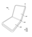
도 1은 본 발명의 실시예들에 따른 표시 장치를 도시한 사시도이다.
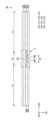
도 2 및 도 3은 도 1의 표시 장치에 포함된 표시 모듈을 설명하기 위한 도면들이다.
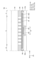
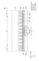
도 4 내지 도 7은 도 2의 A 영역을 확대도시한 단면도들이다.
도 8 및 도 9는 도 1의 표시 장치에 포함된 표시 모듈을 설명하기 위한 도면들이다.
도 10 내지 도 13은 도 8의 B 영역을 확대도시한 단면도들이다.1 is a perspective view showing a display device according to embodiments of the present invention.
FIGS. 2 and 3 are diagrams for explaining a display module included in the display device of FIG. 1 .
Figures 4 to 7 are enlarged cross-sectional views of area A of Figure 2.
FIGS. 8 and 9 are diagrams for explaining a display module included in the display device of FIG. 1 .
Figures 10 to 13 are enlarged cross-sectional views of area B in Figure 8.
이하, 첨부한 도면들을 참조하여, 본 발명의 실시예들에 따른 표시 모듈을 보다 상세하게 설명한다. 첨부된 도면들 상의 동일한 구성 요소들에 대해서는 동일하거나 유사한 참조 부호들을 사용한다.Hereinafter, a display module according to embodiments of the present invention will be described in more detail with reference to the attached drawings. Identical or similar reference numerals are used for identical components in the attached drawings.
도 1은 본 발명의 실시예들에 따른 표시 장치를 도시한 사시도이다.1 is a perspective view showing a display device according to embodiments of the present invention.
도 1을 참조하면, 표시 장치(1000)는 표시 영역(DA) 및 주변 영역(SA)을 포함할 수 있다.Referring to FIG. 1 , the
표시 영역(DA)은 영상을 표시하는 영역일 수 있다. 보다 상세하게는, 표시 장치(1000)는 표시 영역(DA)에 배치되는 복수의 화소들을 포함할 수 있으며, 상기 복수의 화소들 각각은 빛을 방출할 수 있다. 표시 장치(1000)는 상기 복수의 화소들에서 방출되는 빛을 조합함으로써 영상을 표시할 수 있다.The display area DA may be an area that displays an image. More specifically, the
주변 영역(SA)은 표시 영역(DA)의 적어도 일 측에 인접할 수 있다. 예를 들어, 도 1에 도시된 바와 같이, 주변 영역(SA)은 표시 영역(DA)을 둘러쌀 수 있다. 표시 장치(1000)는 주변 영역(SA)에 배치되는 구동 회로를 포함할 수 있으며, 상기 구동 회로는 상기 복수의 화소들에 구동 신호를 제공할 수 있다.The peripheral area SA may be adjacent to at least one side of the display area DA. For example, as shown in FIG. 1, the peripheral area SA may surround the display area DA. The
일 실시예에 있어서, 표시 영역(DA)은 제1 표시 영역(DA1), 제2 표시 영역(DA2) 및 제3 표시 영역(DA3)으로 구획될 수 있다. 제1 표시 영역(DA1), 제2 표시 영역(DA2) 및 제3 표시 영역(DA3) 각각은 영상을 표시하는 영역일 수 있다.In one embodiment, the display area DA may be divided into a first display area DA1, a second display area DA2, and a third display area DA3. Each of the first display area DA1, second display area DA2, and third display area DA3 may be an area that displays an image.
제1 표시 영역(DA1) 및 제2 표시 영역(DA2)은 서로 이격할 수 있다. 표시 장치(1000)는 제1 표시 영역(DA1)과 제2 표시 영역(DA2)에서 실질적으로 평탄한 면을 가질 수 있다.The first display area DA1 and the second display area DA2 may be spaced apart from each other. The
제3 표시 영역(DA3)은 제1 표시 영역(DA1)과 제2 표시 영역(DA2) 사이에 위치할 수 있다. 이 경우, 표시 장치(1000)는 제3 표시 영역(DA3)에서 반복적으로 접히거나, 펼쳐질 수 있다. 보다 상세하게는, 표시 장치(1000)가 접히는 경우, 제1 표시 영역(DA1)과 제2 표시 영역(DA2)은 서로 마주볼 수 있으며, 제3 표시 영역(DA3)은 일정한 곡률을 갖도록 굴곡질 수 있다. 또한, 표시 장치(1000)가 펼쳐지는 경우, 표시 장치(1000)는 제1 표시 영역(DA1), 제2 표시 영역(DA2) 및 제3 표시 영역(DA3) 각각에서 실질적으로 평탄한 면을 가질 수 있다.The third display area DA3 may be located between the first display area DA1 and the second display area DA2. In this case, the
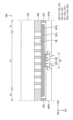
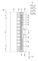
도 2 및 도 3은 도 1의 표시 장치에 포함된 표시 모듈을 설명하기 위한 도면들이다. 도 2는 표시 모듈이 펼쳐진 상태를 도시한 단면도이며, 도 3은 표시 모듈이 접힌 상태를 도시한 단면도이다.FIGS. 2 and 3 are diagrams for explaining a display module included in the display device of FIG. 1 . FIG. 2 is a cross-sectional view showing the display module in an unfolded state, and FIG. 3 is a cross-sectional view showing the display module in a folded state.
도 2 및 도 3을 참조하면, 표시 장치(1000)는 표시 모듈(DM)을 포함할 수 있다. 표시 모듈(DM)은 표시 모듈(DM)을 수납하기 위한 케이스, 표시 모듈(DM)의 반복적인 접힘 및 펼쳐짐을 가이드하기 위한 힌지 부재 등을 포함하는 하우징(미도시) 내에 수납될 수 있다. 이 경우, 상기 하우징과 표시 모듈(DM)은 도 1을 참조하여 설명한 표시 장치(1000)를 구성할 수 있다.Referring to FIGS. 2 and 3 , the
표시 모듈(DM)은 표시부(100), 제1 지지부(200), 접착부(300), 제2 지지부(400) 및 탄성부(500)를 포함할 수 있다.The display module DM may include a
표시부(100)는 복수의 화소들을 포함하는 표시 패널을 포함할 수 있다. 이에 따라, 표시부(100)에서는 영상이 표시될 수 있다. 또한, 일 실시예에 있어서, 표시부(100)는 상기 표시 패널 위(또는, 아래)에 배치되는 다양한 기능층들을 더 포함할 수 있다. 예를 들어, 표시부(100)는 상기 표시 패널 위에 배치되는 편광층, 터치 감지층, 커버 글라스 등을 더 포함할 수 있다. 다른 예를 들면, 표시부(100)는 상기 표시 패널 아래에 배치되는 보호 필름을 더 포함할 수 있다.The
표시부(100)는 제1 영역(A1), 제1 영역(A1)과 이격하는 제2 영역(A2) 및 제1 영역(A1)과 제2 영역(A2) 사이의 폴딩 영역(FA)으로 구획될 수 있다. 제1 영역(A1), 제2 영역(A2) 및 폴딩 영역(FA) 각각에는 상기 복수의 화소들이 배치될 수 있으며, 이에 따라, 제1 영역(A1), 제2 영역(A2) 및 폴딩 영역(FA) 각각에서는 영상이 표시될 수 있다.The
제1 영역(A1)은 표시 장치(1000)의 제1 표시 영역(DA1)에 대응할 수 있으며, 제2 영역(A2)은 표시 장치(1000)의 제2 표시 영역(DA2)에 대응할 수 있다. 또한, 폴딩 영역(FA)은 표시 장치(1000)의 제3 표시 영역(DA3)에 대응할 수 있다. 즉, 표시부(100)는 제1 영역(A1) 및 제2 영역(A2) 각각에서 실질적으로 평탄한 면을 가질 수 있으며, 또한, 폴딩 영역(FA)에서 폴딩 방향(DRF)으로 연장하는 가상의 폴딩 축(FX)을 기준으로 반복적으로 접히거나 펼쳐질 수 있다.The first area A1 may correspond to the first display area DA1 of the
제1 지지부(200)는 표시부(100) 아래에 배치될 수 있다. 제1 지지부(200)는 표시부(100)를 전체적으로 지지할 수 있다. 다시 말하면, 제1 지지부(200)는 제1 영역(A1), 제2 영역(A2) 및 폴딩 영역(FA)에서 표시부(100)를 지지할 수 있다. 표시부(100)를 효과적으로 지지하기 위해, 제1 지지부(200)는 상대적으로 강성이 큰 물질을 포함할 수 있다. 예를 들어, 제1 지지부(200)는 금속 물질을 포함할 수 있다.The
폴딩 영역(FA)에서 표시부(100)가 반복적으로 접히거나 펼쳐지는 경우, 폴딩 영역(FA)과 중첩하는 제1 지지부(200) 또한 반복적으로 접히거나 펼쳐질 수 있다. 이 경우, 일 실시예에 있어서, 폴딩 영역(FA)과 중첩하는 제1 지지부(200)의 플렉서블한 성질을 향상시키기 위해, 폴딩 영역(FA)과 중첩하는 제1 지지부(200)의 강성은 제1 영역(A1) 및 제2 영역(A2)과 중첩하는 제1 지지부(200)의 강성보다 낮을 수 있다. 예를 들어, 제1 지지부(200)는 폴딩 영역(FA)과 중첩하며, 표시부(100)의 두께 방향이며 폴딩 방향(DRF)에 수직한 제1 방향(DR1)으로 형성되는 복수의 그루브들(도 4의 GR)을 정의할 수 있다.When the
접착부(300)는 제1 지지부(200) 아래에 배치될 수 있다. 접착부(300)는 접착력을 갖는 물질을 포함할 수 있다. 예를 들어, 접착부(300)는 PSA 등 접착제를 포함할 수 있다. 접착부(300)는 제1 지지부(200) 아래에 배치되는 구성들(예를 들어, 제2 지지부(400) 및 탄성부(500))에 접착력을 제공할 수 있으며, 이에 따라, 제1 지지부(200) 아래에 배치되는 상기 구성들은 제1 지지부(200) 아래에 부착될 수 있다.The
접착부(300)는 제1 접착부(310), 제2 접착부(320) 및 제3 접착부(330)를 포함할 수 있다.The
제1 접착부(310)는 제1 영역(A1)의 적어도 일부와 중첩할 수 있다. 제2 접착부(320)는 제2 영역(A2)의 적어도 일부와 중첩할 수 있으며, 제2 접착부(320)와 제1 접착부(310)는 서로 이격할 수 있다. 이 경우, 제1 접착부(310) 및 제2 접착부(320) 각각은 폴딩 영역(FA)과는 중첩하지 않을 수 있다.The first
제3 접착부(330)는 제1 접착부(310)과 제2 접착부(320) 사이에 배치될 수 있다. 제3 접착부(330)는 제1 접착층(331) 및 제2 접착층(332)을 포함할 수 있다.The third
제1 접착층(331)은 폴딩 영역(FA) 전체와 중첩할 수 있다. 일 실시예에 있어서, 제1 접착층(331)은 폴딩 영역(FA) 전체와 중첩하며, 폴딩 영역(FA)에 인접한 제1 영역(A1)의 일부 및 폴딩 영역(FA)에 인접한 제2 영역(A2)의 일부와도 중첩할 수 있다.The first
제2 접착층(332)은 제1 접착층(331) 아래에 배치될 수 있다. 제2 접착층(332)은 폴딩 영역(FA)의 일부와 중첩할 수 있다.The second
제2 지지부(400)는 제1 서브 지지부(410) 및 제2 서브 지지부(420)를 포함할 수 있다. 제2 지지부(400)는 상대적으로 강성이 큰 물질을 포함할 수 있다. 예를 들어, 제2 지지부(400)는 금속 물질을 포함할 수 있다.The
제1 서브 지지부(410)는 제1 접착부(310)에 의해 제1 지지부(200) 아래에 접착될 수 있다. 제1 서브 지지부(410)는 실질적으로 평탄한 면을 가질 수 있으며, 제1 영역(A1)의 전체와 중첩할 수 있다. 또한, 상술한 바와 같이, 제1 서브 지지부(410)는 상대적으로 강성이 큰 물질을 포함할 수 있다. 이에 따라, 표시부(100)의 제1 영역(A1)이 제1 서브 지지부(410)에 의해 지지될 수 있으며, 표시 모듈(DM)이 펼쳐지거나(도 2 참조), 또는, 표시 모듈(DM)이 접히더라도(도 3 참조), 제1 서브 지지부(410)에 의해 지지되는 표시부(100)의 제1 영역(A1)은 실질적으로 평탄한 면을 가질 수 있다.The first
일 실시예에 있어서, 제1 서브 지지부(410)는 제1 영역(A1)과 인접한 폴딩 영역(FA)의 일부와도 중첩할 수 있다. 이에 따라, 표시 모듈(DM)이 펼쳐진 상태일 때(도 2 참조), 표시부(100)의 제1 영역(A1)에 인접한 폴딩 영역(FA)의 상기 일부가 제1 서브 지지부(410)에 의해 지지될 수 있다. 즉, 다시 말하면, 표시 모듈(DM)이 펼쳐진 상태일 때(도 2 참조), 제1 서브 지지부(410)에 의해 표시부(100)의 제1 영역(A1)에 인접한 표시부(100)의 폴딩 영역(FA)의 상기 일부가 실질적으로 평탄한 면을 가질 수 있다.In one embodiment, the
제2 서브 지지부(420)는 제2 접착부(320)에 의해 제1 지지부(200) 아래에 접착될 수 있다. 제2 서브 지지부(420)는 실질적으로 평탄한 면을 가질 수 있으며, 제2 영역(A2)의 전체와 중첩할 수 있다. 또한, 상술한 바와 같이, 제2 서브 지지부(420)는 상대적으로 강성이 큰 물질을 포함할 수 있다. 이에 따라, 표시부(100)의 제2 영역(A2)이 제2 서브 지지부(420)에 의해 지지될 수 있으며, 표시 모듈(DM)이 펼쳐지거나(도 2 참조), 또는, 표시 모듈(DM)이 접히더라도(도 3 참조), 제2 서브 지지부(420)에 의해 지지되는 표시부(100)의 제2 영역(A2)은 실질적으로 평탄한 면을 가질 수 있다.The second
일 실시예에 있어서, 제2 서브 지지부(420)는 제2 영역(A2)과 인접한 폴딩 영역(FA)의 일부와도 중첩할 수 있다. 이에 따라, 표시 모듈(DM)이 펼쳐진 상태일 때(도 2 참조), 표시부(100)의 제2 영역(A2)에 인접한 폴딩 영역(FA)의 상기 일부가 제2 서브 지지부(420)에 의해 지지될 수 있다. 즉, 다시 말하면, 표시 모듈(DM)이 펼쳐진 상태일 때(도 2 참조), 제2 서브 지지부(420)에 의해 표시부(100)의 제2 영역(A2)에 인접한 표시부(100)의 폴딩 영역(FA)의 상기 일부가 실질적으로 평탄한 면을 가질 수 있다.In one embodiment, the
제1 서브 지지부(410)와 제2 서브 지지부(420)는 서로 이격할 수 있다. 예를 들어, 도 2에 도시된 바와 같이 표시 모듈(DM)이 펼쳐진 상태일 때, 제2 서브 지지부(420)는 제1 서브 지지부(410)로부터 제1 방향(DR1) 및 폴딩 방향(DRF) 각각에 수직한 제2 방향(DR2)으로 이격할 수 있다. 이 경우, 표시 모듈(DM)이 펼쳐진 상태일 때 제1 서브 지지부(410)와 제2 서브 지지부(420) 사이의 이격 공간은 갭(GP)으로 지칭될 수 있다.The
갭(GP)은 폴딩 영역(FA)의 적어도 일부와 중첩할 수 있다. 이 경우, 도 2에 도시된 바와 같이 표시 모듈(DM)이 펼쳐진 상태일 때, 표시부(100)의 폴딩 영역(FA)에서 갭(GP)과 중첩하는 영역은 제2 지지부(400)에 의해 지지되지 않을 수 있다. 이에 따라, 표시부(100)의 폴딩 영역(FA)에서 갭(GP)과 중첩하는 상기 영역은 외부의 충격에 취약할 수 있다. 예를 들어, 표시 모듈(DM)이 펼쳐진 상태로 표시 장치(1000)를 사용하는 표시 장치(1000)의 사용자는 표시부(100)의 폴딩 영역(FA)에서 갭(GP)과 중첩하는 상기 영역에 터치 입력 등의 압력을 가할 수 있다. 이 경우, 상기 영역에는 상기 압력에 의한 손상(예컨대, 눌림 등)이 발생할 수 있다.The gap GP may overlap at least a portion of the folding area FA. In this case, when the display module DM is in an unfolded state as shown in FIG. 2, the area overlapping the gap GP in the folding area FA of the
상기 손상을 방지하기 위해서, 탄성 물질(예컨대, 고무, PET 등)을 포함하는 탄성부(500)가 제3 접착부(330)에 의해 제1 지지부(200)에 부착될 수 있다. 예를 들어, 일 실시예에 있어서, 탄성부(500)는 제2 접착층(332)에 의해 제1 접착층(331)에 접착될 수 있다. 탄성부(500)는 제1 서브 지지부(410)와 제2 서브 지지부(420) 사이에 배치될 수 있다. 이 경우, 도 2에 도시된 바와 같이 표시 모듈(DM)이 펼쳐진 상태일 때, 탄성부(500)는 제1 서브 지지부(410)에 의해 제2 방향(DR2)에 반대되는 방향으로 가압되며, 제2 서브 지지부(420)에 의해 제2 방향(DR2)으로 가압될 수 있다.In order to prevent the damage, the
이와 같이, 탄성부(500)가 제1 서브 지지부(410) 및 제2 서브 지지부(420)에 의해 가압됨에 따라 탄성부(500)가 압축될 수 있으며, 탄성부(500)의 강성이 증가할 수 있다. 이에 따라, 표시 모듈(DM)이 펼쳐진 상태일 때, 탄성부(500)는 표시부(100)의 폴딩 영역(FA)에서 갭(GP)과 중첩하는 상기 영역을 지지하는 역할을 할 수 있으며, 탄성부(500)에 의해서 상기 손상 발생이 방지될 수 있다.In this way, as the
이와 달리, 도 3에 도시된 바와 같이 표시 모듈(DM)이 접힌 상태일 때, 제1 서브 지지부(410) 및 제2 서브 지지부(420) 각각은 탄성부(500)와 이격할 수 있다. 즉, 다시 말하면, 표시 모듈(DM)이 접힌 상태일 때, 탄성부(500)는 제1 서브 지지부(410) 및 제2 서브 지지부(420)에 의해 가압되지 않을 수 있다.In contrast, when the display module DM is in a folded state as shown in FIG. 3, each of the
이와 같이, 탄성부(500)가 제1 서브 지지부(410) 및 제2 서브 지지부(420)에 의해 가압되지 않음에 따라, 탄성부(500)는 상대적으로 플렉서블한 성질을 가질 수 있다. 이에 따라, 표시 모듈(DM)이 접힌 상태일 때, 탄성부(500)는 폴딩 영역(FA)의 일부에서 일정한 곡률을 갖도록 굴곡질 수 있다.In this way, since the
상술한 바와 같이, 표시 모듈(DM)이 펼쳐진 상태일 때 제1 서브 지지부(410) 및 제2 서브 지지부(420) 각각에 의해 가압되는 탄성부(500)의 밀도는, 표시 모듈(DM)이 접힌 상태일 때의 탄성부(500)의 밀도보다 클 수 있다. 이에 따라, 표시 모듈(DM)이 펼쳐진 상태일 때 탄성부(500)가 표시부(100)를 효과적으로 지지할 수 있도록 상대적으로 큰 강성을 가질 수 있으며, 동시에, 표시 모듈(DM)이 접힌 상태일 때 탄성부(500)는 플렉서블한 성질을 가지게 될 수 있다.As described above, when the display module DM is in an unfolded state, the density of the
이 경우, 일 실시예에 있어서, 표시 모듈(DM)이 펼쳐진 상태일 때 표시부(100)를 효과적으로 지지하기 위해서, 표시 모듈(DM)이 펼쳐진 상태일 때 탄성부(500)의 부피는 표시 모듈(DM)이 접힌 상태일 때의 탄성부(500)의 부피의 약 80% 이하일 수 있다.In this case, in one embodiment, in order to effectively support the
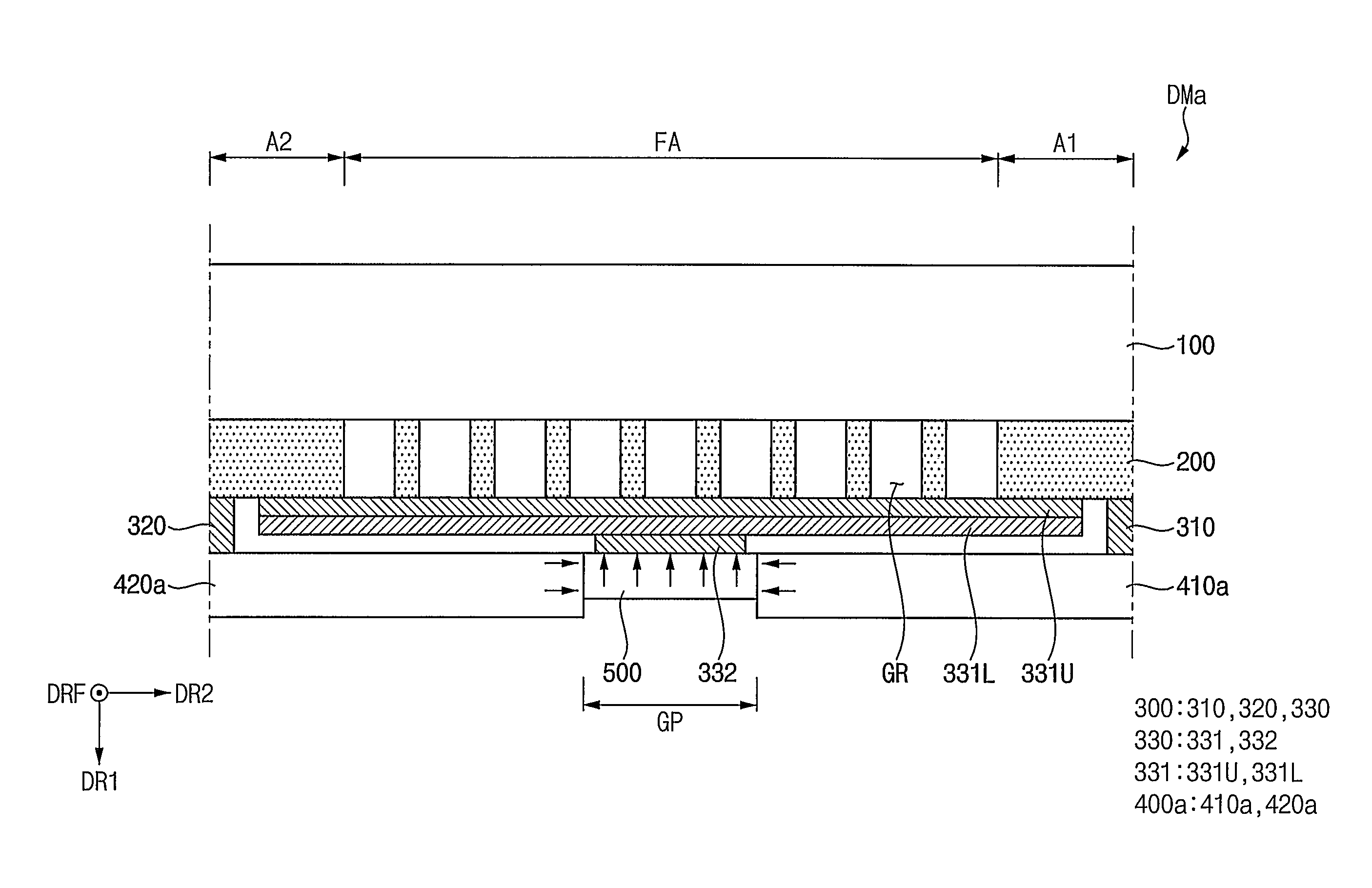
도 4 내지 도 7은 도 2의 A 영역을 확대도시한 단면도들이다. 도 4 내지 도 7은 다양한 실시예들에 따른 제2 지지부(400)를 설명하기 위한 단면도들이다.Figures 4 to 7 are enlarged cross-sectional views of area A of Figure 2. Figures 4 to 7 are cross-sectional views for explaining the
도 1 내지 도 4를 참조하면, 일 실시예에 있어서, 폴딩 영역(FA)과 중첩하는 제1 지지부(200)의 플렉서블한 성질을 향상시키기 위해, 제1 지지부(200)는 폴딩 영역(FA)과 중첩하며 제1 방향(DR1)으로 형성되는 복수의 그루브들(GR)을 정의할 수 있다. 이 경우, 도 4에는, 복수의 그루브들(GR) 각각이 제1 지지부(200)를 관통하는 실시예를 도시하였으나, 복수의 그루브들(GR)의 형상은 이에 제한되지 않는다. 예를 들어, 복수의 그루브들(GR) 각각은 제1 지지부(200)를 완전히 관통하지 않고, 제1 지지부(200)의 일부만을 관통할 수도 있다.Referring to FIGS. 1 to 4 , in one embodiment, in order to improve the flexible properties of the
일 실시예에 있어서, 제1 접착층(331)은 제1 지지부(200)에 정의되는 복수의 그루브들(GR)을 커버할 수 있다. 이에 따라, 제1 접착층(331)은 복수의 그루브들(GR)을 통해 표시부(100)로 이물이 유입되지 않도록 표시부(100)를 보호하는 역할을 할 수 있다.In one embodiment, the first
일 실시예에 있어서, 제1 접착층(331)은 접착 부재(331U) 및 배리어층(331L)을 포함할 수 있다.In one embodiment, the first
접착 부재(331U)는 제1 지지부(200)에 정의되는 복수의 그루브들(GR)을 커버할 수 있으며, 접착 물질을 포함할 수 있다. 이 경우, 상기 접착 물질을 포함하는 접착 부재(331U)는 상기 이물의 유입에 상대적으로 취약할 수 있다. 즉, 다시 말하면, 상기 이물은 접착 부재(331U)를 통과하여 복수의 그루브들(GR)을 통해 표시부(100)로 유입될 수 있다.The
이를 방지하기 위해, 배리어층(331L)은 접착 부재(331U) 아래에 접착될 수 있다. 이 경우, 배리어층(331L)은 접착 부재(331U)의 하면 전체를 커버할 수 있으며, 이에 따라, 배리어층(331L)은 상기 이물의 유입을 방지하는 역할을 할 수 있다. 배리어층(331L)은 플렉서블한 성질을 갖는 무기 절연 물질을 포함할 수 있다.To prevent this, the
도 4에 도시된 바와 같이, 제2 지지부(400a)는 제1 서브 지지부(410a) 및 제2 서브 지지부(420a)를 포함할 수 있으며, 제1 서브 지지부(410a) 및 제2 서브 지지부(420a) 각각은 단면 상 직사각형 형상을 가질 수 있다. 이에 따라, 제1 서브 지지부(410a)는 탄성부(500)를 제2 방향(DR2)에 반대되는 방향으로 가압할 수 있으며, 제2 서브 지지부(420a)는 탄성부(500)를 제2 방향(DR2)으로 가압할 수 있다.As shown in FIG. 4, the second support part 400a may include a first
이 경우, 탄성부(500)의 제2 방향(DR2)으로의 폭은 감소할 수 있으며, 탄성부(500)의 제2 방향(DR2)으로의 상기 폭의 감소량에 비례하여, 탄성부(500)의 제1 방향(DR1)으로의 두께는 증가할 수 있다. 이에 따라, 탄성부(500)는 탄성부(500)와 중첩하는 표시부(100)의 하면을 제1 방향(DR1)에 반대되는 방향으로 가압(즉, 지지)할 수 있다.In this case, the width of the
도 5를 참조하면, 도 4를 참조하여 설명하였던 제2 지지부(400a)와 비교할 때, 도 5에 도시된 제2 지지부(400b)에 포함된 제1 서브 지지부(410b) 및 제2 서브 지지부(420b) 각각은 단면 상 테이퍼진 형상을 가질 수 있다. 보다 상세하게는, 제1 서브 지지부(410b)와 제2 서브 지지부(420b)의 이격 거리는 제1 방향(DR1)으로 갈수록 점진적으로 감소할 수 있다.Referring to FIG. 5, compared to the second support 400a described with reference to FIG. 4, the first sub-support 410b and the second sub-support included in the second support 400b shown in FIG. 5 ( 420b) Each may have a tapered shape in cross section. More specifically, the separation distance between the first sub-support 410b and the second sub-support 420b may gradually decrease in the first direction DR1.
제1 서브 지지부(410b)가 단면 상 테이퍼진 형상을 가짐에 따라, 제1 서브 지지부(410b)는 탄성부(500)를 제2 방향(DR2)에 반대되는 방향으로 가압함과 동시에, 제1 방향(DR1)에 반대되는 방향으로도 가압할 수 있다. 이와 마찬가지로, 제2 서브 지지부(420b)는 탄성부(500)를 제2 방향(DR2)으로 가압함과 동시에, 제1 방향(DR1)에 반대되는 상기 방향으로도 가압할 수 있다.As the first sub-support 410b has a tapered cross-sectional shape, the first sub-support 410b presses the
이에 따라, 도 4를 참조하여 설명하였던 제2 지지부(400a)에 의해 가압되는 탄성부(500)에 비해서, 도 5의 제2 지지부(400b)에 의해 가압되는 탄성부(500)는 표시부(100)를 더 효과적으로 지지할 수 있다.Accordingly, compared to the
도 6을 참조하면, 도 4를 참조하여 설명하였던 제2 지지부(400a)와 비교할 때, 도 6에 도시된 제2 지지부(400c)에 포함된 제1 서브 지지부(410c) 및 제2 서브 지지부(420c) 각각은 돌출부를 더 포함할 수 있다. 보다 상세하게는 제1 서브 지지부(410c)는 제2 서브 지지부(420c)를 향하는 방향(예를 들어, 제2 방향(DR2)에 반대되는 방향)으로 돌출하는 제1 돌출부를 더 포함할 수 있으며, 제2 서브 지지부(420c)는 제1 서브 지지부(410c)를 향하는 방향(예를 들어, 제2 방향(DR2)으로 돌출하는 제2 돌출부를 더 포함할 수 있다.Referring to FIG. 6, compared to the second support 400a described with reference to FIG. 4, the first sub-support 410c and the second sub-support included in the
제1 서브 지지부(410c)가 상기 제1 돌출부를 더 포함함에 따라, 상기 제1 돌출부에 의해 탄성부(500)가 제1 방향(DR1)에 반대되는 방향으로 더 가압될 수 있다. 마찬가지로, 제2 서브 지지부(420c)가 상기 제2 돌출부를 더 포함함에 따라, 상기 제2 돌출부에 의해 탄성부(500)가 제1 방향(DR1)에 반대되는 방향으로 더 가압될 수 있다.As the first sub-support 410c further includes the first protrusion, the
이에 따라, 도 4를 참조하여 설명하였던 제2 지지부(400a)에 의해 가압되는 탄성부(500)에 비해서, 도 6의 제2 지지부(400c)에 의해 가압되는 탄성부(500)는 표시부(100)를 더 효과적으로 지지할 수 있다.Accordingly, compared to the
도 7을 참조하면, 도 4를 참조하여 설명하였던 제2 지지부(400a)와 비교할 때, 도 7에 도시된 제2 지지부(400d)에 포함된 제1 서브 지지부(410b) 및 제2 서브 지지부(420b) 각각은 단면 상 테이퍼진 형상을 가지며 돌출부를 더 포함할 수 있다.Referring to FIG. 7, compared to the second support 400a described with reference to FIG. 4, the first sub-support 410b and the second sub-support included in the second support 400d shown in FIG. 7 ( 420b) Each has a tapered shape in cross section and may further include a protrusion.
보다 상세하게는, 제1 서브 지지부(410d)의 상부와 제2 서브 지지부(420d)의 상부의 이격 거리는 제1 방향(DR1)으로 갈수록 점진적으로 감소할 수 있으며, 제1 서브 지지부(410d)의 상기 상부 아래에 위치하는 제1 서브 지지부(410d)의 하부에는 제2 서브 지지부(420d)를 향하는 방향으로 돌출하는 제1 돌출부가 형성될 수 있고, 제2 서브 지지부(420d)의 상기 상부 아래에 위치하는 제2 서브 지지부(420d)의 하부에는 제1 서브 지지부(410d)를 향하는 방향으로 돌출하는 제2 돌출부가 형성될 수 있다.More specifically, the separation distance between the top of the
이에 따라, 도 4를 참조하여 설명하였던 제2 지지부(400a)에 의해 가압되는 탄성부(500)에 비해서, 도 7의 제2 지지부(400d)에 의해 가압되는 탄성부(500)는 표시부(100)를 더 효과적으로 지지할 수 있다.Accordingly, compared to the
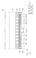
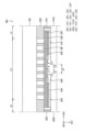
도 8 및 도 9는 도 1의 표시 장치에 포함된 표시 모듈을 설명하기 위한 도면들이다. 도 8은 표시 모듈이 펼쳐진 상태를 도시한 단면도이며, 도 9는 표시 모듈이 접힌 상태를 도시한 단면도이다.FIGS. 8 and 9 are diagrams for explaining a display module included in the display device of FIG. 1 . FIG. 8 is a cross-sectional view showing the display module in an unfolded state, and FIG. 9 is a cross-sectional view showing the display module in a folded state.
도 8 및 도 9를 참조하면, 표시 장치(1000)는 표시 모듈(DM`)을 포함할 수 있다. 표시 모듈(DM`)은 표시 모듈(DM`)을 수납하기 위한 케이스, 표시 모듈(DM`)의 반복적인 접힘 및 펼쳐짐을 가이드하기 위한 힌지 부재 등을 포함하는 하우징(미도시) 내에 수납될 수 있다. 이 경우, 상기 하우징과 표시 모듈(DM`)은 도 1을 참조하여 설명한 표시 장치(1000)를 구성할 수 있다.Referring to FIGS. 8 and 9 , the
표시 모듈(DM`)은 표시부(100`), 제1 지지부(200`), 접착부(300`), 제2 지지부(400`) 및 탄성부(500`)를 포함할 수 있다.The display module DM′ may include a
표시부(100`)는 도 2 및 도 3을 참조하여 설명한 표시부(100)와 실질적으로 동일할 수 있다. 예를 들어, 표시부(100`)는 표시 장치(1000)의 제1 표시 영역(DA1)에 대응하는 제1 영역(A1`), 표시 장치(1000)의 제2 표시 영역(DA2)에 대응하는 제2 영역(A2`) 및 표시 장치(1000)의 제3 표시 영역(DA3)에 대응하는 폴딩 영역(FA`)으로 구획될 수 있으며, 폴딩 영역(FA`)에서 폴딩 방향(DRF)으로 연장하는 가상의 폴딩 축(FX`)을 기준으로 반복적으로 접히거나 펼쳐질 수 있다.The
제1 지지부(200`)는 표시부(100`) 아래에 배치될 수 있다. 제1 지지부(200`)는 도 2 및 도 3을 참조하여 설명하였던 제1 지지부(200)와 실질적으로 동일할 수 있다. 예를 들어, 제1 지지부(200`)는 제1 영역(A1`), 제2 영역(A2`) 및 폴딩 영역(FA`)에서 표시부(100`)를 지지할 수 있다. 또한, 제1 지지부(200`)는 폴딩 영역(FA`)과 중첩하며 제1 방향(DR1)으로 형성되는 복수의 그루브들(도 10의 GR`)을 정의할 수 있다.The
접착부(300`)는 제1 지지부(200`) 아래에 배치될 수 있다. 접착부(300`)는 접착력을 갖는 물질을 포함할 수 있다. 예를 들어, 접착부(300`)는 PSA 등 접착제를 포함할 수 있다. 접착부(300`)는 제1 지지부(200`) 아래에 배치되는 구성들(예를 들어, 제2 지지부(400`) 및 탄성부(500`))에 접착력을 제공할 수 있으며, 이에 따라, 제1 지지부(200`) 아래에 배치되는 상기 구성들은 제1 지지부(200`) 아래에 부착될 수 있다.The
접착부(300`)는 제1 접착부(310`), 제2 접착부(320`) 및 제3 접착부(330`)를 포함할 수 있다.The
제1 접착부(310`)는 도 2 및 도 3을 참조하여 설명한 제1 접착부(310)와 실질적으로 동일할 수 있다. 예를 들어, 제1 접착부(310`)는 제1 영역(A1`)의 적어도 일부와 중첩할 수 있다.The first
제2 접착부(320`)는 도 2 및 도 3을 참조하여 설명한 제2 접착부(320)와 실질적으로 동일할 수 있다. 예를 들어, 제2 접착부(320`)는 제2 영역(A2`)의 적어도 일부와 중첩할 수 있으며, 제2 접착부(320`)와 제1 접착부(310`)는 서로 이격할 수 있다.The second
제3 접착부(330`)는 제1 접착부(310`)와 제2 접착부(320`) 사이에 배치될 수 있다. 일 실시예에 있어서, 제3 접착부(330`)는 복수의 층들을 포함할 수 있다. 제3 접착부(330`)에 포함되는 상기 복수의 층들은 도 10을 참조하여 후술한다.The third
제2 지지부(400`)는 도 2 및 도 3을 참조하여 설명한 제2 지지부(400)와 실질적으로 동일할 수 있다. 예를 들어, 제2 지지부(400`)는 제1 접착부(310`)에 의해 제1 지지부(200`) 아래에 접착되는 제1 서브 지지부(410`) 및 제2 접착부(320`)에 의해 제1 지지부(200`) 아래에 접착되는 제2 서브 지지부(420`)를 포함할 수 있다.The
제1 서브 지지부(410`) 및 제2 서브 지지부(420`) 각각은 실질적으로 평탄한 면을 가질 수 있다. 또한, 제1 서브 지지부(410`)는 제1 영역(A1`)의 전체와 중첩할 수 있으며, 제2 서브 지지부(420`)는 제2 영역(A2`)의 전체와 중첩할 수 있다. 이에 따라, 표시부(100`)의 제1 영역(A1`)은 제1 서브 지지부(410`)에 의해 지지될 수 있으며, 표시부(100`)의 제2 영역(A2`)은 제2 서브 지지부(420`)에 의해 지지될 수 있다. 즉, 표시 모듈(DM`)이 펼쳐지거나(도 8 참조), 또는, 표시 모듈(DM`)이 접히더라도(도 9 참조), 제1 서브 지지부(410`) 및 제2 서브 지지부(420`)에 의해 지지되는 표시부(100`)의 제1 영역(A1`) 및 표시부(100`)의 제2 영역(A2`)은 실질적으로 평탄한 면을 가질 수 있다.Each of the first sub-support 410' and the second sub-support 420' may have a substantially flat surface. Additionally, the
일 실시예에 있어서, 제1 서브 지지부(410`)는 제1 영역(A1`)과 인접한 폴딩 영역(FA`)의 일부와도 중첩할 수 있다. 이에 따라, 표시 모듈(DM`)이 펼쳐진 상태일 때(도 8 참조), 표시부(100`)의 제1 영역(A1`)에 인접한 폴딩 영역(FA`)의 상기 일부가 제1 서브 지지부(410`)에 의해 지지될 수 있다.In one embodiment, the
일 실시예에 있어서, 제2 서브 지지부(420`)는 제2 영역(A2`)과 인접한 폴딩 영역(FA`)의 일부와도 중첩할 수 있다. 이에 따라, 표시 모듈(DM`)이 펼쳐진 상태일 때(도 8 참조), 표시부(100`)의 제2 영역(A2`)에 인접한 폴딩 영역(FA`)의 상기 일부가 제2 서브 지지부(420`)에 의해 지지될 수 있다.In one embodiment, the
제1 서브 지지부(410`)와 제2 서브 지지부(420`)는 서로 이격할 수 있다. 예를 들어, 도 8에 도시된 바와 같이 표시 모듈(DM`)이 펼쳐진 상태일 때, 제2 서브 지지부(420`)는 제1 서브 지지부(410`)로부터 제2 방향(DR2)으로 이격할 수 있다. 이 경우, 표시 모듈(DM`)이 펼쳐진 상태일 때 제1 서브 지지부(410`)와 제2 서브 지지부(420`) 사이의 이격 공간은 갭(GP`)으로 지칭될 수 있다.The first sub-support 410' and the second sub-support 420' may be spaced apart from each other. For example, as shown in FIG. 8, when the display module DM′ is unfolded, the
갭(GP`)은 폴딩 영역(FA`)의 적어도 일부와 중첩할 수 있다. 이 경우, 도 8에 도시된 바와 같이 표시 모듈(DM`)이 펼쳐진 상태일 때, 표시부(100`)의 폴딩 영역(FA`)에서 갭(GP`)과 중첩하는 영역은 제2 지지부(400`)에 의해 지지되지 않을 수 있다. 이에 따라, 폴딩 영역(FA`)에서 갭(GP`)과 중첩하는 상기 영역은 외부의 충격에 취약할 수 있다. 예를 들어, 표시 모듈(DM`)이 펼쳐진 상태로 표시 장치(1000)를 사용하는 표시 장치(1000)의 사용자는 표시부(100`)의 폴딩 영역(FA`)에서 갭(GP`)과 중첩하는 상기 영역에 터치 입력 등의 압력을 가할 수 있다. 이 경우, 상기 영역에는 상기 압력에 의한 손상(예컨대, 눌림 등)이 발생할 수 있다.The gap (GP′) may overlap at least a portion of the folding area (FA′). In this case, as shown in FIG. 8, when the display module DM′ is in an unfolded state, the area overlapping the gap GP′ in the folding area FA′ of the
상기 손상을 방지하기 위해서, 탄성 물질(예컨대, 고무, PET 등)을 포함하는 탄성부(500`)가 제3 접착부(330`)에 의해 제1 지지부(200`)에 부착될 수 있다. 예를 들어, 탄성부(500`)는 제1 서브 지지부(410`)와 제1 지지부(200`) 사이에서 제3 접착부(330`)에 의해 제1 지지부(200`)에 접착되는 제1 고정부(510`), 제2 서브 지지부(420`)와 제1 지지부(200`) 사이에서 제3 접착부(330`)에 의해 제1 지지부(200`)에 접착되며 제1 고정부(510`)와 이격하는 제2 고정부(520`)를 포함할 수 있다.In order to prevent the damage, the
또한, 도 8에 도시된 바와 같이 표시 모듈(DM`)이 펼쳐진 상태일 때, 탄성부(500`)는 제1 서브 지지부(410`)와 제2 서브 지지부(420`)에 의해 가압될 수 있다. 예를 들어, 탄성부(500`)는 제1 고정부(510`)와 제2 고정부(520`) 사이에서 제1 고정부(510`)와 제2 고정부(520`)를 연결하는 비고정부(530`)를 포함할 수 있다. 이 경우, 비고정부(530`)는 제1 고정부(510`)와 제2 고정부(520`) 사이에서 제3 접착부(330`)에 접착되지 않는 탄성부(500`)의 일부분으로 정의될 수 있다. 이에 따라, 표시 모듈(DM`)이 펼쳐진 상태일 때 비고정부(530`)는 제1 서브 지지부(410`)에 의해 제2 방향(DR2)에 반대되는 방향으로 가압되며, 제2 서브 지지부(420`)에 의해 제2 방향(DR2)으로 가압될 수 있다.In addition, as shown in FIG. 8, when the display module DM′ is in an unfolded state, the
이와 같이, 비고정부(530`)가 제1 서브 지지부(410`) 및 제2 서브 지지부(410`)에 의해 가압됨에 따라, 비고정부(530`)가 압축될 수 있으며 비고정부(530`)의 강성이 증가할 수 있다. 이에 따라, 표시 모듈(DM`)이 펼쳐진 상태일 때, 비고정부(530`)는 표시부(100`)의 폴딩 영역(FA`)에서 갭(GP`)과 중첩하는 상기 영역을 지지하는 역할을 할 수 있다.In this way, as the
이와 달리, 도 9에 도시된 바와 같이 표시 모듈(DM`)이 접힌 상태일 때, 제1 서브 지지부(410`) 및 제2 서브 지지부(420`) 각각은 비고정부(530`)와 이격할 수 있다. 즉, 다시 말하면, 표시 모듈(DM`)이 접힌 상태일 때 비고정부(530`)는 제1 서브 지지부(410`) 및 제2 서브 지지부(420`)에 의해 가압되지 않을 수 있다.In contrast, when the display module DM′ is in a folded state as shown in FIG. 9, each of the
이와 같이, 비고정부(530`)가 제1 서브 지지부(410`) 및 제2 서브 지지부(420`)에 의해 가압되지 않음에 따라, 비고정부(530`)는 상대적으로 플렉서블한 성질을 가질 수 있다. 이 경우, 일 실시예에 있어서, 도 9에 도시된 바와 같이 표시 모듈(DM`)이 접힌 상태일 때 비고정부(530`)의 일부는 제3 접착부(330`)와 이격하며 굴곡진 형상을 가질 수 있다.In this way, as the non-fixed portion 530' is not pressed by the first sub-support 410' and the second sub-support 420', the non-fixed portion 530' can have relatively flexible properties. there is. In this case, in one embodiment, when the display module DM′ is in a folded state as shown in FIG. 9, a portion of the
상술한 바와 같이, 표시 모듈(DM`)이 펼쳐진 상태일 때 제1 서브 지지부(410`) 및 제2 서브 지지부(420`) 각각에 의해 가압되는 비고정부(530`)의 밀도는, 표시 모듈(DM`)이 접힌 상태일 때의 비고정부(530`)의 밀도보다 클 수 있다. 이에 따라, 표시 모듈(DM`)이 펼쳐진 상태일 때 비고정부(530`)가 표시부(100`)를 효과적으로 지지할 수 있도록 상대적으로 큰 강성을 가질 수 있으며, 동시에, 표시 모듈(DM`)이 접힌 상태일 때 비고정부(530`)는 플렉서블한 성질을 가지게 될 수 있다.As described above, when the display module DM′ is in an unfolded state, the density of the
이 경우, 일 실시예에 있어서, 표시 모듈(DM`)이 펼쳐진 상태일 때 표시부(100`)를 효과적으로 지지하기 위해서, 표시 모듈(DM`)이 펼쳐진 상태일 때 비고정부(530`)의 부피는 표시 모듈(DM`)이 접힌 상태일 때의 비고정부(530`)의 부피의 약 80% 이하일 수 있다.In this case, in one embodiment, in order to effectively support the
일 실시예에 있어서, 도 8 및 도 9에 도시된 바와 같이, 표시 모듈(DM`)이 접히거나, 또는 펼쳐지는 경우에도, 제1 고정부(510`)는 제1 서브 지지부(410`)의 상면과 직접 접촉할 수 있으며, 제2 고정부(520`)는 제2 서브 지지부(420`)의 상면과 직접 접촉할 수 있다.In one embodiment, as shown in FIGS. 8 and 9, even when the display module DM′ is folded or unfolded, the
도 10 내지 도 13은 도 8의 B 영역을 확대도시한 단면도들이다. 도 10 내지 도 13은 다양한 실시예들에 따른 제2 지지부(400`)를 설명하기 위한 단면도들이다.Figures 10 to 13 are enlarged cross-sectional views of area B in Figure 8. 10 to 13 are cross-sectional views for explaining the
도 1, 도 8, 도 9 및 도 10을 참조하면, 일 실시예에 있어서, 폴딩 영역(FA`)과 중첩하는 제1 지지부(200`)의 플렉서블한 성질을 향상시키기 위해, 제1 지지부(200`)는 폴딩 영역(FA`)과 중첩하며 제1 방향(DR1)으로 형성되는 복수의 그루브들(GR`)을 정의할 수 있다. 이 경우, 도 10에는, 복수의 그루브들(GR`) 각각이 제1 지지부(200`)를 관통하는 실시예를 도시하였으나, 복수의 그루브들(GR`)의 형상은 이에 제한되지 않는다. 예를 들어, 복수의 그루브들(GR`) 각각은 제1 지지부(200`)를 완전히 관통하지 않고, 제1 지지부(200`)의 일부만을 관통할 수도 있다.Referring to FIGS. 1, 8, 9, and 10, in one embodiment, in order to improve the flexible properties of the
일 실시예에 있어서, 제3 접착부(330`)는 제1 접착층(331`), 배리어층(332`), 제1 서브 접착층(333`) 및 제2 서브 접착층(334`)을 포함할 수 있다.In one embodiment, the third
제1 접착층(331`)은 제1 지지부(200`)에 의해 정의되는 복수의 그루브들(GR`)을 커버할 수 있으며, 접착 물질을 포함할 수 있다. 이 경우, 상기 접착 물질을 포함하는 제1 접착층(331`)은 이물의 유입에 상대적으로 취약할 수 있다. 즉, 다시 말하면, 상기 이물은 제1 접착층(331`)을 통과하여 복수의 그루브들(GR`)을 통해 표시부(100`)로 유입될 수 있다.The first
이를 방지하기 위해, 배리어층(332`)은 제1 접착층(331`) 아래에 접착될 수 있으며, 제1 접착층(331`)의 하면 전체를 커버할 수 있다. 이에 따라, 배리어층(332`)은 상기 이물의 유입을 방지하는 역할을 할 수 있다. 배리어층(332`)은 플렉서블한 성질을 갖는 무기 절연 물질을 포함할 수 있다.To prevent this, the barrier layer 332' may be adhered below the first adhesive layer 331' and may cover the entire lower surface of the first adhesive layer 331'. Accordingly, the barrier layer 332' may serve to prevent the inflow of foreign substances. The
제1 서브 접착층(333`)은 배리어층(332`) 아래에 접착될 수 있다. 제1 서브 접착층(333`)은 제1 고정부(510`)를 배리어층(332`)에 접착하는 역할을 할 수 있다. 이 경우, 제1 서브 접착층(333`)은 도 10에 도시된 바와 같이 표시 모듈(DMa`)이 펼쳐진 상태일 때 제1 서브 지지부(410a`)와 표시부(100`) 사이에 배치될 수 있다.The first sub-adhesive layer 333' may be adhered below the barrier layer 332'. The first sub-adhesive layer 333' may serve to adhere the first fixing part 510' to the barrier layer 332'. In this case, the first
제2 서브 접착층(334`)은 배리어층(332`) 아래에 접착될 수 있으며, 제1 서브 접착층(333`)과 이격할 수 있다. 제2 서브 접착층(334`)은 제2 고정부(520`)를 배리어층(332`)에 접착하는 역할을 할 수 있다. 이 경우, 제2 서브 접착층(334`)은 도 10에 도시된 바와 같이 표시 모듈(DMa`)이 펼쳐진 상태일 때 제2 서브 지지부(420a`)와 표시부(100`) 사이에 배치될 수 있다.The second sub-adhesive layer 334' may be adhered below the barrier layer 332' and may be spaced apart from the first sub-adhesive layer 333'. The second
도 4에 도시된 바와 같이, 제2 지지부(400a`)는 제1 서브 지지부(410a`) 및 제2 서브 지지부(420a`)를 포함할 수 있으며, 제1 서브 지지부(410a`) 및 제2 서브 지지부(420a`) 각각은 단면 상 직사각형 형상을 가질 수 있다. 이에 따라, 제1 서브 지지부(410a`)는 비고정부(530`)를 제2 방향(DR2)에 반대되는 방향으로 가압할 수 있으며, 제2 서브 지지부(420a`)는 비고정부(530`)를 제2 방향(DR2)으로 가압할 수 있다. 이에 따라, 비고정부(530`)는, 제1 서브 지지부(410a`) 및 제2 서브 지지부(420a`)에 의해 압축될 수 있으며, 제1 서브 접착층(333`)과 제2 서브 접착층(334`) 사이에서 배리어층(332`)의 하면을 가압함으로써 표시부(100`)의 하면을 제1 방향(DR1)에 반대되는 방향으로 가압(즉, 지지)할 수 있다.As shown in FIG. 4, the second support portion 400a′ may include a first
도 11을 참조하면, 도 10을 참조하여 설명하였던 제2 지지부(400a`)와 비교할 때, 도 10에 도시된 제2 지지부(400b`)에 포함된 제1 서브 지지부(410b`) 및 제2 서브 지지부(420b`) 각각은 단면 상 테이퍼진 형상을 가질 수 있다. 보다 상세하게는, 제1 서브 지지부(410b`)와 제2 서브 지지부(420b`)의 이격 거리는 제1 방향(DR1)으로 갈수록 점진적으로 감소할 수 있다.Referring to Figure 11, compared to the second support part 400a' described with reference to Figure 10, the first
제1 서브 지지부(410b`)가 단면 상 테이퍼진 형상을 가짐에 따라, 제1 서브 지지부(410b`)는 비고정부(530`)를 제2 방향(DR2)에 반대되는 방향으로 가압함과 동시에, 제1 방향(DR1)에 반대되는 방향으로도 가압할 수 있다. 이와 마찬가지로, 제2 서브 지지부(420b`)는 비고정부(530`)를 제2 방향(DR2)으로 가압함과 동시에, 제1 방향(DR1)에 반대되는 방향으로도 가압할 수 있다.As the first sub-support 410b' has a tapered cross-sectional shape, the first sub-support 410b' presses the non-fixed portion 530' in a direction opposite to the second direction DR2. , pressure can also be applied in a direction opposite to the first direction DR1. Likewise, the second
이에 따라, 도 10을 참조하여 설명하였던 제2 지지부(400a`)에 의해 가압되는 비고정부(530`)에 비해서, 도 11의 제2 지지부(400b`)에 의해 가압되는 비고정부(530`)는 표시부(100`)를 더 효과적으로 지지할 수 있다.Accordingly, compared to the
도 12를 참조하면, 도 10을 참조하여 설명하였던 제2 지지부(400a`)와 비교할 때, 도 12에 도시된 제2 지지부(400c`)에 포함된 제1 서브 지지부(410c`) 및 제2 서브 지지부(420c`) 각각은 돌출부를 더 포함할 수 있다. 보다 상세하게는, 제1 서브 지지부(410c`)는 제2 서브 지지부(420c`)를 향하는 방향(예를 들어, 제2 방향(DR2)에 반대되는 방향)으로 돌출하는 제1 돌출부를 더 포함할 수 있으며, 제2 서브 지지부(420c`)는 제1 서브 지지부(410c`)를 향하는 방향(예를 들어, 제2 방향(DR2))으로 돌출하는 제2 돌출부를 더 포함할 수 있다.Referring to FIG. 12, when compared to the second support 400a′ described with reference to FIG. 10, the first sub-support 410c′ and the second sub-support 410c′ included in the
제1 서브 지지부(410c`)가 상기 제1 돌출부를 더 포함함에 따라, 상기 제1 돌출부에 의해 비고정부(530`)가 제1 방향(DR1)에 반대되는 방향으로 더 가압될 수 있다. 마찬가지로, 제2 서브 지지부(420c`)가 상기 제2 돌출부를 더 포함함에 따라, 상기 제2 돌출부에 의해 비고정부(530`)가 제1 방향(DR1)에 반대되는 방향으로 더 가압될 수 있다.As the first sub-support 410c' further includes the first protrusion, the non-fixed portion 530' may be further pressed in a direction opposite to the first direction DR1 by the first protrusion. Likewise, as the second
이에 따라, 도 10을 참조하여 설명하였던 제2 지지부(400a`)에 의해 가압되는 비고정부(530`)에 비해서, 도 12의 제2 지지부(400c`)에 의해 가압되는 비고정부(530`)는 표시부(100`)를 더 효과적으로 지지할 수 있다.Accordingly, compared to the
도 13을 참조하면, 도 10을 참조하여 설명하였던 제2 지지부(400a`)와 비교할 때, 도 13에 도시된 제2 지지부(400d`)에 포함된 제1 서브 지지부(410d`) 및 제2 서브 지지부(420d`) 각각은 단면 상 테이퍼진 형상을 가지며, 돌출부를 더 포함할 수 있다.Referring to Figure 13, compared to the second support part 400a' explained with reference to Figure 10, the first
보다 상세하게는, 제1 서브 지지부(410d`)의 상부와 제2 서브 지지부(420d`)의 상부의 이격 거리는 제1 방향(DR1)으로 갈수록 점진적으로 감소할 수 있으며, 제1 서브 지지부(410d`)의 상기 상부 아래에 위치하는 제1 서브 지지부(410d`)의 하부에는 제2 서브 지지부(420d`)를 향하는 방향으로 돌출하는 제1 돌출부가 형성될 수 있고, 제2 서브 지지부(420d`)의 상기 상부 아래에 위치하는 제2 서브 지지부(420d`)의 하부에는 제1 서브 지지부(410d`)를 향하는 방향으로 돌출하는 제2 돌출부가 형성될 수 있다.More specifically, the separation distance between the upper part of the first sub-support 410d' and the upper part of the second sub-support 420d' may gradually decrease in the first direction DR1, and the first sub-support 410d A first protrusion protruding in a direction toward the
이에 따라, 도 10을 참조하여 설명하였던 제2 지지부(400a`)에 의해 가압되는 비고정부(530`)에 비해서, 도 13의 제2 지지부(400d`)에 의해 가압되는 비고정부(530`)는 표시부(100`)를 더 효과적으로 지지할 수 있다.Accordingly, compared to the
이상에서는, 본 발명의 예시적인 실시예들을 참조하여 설명하였지만, 해당 기술 분야에서 통상의 지식을 가진 자라면 하기의 특허 청구 범위에 기재된 본 발명의 사상 및 영역으로부터 벗어나지 않는 범위 내에서 본 발명을 다양하게 수정 및 변경시킬 수 있음을 이해할 것이다.In the above, the present invention has been described with reference to exemplary embodiments, but those skilled in the art can vary the present invention without departing from the spirit and scope of the present invention as set forth in the following patent claims. You will understand that it can be modified and changed.
본 발명은 표시 모듈 및 이를 포함하는 전자 기기에 적용될 수 있다. 예를 들어, 본 발명은 스마트폰, 스마트패드, 스마트 워치, 태블릿 PC, 차량용 네비게이션 시스템, 텔레비전, 컴퓨터 모니터 등에 적용될 수 있다.The present invention can be applied to display modules and electronic devices including the same. For example, the present invention can be applied to smartphones, smart pads, smart watches, tablet PCs, vehicle navigation systems, televisions, computer monitors, etc.
1000: 표시 장치
DM, DM`: 표시 모듈
A1, A1`: 제1 영역
A2, A2`: 제2 영역
FA, FA`: 폴딩 영역
100, 100`: 표시부
200, 200`: 제1 지지부
300, 300`: 접착부
400, 400`: 제2 지지부
500, 500`: 탄성부1000: Display device DM, DM`: Display module
A1, A1`: First area A2, A2`: Second area
FA, FA`:
200, 200`:
400, 400`:
Claims (20)
상기 표시부 아래에 배치되며, 상기 제1 영역, 상기 제2 영역 및 상기 폴딩 영역에서 상기 표시부를 지지하는 제1 지지부;
상기 제1 지지부 아래에 배치되며, 상기 표시부의 상기 제1 영역을 지지하는 제1 서브 지지부 및 상기 표시부의 상기 제2 영역을 지지하며 상기 제1 서브 지지부와 이격하는 제2 서브 지지부를 포함하는 제2 지지부; 및
상기 제1 서브 지지부와 상기 제2 서브 지지부 사이에 배치되며, 상기 표시부가 펼쳐진 상태에서 상기 제1 서브 지지부 및 상기 제2 서브 지지부 각각에 의해 압축됨으로써 상기 표시부의 상기 폴딩 영역을 지지하는 탄성부를 포함하는 표시 모듈.a display unit including a first area, a second area spaced apart from the first area, and a folding area between the first area and the second area;
a first support part disposed below the display unit and supporting the display unit in the first area, the second area, and the folding area;
a first sub-support disposed below the first support, supporting the first area of the display, and a second sub-support supporting the second area of the display and being spaced apart from the first sub-support. 2 support portion; and
An elastic part is disposed between the first sub-support and the second sub-support and supports the folding area of the display by being compressed by each of the first and second sub-supports when the display is unfolded. display module.
상기 제1 서브 지지부와 상기 제1 지지부 사이에 배치되며, 상기 제1 서브 지지부와 상기 제1 지지부를 서로 접착시키는 제1 접착부;
상기 제2 서브 지지부와 상기 제1 지지부 사이에 배치되며, 상기 제2 서브 지지부와 상기 제1 지지부를 서로 접착시키는 제2 접착부; 및
상기 제1 접착부와 상기 제2 접착부 사이에 배치되며, 상기 제1 지지부와 상기 탄성부를 서로 접착시키는 제3 접착부를 포함하는 것을 특징으로 하는 표시 모듈.According to paragraph 1,
a first adhesive portion disposed between the first sub support portion and the first support portion, and bonding the first sub support portion and the first support portion to each other;
a second adhesive part disposed between the second sub support part and the first support part and adhering the second sub support part and the first support part to each other; and
A display module comprising a third adhesive portion disposed between the first adhesive portion and the second adhesive portion and bonding the first support portion and the elastic portion to each other.
상기 제1 지지부 아래에 배치되며, 상기 폴딩 영역 전체와 중첩하는 접착 부재 및 상기 접착 부재 아래에 배치되며, 상기 폴딩 영역 전체와 중첩하는 배리어층을 포함하는 제1 접착층; 및
상기 배리어층 아래에 배치되며, 상기 배리어층과 상기 탄성부를 서로 접착시키는 제2 접착층을 포함하는 것을 특징으로 하는 표시 모듈.The method of claim 3, wherein the third adhesive portion is:
a first adhesive layer disposed below the first support portion and including an adhesive member overlapping the entire folding area and a barrier layer disposed below the adhesive member and overlapping the entire folding area; and
A display module comprising a second adhesive layer disposed below the barrier layer and adhering the barrier layer and the elastic portion to each other.
상기 폴딩 영역과 중첩하며, 상기 표시부의 두께 방향으로 형성되는 복수의 그루브들을 정의하는 것을 특징으로 하는 표시 모듈.The method of claim 1, wherein the first support unit,
A display module that overlaps the folding area and defines a plurality of grooves formed in the thickness direction of the display unit.
상기 제1 서브 지지부는 상기 표시부가 펼쳐진 상태에서 상기 제2 서브 지지부를 향하는 방향으로 돌출하여, 상기 탄성부의 하면을 가압하는 제1 돌출부를 더 포함하며,
상기 제2 서브 지지부는 상기 표시부가 펼쳐진 상태에서 상기 제1 서브 지지부를 향하는 방향으로 돌출하여, 상기 탄성부의 상기 하면을 가압하는 제2 돌출부를 더 포함하는 것을 특징으로 하는 표시 모듈.According to paragraph 1,
The first sub-support further includes a first protrusion that protrudes in a direction toward the second sub-support when the display unit is unfolded and presses a lower surface of the elastic unit,
The display module further includes a second protrusion that protrudes in a direction toward the first sub supporter when the display unit is unfolded and presses the lower surface of the elastic unit.
상기 표시부의 하면으로부터 멀어지는 방향으로 갈수록 점진적으로 감소하는 것을 특징으로 하는 표시 모듈.The method of claim 1, wherein in a cross-sectional view when the display unit is unfolded, the separation distance between the first sub support unit and the second sub support unit is:
The display module is characterized in that it gradually decreases in a direction away from the lower surface of the display unit.
상기 표시부가 펼쳐진 상태에서 상기 제1 서브 지지부는 상기 표시부의 상기 제1 영역 전체와 중첩하며,
상기 표시부가 펼쳐진 상태에서 상기 제2 서브 지지부는 상기 표시부의 상기 제2 영역 전체와 중첩하는 것을 특징으로 하는 표시 모듈.According to paragraph 1,
When the display unit is unfolded, the first sub support portion overlaps the entire first area of the display unit,
A display module, wherein when the display unit is unfolded, the second sub support portion overlaps the entire second area of the display unit.
상기 표시부가 접힌 상태에서 상기 탄성부의 밀도보다 큰 것을 특징으로 하는 표시 모듈.The method of claim 1, wherein the density of the elastic portion when the display portion is unfolded is:
A display module, wherein the display unit has a density greater than that of the elastic unit in a folded state.
상기 표시부가 접힌 상태에서 상기 탄성부의 부피의 80% 이하인 것을 특징으로 하는 표시 모듈.The method of claim 1, wherein when the display unit is unfolded, the volume of the elastic unit is:
A display module, wherein the display portion is 80% or less of the volume of the elastic portion when the display portion is folded.
상기 표시부 아래에 배치되며, 상기 제1 영역, 상기 제2 영역 및 상기 폴딩 영역에서 상기 표시부를 지지하는 제1 지지부;
상기 제1 지지부 아래에 배치되며, 상기 표시부의 상기 제1 영역을 지지하는 제1 서브 지지부 및 상기 표시부의 상기 제2 영역을 지지하며 상기 제1 서브 지지부와 이격하는 제2 서브 지지부를 포함하는 제2 지지부; 및
상기 제1 서브 지지부와 상기 제1 지지부 사이에서 상기 제1 지지부에 접착되는 제1 고정부, 상기 제2 서브 지지부와 상기 제1 지지부 사이에서 상기 제1 지지부에 접착되는 제2 고정부 및 상기 제1 고정부와 상기 제2 고정부를 연결하며, 상기 표시부가 펼쳐진 상태에서 상기 제1 서브 지지부 및 상기 제2 서브 지지부 각각에 의해 압축됨으로써 상기 표시부의 상기 폴딩 영역을 지지하는 비고정부를 포함하는 탄성부를 구비한, 표시 모듈.a display unit including a first area, a second area spaced apart from the first area, and a folding area between the first area and the second area;
a first support part disposed below the display unit and supporting the display unit in the first area, the second area, and the folding area;
a first sub-support disposed below the first support, supporting the first area of the display, and a second sub-support supporting the second area of the display and being spaced apart from the first sub-support. 2 support portion; and
A first fixing part attached to the first support between the first sub support and the first support, a second fixing part attached to the first support between the second sub support and the first support, and the first fixing part attached to the first support. 1 Elasticity including a non-fixing part that connects the fixing part and the second fixing part and supports the folding area of the display unit by being compressed by each of the first sub support part and the second sub support part when the display part is unfolded. A display module, including:
상기 폴딩 영역과 중첩하며, 상기 표시부의 두께 방향으로 형성되는 복수의 그루브들을 정의하는 것을 특징으로 하는 표시 모듈.The method of claim 11, wherein the first support unit,
A display module that overlaps the folding area and defines a plurality of grooves formed in the thickness direction of the display unit.
상기 제1 서브 지지부는 상기 표시부가 펼쳐진 상태에서 상기 제2 서브 지지부를 향하는 방향으로 돌출하여, 상기 탄성부의 하면을 가압하는 제1 돌출부를 더 포함하며,
상기 제2 서브 지지부는 상기 표시부가 펼쳐진 상태에서 상기 제1 서브 지지부를 향하는 방향으로 돌출하여, 상기 탄성부의 상기 하면을 가압하는 제2 돌출부를 더 포함하는 것을 특징으로 하는 표시 모듈.According to clause 11,
The first sub-support further includes a first protrusion that protrudes in a direction toward the second sub-support when the display unit is unfolded and presses a lower surface of the elastic unit,
The display module further includes a second protrusion that protrudes in a direction toward the first sub supporter when the display unit is unfolded and presses the lower surface of the elastic unit.
상기 표시부의 하면으로부터 멀어지는 방향으로 갈수록 점진적으로 감소하는 것을 특징으로 하는 표시 모듈.The method of claim 11, wherein in a cross-sectional view when the display unit is unfolded, the separation distance between the first sub support unit and the second sub support unit is:
The display module is characterized in that it gradually decreases in a direction away from the lower surface of the display unit.
상기 표시부가 펼쳐진 상태에서 상기 제1 서브 지지부는 상기 표시부의 상기 제1 영역 전체와 중첩하며,
상기 표시부가 펼쳐진 상태에서 상기 제2 서브 지지부는 상기 표시부의 상기 제2 영역 전체와 중첩하는 것을 특징으로 하는 표시 모듈.According to clause 11,
When the display unit is unfolded, the first sub support portion overlaps the entire first area of the display unit,
A display module, wherein when the display unit is unfolded, the second sub support portion overlaps the entire second area of the display unit.
상기 표시부가 접힌 상태에서 상기 비고정부의 밀도보다 큰 것을 특징으로 하는 표시 모듈.The method of claim 11, wherein the density of the non-fixed portion when the display portion is unfolded is:
A display module, wherein the display unit has a density greater than that of the non-fixed unit in a folded state.
상기 표시부가 접힌 상태에서 상기 비고정부의 부피의 80% 이하인 것을 특징으로 하는 표시 모듈.The method of claim 11, wherein when the display unit is unfolded, the volume of the non-fixed unit is:
A display module, wherein the display portion is 80% or less of the volume of the non-fixed portion in a folded state.
상기 제1 고정부는 상기 제1 서브 지지부의 상면과 직접 접촉하며,
상기 제2 고정부는 상기 제2 서브 지지부의 상면과 직접 접촉하는 것을 특징으로 하는 표시 모듈.According to clause 11,
The first fixing part directly contacts the upper surface of the first sub support part,
The display module, wherein the second fixing part directly contacts the upper surface of the second sub support part.
상기 제1 지지부 아래에 배치되며, 상기 폴딩 영역 전체와 중첩하는 제1 접착층;
상기 제1 접착층 아래에 배치되며, 상기 폴딩 영역 전체와 중첩하는 배리어층;
상기 배리어층 아래에 배치되며, 상기 배리어층과 상기 제1 고정부를 서로 접착시키는 제1 서브 접착층 및 상기 배리어층과 상기 제2 고정부를 서로 접착시키며 상기 제1 서브 접착층과 이격하는 제2 서브 접착층을 포함하는 제2 접착층을 포함하는 것을 특징으로 하는 표시 모듈.According to clause 11,
a first adhesive layer disposed below the first support part and overlapping the entire folding area;
a barrier layer disposed below the first adhesive layer and overlapping the entire folding area;
A first sub adhesive layer disposed below the barrier layer and adhering the barrier layer and the first fixing part to each other, and a second sub adhesive layer that adheres the barrier layer and the second fixing part to each other and is spaced apart from the first sub adhesive layer. A display module comprising a second adhesive layer including an adhesive layer.
Priority Applications (7)
| Application Number | Priority Date | Filing Date | Title |
|---|---|---|---|
| KR1020220137508A KR20240057504A (en) | 2022-10-24 | 2022-10-24 | Display module |
| US18/365,092 US12393234B2 (en) | 2022-10-24 | 2023-08-03 | Display module |
| EP23883026.9A EP4610967A1 (en) | 2022-10-24 | 2023-10-23 | Display module |
| JP2025517671A JP2025535233A (en) | 2022-10-24 | 2023-10-23 | Display Module |
| PCT/KR2023/016453 WO2024090920A1 (en) | 2022-10-24 | 2023-10-23 | Display module |
| CN202311384047.8A CN117935678A (en) | 2022-10-24 | 2023-10-24 | Display Module |
| CN202322858242.1U CN221200671U (en) | 2022-10-24 | 2023-10-24 | Display Module |
Applications Claiming Priority (1)
| Application Number | Priority Date | Filing Date | Title |
|---|---|---|---|
| KR1020220137508A KR20240057504A (en) | 2022-10-24 | 2022-10-24 | Display module |
Publications (1)
| Publication Number | Publication Date |
|---|---|
| KR20240057504A true KR20240057504A (en) | 2024-05-03 |
Family
ID=90768974
Family Applications (1)
| Application Number | Title | Priority Date | Filing Date |
|---|---|---|---|
| KR1020220137508A Pending KR20240057504A (en) | 2022-10-24 | 2022-10-24 | Display module |
Country Status (6)
| Country | Link |
|---|---|
| US (1) | US12393234B2 (en) |
| EP (1) | EP4610967A1 (en) |
| JP (1) | JP2025535233A (en) |
| KR (1) | KR20240057504A (en) |
| CN (2) | CN117935678A (en) |
| WO (1) | WO2024090920A1 (en) |
Cited By (1)
| Publication number | Priority date | Publication date | Assignee | Title |
|---|---|---|---|---|
| WO2026079700A1 (en) * | 2024-10-07 | 2026-04-16 | 삼성전자주식회사 | Display module comprising support plate, and foldable electronic device comprising same |
Families Citing this family (1)
| Publication number | Priority date | Publication date | Assignee | Title |
|---|---|---|---|---|
| US20260007027A1 (en) * | 2024-06-26 | 2026-01-01 | Samsung Display Co., Ltd. | Display device |
Family Cites Families (18)
| Publication number | Priority date | Publication date | Assignee | Title |
|---|---|---|---|---|
| KR102392671B1 (en) | 2015-05-11 | 2022-04-29 | 삼성디스플레이 주식회사 | Flexible display |
| KR102541453B1 (en) * | 2015-08-31 | 2023-06-09 | 삼성디스플레이 주식회사 | Flexible display apparatus |
| US10488887B2 (en) * | 2016-10-04 | 2019-11-26 | Semiconductor Energy Laboratory Co., Ltd. | Electronic device |
| KR102341525B1 (en) | 2017-11-02 | 2021-12-22 | 희성전자 주식회사 | Structure for supporting a backside of flexible display panel and foldable display device including the structure |
| KR102736380B1 (en) * | 2019-01-16 | 2024-12-02 | 삼성디스플레이 주식회사 | Display device and manufacturing method of the same |
| KR102763481B1 (en) | 2019-04-29 | 2025-02-06 | 삼성디스플레이 주식회사 | Folding member and display device having the same |
| KR102875985B1 (en) * | 2019-11-08 | 2025-10-27 | 삼성디스플레이 주식회사 | Foldable display device |
| KR20210079461A (en) * | 2019-12-19 | 2021-06-30 | 삼성디스플레이 주식회사 | Display device |
| KR102942354B1 (en) | 2019-12-30 | 2026-03-23 | 엘지이노텍 주식회사 | Foldable display |
| KR102901392B1 (en) | 2020-01-08 | 2025-12-18 | 삼성디스플레이 주식회사 | Display module and foldable display device including the same |
| KR20210116774A (en) * | 2020-03-13 | 2021-09-28 | 주식회사 비에스피 | Foldable display apparatus |
| KR20210148464A (en) * | 2020-05-28 | 2021-12-08 | 삼성디스플레이 주식회사 | Display device |
| KR20220022939A (en) | 2020-08-19 | 2022-03-02 | 삼성디스플레이 주식회사 | Display device and electronic device having the same |
| KR102843993B1 (en) | 2020-09-08 | 2025-08-11 | 삼성전자 주식회사 | Foldable electronic device including elastic means |
| KR102832950B1 (en) | 2020-11-10 | 2025-07-11 | 삼성디스플레이 주식회사 | Display device |
| KR20220065145A (en) * | 2020-11-12 | 2022-05-20 | 삼성디스플레이 주식회사 | Display device |
| US11950379B2 (en) | 2020-12-02 | 2024-04-02 | Samsung Display Co., Ltd. | Display device having support layers |
| US11907031B2 (en) * | 2021-05-21 | 2024-02-20 | Samsung Display Co., Ltd. | Display device and electronic device including the same |
-
2022
- 2022-10-24 KR KR1020220137508A patent/KR20240057504A/en active Pending
-
2023
- 2023-08-03 US US18/365,092 patent/US12393234B2/en active Active
- 2023-10-23 EP EP23883026.9A patent/EP4610967A1/en active Pending
- 2023-10-23 WO PCT/KR2023/016453 patent/WO2024090920A1/en not_active Ceased
- 2023-10-23 JP JP2025517671A patent/JP2025535233A/en active Pending
- 2023-10-24 CN CN202311384047.8A patent/CN117935678A/en active Pending
- 2023-10-24 CN CN202322858242.1U patent/CN221200671U/en active Active
Cited By (1)
| Publication number | Priority date | Publication date | Assignee | Title |
|---|---|---|---|---|
| WO2026079700A1 (en) * | 2024-10-07 | 2026-04-16 | 삼성전자주식회사 | Display module comprising support plate, and foldable electronic device comprising same |
Also Published As
| Publication number | Publication date |
|---|---|
| CN221200671U (en) | 2024-06-21 |
| US20240231439A9 (en) | 2024-07-11 |
| CN117935678A (en) | 2024-04-26 |
| JP2025535233A (en) | 2025-10-24 |
| US12393234B2 (en) | 2025-08-19 |
| US20240134420A1 (en) | 2024-04-25 |
| WO2024090920A1 (en) | 2024-05-02 |
| EP4610967A1 (en) | 2025-09-03 |
Similar Documents
| Publication | Publication Date | Title |
|---|---|---|
| KR102677960B1 (en) | Method of manufacturing protective film and method of manufacturing display device | |
| CN107102762B (en) | Touch screen panel and mobile terminal including the same | |
| CN111562853B (en) | display device | |
| CN110045530B (en) | Display device | |
| US11758663B2 (en) | Display device | |
| KR102604087B1 (en) | Window and display apparatus having the same | |
| KR102913412B1 (en) | Display device and manufacturing method of the same | |
| JP2017223834A (en) | Backlight device and display device including the same | |
| KR20210079461A (en) | Display device | |
| CN114120819A (en) | display screen | |
| KR20160034468A (en) | Pressing pad for assembling display module and assembling method for display module | |
| CN114613257A (en) | Display device and display apparatus | |
| CN221200671U (en) | Display Module | |
| CN111124157B (en) | Display device and portable apparatus including the same | |
| KR20170066761A (en) | Curved display device and manufacturing method thereof | |
| KR20170115223A (en) | Display panel and display apparatus having the same | |
| EP3965179B1 (en) | Display device | |
| KR20220019188A (en) | Display device | |
| KR20170067203A (en) | Light guide unit and display apparatus | |
| KR20220003688A (en) | Display device | |
| CN112397667A (en) | Display device | |
| CN114495705A (en) | Display device | |
| CN206671723U (en) | Backlight arrangement and the liquid crystal display device for possessing the backlight arrangement | |
| CN102621740B (en) | Display device and protection structure thereof | |
| CN116206531A (en) | Display device |
Legal Events
| Date | Code | Title | Description |
|---|---|---|---|
| PA0109 | Patent application |
St.27 status event code: A-0-1-A10-A12-nap-PA0109 |
|
| P22-X000 | Classification modified |
St.27 status event code: A-2-2-P10-P22-nap-X000 |
|
| P22-X000 | Classification modified |
St.27 status event code: A-2-2-P10-P22-nap-X000 |
|
| PG1501 | Laying open of application |
St.27 status event code: A-1-1-Q10-Q12-nap-PG1501 |
|
| P22-X000 | Classification modified |
St.27 status event code: A-2-2-P10-P22-nap-X000 |