KR20240044867A - Non-motorized disc harrow - Google Patents
Non-motorized disc harrow Download PDFInfo
- Publication number
- KR20240044867A KR20240044867A KR1020220124376A KR20220124376A KR20240044867A KR 20240044867 A KR20240044867 A KR 20240044867A KR 1020220124376 A KR1020220124376 A KR 1020220124376A KR 20220124376 A KR20220124376 A KR 20220124376A KR 20240044867 A KR20240044867 A KR 20240044867A
- Authority
- KR
- South Korea
- Prior art keywords
- frame
- disk
- scraper
- roller
- suppression
- Prior art date
Links
- 230000001629 suppression Effects 0.000 claims abstract description 51
- 238000003971 tillage Methods 0.000 claims abstract description 24
- 239000002689 soil Substances 0.000 claims abstract description 22
- 238000000034 method Methods 0.000 claims abstract description 11
- 238000009331 sowing Methods 0.000 claims abstract description 7
- 238000010899 nucleation Methods 0.000 claims abstract description 6
- 230000000903 blocking effect Effects 0.000 claims description 30
- 238000003780 insertion Methods 0.000 claims description 16
- 230000037431 insertion Effects 0.000 claims description 16
- 230000008878 coupling Effects 0.000 claims description 7
- 238000010168 coupling process Methods 0.000 claims description 7
- 238000005859 coupling reaction Methods 0.000 claims description 7
- 230000002093 peripheral effect Effects 0.000 claims description 6
- 230000002787 reinforcement Effects 0.000 claims description 4
- 230000003014 reinforcing effect Effects 0.000 claims description 4
- 230000000694 effects Effects 0.000 description 6
- 230000005540 biological transmission Effects 0.000 description 2
- 230000018109 developmental process Effects 0.000 description 2
- 238000010586 diagram Methods 0.000 description 2
- 238000009313 farming Methods 0.000 description 2
- 238000005096 rolling process Methods 0.000 description 2
- ATJFFYVFTNAWJD-UHFFFAOYSA-N Tin Chemical compound [Sn] ATJFFYVFTNAWJD-UHFFFAOYSA-N 0.000 description 1
- 230000002159 abnormal effect Effects 0.000 description 1
- 230000004308 accommodation Effects 0.000 description 1
- 230000032683 aging Effects 0.000 description 1
- 230000000712 assembly Effects 0.000 description 1
- 238000000429 assembly Methods 0.000 description 1
- 229910052571 earthenware Inorganic materials 0.000 description 1
- 235000021393 food security Nutrition 0.000 description 1
- 230000005484 gravity Effects 0.000 description 1
- 238000012986 modification Methods 0.000 description 1
- 230000004048 modification Effects 0.000 description 1
- 239000004033 plastic Substances 0.000 description 1
- 230000035939 shock Effects 0.000 description 1
- 239000010902 straw Substances 0.000 description 1
- 239000000126 substance Substances 0.000 description 1
Images


Classifications
-
- A—HUMAN NECESSITIES
- A01—AGRICULTURE; FORESTRY; ANIMAL HUSBANDRY; HUNTING; TRAPPING; FISHING
- A01B—SOIL WORKING IN AGRICULTURE OR FORESTRY; PARTS, DETAILS, OR ACCESSORIES OF AGRICULTURAL MACHINES OR IMPLEMENTS, IN GENERAL
- A01B21/00—Harrows with rotary non-driven tools
- A01B21/08—Harrows with rotary non-driven tools with disc-like tools
-
- A—HUMAN NECESSITIES
- A01—AGRICULTURE; FORESTRY; ANIMAL HUSBANDRY; HUNTING; TRAPPING; FISHING
- A01B—SOIL WORKING IN AGRICULTURE OR FORESTRY; PARTS, DETAILS, OR ACCESSORIES OF AGRICULTURAL MACHINES OR IMPLEMENTS, IN GENERAL
- A01B29/00—Rollers
- A01B29/04—Rollers with non-smooth surface formed of rotatably-mounted rings or discs or with projections or ribs on the roller body; Land packers
-
- A—HUMAN NECESSITIES
- A01—AGRICULTURE; FORESTRY; ANIMAL HUSBANDRY; HUNTING; TRAPPING; FISHING
- A01B—SOIL WORKING IN AGRICULTURE OR FORESTRY; PARTS, DETAILS, OR ACCESSORIES OF AGRICULTURAL MACHINES OR IMPLEMENTS, IN GENERAL
- A01B59/00—Devices specially adapted for connection between animals or tractors and agricultural machines or implements
- A01B59/04—Devices specially adapted for connection between animals or tractors and agricultural machines or implements for machines pulled or pushed by a tractor
- A01B59/042—Devices specially adapted for connection between animals or tractors and agricultural machines or implements for machines pulled or pushed by a tractor having pulling means arranged on the rear part of the tractor
- A01B59/043—Devices specially adapted for connection between animals or tractors and agricultural machines or implements for machines pulled or pushed by a tractor having pulling means arranged on the rear part of the tractor supported at three points, e.g. by quick-release couplings
-
- A—HUMAN NECESSITIES
- A01—AGRICULTURE; FORESTRY; ANIMAL HUSBANDRY; HUNTING; TRAPPING; FISHING
- A01B—SOIL WORKING IN AGRICULTURE OR FORESTRY; PARTS, DETAILS, OR ACCESSORIES OF AGRICULTURAL MACHINES OR IMPLEMENTS, IN GENERAL
- A01B63/00—Lifting or adjusting devices or arrangements for agricultural machines or implements
- A01B63/14—Lifting or adjusting devices or arrangements for agricultural machines or implements for implements drawn by animals or tractors
- A01B63/24—Tools or tool-holders adjustable relatively to the frame
- A01B63/32—Tools or tool-holders adjustable relatively to the frame operated by hydraulic or pneumatic means without automatic control
Landscapes
- Life Sciences & Earth Sciences (AREA)
- Engineering & Computer Science (AREA)
- Mechanical Engineering (AREA)
- Soil Sciences (AREA)
- Environmental Sciences (AREA)
- Zoology (AREA)
- Soil Working Implements (AREA)
Abstract
본 발명은 동력을 사용하지 않고 높은 강도의 디스크를 사용하여 제품의 무게와 작업 속도를 이용하여 경운 작업을 실시할 수 있고 파종기로도 사용이 가능한 무동력 디스크 해로우에 관한 것으로,
메인프레임; 지면에 접촉되어 경운작업을 실시할 수 있도록 복수의 디스크가 일정 간격으로 배치되어 이루어지며 전후 방향으로 일정 정도 이격되게 배치되는 한 쌍의 디스크 갱; 메인프레임을 견인장치에 연결할 수 있도록 메인프레임에 설치되는 마스트 그룹; 메인프레임의 양측에 전개 가능하게 설치되어 경운 과정에서 흙이 밖으로 유실되지 않도록 하는 디플렉터 조립체; 일정 간격으로 배치된 복수의 진압롤러를 포함하며 지면을 진압하고 파종을 위한 평탄화 작업을 수행하는 진압부; 디스크가 경운한 토지를 고르게 만들고 파종을 위한 평탄화작업을 수행하도록 진압부의 전방에 설치되는 리어 타인; 및 진압부의 롤러에 붙어있는 흙을 털어주는 다수의 스크래퍼 및 경운 후 해당 부분의 골을 메워주는 다수의 스키드로 이루어진 스크래퍼 조립체;를 포함하는 것을 특징으로 한다.The present invention relates to a non-powered disc harrow that can perform tillage work using the weight and working speed of the product using a high-strength disc without using power and can also be used as a seed drill.
mainframe; A pair of disk gangs consisting of a plurality of disks arranged at regular intervals so as to be in contact with the ground and perform a tillage operation, and spaced a certain amount apart in the front and rear directions; A mast group installed on the mainframe to connect the mainframe to a towing device; A deflector assembly that is deployably installed on both sides of the main frame to prevent soil from being lost during the tillage process; A suppression unit that includes a plurality of suppression rollers arranged at regular intervals and suppresses the ground and performs a leveling operation for seeding; A rear tine installed in front of the suppression unit so that the disc evens out the tilled land and performs leveling work for sowing; And a scraper assembly consisting of a plurality of scrapers that shake off the soil attached to the roller of the suppression unit and a plurality of skids that fill in the grooves of the corresponding part after plowing.
Description
본 발명은 무동력 디스크 해로우에 관한 것으로, 더욱 상세하게는 동력을 사용하지 않고 높은 강도의 디스크를 사용하여 제품의 무게와 작업 속도를 이용하여 경운 작업을 실시할 수 있고 파종기로도 사용이 가능한 무동력 디스크 해로우에 관한 것이다.The present invention relates to a non-powered disk harrow, and more specifically, to a non-powered disk that can perform tillage work using the weight and work speed of the product using a high-strength disk without using power and can also be used as a seed drill. It's about Harrow.
최근 농업선진국과의 FTA 체결, 농촌의 도시개발로 인한 농경지감소, 농업인구 감소 및 노령화, 이상기후, 밭작업 기계화율 저조 등으로 인해 우리나라의 농업은 성장동력을 상실하여 경쟁력을 회복하지 못하고 있으며, 최소한의 국가식량안보를 위한 국가보호정책으로 인해 유지되고 있는 실정이다.Due to the recent signing of FTAs with agriculturally advanced countries, a decrease in farmland due to urban development in rural areas, a decrease and aging of the agricultural population, abnormal climate, and a low rate of mechanization of field work, Korea's agriculture has lost its growth engine and is unable to recover its competitiveness. It is maintained due to the national protection policy for minimum national food security.
이러한 농업 경쟁력 상실은 농업 기계 산업 분야를 침체 위기로 내몰고 있으며, 이로 인해 개발 여력이 감소하여 농업 경쟁력을 더욱 하강시키는 요인으로 작용하고 있다.This loss of agricultural competitiveness is pushing the agricultural machinery industry to the brink of recession, which reduces development capacity and serves as a factor that further reduces agricultural competitiveness.
이에 따라, 세계시장의 수요가 높고, 농업기계 선진국의 탑 브랜드회사들과 경쟁이 가능한 제품 및 내구성과 품질 신뢰성이 보장된 수출가능한 제품을 개발함으로써, 내수에 의존한 산업에서 수출시장을 다변화하고 새로운 수출시장 개척이 가능한 산업으로 성장시킬 필요가 있다, 다시 말해서, 우리나라의 농기계 산업을 미래에 지속성장이 가능한 산업으로 육성이 필요한 시점이라 할 수 있다Accordingly, by developing products that are in high demand in the global market and can compete with top brand companies in advanced agricultural machinery countries, as well as products that can be exported with guaranteed durability and quality reliability, we are diversifying the export market in an industry that relies on domestic demand and creating new products. There is a need to grow the industry into an industry capable of developing export markets. In other words, it is time to foster Korea's agricultural machinery industry into an industry capable of sustainable growth in the future.
이와 관련하여, 농업현장에서 생산성 향상과 생력화 작업이 가능하며 농가에 영농비용 절감을 위한 정식전 단계인 경운작업시 토양의 반전, 쇄토, 비닐피복작업과 배수를 위한 고랑작업과 재배작물의 정식을 위한 최적화된 농기계가 요구되고 있으며, 근래에는 로타리에 배토기의 탈부착과 이동 및 보관을 용이하게 할 수 있는 트랙터용 배토기가 특허 제10-1492612호로 등록된 바 있다.In this regard, it is possible to improve productivity and save energy in agricultural fields, and to reduce farming costs, soil turning, soil removal, plastic mulching, furrowing for drainage, and planting of cultivated crops are possible during tillage work, which is the pre-planting stage to reduce farming costs. There is a demand for optimized agricultural machinery, and recently, a tractor topdresser that can easily attach, move, and store a rotary topdresser has been registered under Patent No. 10-1492612.
그러나, 상기한 선등록 특허는 배토작업만 할 수 있을 뿐 토양의 반전, 쇄토 및 배토를 순차적으로 한번에 수행할 수 없는 단점이 있으므로, 범용적으로 사용가능하면서도 무동력으로 토양의 반전, 쇄토 및 배토를 순차적으로 한번에 수행할 수 있고 무동력으로 경운과 배토가 가능한 고효율 복합작업기가 요구되고 있다.However, the above-mentioned pre-registered patent has the disadvantage of only being able to perform topdressing work and not being able to sequentially perform soil inversion, crushing, and topdressing at the same time. Therefore, it is possible to use it for general purposes, but it is also possible to perform soil inversion, crushing, and topdressing without power. There is a demand for a high-efficiency combined work machine that can perform the work sequentially at once and is capable of tilling and topdressing without power.
한편, 등록특허 제10-1740377호에는, 전측하부프레임 및 후측하부프레임으로 구성되는 하부프레임과, 상기 전측하부프레임 및 상기 후측하부프레임 사이에 위치하도록 상기 전측하부프레임의 상부방향 및 상기 후측하부프레임의 상부방향에 각각 구비되는 전측상부프레임 및 후측상부프레임으로 구성되는 상부프레임과, 상기 상부프레임의 일측에서 타측방향으로 일정간격으로 형성되어 상기 상부프레임을 연결하고 전단부 내측과 후단부 내측에 각각 상기 전측하부프레임 및 상기 후측하부프레임이 수용고정되는 연결프레임으로 이루어지고, 상기 연결프레임의 전단부 내면과 상기 전측하부프레임의 외면 사이 및 상기 연결프레임의 후단부 내면과 상기 후측하부프레임의 외면 사이에 각각 충격흡수부재가 구비되는 프레임과; 상기 프레임의 전측 하부에 축결합된 상태로 상기 프레임의 전측 하부에 일정간격으로 복수구비되고, 상기 프레임의 일측에서 타측방향으로 볼록하게 형성되며, 상부에서 하부방향으로 갈수록 상기 프레임의 일측 방향으로 하향경사지는 전측원판해로우부와; 상기 프레임의 후측 하부에 축결합된 상태로 상기 프레임의 후측 하부에 일정간격으로 복수구비되고, 상기 프레임의 타측에서 일측방향으로 볼록하게 형성되며, 상부에서 하부방향으로 갈수록 상기 프레임의 타측방향으로 하향경사지는 후측원판해로우부와; 상기 전측원판해로우부와 상기 후측원판해로우부 사이에 위치하도록 상기 프레임에 구비되는 치즐쟁기부;를 포함하며, 범용적으로 사용가능하면서도 무동력으로 토양의 반전, 쇄토, 배토를 순차적으로 한번에 행할 수 있는 치즐 배토기 형식의 디스크 해로우가 제안 및 개시되어 있고,Meanwhile, in Registered Patent No. 10-1740377, there is a lower frame consisting of a front lower frame and a rear lower frame, and an upper direction of the front lower frame and the rear lower frame to be located between the front lower frame and the rear lower frame. An upper frame consisting of a front upper frame and a rear upper frame provided in the upper direction, respectively, is formed at regular intervals from one side of the upper frame to the other side, connects the upper frames, and is located inside the front end and the rear end, respectively. It consists of a connecting frame in which the front lower frame and the rear lower frame are received and fixed, between the inner surface of the front end of the connecting frame and the outer surface of the front lower frame and between the inner surface of the rear end of the connecting frame and the outer surface of the rear lower frame. A frame each provided with a shock absorbing member; A plurality of them are provided at regular intervals in the front lower part of the frame in a state of being axially coupled to the lower front side of the frame, and are formed to be convex in a direction from one side of the frame to the other side, and are downward in the direction of one side of the frame as it goes from the top to the bottom. a sloping anterior disc harrow; A plurality of devices are provided at regular intervals in the rear lower part of the frame in a state of being axially coupled to the rear lower part of the frame, and are formed to be convex in one direction from the other side of the frame, and are downwardly directed to the other side of the frame as it goes from the upper side to the lower side. a sloping posterior disc harrow; It includes a chisel plow part provided on the frame to be located between the front disk harrow part and the rear disk harrow part, and is capable of being universally used and capable of sequentially performing soil inversion, crushing, and topdressing at once without power. A chisel topdresser type disc harrow has been proposed and disclosed,
등록특허 제10-1971129호에는, 배토부를 승강시키는 승강부재의 상부가 프레임의 후측 상부에 전후이동가능하게 구비되는 이동몸체에 축결합됨에 따라 상기 승강부재가 상기 배토부를 상승시키는 과정 중에 상기 배토부가 상기 프레임의 전측방향으로 회전이동되어 상기 배토부와 함께 주행하는 트랙터 등을 포함한 농기계의 무게중심이 상기 농기계의 전측방향으로 이동될 수 있어 상기 농기계의 주행안정성이 크게 향상될 수 있는 주행안정성이 향상된 무동력 디스크해로우가 제안 및 개시되어 있으며, In Registered Patent No. 10-1971129, the upper part of the lifting member that elevates the topdressing unit is axially coupled to a moving body that is movable back and forth at the rear upper part of the frame, so that during the process of the lifting member raising the topdressing unit, the topdressing unit By rotating the frame in the front direction, the center of gravity of agricultural machinery, including tractors, traveling with the top dressing unit can be moved in the front direction of the agricultural machinery, thereby improving driving stability, which can greatly improve the driving stability of the agricultural machinery. A non-powered disc harrow has been proposed and disclosed.
공개특허 제10-2009-0120182호에는, 트랙터에 동력전달장치로 연결되어 동작되는 해로우와; 상기 해로우와 연결장치로써 연동 가능하고, 분리 가능하게 연결되고, 상기 동력전달장치로써 트랙터의 회전력이 전달되는 로터베이터로 구성된 해로우와 로터베이터가 구비된 경운장치에 있어서, 상기 연결장치는 상기 해로우의 몸체 후방 양측에 고정된 해로우브라켓; 상기 해로우브라켓의 후방에 고정된 수직플레이트; 상기 수직플레이트 후방에 체결 고정되는 수직판과; 상기 수직판의 상하부에 대응되게 구비된 상,하부경사차단판으로 이루어진 연결케이스; 및 상기 연결케이스 내측에 구비된 이동안내부재로써 상하부로 이동 가능하게 연결되고, 상기 로터베이터 전방 양측에 구비된 로터베이터브라켓에 연결되는 상하이동체;를 포함하며, 트랙터의 간단한 조작으로 해로우와 로터베이터로써 토양을 경운할 수 있어 경운작업이 용이하게 되었으며, 또한 로터베이터의 장착 높이를 선택적으로 조절할 수 있어 로터베이터의 경운 깊이의 조절이 가능하여 경운성을 향상시킬 수 있는 해로우와 로터베이터가 구비된 경운장치가 제안 및 개시되어 있고, Publication Patent No. 10-2009-0120182 includes a harrow operated by being connected to a tractor through a power transmission device; In a tillage device equipped with a harrow and a rotavator, which is interlockable and detachably connected to the harrow by a connecting device, and a rotavator through which the rotational force of the tractor is transmitted by the power transmission device, the connecting device is of the harrow. Harrow brackets fixed to both sides of the rear body; A vertical plate fixed to the rear of the harrow bracket; a vertical plate fastened to the rear of the vertical plate; A connection case consisting of upper and lower inclined blocking plates provided corresponding to the upper and lower portions of the vertical plate; and a vertical body that is movably connected up and down with a moving motion member provided inside the connection case, and is connected to rotator brackets provided on both sides of the front of the rotator. The harrow and the rotator can be connected by simple operation of the tractor. As a result, the soil can be tilled, making tillage work easier. In addition, the mounting height of the rotavator can be selectively adjusted, so the tillage depth of the rotavator can be adjusted, and it is equipped with a harrow and rotavator that can improve tillage performance. A tillage device is proposed and disclosed,
공개특허 제10-2014-0131204호에는 트랙터용 로타리 상부에 전단이 힌지 결합되는 힌지프레임과, 그 힌지프레임의 후단에 결합되는 배토기프레임과, 그 배토기프레임에 결합되는 하나 이상의 단위배토기와, 상기 단위배토기를 승하강시키는 승강실린더를 포함하여 이루어진 트랙터용 배토기에 있어서, 상기 배토기프레임의 양단부에 상부가 끼움결합되게 설치되어 고정수단에 의해 고정되는 배토기받침대와, 그 배토기받침대의 하부 일측에 지면에 지지되게 설치되는 캐스터를 포함하고, 상기 배토기받침대는, 수평으로 구비되어 상기 배토기프레임의 양단부에 일정 유격을 갖도록 서로 끼움결합되고 상기 고정수단에 의해 고정된 상태로 배토기프레임에 대해 일정 각도 회동되도록 장방형의 결합대고정공이 형성된 결합대와, 그 결합대가 상단에 결합되는 상부지지대와, 그 상부지지대의 하단에 지면과 수평 또는 일측면에 경사지게 결합되고 상기 캐스터가 하나 이상 설치된 하부지지대를 포함하며, 지면에 지지되게 배토기를 구비함으로써 로타리에 배토기의 탈부착과 이동 및 보관을 용이하게 할 수 있는 트랙터용 배토기를 제안 및 개시하고 있다.Publication Patent No. 10-2014-0131204 includes a hinge frame whose front end is hinged to the upper part of a rotary for a tractor, a topdresser frame connected to the rear end of the hinge frame, one or more unit toppers connected to the topper frame, and , a tractor-type topdresser including a lifting cylinder that raises and lowers the unit topdresser, the top of which is installed on both ends of the topper frame and fixed by fixing means; It includes a caster installed on one lower side of the pot to be supported on the ground, and the potter support is provided horizontally and is fitted to both ends of the potter frame so as to have a certain gap, and is fixed by the fixing means. A coupling table in which a rectangular coupling table fixing hole is formed so as to be rotated at a certain angle with respect to the earthenware frame, an upper support to which the coupling table is coupled, and a lower end of the upper support that is horizontally coupled to the ground or inclined to one side, and the caster is one. A topdresser for a tractor is proposed and disclosed, which includes the lower support installed above and has the topdresser supported on the ground, making it easy to attach and detach, move, and store the topdresser on the rotary.
본 발명은 상술한 문제점들 및 이를 감안하여 안출한 것으로서, 동력을 사용하지 않고 높은 강도의 디스크를 사용하여 제품의 무게와 작업 속도를 이용하여 경운 작업을 실시할 수 있고 파종기로도 사용이 가능한 무동력 디스크 해로우를 제공하는데 그 목적이 있다.The present invention was developed in consideration of the above-mentioned problems, and is a non-powered device that can perform tillage work using the weight and working speed of the product using a high-strength disk without using power, and can also be used as a seed drill. The purpose is to provide a disk harrow.
상기 목적을 달성하기 위한 본 발명의 디스크 해로우는, 메인프레임; 지면에 접촉되어 경운작업을 실시할 수 있도록 복수의 디스크가 일정 간격으로 배치되어 이루어지며 전후 방향으로 일정 정도 이격되게 배치되는 한 쌍의 디스크 갱; 메인프레임을 견인장치에 연결할 수 있도록 메인프레임에 설치되는 마스트 그룹; 메인프레임의 양측에 전개 가능하게 설치되어 경운 과정에서 흙이 밖으로 유실되지 않도록 하는 디플렉터 조립체; 일정 간격으로 배치된 복수의 진압롤러를 포함하며 지면을 진압하고 파종을 위한 평탄화 작업을 수행하는 진압부; 디스크가 경운한 토지를 고르게 만들고 파종을 위한 평탄화작업을 수행하도록 진압부의 전방에 설치되는 리어 타인; 및 진압부의 롤러에 붙어있는 흙을 털어주는 다수의 스크래퍼 및 경운 후 해당 부분의 골을 메워주는 다수의 스키드로 이루어진 스크래퍼 조립체;를 포함하는 것을 특징으로 한다.The disk harrow of the present invention for achieving the above object includes a mainframe; A pair of disk gangs consisting of a plurality of disks arranged at regular intervals so as to be in contact with the ground and perform a tillage operation, and spaced a certain amount apart in the front and rear directions; A mast group installed on the mainframe to connect the mainframe to a towing device; A deflector assembly that is deployably installed on both sides of the main frame to prevent soil from being lost during the tillage process; A suppression unit that includes a plurality of suppression rollers arranged at regular intervals and suppresses the ground and performs a leveling operation for seeding; A rear tine installed in front of the suppression unit so that the disc evens out the tilled land and performs leveling work for sowing; And a scraper assembly consisting of a plurality of scrapers that shake off the soil attached to the roller of the suppression unit and a plurality of skids that fill in the grooves of the corresponding part after plowing.
여기서, 진압부는 작업 깊이 조정을 위하여 메인프레임의 후방에 회동 가능하게 연결된 롤러 고정암에 고정되고, 롤러 고정암은 깊이 조절 실린더에 의해 상하 방향으로 회동할 수 있다.Here, the suppressing unit is fixed to a roller fixing arm rotatably connected to the rear of the main frame to adjust the working depth, and the roller fixing arm can be rotated in the up and down direction by the depth adjustment cylinder.
여기서, 메인프레임은 폭방향으로 배치되어 디스크 갱이 연결되는 전방프레임 및 후방프레임과, 전후 방향으로 설치되어 전방프레임과 후방프레임을 연결하는 한 쌍의 연결프레임과, 전방프레임과 후방프레임의 양측 단부를 연결하는 한 쌍의 사이드 프레임과, 전방프레임과 후방프레임을 대각선으로 연결하는 보강프레임을 포함하고, 전방프레임에 트랙터의 3점링크 중 하부링크가 연결되는 링크연결부가 용접됨과 아울러 전방프레임과 후방프레임의 하부측에 디스크 갱의 연결을 위한 연결브래킷이 각각 용접되고, 사이드프레임의 후방측에 롤러 고정암 및 깊이 조절 실린더가 연결되는 롤러연결부가 형성될 수 있다.Here, the main frame includes a front frame and a rear frame arranged in the width direction to which the disk gang is connected, a pair of connection frames installed in the front and rear directions to connect the front frame and the rear frame, and both ends of the front frame and the rear frame. It includes a pair of side frames that connect each other and a reinforcement frame that diagonally connects the front frame and the rear frame, and a link connection part where the lower link of the three-point link of the tractor is connected is welded to the front frame, and the front frame and the rear frame are also connected. A connection bracket for connecting the disk gang may be welded to the lower side of the side frame, and a roller connection portion to which the roller fixing arm and the depth adjustment cylinder may be connected may be formed on the rear side of the side frame.
여기서, 롤러 고정암은 일측 단부가 사이드 프레임의 롤러연결부 끝단에 회동 가능하게 연결되고 타측 단부는 진압부프레임에 연결되는 한 쌍의 하부암과, 상부측으로 돌출되도록 하부암에 설치되며 상측 끝단에 사이드 프레임의 롤러 연결부 상단에 설치된 깊이 조절 실린더의 로드가 연결되는 한 쌍의 상부암을 포함할 수 있다.Here, the roller fixing arm is installed on the lower arm so that one end is rotatably connected to the end of the roller connection part of the side frame and the other end is connected to the suppressor frame, and the lower arm protrudes toward the upper side. It may include a pair of upper arms to which the rod of the depth adjustment cylinder installed at the top of the roller connection part of the frame is connected.
여기서, 디스크 갱은 외주면에 요철이 형성된 복수의 디스크와, 복열 베어링으로 이루어지며 디스크의 중심에 설치되어 디스크가 자유회전하도록 하는 허브와, 디스크를 지지하도록 각 디스크의 허브가 연결되는 복수의 디스크 암과, 사각의 삽입공간을 형성하도록 디스크 암의 상부에 접합되는 캡과, 디스크 암과 캡 사이의 삽입공간에 삽입되어 복수의 디스크 암을 일체로 연결하며 고정브래킷을 통해 메인프레임의 연결브래킷에 연결되는 사각의 연결파이프 및 최외각 디스크 암에 설치되어 연결파이프의 양단을 지지하는 한 쌍의 루버텐션을 포함하여 구성될 수 있다.Here, the disk gang consists of a plurality of disks with irregularities formed on the outer peripheral surface, a double-row bearing, a hub installed at the center of the disk to allow the disk to rotate freely, and a plurality of disk arms to which the hubs of each disk are connected to support the disk. and a cap that is joined to the top of the disk arm to form a square insertion space, and is inserted into the insertion space between the disk arm and the cap to connect the plurality of disk arms as one unit and connect to the connection bracket of the main frame through a fixing bracket. It may be composed of a square connecting pipe and a pair of louver tensions installed on the outermost disk arm to support both ends of the connecting pipe.
여기서, 디스크는 지면 기준으로 일정 각도 틀어지게 배치되고, 삽입공간의 내측면에 연결파이프의 각면을 탄성 지지하는 고무봉이 설치될 수 있다.Here, the disk is arranged at a certain angle relative to the ground, and a rubber rod that elastically supports each side of the connection pipe may be installed on the inner surface of the insertion space.
여기서, 마스트 그룹은 메인프레임의 전방프레임에 일정 간격을 두고 설치된 전방브래킷에 경사지게 설치되어 상부측이 서로 연결되며 트랙터의 3점링크 중 상부링크가 연결되는 한 쌍의 전방 마스트와, 메인프레임의 후방프레임에 일정 간격으로 설치된 후방브래킷에 연결되며 상단부가 전방 마스트의 상부 뒤쪽에 연결되는 한 쌍의 후방 마스트와, 후방 마스트의 상부측을 서로 연결하는 보강부재를 포함할 수 있다.Here, the mast group is installed at an angle on the front bracket installed at regular intervals on the front frame of the main frame, and the upper sides are connected to each other. A pair of front masts to which the upper link of the three-point link of the tractor is connected, and the rear of the main frame It may include a pair of rear masts that are connected to rear brackets installed at regular intervals on the frame and whose upper ends are connected to the upper rear of the front mast, and a reinforcing member that connects the upper sides of the rear masts to each other.
여기서, 디플렉터 조립체는 디스크 갱의 외측에서 흙의 이탈을 방지하며 선단부가 내측을 향해 일정 정도 경사지게 절곡된 차단판과, 최외각 디스크 암에 설치되어 디플렉터 조립체가 끼움 결합되는 디플렉터 고정부와, 사각파이프로 이루어지며 일측 단부에 디플렉터 고정부에 끼움 결합되는 결합판이 구비된 지지부와, 사각파이프로 이루어지며 외측 단부에 차단판이 고정되는 고정판이 일체로 결합되고 지지부의 외측에 삽입 결합되는 차단판 고정부와, 차단판과 차단판 고정부의 고정판을 연결하는 한 쌍의 연결부재를 포함하여 이루어질 수 있다,Here, the deflector assembly includes a blocking plate whose tip is bent to a certain degree at an incline to prevent soil from leaving the outside of the disk gang, a deflector fixture installed on the outermost disk arm into which the deflector assembly is fitted, and a square pipe. It consists of a support part equipped with a coupling plate fitted to the deflector fixing part at one end, a fixing plate made of a square pipe and fixed to the outer end of the blocking plate, and a blocking plate fixing part inserted and coupled to the outside of the support part. , It may include a pair of connecting members connecting the blocking plate and the fixing plate of the blocking plate fixture,
여기서, 디플렉터 조립체는 차단판의 위치를 조정하고 차단판을 접거나 전개할 수 있도록 구성되고, 차단판의 각도를 조절할 수 있도록 구성될 수 있다.Here, the deflector assembly is configured to adjust the position of the blocking plate, fold or unfold the blocking plate, and may be configured to adjust the angle of the blocking plate.
여기서, 진압부는 외주면에 요철이 형성된 복수개의 진압롤러와, 메인프레임에 롤러 고정암으로 연결된 진압부프레임과, 진압롤러를 연결하며 양단에 허브축이 구비된 커버가 결합된 회전축과, 진압롤러의 최외측에서 회전축에 결합되는 커버롤러와, 일측 단부는 진압부프레임에 용접되고 타측 단부에 커버의 허브축이 삽입되는 허브축 삽입공이 형성된 회전축 지지대를 포함하여 이루어질 수 있다.Here, the suppression unit includes a plurality of suppression rollers with irregularities formed on the outer peripheral surface, a suppression unit frame connected to the main frame with a roller fixing arm, a rotating shaft connected to the suppression rollers and a cover provided with hub axes on both ends, and the suppression roller. It may include a cover roller coupled to the rotating shaft at the outermost side, and a rotating shaft support having one end welded to the suppressor frame and a hub shaft insertion hole through which the hub shaft of the cover is inserted is formed at the other end.
여기서, 스크래퍼 조립체는 진압롤러 사이에 배치되어 진압롤러에 붙어 있는 흙을 털어주는 스크래퍼와, 회전축을 감싸는 구조로 형성되고 탄성을 이용하여 경운 과정에서 발생한 골을 메워주는 스키드와, 스크래퍼와 스키드가 고정되는 복수의 스크래퍼 고정판과, 회전축으로부터 이격되게 배치되며 복수의 스크래퍼 고정판이 설치되는 스크래퍼프레임과, 일측 단부는 스크래퍼프레임에 연결되고 타측 단부는 회전축 지지대에 연결됨과 아울러 허브축 삽입공이 형성되어 스크래퍼프레임을 지지하는 스크래퍼 지지대를 포함하여 이루어질 수 있다.Here, the scraper assembly includes a scraper that is disposed between the suppression rollers and shakes off the soil attached to the suppression rollers, a skid that is formed in a structure that surrounds the rotating shaft and fills the valleys created during the tillage process using elasticity, and the scraper and skid are fixed. A scraper frame including a plurality of scraper fixing plates and a plurality of scraper fixing plates arranged to be spaced apart from the rotating shaft, one end of which is connected to the scraper frame and the other end of which is connected to the rotating shaft support, and a hub shaft insertion hole is formed to form a scraper frame. It may include a supporting scraper support.
여기서, 스크래퍼 지지대는 진압부프레임에 대한 스크래퍼프레임의 상대 위치를 조절할 수 있도록 구성될 수 있다. Here, the scraper support can be configured to adjust the relative position of the scraper frame with respect to the suppressor frame.
본 발명의 무동력 디스크 해로우는 메인프레임이 마스트 그룹을 통해 견인장치에 연결되어 이동되고 무게로 인해 디스크 갱의 디스크가 지면을 파고 들게 되므로 무동력으로 경운 작업을 수행할 수 있게 되고 경우에 따라 파종기로도 이용이 가능한 유용한 효과를 달성할 수 있다.In the non-powered disk harrow of the present invention, the main frame is connected to a traction device through a mast group and moved, and the disk of the disk gang digs into the ground due to the weight, so that plowing work can be performed without power. In some cases, it can also be used as a seed drill. Useful effects can be achieved.
본 발명에 따르면, 디스크 갱의 디스크 암을 연결하는 연결파이프가 사각의 수용공간 내에 설치된 고무봉에 의해 탄성 지지되어 언덕 등의 장애물을 넘고 이동할 수 있게 되는 유용한 효과를 달성할 수 있다.According to the present invention, a useful effect can be achieved in that the connecting pipe connecting the disk arms of the disk gang is elastically supported by a rubber rod installed in a square receiving space, allowing the device to move over obstacles such as hills.
본 발명에 따르면, 진압부의 진압롤러가 경운 작업으로 인해 떠 있는 땅을 눌러주어 파종에 적합한 압력으로 만들어 줄 수 있고, 롤러 고정암과 깊이 조절 실린더를 이용하여 진압부의 높이를 조절할 수 있게 되는 유용한 효과를 달성할 수 있다.According to the present invention, the suppression roller of the suppression unit can press the ground floating due to tillage work to create a pressure suitable for sowing, and the height of the suppression unit can be adjusted using the roller fixing arm and depth adjustment cylinder, which is a useful effect. can be achieved.
본 발명에 따르면, 디플렉터를 접거나 펼칠 수 있으며 디플렉터의 각도를 조절할 수 있게 되는 유용한 효과를 달성할 수 있다.According to the present invention, the useful effect of being able to fold or unfold the deflector and adjust the angle of the deflector can be achieved.
본 발명에 따르면, 스크래퍼를 통해 진압롤러의 흙을 털어줌에 따라 흙으로 인해 진압롤러의 덩치가 커지는 현상과 구르지 않게 되는 현상이 방지되고, 스키드를 통해 경운 후 골을 매워주고 파종시 종자가 노출되지 않게 되는 유용한 효과를 달성할 수 있다.According to the present invention, by shaking off the soil of the suppression roller through a scraper, the phenomenon of the suppression roller growing in size and not rolling due to the soil is prevented, and the grooves are filled after plowing through a skid and the seeds are exposed during sowing. It is possible to achieve useful effects that do not occur.
본 발명에 따르면, 파종기로 이용할 경우 경운과 진압 및 파종 작업이 한 번에 이루어지는 유용한 효과를 달성할 수 있다.According to the present invention, when used as a seed drill, it is possible to achieve the useful effect of performing tillage, suppression, and seeding operations at once.
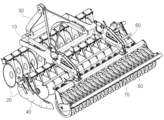
도 1은 본 발명에 따른 무동력 디스크 해로우가 도시된 사시도이다.
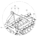
도 2는 본 발명에 따른 무동력 디스크 해로우의 배면사시도이다.
도 3은 본 발명에 따른 무동력 디스크 해로우의 마스트 그룹을 나타낸 확대도이다.
도 4는 본 발명에 따른 무동력 디스크 해로우의 메인프레임 및 마스트 그룹이 도시된 사시도이다.
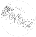
도 5는 본 발명에 따른 무동력 디스크 해로우에서 디스크 갱의 단부가 도시된 사시도이다.
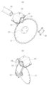
도 6은 본 발명에 따른 무동력 디스크 해로우에 구비된 디플렉터 조립체의 분해도이다.
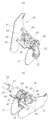
도 7은 본 발명에 따른 무동력 디스크 해로우에서 디플렉터 조립체의 전개 전후의 모습을 나타낸 참고도이다.
도 8은 본 발명에 따른 무동력 디스크 해로우의 롤러 암 및 깊이 조절 실린더가 도시된 사시도이다.
도 9는 본 발명에 따른 무동력 디스크 해로우의 진압부에 결합되는 스크래퍼 조립체의 분해 사시도이다.
Figure 1 is a perspective view showing a non-powered disk harrow according to the present invention.
Figure 2 is a rear perspective view of a non-powered disc harrow according to the present invention.
Figure 3 is an enlarged view showing the mast group of a non-powered disk harrow according to the present invention.
Figure 4 is a perspective view showing the main frame and mast group of a non-powered disk harrow according to the present invention.
Figure 5 is a perspective view showing the end of the disk gang in the non-powered disk harrow according to the present invention.
Figure 6 is an exploded view of the deflector assembly provided in the non-powered disk harrow according to the present invention.
Figure 7 is a reference diagram showing the deflector assembly before and after deployment in the non-powered disk harrow according to the present invention.
Figure 8 is a perspective view showing the roller arm and depth adjustment cylinder of the non-powered disk harrow according to the present invention.
Figure 9 is an exploded perspective view of the scraper assembly coupled to the suppressing portion of the non-powered disk harrow according to the present invention.
이하, 본 발명의 바람직한 실시예를 첨부된 도면을 참조하여 상세히 설명하기로 한다.Hereinafter, preferred embodiments of the present invention will be described in detail with reference to the attached drawings.
본 발명에서 사용되는 용어들은 본 발명에서의 기능을 고려하여 정의된 용어들로서, 이는 사용자, 운용자의 의도 또는 관례에 따라 달라질 수 있으므로, 이러한 용어들에 대한 정의는 본 고안의 기술적 사항에 부합되는 의미와 개념으로 해석되어야 할 것이다.The terms used in the present invention are terms defined in consideration of the functions in the present invention, and may vary depending on the intention or custom of the user or operator, so the definitions of these terms are defined in accordance with the technical details of the present invention. It should be interpreted as a concept.
첨부도면의 도 1 내지 도 9는 본 발명에 따른 무동력 디스크 해로우를 설명하기 위하여 나타낸 도면들이다.Figures 1 to 9 of the attached drawings are diagrams showing a non-powered disk harrow according to the present invention.
본 발명에 따른 무동력 디스크 해로우는 도 1 내지 도 9에 도시된 바와 같이, 메인프레임(10)과, 한 쌍의 디스크 갱(20), 마스트 그룹(30), 메인프레임(10) 양측의 디플렉터 조립체(40), 메인프레임(10) 후방의 진압부(50), 리어 타인(60), 스크래퍼 조립체(70)를 포함하여 이루어진다. As shown in FIGS. 1 to 9, the non-powered disk harrow according to the present invention includes a
이때, 진압부(50)는 작업 깊이 조정을 위하여 메인프레임(10)의 후방에 회동 가능하게 연결된 롤러 고정암(55)에 고정되고, 롤러 고정암(55)은 깊이 조절 실린더(56)에 의해 상하 방향으로 회동하도록 구성된다.At this time, the
메인프레임(10)은 다른 구성요소들이 장치되는 부분으로, 다른 구성요소들을 고정 및 지지하게 된다. The
메인프레임(10)은 도 4에 도시된 바와 같이, 폭방향으로 배치되어 디스크 갱(20)이 연결되는 전방프레임(11) 및 후방프레임(12)과, 전후 방향으로 설치되어 전방프레임(11)과 후방프레임(12)을 연결하는 한 쌍의 연결프레임(13)과, 전방프레임(11)과 후방프레임(12)의 양측 단부를 연결하는 한 쌍의 사이드 프레임(14)과, 전방프레임(11)과 후방프레임(12)을 대각선으로 연결하는 보강프레임(15)을 포함하여 이루어진다.As shown in FIG. 4, the
이때, 전방프레임(11)에는 트랙터의 3점링크 중 하부링크가 연결되는 링크연결부(16)가 용접됨과 아울러 전방프레임(11)과 후방프레임(12)의 하부측에 디스크 갱(20)의 연결을 위한 연결브래킷(17)이 각각 용접된다. At this time, the link connection part 16 to which the lower link of the three-point links of the tractor is connected is welded to the front frame 11, and the
그리고 사이드프레임(14)의 후방측에는 진압부(50)의 연결을 위한 롤러 고정암(55) 및 깊이 조절 실린더(56)가 연결되는 롤러연결부(14')가 형성되는 것이 바람직하다.In addition, it is preferable that a roller connection portion 14' to which the
디스크 갱(20)은 지면에 접촉되어 경운작업을 실시할 수 있도록 복수의 디스크(21)가 일정 간격으로 배치되어 이루어지는 것으로, 한 쌍의 디스크 갱(20)이 전후 방향으로 일정 정도 이격되게 배치된다. The
구체적으로, 디스크 갱(20)은 도 1과 도 2 및 도 5에 도시된 바와 같이, 외주면에 요철이 형성된 복수의 디스크(21)와, 복열 베어링으로 이루어지며 디스크(21)의 중심에 설치되어 디스크(21)가 자유회전하도록 하는 허브(22)와, 디스크(21)를 지지하도록 각 디스크(21)의 허브(22)가 연결되는 복수의 디스크 암(23)과, 사각의 삽입공간(25)을 형성하도록 디스크 암(23)의 상부에 접합되는 캡(24)과, 디스크 암(23)과 캡(24) 사이의 삽입공간(25)에 삽입되어 복수의 디스크 암(23)을 일체로 연결하며 고정브래킷(27)을 통해 메인프레임(10)의 연결브래킷(17)에 연결되는 사각의 연결파이프(26) 및 최외각 디스크 암(23)에 설치되어 연결파이프(26)의 양단을 지지하는 한 쌍의 루버텐션(28)을 포함하여 이루어진다.Specifically, as shown in FIGS. 1, 2, and 5, the
이때, 디스크(21)는 지면 기준으로 대략 17도 정도 측면을 바라보도록 틀어지게 배치되는 것이 바람직하다. At this time, it is preferable that the
그리고 삽입공간(25)의 내측면에는 각각 연결파이프(26)의 각면을 탄성 지지하는 고무봉(29)이 설치됨으로써, 디스크 갱(20)의 연결파이프(26)와 캡(24) 및 디스크 암(23)이 부하에 견딜 수 있도록 하는 것이 바람직하다. In addition, a
이에 따라, 디스크(21)가 요철 등의 장애물을 안전하게 넘어갈 수 있게 된다.Accordingly, the
마스트 그룹(30)은 메인프레임(10)을 트랙터 등의 견인장치에 연결할 수 있도록 메인프레임(10)에 설치되는 것이다. The
구체적으로, 마스트 그룹(30)은 도 3과 도 4에 도시된 바와 같이, 메인프레임(10)의 전방프레임(11)에 일정 간격을 두고 설치된 전방브래킷(32)에 경사지게 설치되어 상부측이 서로 연결되며 트랙터의 3점링크 중 상부링크가 연결되는 한 쌍의 전방 마스트(31)와, 메인프레임(10)의 후방프레임(12)에 일정 간격으로 설치된 후방브래킷(34)에 연결되며 상단부가 전방 마스트(31)의 상부 뒤쪽에 연결되는 한 쌍의 후방 마스트(33)와, 후방 마스트(33)의 상부측을 서로 연결하는 보강부재(35)를 포함하여 이루어진다.Specifically, as shown in FIGS. 3 and 4, the
따라서, 마스트 그룹을 이용하여 트랙터 등의 견인장치에 연결함으로써 동력을 사용하지 않고도 경운 작업을 수행할 수 있게 된다.Therefore, by connecting to a traction device such as a tractor using a mast group, it is possible to perform tillage work without using power.
디플렉터 조립체(40)는 메인프레임(10)의 양측에 전개 가능하게 설치되어 경운 과정에서 흙이 밖으로 유실되지 않도록 하는 것이다. The
구체적으로, 디플렉터 조립체(40)는 도 6과 도 7에 도시된 바와 같이, 디스크 갱(20)의 외측에서 흙의 이탈을 방지하며 선단부가 내측을 향해 일정 정도 경사지게 절곡된 차단판(41)과, 최외각 디스크 암(23)에 설치되어 디플렉터 조립체(40)가 끼움 결합되는 디플렉터 고정부(48)와, 사각파이프로 이루어지며 일측 단부에 디플렉터 고정부(48)에 끼움 결합되는 결합판(43)이 구비된 지지부(42)와, 사각파이프로 이루어지며 외측 단부에 차단판(41)이 고정되는 고정판(44)이 일체로 결합되고 지지부(42)의 외측에 삽입 결합되는 차단판 고정부(45)와, 차단판(41)과 차단판 고정부(45)의 고정판(44)을 연결하는 한 쌍의 연결부재(46)를 포함하여 이루어진다.Specifically, as shown in FIGS. 6 and 7, the
이때, 디플렉터 조립체(40)는 차단판(41)의 위치를 조정하고 차단판(41)을 접거나 전개할 수 있도록 지지부(42)에 상하 방향의 관통공(42')이 일정 간격으로 복수개 형성됨과 아울러 차단판 고정부(45)에 상하 방향의 관통공(45')이 형성된다. At this time, the
따라서, 작업을 하지 않을 때에는 도 7의 (a)와 같이 차단판(41)을 접어두고, 작업을 수행할 때에만 도 7의 (b)와 같이 차단판(41)을 전개할 수 있게 된다. Therefore, when not working, the blocking
그리고, 차단판(41)의 각도를 조절할 수 있도록 한 쌍의 연결부재(46) 중 전방측 연결부재에 복수개의 관통공(46')이 형성되는 것이 바람직하다.In addition, it is preferable that a plurality of through holes 46' are formed in the front connecting member of the pair of connecting
진압부(50)는일정 간격으로 배치된 복수의 진압롤러(51)를 이영하여 지면을 진압하고 파종을 위한 평탄화 작업을 수행하는 것이다. The
구체적으로, 진압부(50)는 도 9에 도시된 바와 같이, 외주면에 요철이 형성된 복수개의 진압롤러(51)와, 메인프레임(10)에 롤러 고정암(55)으로 연결된 진압부프레임(52)과, 진압롤러(51)를 연결하며 양단에 허브축(54')이 구비된 커버(54)가 결합된 회전축(53)과, 진압롤러(51)의 최외측에서 회전축에 결합되는 커버롤러(57)와, 일측 단부는 진압부프레임(52)에 용접되고 타측 단부에 커버(54)의 허브축(54')이 삽입되는 허브축 삽입공(58')이 형성된 회전축 지지대(58)를 포함하여 이루어진다.Specifically, as shown in FIG. 9, the
그리고 진압부(50)를 메인프레임(10)에 연결하는 롤러 고정암(55)은 도 8에 도시된 바와 같이, 일측 단부가 사이드 프레임(14)의 롤러연결부(14') 끝단에 회동 가능하게 연결되고 타측 단부는 진압부프레임(51)에 연결되는 한 쌍의 하부암(55a)과, 상부측으로 돌출되도록 하부암(55a)에 설치되며 상측 끝단에 사이드 프레임(14)의 롤러 연결부(14') 상단에 설치된 깊이 조절 실린더(56)의 로드가 연결되는 한 쌍의 상부암(55b)을 포함하여 이루어진다.And, as shown in FIG. 8, the
리어 타인(60)은 디스크(21)가 경운한 토지를 고르게 만들고 파종을 위한 평탄화작업을 수행하는 것으로, 도 9에 도시된 바와 같이 프레임에 상단이 연결되고 하단은 자유롭게 움직이는 한 쌍의 와이어로 이루어지며, 진압부(50)의 전방에 설치된다. The
스크래퍼 조립체(70)는 진압부(50)의 롤러에 붙어있는 흙을 털어주는 다수의 스크래퍼(71) 및 경운 후 해당 부분의 골을 메워주는 다수의 스키드(72)로 이루어지는 것이다. The
이러한 스크래퍼 조립체(70)는 도 9에 도시된 바와 같이, 진압롤러(51) 사이에 배치되어 진압롤러(51)에 붙어 있는 흙을 털어주는 스크래퍼(71)와, 회전축(53)을 감싸는 구조로 형성되고 탄성을 이용하여 경운 과정에서 발생한 골을 메워주는 스키드(72)와, 스크래퍼(71)와 스키드(72)가 고정되는 복수의 스크래퍼 고정판(73)과, 회전축(53)으로부터 이격되게 배치되며 복수의 스크래퍼 고정판(73)이 설치되는 스크래퍼프레임(75)과, 일측 단부는 스크래퍼프레임(75)에 연결되고 타측 단부는 회전축 지지대(58)에 연결됨과 아울러 허브축 삽입공(74')이 형성되어 스크래퍼프레임(75)을 지지하는 스크래퍼 지지대(74)를 포함하여 이루어진다.As shown in FIG. 9, this
이때, 스크래퍼 조립체(70)는 진압부프레임(52)에 대한 스크래퍼프레임(75)의 상대 위치를 조절할 수 있도록 구성되는 것이 바람직하다. At this time, the
이를 위하여, 스크래퍼프레임(75)에 구비된 연결브래킷(76)에 일정 간격으로 복수의 관통공(76')이 형성되고 스크래퍼 지지대(74)의 타측 단부에도 일정 간격으로 복수의 관통공(74a)이 형성된다. For this purpose, a plurality of through holes 76' are formed at regular intervals in the
그리고 회전축 지지대(58)의 허브축 삽입공(58')과 스크래퍼 지지대(74)의 허브축 삽입공(74') 주위에 원주 방향을 따라 일정 간격으로 연결공(58")(74")이 각각 관통 형성됨으로써 조절된 각도를 고정할 수 있도록 하는 것이 바람직하다. And connection holes (58") (74") are formed at regular intervals along the circumferential direction around the hub axis insertion hole (58') of the rotation axis support (58) and the hub axis insertion hole (74') of the scraper support (74). It is preferable that the adjusted angle can be fixed by being formed through each.
이에 따라, 상술한 구성으로 이루어지는 본 발명에 따른 무동력 디스크 해로우를 이용하여 경운 작업을 수행하는 것에 대하여 다음과 같이 설명한다.Accordingly, performing tillage work using the non-powered disk harrow according to the present invention having the above-described configuration will be described as follows.
마스트 그룹(30)을 이용하여 트랙터 등의 견인장치에 메인프레임(10)을 연결하고, 작업속도 약 8~20㎞로 이동하면서 작업을 수행한다. The main frame (10) is connected to a traction device such as a tractor using the mast group (30), and the work is performed while moving at a work speed of about 8 to 20 km.
이때, 장치의 무게가 대략 1700㎏으로 무겁기 때문에 디스크 갱(20)의 디스크(21)가 땅을 파고 든 상태로 회전하게 되며, 디스크(20)의 각도로 인해 작물의 뿌리가 잘리면서 경운된다. 이때, 디플렉터 조립체(40)가 경운 과정에서 흙이 외부로 배출되지 않도록 차단하게 된다.At this time, since the weight of the device is approximately 1700 kg, the
디스크 갱(20)에 의한 이중 경운작업이 이루어지면, 리어 테인(60)이 경운된 따을 고르게 만들어주고 평탄화시키게 된다. When a double tilling operation is performed by the
그리고 진압부(50)의 진압롤러(51)가 회전하면서 들뜬 흙을 진압하여 파종을 위한 평탄화 작업을 수행한다. Then, the
이 과정에서 스크래퍼 조립체(70)의 스크래퍼(71)가 진압롤러(51)의 흙을 긁어 털어줌으로써 습한 곳을 작업할 때 짚 등의 이물질이 흙과 같이 구르는 과정에서 덩치가 커지는 현상을 막아주게 된다, In this process, the
그리고 스크래퍼 조립체(70)의 스키드(72)는 경운 후 해당 부분의 골을 메워주거나 파종시 종자가 노출되지 않도록 흙을 덮어주게 된다.In addition, the
이상에서 설명한 실시예는 본 발명의 바람직한 실시예를 설명한 것에 불과하고 이러한 실시예에 극히 한정되는 것은 아니며, 본 발명의 기술적 사상과 청구범위 내에서 이 기술분야의 당해업자에 의하여 다양한 수정과 변형 등이 이루어질 수 있다 할 것이며, 이는 본 발명의 기술적 범위에 속한다 할 것이다.The embodiments described above merely describe preferred embodiments of the present invention and are not extremely limited to these embodiments, and various modifications and variations may be made by those skilled in the art within the technical spirit and scope of the claims of the present invention. It will be said that this can be achieved, and it will be said that it falls within the technical scope of the present invention.
10 : 메인프레임
11 : 전방프레임
12 : 후방프레임
13 : 연결프레임
14 : 사이드 프레임
14' : 롤러연결부
15 : 보강프레임
16 : 링크연결부
17 : 연결브래킷
20 : 디스크 갱
21 : 디스크
22 : 허브
23 : 디스크 암
24 : 커버
25 : 수용공간
26 : 연결파이프
27 : 고정브래킷
28 : 루버텐션
29 : 고무봉
30 : 마스트 그룹
31 : 전방 마스트
32 : 전방브래킷
33 : 후방 마스트
34 : 후방브래킷
35 : 보강부재
40 : 디플렉터 조립체
41 : 차단판
42 : 지지부
43 : 결합판
44 : 고정판
45 : 차단판 고정부
46 :연결부재
50 : 진압부
51 : 진압롤러
52 : 진압부프레임
53 : 회전축
54 : 커버
54' : 허브축
55 : 롤러 고정암
56 : 높이 조절 실린더
57 : 커버롤러
58 : 회전축 지지대
60 : 리어 테인
70 : 스크래퍼 조립체
71 : 스크래퍼
72 : 스키드
73 : 스크래퍼 고정판
74 : 스크래퍼 지지대
75 : 스크래퍼프레임
76 : 연결브래킷10: main frame 11: front frame
12: rear frame 13: connection frame
14: Side frame 14': Roller connection
15: Reinforcement frame 16: Link connection part
17: Connection bracket 20: Disk gang
21: Disk 22: Hub
23: Disk arm 24: Cover
25: Accommodation space 26: Connection pipe
27: fixing bracket 28: louver tension
29: Rubber rod 30: Mast group
31: front mast 32: front bracket
33: rear mast 34: rear bracket
35: Reinforcing member 40: Deflector assembly
41: blocking plate 42: support part
43: coupling plate 44: fixing plate
45: blocking plate fixing part 46: connecting member
50: Suppression unit 51: Suppression roller
52: suppression frame 53: rotation axis
54: Cover 54': Hub axis
55: Roller fixing arm 56: Height adjustment cylinder
57: cover roller 58: rotation axis support
60: rear tin 70: scraper assembly
71: scraper 72: skid
73: scraper fixing plate 74: scraper support
75: scraper frame 76: connection bracket
Claims (11)
지면에 접촉되어 경운작업을 실시할 수 있도록 복수의 디스크가 일정 간격으로 배치되어 이루어지며 전후 방향으로 일정 정도 이격되게 배치되는 한 쌍의 디스크 갱;
메인프레임을 견인장치에 연결할 수 있도록 메인프레임에 설치되는 마스트 그룹;
메인프레임의 양측에 전개 가능하게 설치되어 경운 과정에서 흙이 밖으로 유실되지 않도록 하는 디플렉터 조립체;
일정 간격으로 배치된 복수의 진압롤러를 포함하며 지면을 진압하고 파종을 위한 평탄화 작업을 수행하는 진압부;
디스크가 경운한 토지를 고르게 만들고 파종을 위한 평탄화작업을 수행하도록 진압부의 전방에 설치되는 리어 타인; 및
진압부의 롤러에 붙어있는 흙을 털어주는 다수의 스크래퍼 및 경운 후 해당 부분의 골을 메워주는 다수의 스키드로 이루어진 스크래퍼 조립체;를 포함하는 것을 특징으로 하는 무동력 디스크 해로우.mainframe;
A pair of disk gangs consisting of a plurality of disks arranged at regular intervals so as to be in contact with the ground and perform a tillage operation, and spaced a certain amount apart in the front and rear directions;
A mast group installed on the mainframe to connect the mainframe to a towing device;
A deflector assembly that is deployably installed on both sides of the main frame to prevent soil from being lost during the tillage process;
A suppression unit that includes a plurality of suppression rollers arranged at regular intervals and suppresses the ground and performs a leveling operation for seeding;
A rear tine installed in front of the suppression unit so that the disc evens out the tilled land and performs leveling work for sowing; and
A non-powered disc harrow comprising a scraper assembly consisting of a plurality of scrapers that shake off the dirt attached to the roller of the suppression unit and a plurality of skids that fill in the grooves of the corresponding area after tilling.
진압부는 작업 깊이 조정을 위하여 메인프레임의 후방에 회동 가능하게 연결된 롤러 고정암에 고정되고, 롤러 고정암은 깊이 조절 실린더에 의해 상하 방향으로 회동할 수 있도록 한 것을 특징으로 하는 무동력 디스크 해로우.In claim 1,
A non-powered disc harrow characterized in that the suppression unit is fixed to a roller fixing arm rotatably connected to the rear of the main frame to adjust the working depth, and the roller fixing arm can be rotated in the up and down directions by a depth adjustment cylinder.
메인프레임은 폭방향으로 배치되어 디스크 갱이 연결되는 전방프레임 및 후방프레임과, 전후 방향으로 설치되어 전방프레임과 후방프레임을 연결하는 한 쌍의 연결프레임과, 전방프레임과 후방프레임의 양측 단부를 연결하는 한 쌍의 사이드 프레임과, 전방프레임과 후방프레임을 대각선으로 연결하는 보강프레임을 포함하고,
전방프레임에 트랙터의 3점링크 중 하부링크가 연결되는 링크연결부가 용접됨과 아울러 전방프레임과 후방프레임의 하부측에 디스크 갱의 연결을 위한 연결브래킷이 각각 용접되며, 사이드프레임의 후방측에 롤러 고정암 및 깊이 조절 실린더가 연결되는 롤러연결부가 형성된 것을 특징으로 하는 무동력 디스크 해로우.In claim 1,
The main frame consists of a front frame and a rear frame arranged in the width direction and connected to the disk gang, a pair of connecting frames installed in the front and rear directions to connect the front frame and the rear frame, and a pair of connecting frames connecting both ends of the front frame and the rear frame. It includes a pair of side frames and a reinforcement frame diagonally connecting the front frame and the rear frame,
The link connection part where the lower link of the tractor's three-point link is connected is welded to the front frame, and a connecting bracket for connecting the disk gang is welded to the lower part of the front frame and rear frame, respectively, and a roller is fixed to the rear side of the side frame. A non-powered disc harrow characterized by a roller connection where the arm and depth adjustment cylinder are connected.
롤러 고정암은 일측 단부가 사이드 프레임의 롤러연결부 끝단에 회동 가능하게 연결되고 타측 단부는 진압부프레임에 연결되는 한 쌍의 하부암과, 상부측으로 돌출되도록 하부암에 설치되며 상측 끝단에 사이드 프레임의 롤러 연결부 상단에 설치된 깊이 조절 실린더의 로드가 연결되는 한 쌍의 상부암을 포함하는 것을 특징으로 하는 무동력 디스크 해로우.In claim 3,
The roller fixing arm has a pair of lower arms, one end of which is rotatably connected to the end of the roller connection of the side frame, and the other end of which is connected to the suppressor frame, and is installed on the lower arm to protrude toward the upper side, and has a side frame at the upper end. A non-powered disc harrow comprising a pair of upper arms to which the rod of the depth adjustment cylinder installed at the top of the roller connection is connected.
디스크 갱은 외주면에 요철이 형성된 복수의 디스크와, 복열 베어링으로 이루어지며 디스크의 중심에 설치되어 디스크가 자유회전하도록 하는 허브와, 디스크를 지지하도록 각 디스크의 허브가 연결되는 복수의 디스크 암과, 사각의 삽입공간을 형성하도록 디스크 암의 상부에 접합되는 캡과, 디스크 암과 캡 사이의 삽입공간에 삽입되어 복수의 디스크 암을 일체로 연결하며 고정브래킷을 통해 메인프레임의 연결브래킷에 연결되는 사각의 연결파이프 및 최외각 디스크 암에 설치되어 연결파이프의 양단을 지지하는 한 쌍의 루버텐션을 포함하는 것을 특징으로 하는 무동력 디스크 해로우.In claim 1,
The disk gang consists of a plurality of disks with irregularities formed on the outer peripheral surface, a double-row bearing, a hub installed at the center of the disk to allow the disk to freely rotate, and a plurality of disk arms to which the hubs of each disk are connected to support the disk, A cap that is joined to the top of the disk arm to form a square insertion space, and a square cap that is inserted into the insertion space between the disk arm and the cap to connect multiple disk arms as one unit and is connected to the connection bracket of the main frame through a fixing bracket. A non-powered disc harrow comprising a pair of louver tensions installed on the connection pipe and the outermost disk arm to support both ends of the connection pipe.
마스트 그룹은 메인프레임의 전방프레임에 일정 간격을 두고 설치된 전방브래킷에 경사지게 설치되어 상부측이 서로 연결되며 트랙터의 3점링크 중 상부링크가 연결되는 한 쌍의 전방 마스트와, 메인프레임의 후방프레임에 일정 간격으로 설치된 후방브래킷에 연결되며 상단부가 전방 마스트의 상부 뒤쪽에 연결되는 한 쌍의 후방 마스트와, 후방 마스트의 상부측을 서로 연결하는 보강부재를 포함하는 것을 특징으로 하는 무동력 디스크 해로우.In claim 1,
The mast group is installed at an angle on the front bracket installed at regular intervals on the front frame of the main frame, and the upper parts are connected to each other. A pair of front masts to which the upper link of the three-point link of the tractor is connected, and the rear frame of the main frame A non-powered disc harrow comprising a pair of rear masts connected to rear brackets installed at regular intervals and the upper end connected to the upper rear of the front mast, and a reinforcing member connecting the upper sides of the rear mast to each other.
디플렉터 조립체는 디스크 갱의 외측에서 흙의 이탈을 방지하며 선단부가 내측을 향해 일정 정도 경사지게 절곡된 차단판과, 최외각 디스크 암에 설치되어 디플렉터 조립체가 끼움 결합되는 디플렉터 고정부와, 사각파이프로 이루어지며 일측 단부에 디플렉터 고정부에 끼움 결합되는 결합판이 구비된 지지부와, 사각파이프로 이루어지며 외측 단부에 차단판이 고정되는 고정판이 일체로 결합되고 지지부의 외측에 삽입 결합되는 차단판 고정부와, 차단판과 차단판 고정부의 고정판을 연결하는 한 쌍의 연결부재를 포함하는 것을 특징으로 하는 무동력 디스크 해로우.In claim 1,
The deflector assembly consists of a blocking plate whose tip is bent at a certain incline to prevent soil from leaving the outside of the disk gang, a deflector fixture installed on the outermost disk arm into which the deflector assembly is inserted, and a square pipe. A support part with a coupling plate fitted to the deflector fixing part at one end, a fixing plate made of a square pipe and fixed to the outer end of the blocking plate, and a blocking plate fixing part inserted and coupled to the outside of the support part, and a blocking plate. A non-powered disc harrow comprising a pair of connecting members connecting the plate and the fixing plate of the blocking plate fixture.
디플렉터 조립체는 차단판의 위치를 조정하고 차단판을 접거나 전개할 수 있도록 함과 아울러 차단판의 각도를 조절할 수 있도록 구성되는 것을 특징으로 하는 무동력 디스크 해로우.In claim 7,
A non-powered disc harrow characterized in that the deflector assembly is configured to adjust the position of the blocking plate, fold or unfold the blocking plate, and adjust the angle of the blocking plate.
진압부는 외주면에 요철이 형성된 복수개의 진압롤러와, 메인프레임에 롤러 고정암으로 연결된 진압부프레임과, 진압롤러를 연결하며 양단에 허브축이 구비된 커버가 결합된 회전축과, 진압롤러의 최외측에서 회전축에 결합되는 커버롤러와, 일측 단부는 진압부프레임에 용접되고 타측 단부에 커버의 허브축이 삽입되는 허브축 삽입공이 형성된 회전축 지지대를 포함하는 것을 특징으로 하는 무동력 디스크 해로우.In claim 1,
The suppression unit includes a plurality of suppression rollers with irregularities formed on the outer peripheral surface, a suppression unit frame connected to the main frame with a roller fixing arm, a rotating shaft connected to the suppression rollers and a cover equipped with hub axes on both ends, and the outermost side of the suppression roller. A non-powered disk harrow comprising a cover roller coupled to a rotating shaft, and a rotating shaft support having one end welded to the suppression frame and a hub shaft insertion hole formed at the other end into which the hub shaft of the cover is inserted.
스크래퍼 조립체는 진압롤러 사이에 배치되어 진압롤러에 붙어 있는 흙을 털어주는 스크래퍼와, 회전축을 감싸는 구조로 형성되고 탄성을 이용하여 경운 과정에서 발생한 골을 메워주는 스키드와, 스크래퍼와 스키드가 고정되는 복수의 스크래퍼 고정판과, 회전축으로부터 이격되게 배치되며 복수의 스크래퍼 고정판이 설치되는 스크래퍼프레임과, 일측 단부는 스크래퍼프레임에 연결되고 타측 단부는 회전축 지지대에 연결됨과 아울러 허브축 삽입공이 형성되어 스크래퍼프레임을 지지하는 스크래퍼 지지대를 포함하는 것을 특징으로 하는 무동력 디스크 해로우.In claim 9,
The scraper assembly includes a scraper that is placed between the suppression rollers to shake off the dirt stuck to the suppression rollers, a skid that is formed in a structure that surrounds the rotating shaft and uses elasticity to fill in the grooves created during the tillage process, and a plurality of parts to which the scraper and the skid are fixed. A scraper fixing plate, a scraper frame arranged to be spaced apart from the rotating shaft and equipped with a plurality of scraper fixing plates, one end connected to the scraper frame and the other end connected to the rotating shaft support, and a hub shaft insertion hole is formed to support the scraper frame. A non-powered disc harrow comprising a scraper support.
스크래퍼 지지대는 진압부프레임에 대한 스크래퍼프레임의 상대 위치를 조절할 수 있도록 구성된 것을 특징으로 하는 무동력 디스크 해로우.In claim 10,
A non-powered disc harrow characterized in that the scraper support is configured to adjust the relative position of the scraper frame with respect to the suppressor frame.
Priority Applications (1)
| Application Number | Priority Date | Filing Date | Title |
|---|---|---|---|
| KR1020220124376A KR20240044867A (en) | 2022-09-29 | 2022-09-29 | Non-motorized disc harrow |
Applications Claiming Priority (1)
| Application Number | Priority Date | Filing Date | Title |
|---|---|---|---|
| KR1020220124376A KR20240044867A (en) | 2022-09-29 | 2022-09-29 | Non-motorized disc harrow |
Publications (1)
| Publication Number | Publication Date |
|---|---|
| KR20240044867A true KR20240044867A (en) | 2024-04-05 |
Family
ID=90714136
Family Applications (1)
| Application Number | Title | Priority Date | Filing Date |
|---|---|---|---|
| KR1020220124376A KR20240044867A (en) | 2022-09-29 | 2022-09-29 | Non-motorized disc harrow |
Country Status (1)
| Country | Link |
|---|---|
| KR (1) | KR20240044867A (en) |
Citations (4)
| Publication number | Priority date | Publication date | Assignee | Title |
|---|---|---|---|---|
| KR20090120182A (en) | 2008-05-19 | 2009-11-24 | 김준환 | Cultivator with harrow and rotorbator |
| KR20140131204A (en) | 2013-05-03 | 2014-11-12 | 제트스타 주식회사 | Ridging plow for tractor |
| KR101740377B1 (en) | 2016-09-27 | 2017-05-26 | 주식회사 그린맥스 | Disc Harrow Topdressers type of chisel |
| KR101971129B1 (en) | 2017-10-31 | 2019-04-22 | 주식회사 그린맥스 | Non-motorized disc harrows with improved driving stability |
-
2022
- 2022-09-29 KR KR1020220124376A patent/KR20240044867A/en not_active Application Discontinuation
Patent Citations (4)
| Publication number | Priority date | Publication date | Assignee | Title |
|---|---|---|---|---|
| KR20090120182A (en) | 2008-05-19 | 2009-11-24 | 김준환 | Cultivator with harrow and rotorbator |
| KR20140131204A (en) | 2013-05-03 | 2014-11-12 | 제트스타 주식회사 | Ridging plow for tractor |
| KR101740377B1 (en) | 2016-09-27 | 2017-05-26 | 주식회사 그린맥스 | Disc Harrow Topdressers type of chisel |
| KR101971129B1 (en) | 2017-10-31 | 2019-04-22 | 주식회사 그린맥스 | Non-motorized disc harrows with improved driving stability |
Similar Documents
| Publication | Publication Date | Title |
|---|---|---|
| AU759731B2 (en) | Mid row banding coulter drill | |
| US4187916A (en) | Soil conditioning and seed bed preparing apparatus | |
| US3983943A (en) | Soil cultivating implement combinations | |
| EP2436250A1 (en) | Soil working apparatus and method | |
| CN200987258Y (en) | Vibrating deep loosener | |
| US7322302B1 (en) | Seedling planter | |
| KR101023322B1 (en) | Tractor Attached Cover Stopper | |
| CN111642150B (en) | Incomplete membrane cleaning and recycling machine draw gear | |
| CA2066214C (en) | Direct drill stump jump seeder | |
| KR20240044867A (en) | Non-motorized disc harrow | |
| KR100991512B1 (en) | Transplanter device for farming machine | |
| CN112243622A (en) | Integrated machine for plowing, deeply fertilizing beet strips | |
| JP2001112303A (en) | Tillage working machine | |
| CA2776762C (en) | Ditch forming implement | |
| EP2160936B1 (en) | Agricultural implement | |
| WO2021044402A1 (en) | A device | |
| CN222053787U (en) | Ploughing and leveling integrated machine | |
| KR20160114300A (en) | Plough equipment having crush edge | |
| KR200368669Y1 (en) | Multipurpose weeder | |
| CN222235467U (en) | Rotary tillage and sowing machine | |
| CN218603935U (en) | Ditching device is planted to flax | |
| CN220255021U (en) | Rotary tillage depth adjusting device | |
| CN220629982U (en) | Soil preparation machine with interval adjustment function | |
| CN222073814U (en) | A deep tillage and stone picking machine for cultivated land | |
| CA2854653C (en) | Universal custom agricultural field preparation implement |
Legal Events
| Date | Code | Title | Description |
|---|---|---|---|
| PA0109 | Patent application | ||
| PG1501 | Laying open of application | ||
| E902 | Notification of reason for refusal | ||
| PE0902 | Notice of grounds for rejection |
Comment text: Notification of reason for refusal Patent event date: 20250102 Patent event code: PE09021S01D |