KR20240026068A - Multi-state pulsing for high aspect ratio etch - Google Patents
Multi-state pulsing for high aspect ratio etch Download PDFInfo
- Publication number
- KR20240026068A KR20240026068A KR1020227045635A KR20227045635A KR20240026068A KR 20240026068 A KR20240026068 A KR 20240026068A KR 1020227045635 A KR1020227045635 A KR 1020227045635A KR 20227045635 A KR20227045635 A KR 20227045635A KR 20240026068 A KR20240026068 A KR 20240026068A
- Authority
- KR
- South Korea
- Prior art keywords
- power level
- state
- source
- bias
- pulsed
- Prior art date
Links
- 238000000034 method Methods 0.000 claims abstract description 65
- 238000012545 processing Methods 0.000 claims abstract description 60
- 230000008569 process Effects 0.000 claims abstract description 52
- 238000005530 etching Methods 0.000 claims abstract description 25
- 239000000758 substrate Substances 0.000 claims abstract description 24
- 238000002161 passivation Methods 0.000 claims description 7
- 230000000694 effects Effects 0.000 claims description 2
- 235000012431 wafers Nutrition 0.000 description 43
- 239000007789 gas Substances 0.000 description 25
- 238000004519 manufacturing process Methods 0.000 description 22
- 239000004065 semiconductor Substances 0.000 description 18
- 239000000463 material Substances 0.000 description 11
- 238000000151 deposition Methods 0.000 description 9
- 230000008021 deposition Effects 0.000 description 9
- 239000003990 capacitor Substances 0.000 description 8
- 230000006872 improvement Effects 0.000 description 8
- 238000004891 communication Methods 0.000 description 7
- 229910052581 Si3N4 Inorganic materials 0.000 description 6
- 239000012530 fluid Substances 0.000 description 6
- 150000002500 ions Chemical class 0.000 description 6
- 230000007935 neutral effect Effects 0.000 description 6
- HQVNEWCFYHHQES-UHFFFAOYSA-N silicon nitride Chemical compound N12[Si]34N5[Si]62N3[Si]51N64 HQVNEWCFYHHQES-UHFFFAOYSA-N 0.000 description 6
- XUIMIQQOPSSXEZ-UHFFFAOYSA-N Silicon Chemical compound [Si] XUIMIQQOPSSXEZ-UHFFFAOYSA-N 0.000 description 4
- 238000004590 computer program Methods 0.000 description 4
- 239000000112 cooling gas Substances 0.000 description 4
- 238000005516 engineering process Methods 0.000 description 4
- 239000002184 metal Substances 0.000 description 4
- 229910052751 metal Inorganic materials 0.000 description 4
- 239000000203 mixture Substances 0.000 description 4
- 229910052710 silicon Inorganic materials 0.000 description 4
- 239000010703 silicon Substances 0.000 description 4
- 238000003860 storage Methods 0.000 description 4
- VYPSYNLAJGMNEJ-UHFFFAOYSA-N Silicium dioxide Chemical compound O=[Si]=O VYPSYNLAJGMNEJ-UHFFFAOYSA-N 0.000 description 3
- 229910052799 carbon Inorganic materials 0.000 description 3
- 230000006870 function Effects 0.000 description 3
- 238000004886 process control Methods 0.000 description 3
- 238000012546 transfer Methods 0.000 description 3
- 238000000231 atomic layer deposition Methods 0.000 description 2
- 239000000919 ceramic Substances 0.000 description 2
- 238000005229 chemical vapour deposition Methods 0.000 description 2
- 239000000470 constituent Substances 0.000 description 2
- 230000001276 controlling effect Effects 0.000 description 2
- 238000013500 data storage Methods 0.000 description 2
- 238000010586 diagram Methods 0.000 description 2
- 238000010438 heat treatment Methods 0.000 description 2
- 238000007726 management method Methods 0.000 description 2
- 230000003287 optical effect Effects 0.000 description 2
- 238000005240 physical vapour deposition Methods 0.000 description 2
- 238000001020 plasma etching Methods 0.000 description 2
- 239000000376 reactant Substances 0.000 description 2
- OKTJSMMVPCPJKN-UHFFFAOYSA-N Carbon Chemical compound [C] OKTJSMMVPCPJKN-UHFFFAOYSA-N 0.000 description 1
- 229910002601 GaN Inorganic materials 0.000 description 1
- 229910001218 Gallium arsenide Inorganic materials 0.000 description 1
- 238000004422 calculation algorithm Methods 0.000 description 1
- 230000008859 change Effects 0.000 description 1
- 238000001816 cooling Methods 0.000 description 1
- 230000007547 defect Effects 0.000 description 1
- 230000001419 dependent effect Effects 0.000 description 1
- 230000001627 detrimental effect Effects 0.000 description 1
- 238000005315 distribution function Methods 0.000 description 1
- 239000011888 foil Substances 0.000 description 1
- 239000011521 glass Substances 0.000 description 1
- 239000011261 inert gas Substances 0.000 description 1
- 238000005468 ion implantation Methods 0.000 description 1
- 239000010410 layer Substances 0.000 description 1
- 238000005259 measurement Methods 0.000 description 1
- 230000007246 mechanism Effects 0.000 description 1
- 150000002739 metals Chemical class 0.000 description 1
- 230000000116 mitigating effect Effects 0.000 description 1
- 238000012986 modification Methods 0.000 description 1
- 230000004048 modification Effects 0.000 description 1
- 229910003465 moissanite Inorganic materials 0.000 description 1
- 150000004767 nitrides Chemical class 0.000 description 1
- -1 oxides Substances 0.000 description 1
- 238000007747 plating Methods 0.000 description 1
- 229910021420 polycrystalline silicon Inorganic materials 0.000 description 1
- 229920000642 polymer Polymers 0.000 description 1
- 229920005591 polysilicon Polymers 0.000 description 1
- 238000011112 process operation Methods 0.000 description 1
- 238000010926 purge Methods 0.000 description 1
- 230000001105 regulatory effect Effects 0.000 description 1
- 229910052594 sapphire Inorganic materials 0.000 description 1
- 239000010980 sapphire Substances 0.000 description 1
- 229910010271 silicon carbide Inorganic materials 0.000 description 1
- 235000012239 silicon dioxide Nutrition 0.000 description 1
- 239000000377 silicon dioxide Substances 0.000 description 1
- LIVNPJMFVYWSIS-UHFFFAOYSA-N silicon monoxide Chemical compound [Si-]#[O+] LIVNPJMFVYWSIS-UHFFFAOYSA-N 0.000 description 1
- 229910052814 silicon oxide Inorganic materials 0.000 description 1
- 239000000126 substance Substances 0.000 description 1
- 238000009966 trimming Methods 0.000 description 1
- WFKWXMTUELFFGS-UHFFFAOYSA-N tungsten Chemical compound [W] WFKWXMTUELFFGS-UHFFFAOYSA-N 0.000 description 1
- 229910052721 tungsten Inorganic materials 0.000 description 1
- 239000010937 tungsten Substances 0.000 description 1
Images


Classifications
-
- H—ELECTRICITY
- H01—ELECTRIC ELEMENTS
- H01L—SEMICONDUCTOR DEVICES NOT COVERED BY CLASS H10
- H01L21/00—Processes or apparatus adapted for the manufacture or treatment of semiconductor or solid state devices or of parts thereof
- H01L21/02—Manufacture or treatment of semiconductor devices or of parts thereof
- H01L21/04—Manufacture or treatment of semiconductor devices or of parts thereof the devices having at least one potential-jump barrier or surface barrier, e.g. PN junction, depletion layer or carrier concentration layer
- H01L21/18—Manufacture or treatment of semiconductor devices or of parts thereof the devices having at least one potential-jump barrier or surface barrier, e.g. PN junction, depletion layer or carrier concentration layer the devices having semiconductor bodies comprising elements of Group IV of the Periodic System or AIIIBV compounds with or without impurities, e.g. doping materials
- H01L21/30—Treatment of semiconductor bodies using processes or apparatus not provided for in groups H01L21/20 - H01L21/26
- H01L21/302—Treatment of semiconductor bodies using processes or apparatus not provided for in groups H01L21/20 - H01L21/26 to change their surface-physical characteristics or shape, e.g. etching, polishing, cutting
- H01L21/306—Chemical or electrical treatment, e.g. electrolytic etching
- H01L21/3065—Plasma etching; Reactive-ion etching
-
- H—ELECTRICITY
- H01—ELECTRIC ELEMENTS
- H01J—ELECTRIC DISCHARGE TUBES OR DISCHARGE LAMPS
- H01J37/00—Discharge tubes with provision for introducing objects or material to be exposed to the discharge, e.g. for the purpose of examination or processing thereof
- H01J37/32—Gas-filled discharge tubes
- H01J37/32009—Arrangements for generation of plasma specially adapted for examination or treatment of objects, e.g. plasma sources
- H01J37/32082—Radio frequency generated discharge
- H01J37/32137—Radio frequency generated discharge controlling of the discharge by modulation of energy
- H01J37/32146—Amplitude modulation, includes pulsing
-
- H—ELECTRICITY
- H01—ELECTRIC ELEMENTS
- H01J—ELECTRIC DISCHARGE TUBES OR DISCHARGE LAMPS
- H01J37/00—Discharge tubes with provision for introducing objects or material to be exposed to the discharge, e.g. for the purpose of examination or processing thereof
- H01J37/32—Gas-filled discharge tubes
- H01J37/32009—Arrangements for generation of plasma specially adapted for examination or treatment of objects, e.g. plasma sources
- H01J37/32082—Radio frequency generated discharge
- H01J37/32137—Radio frequency generated discharge controlling of the discharge by modulation of energy
- H01J37/32155—Frequency modulation
- H01J37/32165—Plural frequencies
-
- H—ELECTRICITY
- H01—ELECTRIC ELEMENTS
- H01J—ELECTRIC DISCHARGE TUBES OR DISCHARGE LAMPS
- H01J37/00—Discharge tubes with provision for introducing objects or material to be exposed to the discharge, e.g. for the purpose of examination or processing thereof
- H01J37/32—Gas-filled discharge tubes
- H01J37/32009—Arrangements for generation of plasma specially adapted for examination or treatment of objects, e.g. plasma sources
- H01J37/32082—Radio frequency generated discharge
- H01J37/32174—Circuits specially adapted for controlling the RF discharge
-
- H—ELECTRICITY
- H01—ELECTRIC ELEMENTS
- H01L—SEMICONDUCTOR DEVICES NOT COVERED BY CLASS H10
- H01L21/00—Processes or apparatus adapted for the manufacture or treatment of semiconductor or solid state devices or of parts thereof
- H01L21/02—Manufacture or treatment of semiconductor devices or of parts thereof
- H01L21/04—Manufacture or treatment of semiconductor devices or of parts thereof the devices having at least one potential-jump barrier or surface barrier, e.g. PN junction, depletion layer or carrier concentration layer
- H01L21/18—Manufacture or treatment of semiconductor devices or of parts thereof the devices having at least one potential-jump barrier or surface barrier, e.g. PN junction, depletion layer or carrier concentration layer the devices having semiconductor bodies comprising elements of Group IV of the Periodic System or AIIIBV compounds with or without impurities, e.g. doping materials
- H01L21/30—Treatment of semiconductor bodies using processes or apparatus not provided for in groups H01L21/20 - H01L21/26
- H01L21/31—Treatment of semiconductor bodies using processes or apparatus not provided for in groups H01L21/20 - H01L21/26 to form insulating layers thereon, e.g. for masking or by using photolithographic techniques; After treatment of these layers; Selection of materials for these layers
- H01L21/3105—After-treatment
- H01L21/311—Etching the insulating layers by chemical or physical means
- H01L21/31105—Etching inorganic layers
- H01L21/31111—Etching inorganic layers by chemical means
- H01L21/31116—Etching inorganic layers by chemical means by dry-etching
-
- H—ELECTRICITY
- H01—ELECTRIC ELEMENTS
- H01J—ELECTRIC DISCHARGE TUBES OR DISCHARGE LAMPS
- H01J2237/00—Discharge tubes exposing object to beam, e.g. for analysis treatment, etching, imaging
- H01J2237/32—Processing objects by plasma generation
- H01J2237/33—Processing objects by plasma generation characterised by the type of processing
- H01J2237/334—Etching
- H01J2237/3343—Problems associated with etching
- H01J2237/3346—Selectivity
Abstract
기판 상에서 에칭 프로세스를 수행하기 위한 방법은 플라즈마 프로세싱 시스템의 전극에 바이어스 신호 및 소스 신호를 인가하는 단계를 포함한다. 바이어스 신호 및 소스 신호는 함께 반복된 펄싱된 RF 사이클을 규정하는 펄싱된 RF 신호들이고, 펄싱된 RF 사이클 각각은 제 1 상태, 제 2 상태, 제 3 상태, 및 제 4 상태를 순차적으로 포함한다. 제 1 상태의 바이어스 신호의 전력 레벨은 제 3 상태에서보다 더 크고, 제 2 상태에서보다 더 크고, 제 4 상태에서보다 더 크다. 제 1 상태의 소스 신호의 전력 레벨은 제 3 상태에서보다 더 크고, 제 2 상태에서보다 더 크고, 제 4 상태에서보다 더 크다.A method for performing an etching process on a substrate includes applying a bias signal and a source signal to an electrode in a plasma processing system. The bias signal and the source signal are pulsed RF signals that together define a repeated pulsed RF cycle, each pulsed RF cycle sequentially including a first state, a second state, a third state, and a fourth state. The power level of the bias signal in the first state is greater than that in the third state, greater than that in the second state, and greater than that in the fourth state. The power level of the source signal in the first state is greater than that in the third state, greater than that in the second state, and greater than that in the fourth state.

Description
본 개시는 반도체 디바이스 제조에 관한 것이다.This disclosure relates to semiconductor device manufacturing.
플라즈마 에칭 프로세스들은 종종 반도체 웨이퍼들 상의 반도체 디바이스들의 제작에 사용된다. 플라즈마 에칭 프로세스에서, 제작 중인 반도체 디바이스들을 포함하는 반도체 웨이퍼는 플라즈마 프로세싱 볼륨 내에서 생성된 플라즈마에 노출된다. 플라즈마는 반도체 웨이퍼로부터 재료(들)를 제거하고 그리고/또는 반도체 웨이퍼로부터 후속 제거를 인에이블하도록 재료(들)를 개질하도록 반도체 웨이퍼 상의 재료(들)와 상호 작용한다. 플라즈마는 제거/개질되지 않는 웨이퍼 상의 다른 재료들과 유의하게 (significantly) 상호 작용하지 않고, 플라즈마의 구성 성분들 (constituents) 로 하여금 반도체 웨이퍼로부터 제거/개질될 재료(들)와 상호 작용하게 할 특정한 반응 물질 가스들을 사용하여 생성될 수 있다. 플라즈마는 특정한 반응 물질 가스들을 에너자이징하도록 무선 주파수 신호들을 사용함으로써 생성된다. 이들 무선 주파수 신호들은 반도체 웨이퍼가 플라즈마 프로세싱 볼륨에 노출되어 홀딩된 상태에서 반응 물질 가스들을 담는 플라즈마 프로세싱 볼륨을 통해 송신된다. Plasma etching processes are often used in the fabrication of semiconductor devices on semiconductor wafers. In a plasma etching process, a semiconductor wafer containing semiconductor devices being fabricated is exposed to a plasma generated within a plasma processing volume. The plasma removes material(s) from the semiconductor wafer and/or interacts with the material(s) on the semiconductor wafer to modify the material(s) to enable subsequent removal from the semiconductor wafer. The plasma does not significantly interact with other materials on the wafer that are not removed/modified, and there are certain components that will cause the plasma's constituents to interact with the material(s) to be removed/modified from the semiconductor wafer. It can be produced using reactive gases. Plasma is created by using radio frequency signals to energize specific reactive gases. These radio frequency signals are transmitted through a plasma processing volume containing reactant gases while a semiconductor wafer is exposed to and held in the plasma processing volume.
현재의 최신 고 종횡비 콘택트 (high aspect ratio contact; HARC) 에칭 프로세스들은 3-상태 RF 펄싱 스킴을 사용한다. 이 스킴에서, 상태 1은 통상적으로 고 선택도로 고 종횡비 에칭을 용이하게 하는 고 피크 전력 상태이다. 상태 2는 통상적으로 마스크 상에 중성 증착을 제공하는 '0' (실질적으로 0 전력) 으로 설정되고, 이는 선택도를 개선한다. 상태 3은 보잉 (bowing) 을 완화하기 위해 패시베이션을 제공하는 레짐에 있거나 미개방 마진 (not-open margin) 을 개선하는 상이한 레짐에 있도록 선택될 수 있다. 그 결과, 통상적으로 보우 제어 대 선택도 대 미개방 마진을 수반하는 트레이드 오프가 있다.Current state-of-the-art high aspect ratio contact (HARC) etch processes use a three-state RF pulsing scheme. In this scheme, state 1 is typically a high peak power state that facilitates high aspect ratio etching with high selectivity. State 2 is typically set to '0' (effectively zero power) which provides neutral deposition on the mask, which improves selectivity. State 3 can be chosen to be in a regime that provides passivation to mitigate bowing or to be in a different regime that improves the not-open margin. As a result, there is a trade-off that typically involves bow control versus selectivity versus unopened margin.
이 맥락 내에서 본 개시가 발생한다.It is within this context that the present disclosure takes place.
일반적으로 말하면, 본 개시의 실시 예들은 고 종횡비 유전체 에칭을 위한 4-상태 펄싱을 위한 방법들 및 시스템들을 제공한다. 현재 고 종횡비 유전체 에칭은 이전 및 현재 기술 노드들에 충분한 3-상태 펄싱을 활용한다. 그러나, 고 종횡비 커패시터 구조들에 대해 피치가 축소됨에 따라, 4-상태 펄싱은 고 종횡비 구조들에서 프로파일 보잉, 선택도 및 미개방 마진을 튜닝하고 제어하기 위해 더 많은 유연성을 제공한다.Generally speaking, embodiments of the present disclosure provide methods and systems for four-state pulsing for high aspect ratio dielectric etch. Current high aspect ratio dielectric etch utilizes three-state pulsing, which is sufficient for previous and current technology nodes. However, as the pitch shrinks for high aspect ratio capacitor structures, four-state pulsing provides more flexibility to tune and control profile bowing, selectivity and open margin in high aspect ratio structures.
일부 구현 예들에서, 플라즈마 프로세싱 시스템에서 기판 상에서 에칭 프로세스를 수행하기 위한 방법이 제공되고, 방법은, 플라즈마 프로세싱 시스템의 전극에 바이어스 신호를 인가하는 단계; 및 소스 신호를 전극에 인가하는 단계를 포함하고, 바이어스 신호 및 소스 신호는 함께 반복된 펄싱된 RF 사이클을 규정하는 펄싱된 RF 신호들이고, 펄싱된 RF 사이클 각각은 제 1 상태, 제 2 상태, 제 3 상태, 및 제 4 상태를 순차적으로 포함하고; 제 1 상태는 제 1 바이어스 전력 레벨에서 펄싱되는 바이어스 신호 및 제 1 소스 전력 레벨에서 펄싱되는 소스 신호에 의해 규정되고; 제 2 상태는 제 2 바이어스 전력 레벨에서 펄싱되는 바이어스 신호 및 제 2 소스 전력 레벨에서 펄싱되는 소스 신호에 의해 규정되고; 제 3 상태는 제 3 바이어스 전력 레벨에서 펄싱되는 바이어스 신호 및 제 3 소스 전력 레벨에서 펄싱되는 소스 신호에 의해 규정되고; 제 4 상태는 제 4 바이어스 전력 레벨에서 펄싱되는 바이어스 신호 및 제 4 소스 전력 레벨에서 펄싱되는 소스 신호에 의해 규정되고; 제 1 바이어스 전력 레벨은 제 3 바이어스 전력 레벨보다 더 크고, 제 3 바이어스 전력 레벨은 제 2 바이어스 전력 레벨보다 더 크고, 그리고 제 2 바이어스 전력 레벨은 제 4 바이어스 전력 레벨보다 더 크고; 제 1 소스 전력 레벨은 제 3 소스 전력 레벨보다 더 크고, 제 3 소스 전력 레벨은 제 2 소스 전력 레벨보다 더 크고, 제 2 소스 전력 레벨은 제 4 소스 RF 전력 레벨보다 더 크다.In some implementations, a method is provided for performing an etching process on a substrate in a plasma processing system, the method comprising: applying a bias signal to an electrode in the plasma processing system; and applying a source signal to the electrode, wherein the bias signal and the source signal are pulsed RF signals that together define repeated pulsed RF cycles, each of the first state, second state, and second state. sequentially comprising three states, and a fourth state; The first state is defined by a bias signal pulsed at a first bias power level and a source signal pulsed at a first source power level; The second state is defined by a bias signal pulsed at a second bias power level and a source signal pulsed at a second source power level; The third state is defined by a bias signal pulsed at a third bias power level and a source signal pulsed at a third source power level; The fourth state is defined by a bias signal pulsed at a fourth bias power level and a source signal pulsed at a fourth source power level; The first bias power level is greater than the third bias power level, the third bias power level is greater than the second bias power level, and the second bias power level is greater than the fourth bias power level; The first source power level is greater than the third source power level, the third source power level is greater than the second source power level, and the second source power level is greater than the fourth source RF power level.
일부 구현 예들에서, 제 2 바이어스 전력 레벨은 제 2 소스 전력 레벨보다 더 작다.In some implementations, the second bias power level is less than the second source power level.
일부 구현 예들에서, 제 2 바이어스 전력 레벨은 제 1 바이어스 전력 레벨의 약 1 내지 20 %이고; 제 2 소스 전력 레벨은 제 1 소스 전력 레벨의 약 20 내지 70 %이다.In some implementations, the second bias power level is about 1 to 20% of the first bias power level; The second source power level is approximately 20 to 70% of the first source power level.
일부 구현 예들에서, 제 3 바이어스 전력 레벨은 제 1 바이어스 전력 레벨의 약 30 내지 70 %이고; 제 3 소스 전력 레벨은 제 1 소스 전력 레벨의 약 30 내지 80 %이다.In some implementations, the third bias power level is about 30 to 70 percent of the first bias power level; The third source power level is approximately 30 to 80% of the first source power level.
일부 구현 예들에서, 제 4 바이어스 전력 레벨은 실질적으로 0 전력 레벨이고, 제 4 소스 전력 레벨은 실질적으로 0 전력 레벨이다.In some implementations, the fourth bias power level is a substantially zero power level and the fourth source power level is a substantially zero power level.
일부 구현 예들에서, 제 1 상태의 듀티 사이클은 펄싱된 RF 사이클의 지속 기간의 대략 3 내지 30 %이다.In some implementations, the duty cycle of the first state is approximately 3-30% of the duration of the pulsed RF cycle.
일부 구현 예들에서, 제 2 상태의 듀티 사이클은 펄싱된 RF 사이클의 지속 기간의 대략 3 내지 30 %이다.In some implementations, the duty cycle of the second state is approximately 3-30% of the duration of the pulsed RF cycle.
일부 구현 예들에서, 제 3 상태의 듀티 사이클은 펄싱된 RF 사이클의 지속 기간의 대략 3 내지 30 %이다.In some implementations, the duty cycle of the third state is approximately 3-30% of the duration of the pulsed RF cycle.
일부 구현 예들에서, 제 4 상태의 듀티 사이클은 펄싱된 RF 사이클의 지속 기간의 대략 35 내지 75 %이다.In some implementations, the duty cycle of the fourth state is approximately 35-75% of the duration of the pulsed RF cycle.
일부 구현 예들에서, 제 1 상태 및 제 3 상태는 기판의 표면 상의 피처의 에칭을 초래하도록 (effect) 구성된다.In some implementations, the first state and the third state are configured to effect etching of a feature on the surface of the substrate.
일부 구현 예들에서, 제 2 상태 및 제 4 상태는 기판의 표면 상의 피처의 패시베이션을 초래하도록 구성된다.In some implementations, the second state and the fourth state are configured to result in passivation of a feature on the surface of the substrate.
일부 구현 예들에서, 바이어스 신호는 약 10 ㎒보다 더 작은 주파수를 갖고, 그리고 소스 신호는 약 20 ㎒보다 더 큰 주파수를 갖는다.In some implementations, the bias signal has a frequency less than about 10 MHz, and the source signal has a frequency greater than about 20 MHz.
일부 구현 예들에서, 플라즈마 프로세싱 시스템으로 하여금 플라즈마 프로세싱 시스템에서 기판 상에서 에칭 프로세스를 수행하게 하도록 구성된 제어기 디바이스가 제공되고, 방법은, 플라즈마 프로세싱 시스템의 전극에 바이어스 신호를 인가하는 단계; 및 소스 신호를 전극에 인가하는 단계를 포함하고, 바이어스 신호 및 소스 신호는 함께 반복된 펄싱된 RF 사이클을 규정하는 펄싱된 RF 신호들이고, 펄싱된 RF 사이클 각각은 제 1 상태, 제 2 상태, 제 3 상태, 및 제 4 상태를 순차적으로 포함하고; 제 1 상태는 제 1 바이어스 전력 레벨에서 펄싱되는 바이어스 신호 및 제 1 소스 전력 레벨에서 펄싱되는 소스 신호에 의해 규정되고; 제 2 상태는 제 2 바이어스 전력 레벨에서 펄싱되는 바이어스 신호 및 제 2 소스 전력 레벨에서 펄싱되는 소스 신호에 의해 규정되고; 제 3 상태는 제 3 바이어스 전력 레벨에서 펄싱되는 바이어스 신호 및 제 3 소스 전력 레벨에서 펄싱되는 소스 신호에 의해 규정되고; 제 4 상태는 제 4 바이어스 전력 레벨에서 펄싱되는 바이어스 신호 및 제 4 소스 전력 레벨에서 펄싱되는 소스 신호에 의해 규정되고; 제 1 바이어스 전력 레벨은 제 3 바이어스 전력 레벨보다 더 크고, 제 3 바이어스 전력 레벨은 제 2 바이어스 전력 레벨보다 더 크고, 그리고 제 2 바이어스 전력 레벨은 제 4 바이어스 전력 레벨보다 더 크고; 제 1 소스 전력 레벨은 제 3 소스 전력 레벨보다 더 크고, 제 3 소스 전력 레벨은 제 2 소스 전력 레벨보다 더 크고, 제 2 소스 전력 레벨은 제 4 소스 RF 전력 레벨보다 더 크다.In some implementations, a controller device configured to cause a plasma processing system to perform an etch process on a substrate in the plasma processing system is provided, the method comprising: applying a bias signal to an electrode of the plasma processing system; and applying a source signal to the electrode, wherein the bias signal and the source signal are pulsed RF signals that together define repeated pulsed RF cycles, each of the first state, second state, and second state. sequentially comprising three states, and a fourth state; The first state is defined by a bias signal pulsed at a first bias power level and a source signal pulsed at a first source power level; The second state is defined by a bias signal pulsed at a second bias power level and a source signal pulsed at a second source power level; The third state is defined by a bias signal pulsed at a third bias power level and a source signal pulsed at a third source power level; The fourth state is defined by a bias signal pulsed at a fourth bias power level and a source signal pulsed at a fourth source power level; The first bias power level is greater than the third bias power level, the third bias power level is greater than the second bias power level, and the second bias power level is greater than the fourth bias power level; The first source power level is greater than the third source power level, the third source power level is greater than the second source power level, and the second source power level is greater than the fourth source RF power level.
일부 구현 예들에서, 플라즈마 프로세싱 시스템에서 기판 상에서 에칭 프로세스를 수행하기 위한 방법이 제공되고, 방법은, 플라즈마 프로세싱 시스템의 제 1 전극에 바이어스 신호를 인가하는 단계; 및 플라즈마 프로세싱 시스템의 제 2 전극에 소스 신호를 인가하는 단계를 포함하고, 바이어스 신호 및 소스 신호는 함께 반복된 펄싱된 RF 사이클을 규정하는 펄싱된 RF 신호들이고, 펄싱된 RF 사이클 각각은 제 1 상태, 제 2 상태, 제 3 상태, 및 제 4 상태를 순차적으로 포함하고; 제 1 상태는 제 1 바이어스 전력 레벨에서 펄싱되는 바이어스 신호 및 제 1 소스 전력 레벨에서 펄싱되는 소스 신호에 의해 규정되고; 제 2 상태는 제 2 바이어스 전력 레벨에서 펄싱되는 바이어스 신호 및 제 2 소스 전력 레벨에서 펄싱되는 소스 신호에 의해 규정되고; 제 3 상태는 제 3 바이어스 전력 레벨에서 펄싱되는 바이어스 신호 및 제 3 소스 전력 레벨에서 펄싱되는 소스 신호에 의해 규정되고; 제 4 상태는 제 4 바이어스 전력 레벨에서 펄싱되는 바이어스 신호 및 제 4 소스 전력 레벨에서 펄싱되는 소스 신호에 의해 규정되고; 제 1 바이어스 전력 레벨은 제 3 바이어스 전력 레벨보다 더 크고, 제 3 바이어스 전력 레벨은 제 2 바이어스 전력 레벨보다 더 크고, 그리고 제 2 바이어스 전력 레벨은 제 4 바이어스 전력 레벨보다 더 크고; 제 1 소스 전력 레벨은 제 3 소스 전력 레벨보다 더 크고, 제 3 소스 전력 레벨은 제 2 소스 전력 레벨보다 더 크고, 제 2 소스 전력 레벨은 제 4 소스 RF 전력 레벨보다 더 크다.In some implementations, a method is provided for performing an etching process on a substrate in a plasma processing system, the method comprising: applying a bias signal to a first electrode of the plasma processing system; and applying a source signal to a second electrode of the plasma processing system, wherein the bias signal and the source signal are pulsed RF signals that together define repeated pulsed RF cycles, each pulsed RF cycle being in a first state. , sequentially comprising a second state, a third state, and a fourth state; The first state is defined by a bias signal pulsed at a first bias power level and a source signal pulsed at a first source power level; The second state is defined by a bias signal pulsed at a second bias power level and a source signal pulsed at a second source power level; The third state is defined by a bias signal pulsed at a third bias power level and a source signal pulsed at a third source power level; The fourth state is defined by a bias signal pulsed at a fourth bias power level and a source signal pulsed at a fourth source power level; The first bias power level is greater than the third bias power level, the third bias power level is greater than the second bias power level, and the second bias power level is greater than the fourth bias power level; The first source power level is greater than the third source power level, the third source power level is greater than the second source power level, and the second source power level is greater than the fourth source RF power level.
전술한 바는 특정한 구현 예들의 요약을 나타내고, 추가 구현 예들은 본 개시의 완전한 이해시 당업자에게 자명할 것이다.The foregoing represents a summary of certain implementation examples, and additional implementation examples will be apparent to those skilled in the art upon a full understanding of the present disclosure.
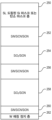
도 1은 일부 실시 예들에 따른, 반도체 칩 제작에 사용하기 위한 플라즈마 프로세싱 시스템을 통한 수직 단면도를 도시한다.
도 2는 본 개시의 구현 예들에 따른, 에칭을 위한 웨이퍼의 일부의 단면을 개념적으로 예시한다.
도 3은 본 개시의 구현 예들에 따른, 고 종횡비 유전체 에칭을 위한 4-상태 RF 펄싱 레짐에 대한 다양한 전력 레짐들을 개념적으로 예시하는 그래프이다.
도 4는 본 개시의 구현 예들에 따른, 4-상태 펄싱된 RF 파형에 대한 RF 전력 대 시간을 개념적으로 예시한다.
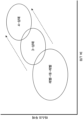
도 5는 본 개시의 구현 예들에 따른, 4-상태 RF 펄싱 구성으로 가능한 개선된 결과들을 개념적으로 예시한다.
도 6은 본 개시의 구현 예들에 따른, 도 1의 제어 시스템의 예시적인 개략도를 도시한다.1 shows a vertical cross-section through a plasma processing system for use in semiconductor chip fabrication, according to some embodiments.
2 conceptually illustrates a cross-section of a portion of a wafer for etching, according to implementations of the present disclosure.
3 is a graph conceptually illustrating various power regimes for a four-state RF pulsing regime for high aspect ratio dielectric etch, according to implementations of the present disclosure.
FIG. 4 conceptually illustrates RF power versus time for a 4-state pulsed RF waveform, according to implementation examples of the present disclosure.
5 conceptually illustrates the improved results possible with a four-state RF pulsing configuration, according to implementation examples of the present disclosure.
Figure 6 shows an example schematic diagram of the control system of Figure 1, according to implementation examples of the present disclosure.
이하의 기술에서, 본 개시의 실시 예들의 이해를 제공하기 위해 수많은 구체적 상세들이 제시된다. 그러나, 본 개시가 이들 구체적인 상세들의 일부 또는 전부 없이 실시될 수도 있다는 것이 당업자들에게 명백할 것이다. 다른 예들에서, 공지의 프로세스 동작들은 본 개시를 불필요하게 모호하게 하지 않도록 상세히 기술되지 않았다.In the following description, numerous specific details are set forth to provide an understanding of embodiments of the present disclosure. However, it will be apparent to those skilled in the art that the present disclosure may be practiced without some or all of these specific details. In other instances, well-known process operations have not been described in detail so as not to unnecessarily obscure the present disclosure.
현재의 최신 고 종횡비 콘택트 (high aspect ratio contact; HARC) 에칭 프로세스들은 3-상태 RF 펄싱을 사용한다. 이 스킴에서, 상태 1은 통상적으로 고 선택도로 고 종횡비 에칭을 용이하게 하는 고 피크 전력 상태이다. 상태 2는 통상적으로 마스크 상에 중성 증착 (neutral deposition) 을 제공하는 실질적으로 제로 ('0') 로 설정되고, 이는 선택도를 개선한다. 상태 3은 보잉 (bowing) 을 완화시키기 위해 패시베이션을 제공하는 레짐 (regime) 에 있거나 미개방 (not-open; NOP) 마진을 개선하는 상이한 레짐에 있도록 선택될 수 있다. 그 결과, 통상적으로 보우 제어 대 선택도 대 미개방 마진을 수반하는 트레이드 오프가 있다. 그러나, 제 4 상태는 고 종횡비 에칭 프로파일을 튜닝하기 위한 부가적인 노브 및 유연성을 제공하고, 이에 대한 요건은 점점 더 엄격해진다.Current state-of-the-art high aspect ratio contact (HARC) etch processes use three-state RF pulsing. In this scheme, state 1 is typically a high peak power state that facilitates high aspect ratio etching with high selectivity. State 2 is typically set to substantially zero ('0') providing neutral deposition on the mask, which improves selectivity. State 3 can be selected to be in a regime that provides passivation to mitigate bowing or to be in a different regime that improves not-open (NOP) margin. As a result, there is a trade-off that typically involves bow control versus selectivity versus unopened margin. However, the fourth state provides additional knobs and flexibility for tuning the high aspect ratio etch profile, the requirements for which become increasingly stringent.
이하에 더 상세히 논의된 바와 같이, 특정적으로 선택된 제 3 상태와 함께 제 4 상태의 부가는 보우 제어, 선택도 및 미개방 마진 사이의 트레이드-오프를 관리하는 데 유연성을 제공한다. 예를 들어, 제 4 상태는 비-개방 마진이 보잉 또는 선택도에 영향을 주지 않고 강화되도록 선택될 수 있다. HARC 에칭과 관련된 특정한 이슈들 (즉, 보잉, 선택도, 미개방 마진) 을 해결할 수 있는 몇몇 전력 레짐들이 식별되었다. 문제 진술 및 목표된 결과에 기초하여, 트레이드 오프의 완화 및 관리를 인에이블하는 펄스 상태들의 조합을 선택할 수 있다. 따라서, 제 4 상태의 사용은 3-상태 펄싱을 사용하여 이전에 가능하지 않은 HARC 에칭과 관련된 이슈들을 해결하도록 사용될 수 있는 부가적인 노브를 제공한다.As discussed in more detail below, the addition of a fourth state along with a specifically selected third state provides flexibility in managing the trade-off between bow control, selectivity, and open margin. For example, the fourth state can be selected such that the non-open margin is enhanced without affecting bowing or selectivity. Several power regimes have been identified that can address specific issues associated with HARC etching (i.e., boing, selectivity, and unopened margin). Based on the problem statement and desired results, a combination of pulse states can be selected that enables mitigation and management of trade-offs. Therefore, use of the fourth state provides an additional knob that can be used to address issues associated with HARC etching that were not previously possible using three-state pulsing.
본 명세서에 기술된 다양한 구현 예들은 플라즈마 프로세싱 시스템에서 수행될 수도 있다. 도 1을 참조하면, 예시적인 플라즈마 처리 시스템 또는 장치는 가스들 (105, 107, 109) (예를 들어, 반응 물질 가스 및 퍼지 가스) 또는 다른 화학 물질을 챔버 (101) 로 분배하기 위한 가스 인젝터/샤워헤드/노즐 (103), 챔버 벽들 (111), 웨이퍼를 척킹 (chucking) 및 디척킹하기 (dechucking) 위한 정전기 전극들을 포함할 수도 있는 프로세싱될 기판 또는 웨이퍼 (115) 를 홀딩하기 위한 척 (113) 을 갖는, 챔버 (101) 를 포함할 수도 있다. 척 (113) 은 열적 제어를 위해 가열되고, 목표된 온도로 기판 (115) 의 가열을 가능하게 한다. Various implementations described herein may be performed in a plasma processing system. 1 , an exemplary plasma processing system or apparatus includes a gas injector for dispensing
일부 구현 예들에서, 척 (113) 은 플라즈마 프로세싱 시스템의 하부 전극을 규정한다 (또는 포함한다). 일부 구현 예들에서, 소스 RF 신호 생성기 (119) 는 기판 (115) 위의 플라즈마 프로세싱 영역 (125) 내에 플라즈마를 생성하도록 하부 전극에 고 주파수 소스 RF 전력을 공급하도록 구성된다. 일부 구현 예들에서, 바이어스 RF 신호 생성기 (117) 는 본 개시의 구현 예들에 따라, 하부 전극에 저 주파수 바이어스 RF 전력을 제공하도록 구성된다. In some implementations,
일부 구현 예들에서, 샤워헤드 (103) 는 플라즈마 프로세싱 시스템의 상부 전극을 규정한다. 일부 구현 예들에서, 소스 RF 전력 또는 바이어스 RF 전력은 상부 전극에 인가된다. 특정한 구현 예들에서, 소스 RF 전력은 상부 전극에 인가되는 한편, 바이어스 RF 전력은 하부 전극에 인가된다.In some implementations,
일부 구현 예들에서, 챔버 벽들은 열 관리 및 효율성을 지지하도록 가열된다. 진공 소스 (127) 가 챔버 (101) 로부터 배기 포트를 통해 가스들을 배기하도록 진공을 제공한다. 시스템 또는 장치는 챔버 압력, 불활성 가스 플로우, 플라즈마 소스 전력, 플라즈마 소스 주파수, 반응성 가스 플로우; 바이어스 전력, 바이어스 주파수, 온도, 진공 설정들; 및 다른 프로세스 조건을 조절하는 것과 같은 챔버 또는 장치의 동작들 중 일부 또는 전부를 제어하기 위한 시스템 제어기 (129) 를 포함할 수도 있다.In some implementations, chamber walls are heated to support thermal management and efficiency. Vacuum
일부 구현 예들에서, 시스템/장치는 기판들을 프로세싱하기 위한 2 개 이상의 챔버를 포함할 수도 있다.In some implementations, the system/apparatus may include two or more chambers for processing substrates.
일부 실시 예들에서, 기판은 제조 절차를 겪는 (undergo) 반도체 웨이퍼이다. 그러나, 다양한 실시 예들에서, 웨이퍼는 본질적으로 플라즈마-기반 제조 프로세스를 겪는 (subject) 임의의 타입의 기판일 수 있다는 것이 이해되어야 한다. 예를 들어, 일부 실시 예들에서, 웨이퍼는 실리콘, 사파이어, GaN, GaAs 또는 SiC, 또는 다른 기판 재료들로 형성된 기판일 수 있고, 그리고 유리 패널들/기판들, 금속 포일들, 금속 시트들, 폴리머 재료들, 등을 포함할 수 있다. 또한, 다양한 실시 예들에서, 웨이퍼는 형태, 형상, 및/또는 사이즈가 가변할 수도 있다. 예를 들어, 일부 실시 예들에서, 웨이퍼는 상부에 집적 회로 디바이스들이 제작되는 원형-형상 반도체 웨이퍼에 대응할 수도 있다. 다양한 실시 예들에서, 원형-형상 웨이퍼는 200 ㎜ (밀리미터), 300 ㎜, 450 ㎜, 또는 또 다른 사이즈의 직경을 가질 수 있다. 또한, 일부 실시 예들에서, 웨이퍼는 다른 형상들 중에서, 평판 디스플레이를 위한 직사각형 기판 등과 같은 비-원형 기판에 대응할 수도 있다.In some embodiments, the substrate is a semiconductor wafer undergoing a manufacturing procedure. However, it should be understood that in various embodiments, a wafer can be essentially any type of substrate that undergoes a plasma-based manufacturing process. For example, in some embodiments, the wafer can be a substrate formed of silicon, sapphire, GaN, GaAs or SiC, or other substrate materials, and glass panels/substrates, metal foils, metal sheets, polymers, etc. It may include materials, etc. Additionally, in various embodiments, the wafer may vary in shape, shape, and/or size. For example, in some embodiments, the wafer may correspond to a circular-shaped semiconductor wafer on which integrated circuit devices are fabricated. In various embodiments, the round-shaped wafer may have a diameter of 200 mm (millimeters), 300 mm, 450 mm, or another size. Additionally, in some embodiments, the wafer may correspond to a non-circular substrate, such as a rectangular substrate for a flat panel display, among other shapes.
일부 구현 예들에서, 플라즈마 프로세싱 시스템의 척은 설비 플레이트 상에 포지셔닝되고 상단 세라믹 층 아래에 배치된 전극을 포함한다. 전극은 온도 제어 유체가 전극의 온도를 제어하고 결국 웨이퍼의 온도를 제어하도록 흐르는 온도 제어 유체 채널들의 배열을 포함할 수 있다. 척은 전극 내의 대응하는 후면 가스 공급 채널들에 유체로 연결된 후면 가스 공급 포트들 (미도시) 의 배열을 포함할 수 있다. 리프트 핀들은 척의 상단 표면에 대해 웨이퍼의 수직 운동을 제공하도록 척의 상단 표면을 통해 연장하도록 구성될 수 있다. In some implementations, the chuck of the plasma processing system is positioned on a fixture plate and includes an electrode disposed below the top ceramic layer. The electrode may include an array of temperature control fluid channels through which the temperature control fluid flows to control the temperature of the electrode and, in turn, the temperature of the wafer. The chuck may include an array of back gas supply ports (not shown) fluidly connected to corresponding back gas supply channels in the electrode. The lift pins may be configured to extend through the top surface of the chuck to provide vertical movement of the wafer relative to the top surface of the chuck.
임피던스 매칭 시스템은 RF 전력이 플라즈마 프로세싱 영역 (125) 내로 송신될 수 있도록 임피던스 매칭을 제공하도록 사이징되고 연결된 커패시터들 및 인덕터들의 배열을 포함한다. 일부 실시 예들에서, 소스 RF 신호 생성기 (119) 는 고 주파수 RF 신호 생성기이고, 바이어스 RF 신호 생성기 (117) 는 저 주파수 RF 신호 생성기이다. 일부 실시 예들에서, 소스 RF 신호 생성기는 약 50 ㎒에서 약 70 ㎒로 연장하는 범위 내, 또는 약 54 ㎒ 내지 약 63 ㎒로 연장하는 범위 내, 또는 약 60 ㎒에서 무선 주파수 신호들을 생성한다. 일부 실시 예들에서, 소스 RF 신호 생성기는 약 5 ㎾ (kiloWatts) 로부터 약 25 ㎾로 연장하는 범위 내, 또는 약 10 ㎾로부터 약 20 ㎾로 연장하는 범위 내, 또는 약 15 ㎾로부터 약 20 ㎾로 연장하는 범위 내, 또는 약 10 ㎾, 또는 약 16 ㎾의 RF 전력을 공급한다. 일부 실시 예들에서, 바이어스 RF 신호 생성기 (117) 는 약 50 ㎑ (kiloHertz) 로부터 약 500 ㎑로 연장하는 범위 내, 또는 약 330 ㎑로부터 약 440 ㎑로 연장하는 범위 내, 또는 약 400 ㎑에서 RF 신호들을 생성한다. 일부 실시 예들에서, 바이어스 RF 신호 생성기는 약 15 ㎾로부터 약 100 ㎾로 연장하는 범위 내에서 RF 전력을 공급한다. 예시적인 실시 예에서, 소스 RF 신호 생성기 (119) 는 약 60 ㎒의 주파수를 갖는 무선 주파수 신호들을 생성하도록 설정되고, 바이어스 RF 신호 생성기 (117) 는 약 400 ㎒의 주파수를 갖는 무선 주파수 신호들을 생성하도록 설정된다.The impedance matching system includes an array of capacitors and inductors sized and connected to provide impedance matching so that RF power can be transmitted into the
플라즈마 프로세싱 시스템 내에서 플라즈마 프로세싱 동작들 동안, 하나 이상의 프로세스 가스(들)는 프로세스 가스 공급 시스템을 통해 플라즈마 프로세싱 영역 (125) 에 공급된다. 또한, 무선 주파수 (radiofrequency; RF) 신호들은 무선 주파수 신호 생성기들, 임피던스 매칭 시스템, 설비 플레이트, 전극에 의해 그리고 세라믹 층을 통해 플라즈마 프로세싱 영역 내로 송신된다. 무선 주파수 신호들은 플라즈마 프로세싱 영역 (125) 내에서 프로세스 가스(들)를 플라즈마로 변환한다. 플라즈마의 이온들 및/또는 반응성 구성 성분들 (constituents) 은 웨이퍼 (W) 상에 존재하는 특정한 재료(들)의 조성 및/또는 형상의 변화를 유발하도록 웨이퍼 (W) 상의 하나 이상의 재료들과 상호 작용한다. During plasma processing operations within a plasma processing system, one or more process gas(es) are supplied to the
도 2는 본 개시의 구현 예들에 따른, 에칭을 위한 웨이퍼의 일부의 단면을 개념적으로 예시한다. 예시된 구현 예에서, 고 종횡비 콘택트 홀들/비아들이 에칭되는 통상적인 DRAM 커패시터 스택 구조를 포함하는, 웨이퍼의 표면 섹션이 개념적으로 도시된다.2 conceptually illustrates a cross-section of a portion of a wafer for etching, according to implementations of the present disclosure. In the illustrated implementation, a surface section of a wafer is conceptually shown, including a typical DRAM capacitor stack structure with high aspect ratio contact holes/vias etched.
도시된 바와 같이, 스택은 상단 실리콘, 도핑된 실리콘 마스크 또는 탄소 마스크 층 (250), 제 1 실리콘 나이트라이드 (SiN) 층 (252), 제 1 (중간) 실리콘 옥사이드 (SiO) 층 (254), 제 2 (박형) SiN 층 (256), 제 2 (하부) SiO 층 (258), 제 3 (박형) SiN 층 (260), 및 텅스텐 (W) 에칭 정지 층 (262) 으로 구성된다. 통상적인 DRAM 디바이스에 대해 스택은 대략 1 내지 1.5 ㎛ 높이일 수도 있고, 이러한 DRAM 디바이스들의 제작은 커패시터들의 제조를 포함하고, 고 종횡비 콘택트 비아들이 스택 내에 에칭되는 커패시터 에칭 프로세스를 수반한다. 커패시터 에칭은 매우 고 종횡비 피처들의 적합한 에칭을 필요로 하는 유전체 에칭 프로세스의 일 예이다. 제한 없이 예로서, 일부 구현 예들에서, 고 종횡비 피처는 대략 60, 70, 80, 90, 또는 100 대 1 이상인 높이-대-폭 비를 갖는 피처이다. As shown, the stack includes a top silicon, a doped silicon mask or
피치 사이즈들이 더 작은 사이즈들로 계속 스케일링되고, 에칭된 피처들의 종횡비가 계속해서 증가함에 따라, 에칭 프로세스에서 결함들에 대해 더 적은 허용 오차가 있다는 것이 인식될 것이다. 커패시터 에칭을 위해, 제한 없이 예로서, 피치 사이즈는 일부 구현 예들에서 50 ㎚ 미만, 일부 구현 예들에서 40 ㎚ 미만, 등일 수 있다. 본 개시의 구현 예들이 DRAM 커패시터 구조체들을 형성하기 위해 HARC 에칭을 참조하여 기술되지만, 이는 매우 고 종횡비 유전체 에칭을 요구하는 피처 맥락의 일 예일 뿐이라는 것이 이해될 것이다. 본 개시의 원리들은 임의의 적용 가능한 디바이스 맥락에서 임의의 고 종횡비 유전체 에칭 (예를 들어, 3D NAND, 예를 들어 메모리 홀 에칭) 에 적용될 수 있다는 것이 이해될 것이다.As pitch sizes continue to scale to smaller sizes and the aspect ratio of etched features continue to increase, it will be appreciated that there is less tolerance for defects in the etching process. For capacitor etching, by way of example and without limitation, the pitch size may be less than 50 nm in some implementations, less than 40 nm in some implementations, etc. Although implementations of the present disclosure are described with reference to a HARC etch to form DRAM capacitor structures, it will be understood that this is only one example of a feature context that requires a very high aspect ratio dielectric etch. It will be understood that the principles of the present disclosure can be applied to any high aspect ratio dielectric etch (e.g., 3D NAND, e.g., memory hole etch) in any applicable device context.
RF 펄싱 기술은 CW (Continuous Wave) 모드에서 동작하는 것으로부터 펄싱 모드 레짐들 (예를 들어, 온-오프, 레벨-대-레벨 (level-to-level)) 로 발전해 왔다. 현재의 최신 RF 펄싱 레짐들은 3-상태 펄싱 스킴을 사용하여 동작한다. 멀티-상태 RF 펄싱의 발전들은 프로세스 마진 대 에칭 선택도, 프로파일 보우 (bow), CD (Critical Dimension) 및 에칭 레이트 균일성을 개선함으로써 고 종횡비 에칭에 개선들을 가능하게 한다. 그러나, 디바이스 사이즈가 계속해서 더 축소되고 피치 사이즈가 더 감소됨에 따라 (예를 들어, 50 ㎚ 이하로), 현재의 최신 3-상태 RF 펄싱 기술 하에서도, 에칭 선택도 대 프로세스 마진 트레이드 오프에서 더 많은 개선들을 달성하기 어렵다. 현재 기술 레짐들은 충분한 프로세스 마진 (예를 들어, 언더-에칭 (under-etch), 미개방 (not open), 캡핑 (capping)) 을 유지하는 동안 고 종횡비 에칭의 건전성을 밸런싱하기 위해 분투한다.RF pulsing technology has evolved from operating in Continuous Wave (CW) mode to pulsing mode regimes (e.g., on-off, level-to-level). Current state-of-the-art RF pulsing regimes operate using a three-state pulsing scheme. Advances in multi-state RF pulsing enable improvements in high aspect ratio etch by improving process margin versus etch selectivity, profile bow, critical dimension (CD), and etch rate uniformity. However, as device sizes continue to shrink further and pitch sizes become further reduced (e.g., below 50 nm), even under current state-of-the-art three-state RF pulsing technology, the etch selectivity versus process margin trade-off becomes more challenging. Many improvements are difficult to achieve. Current technology regimes struggle to balance the soundness of high aspect ratio etching while maintaining sufficient process margins (e.g., under-etch, not open, capping).
RF 펄싱은 고 주파수 RF 신호 (또한 소스 전력으로 공지됨; 예를 들어, 일부 구현 예들에서 약 60 ㎒의 주파수) 및 저 주파수 RF 신호 (또한 바이어스 전력으로 공지됨; 예를 들어, 일부 구현 예들에서 약 400 kHz의 주파수) 에 대한 펄싱된 전력 레벨들의 구현을 수반한다. 예를 들어, 2-상태 RF 펄싱 스킴에서, "상태 1" (또는 "S1") 은 통상적으로 3 keV보다 더 큰 이온 에너지를 갖는, 고 바이어스 전력 및 고 소스 전력 상태, 예를 들어 1 ㎾보다 더 크고, 좁은 이온 에너지 분포 함수 (ion energy distribution function; IADF) 를 획득하기 위한 30 mTorr 미만의 압력에서 동작한다. "상태 0" (또는 "S0") 으로 지칭되는 펄스의 다른 상태는 저/제로 바이어스 및 저/제로 소스 전력, 예를 들어, 1 ㎾보다 더 낮고, 100 eV보다 더 낮은 이온 에너지를 사용하는 증착 단계를 나타낸다. 상태 0은 주로 직접 이온 증착 및 이온 활성화된 중성 증착과 같은 상이한 메커니즘들로 인한 패시베이션을 제공한다. 이러한 RF 펄싱 레짐을 동작시키기 위한 통상적인 펄스 반복 레이트는 약 100 Hz 내지 2 kHz이다. RF pulsing can be performed using a high frequency RF signal (also known as source power; e.g., in some implementations a frequency of about 60 MHz) and a low frequency RF signal (also known as bias power; in some implementations, e.g. It involves the implementation of pulsed power levels for a frequency of about 400 kHz). For example, in a two-state RF pulsing scheme, “State 1” (or “S1”) is a high bias power and high source power state, typically with an ion energy greater than 3 keV, e.g. greater than 1 kW. It operates at pressures below 30 mTorr to obtain a larger, narrower ion energy distribution function (IADF). Another state of the pulse, referred to as "state 0" (or "S0"), is deposition using low/zero bias and low/zero source power, e.g., ion energies lower than 1 kW and lower than 100 eV. Indicates steps. State 0 primarily provides passivation due to different mechanisms such as direct ion deposition and ion activated neutral deposition. Typical pulse repetition rates for operating this RF pulsing regime are about 100 Hz to 2 kHz.
3-상태 펄싱 스킴은 상기 2 개의 상태들을 포함하고, 상태 1은 통상적으로 큰 선택도로 고 종횡비 에칭을 용이하게 하는 고 피크 전력이고, 상태 2는 통상적으로 선택도를 개선하는 마스크 상에 중성 증착을 제공하는 '0'으로 설정된다. 이에 대해, 상태 3은 보잉을 완화하기 위해 패시베이션을 제공하는 레짐에 있거나 미개방 마진을 개선하는 상이한 레짐에 있도록 선택될 수 있다. 따라서, 3-상태 펄싱 레짐에서, 통상적으로 보우 제어 대 선택도 대 미개방 마진을 수반하는 트레이드-오프가 있다. 따라서, 제 3 상태의 부가는 특정한 지점을 넘어 2-상태 RF 펄싱에 비해 이점들을 제공하지만, 이들 트레이드-오프들로 인해 3-상태 펄싱 스킴들에 대한 추가 개선이 가능하지 않다.The three-state pulsing scheme includes the two states, where state 1 is high peak power, which typically facilitates high aspect ratio etching with large selectivity, and state 2 is typically neutral deposition on the mask, which improves selectivity. It is set to '0' provided. In this regard, state 3 can be chosen to be in a regime that provides passivation to alleviate the boing or to be in a different regime that improves the unopened margin. Therefore, in a three-state pulsing regime, there is typically a trade-off involving bow control versus selectivity versus unopened margin. Accordingly, the addition of a third state offers advantages over two-state RF pulsing beyond a certain point, but these trade-offs do not allow further improvement over three-state pulsing schemes.
그러나, 제 4 상태의 특정한 적용 예가 보우 제어, 선택도 및 미개방 마진 사이의 트레이드-오프를 관리하기 위해 목표된 유연성을 제공한다는 것이 발견되었다. 예를 들어, 제 4 상태는 비-개방 마진이 보잉 또는 선택도에 영향을 주지 않고 강화되도록 선택될 수 있다. HARC 에칭과 관련된 특정한 이슈들 (즉, 보잉, 선택도, 미개방 마진) 을 해결할 수 있는 몇몇 전력 레짐들이 식별되었다. 보다 구체적으로, 특정한 제 3 상태와 결합된 제 4 상태는 이전에 3-상태 펄싱으로 가능하지 않은 HARC 에칭과 관련된 이슈들을 해결하기 위해 발견되었다.However, it has been discovered that certain applications of the fourth state provide targeted flexibility to manage the trade-off between bow control, selectivity and open margin. For example, the fourth state can be selected such that the non-open margin is enhanced without affecting bowing or selectivity. Several power regimes have been identified that can address specific issues associated with HARC etching (i.e., boing, selectivity, and unopened margin). More specifically, a fourth state combined with a specific third state was discovered to solve issues associated with HARC etching that were not previously possible with three-state pulsing.
도 3은 본 개시의 구현 예들에 따른, 고 종횡비 유전체 에칭을 위한 4-상태 RF 펄싱 레짐에 대한 다양한 전력 레짐들을 개념적으로 예시하는 그래프이다. 예시된 그래프에서, 4-상태 RF 펄싱 스킴에 대해 도시된 구별된 펄싱된 RF 상태들에 대한 전력 레짐들과 함께, 고 주파수 RF 신호의 전력 대 저 주파수 RF 신호의 전력이 도시된다. 이들 전력 레짐들은 다양한 펄싱된 RF 상태들에 대한 고 주파수 RF 신호 및 저 주파수 RF 신호의 전력 레벨들에 대한 범위들을 규정하고, 다양한 상태들에 대한 고 주파수 RF 신호 및 저 주파수 RF 신호의 전력 레벨들의 관계들 또는 비들을 더 규정한다.3 is a graph conceptually illustrating various power regimes for a four-state RF pulsing regime for high aspect ratio dielectric etch, according to implementations of the present disclosure. In the illustrated graph, the power of the high frequency RF signal versus the power of the low frequency RF signal is shown, with power regimes for the distinct pulsed RF states shown for the four-state RF pulsing scheme. These power regimes define ranges for the power levels of the high-frequency RF signal and low-frequency RF signal for various pulsed RF states, and the power levels of the high-frequency RF signal and low-frequency RF signal for the various states. The relationships or ratios are further defined.
일부 구현 예들에서, 상태 1 (S1) 은 예시된 그래프에 개념적으로 도시된 바와 같이, 전력 레짐 (300) 으로 구성된다. 상태 1은 고 종횡비 에칭을 제공하도록 구성된 고 전력 상태이고, 고 주파수 소스 RF 신호 및 저 주파수 바이어스 RF 신호 모두는 다른 상태들에 비해 고 전력 레벨들에서 동작 (펄싱) 된다. 일부 구현 예들에서, S1 바이어스 (저 주파수 RF) 전력 레벨은 20 ㎾보다 더 큰 범위 내; 일부 구현 예들에서, 약 30 내지 40 ㎾의 범위 내에 있도록 구성된다. 일부 구현 예들에서, S1 소스 (고 주파수 RF) 전력 레벨은 7 ㎾보다 더 큰 범위; 일부 구현 예들에서, 약 8 내지 10 ㎾의 범위 내; 일부 구현 예들에서, 약 9 ㎾에 있도록 구성된다. 일부 구현 예들에서, (S1에 대한) 바이어스 전력 레벨 대 소스 전력 레벨의 비는 대략 3 : 1 내지 4 : 1의 범위이다. 일부 구현 예들에서, S1 듀티 사이클은 (전체 펄싱된 RF 사이클의) 약 3 내지 30 %의 범위이고; 일부 구현 예들에서, 약 7 내지 9 %의 범위이다. In some implementations, state 1 (S1) is comprised of
일반적으로, S1은 펄싱된 RF 사이클의 다른 상태들과 비교하여 바이어스 RF 신호 및 소스 RF 신호에 대해 가장 높은 전력 레벨들을 규정한다. S1은 현재 기술된 바와 같이 낮은 듀티 사이클로 수행될 때 마스크에 고 선택도를 갖는 고 종횡비 에칭을 제공한다. 그러나, S1이 우수한 선택도를 제공할 수 있지만, S1에 대한 트레이드 오프는 잠재적으로 유해한 영향을 받는 개방 마진 및 에칭 프로파일 (예를 들어, SiN 보잉) 이다.Generally, S1 defines the highest power levels for the bias RF signal and the source RF signal compared to other states of the pulsed RF cycle. S1 provides a high aspect ratio etch with high selectivity to the mask when performed at a low duty cycle as currently described. However, while S1 can provide superior selectivity, the trade-off for S1 is the potentially detrimental impact of open margins and etch profiles (eg, SiN bowing).
일부 구현 예들에서, 상태 2 (S2) 는 전력 레짐 (302) 으로 구성된다. 도시된 바와 같이, S2는 소스 RF 신호 및 바이어스 모두가 S1과 비교하여 상대적으로 저 전력 레벨들에서 동작되는, 다른 상태들과 비교하여 저 전력 상태이다. 일부 구현 예들에서, S2 바이어스 (저 주파수 RF) 전력 레벨은 약 0.5 ㎾ 내지 5 ㎾의 범위; 일부 구현 예들에서, 약 1 ㎾ 내지 3 ㎾의 범위 내로 구성된다. 일부 구현 예들에서, S2 소스 (고 주파수 RF) 전력 레벨은 약 2 ㎾ 내지 7 ㎾의 범위; 일부 구현 예들에서 약 3 내지 5 ㎾의 범위 내로 구성된다. In some implementations, state 2 (S2) is comprised of
일부 구현 예들에서, S2 바이어스 전력 레벨은 S1 바이어스 전력 레벨의 약 1 내지 20 %의 범위; 일부 구현 예들에서, 약 4 내지 9 %; 일부 구현 예들에서 약 5 내지 7 % 내에 있도록 구성된다. 일부 구현 예들에서, S2 소스 전력 레벨은 S1 소스 전력 레벨의 약 20 내지 70 %의 범위; 일부 구현 예들에서, 약 25 내지 55 %; 일부 구현 예들에서 약 30 내지 40 % 내에 있도록 구성된다.In some implementations, the S2 bias power level ranges from about 1 to 20% of the S1 bias power level; In some embodiments, about 4-9%; In some embodiments it is configured to be within about 5 to 7%. In some implementations, the S2 source power level ranges from about 20 to 70% of the S1 source power level; In some embodiments, about 25 to 55%; In some embodiments it is configured to be within about 30 to 40%.
S1과 달리, S2는 바이어스 전력 레벨이 소스 전력 레벨보다 더 작도록 구성된다. 일부 구현 예들에서, (S2에 대한) 바이어스 전력 레벨 대 소스 전력 레벨의 비는 대략 1 : 1 내지 1 : 2의 범위 내이고; 일부 구현 예들에서, 비는 약 0.8 미만이다. Unlike S1, S2 is configured such that the bias power level is less than the source power level. In some implementations, the ratio of bias power level (for S2) to source power level is approximately in the range of 1:1 to 1:2; In some implementations, the ratio is less than about 0.8.
일부 구현 예들에서, S2 듀티 사이클은 전체 사이클의 약 3 내지 30 % 범위 내이고; 일부 구현 예들에서, 약 10 내지 20 %의 범위 내; 일부 구현 예들에서, 약 15 %이다.In some implementations, the S2 duty cycle ranges from about 3 to 30% of the total cycle; In some embodiments, within the range of about 10-20%; In some implementations, it is about 15%.
제한 없이 예로서, 일부 구현 예들에서, 대략 3 ㎾의 S2 바이어스 전력 레벨에 대해, S2 소스 전력 레벨은 대략 5 ㎾이고; 대략 1.5 ㎾의 S2 바이어스 전력 레벨에 대해, S2 소스 전력 레벨은 대략 2.5 ㎾이다.By way of example and not limitation, in some implementations, for an S2 bias power level of approximately 3 kW, the S2 source power level is approximately 5 kW; For an S2 bias power level of approximately 1.5 kW, the S2 source power level is approximately 2.5 kW.
일부 구현 예들에서, 상태 2 펄스 구성은 넥의 트리밍을 제공하여, 개방 마진을 개선한다. 그러나, S2에 대한 트레이드 오프는 마스크에 대한 감소된 선택도이다.In some implementations, the state 2 pulse configuration provides trimming of the neck to improve open margin. However, the trade-off for S2 is reduced selectivity to the mask.
일부 구현 예들에서, 상태 3 (S3) 은 예시된 그래프에 개념적으로 도시된 바와 같이, 전력 레짐 (304) 에서 동작하도록 구성된다. 상태 3은 중간-전력 상태로서 구성되고, 고 주파수 소스 RF 신호 및 저 주파수 바이어스 RF 신호 모두는 대략 상태 1과 상태 2 사이인 중간-전력 레벨들에서 동작된다. 일부 구현 예들에서, S3 바이어스 (저 주파수 RF) 전력 레벨은 약 10 내지 24 ㎾의 범위; 일부 구현 예들에서, 약 14 내지 20 ㎾의 범위; 일부 구현 예들에서, 약 16 내지 18 ㎾ 내로 구성된다. 일부 구현 예들에서, S3 소스 (고 주파수 RF) 전력 레벨은 약 3 내지 7 ㎾의 범위 내; 일부 구현 예들에서, 약 4 내지 6 ㎾; 일부 구현 예들에서, 약 5 ㎾로 구성된다. In some implementations, state 3 (S3) is configured to operate in
일반적으로, S3 바이어스 전력 레벨 및 소스 전력 레벨은 S1과 S2 사이이다. 일부 구현 예들에서, S3 바이어스 전력 레벨은 S1 바이어스 전력 레벨의 약 30 내지 70 %의 범위 내; 일부 구현 예들에서, 약 40 내지 60 %의 범위 내; 일부 구현 예들에서, 약 50 %이다. 일부 구현 예들에서, S3 소스 전력 레벨은 S1 소스 전력 레벨의 약 30 내지 80 % 범위이고; 일부 구현 예들에서, 약 40 내지 70 %의 범위; 일부 구현 예들에서, 약 50 내지 60 %의 범위이다.Typically, the S3 bias power level and source power level are between S1 and S2. In some implementations, the S3 bias power level ranges from about 30 to 70% of the S1 bias power level; In some embodiments, within the range of about 40 to 60%; In some implementations, it is about 50%. In some implementations, the S3 source power level ranges from about 30 to 80% of the S1 source power level; In some embodiments, ranging from about 40 to 70%; In some embodiments, it ranges from about 50 to 60%.
일부 구현 예들에서, (S3에 대한) 바이어스 전력 레벨 대 소스 전력 레벨의 비는 대략 1.3 : 1 내지 3 : 1의 범위이다. 따라서 제한 없이 예로서, 12 ㎾의 바이어스 전력 레벨에 대해, 소스 전력 레벨은 일부 구현 예들에서 약 7 ㎾일 수 있다. 또는 14 ㎾의 바이어스 전력 레벨에 대해, 바이어스 전력 레벨은 일부 구현 예들에서 약 9 ㎾일 수 있다. 이들은 비들의 범위 내에 있는 다른 전력 레벨들이 S3에 대해 가능하기 때문에, 제한 없이 예로서 제공된다. 일부 구현 예들에서, S3에 대한 바이어스 전력 레벨 및 소스 전력 레벨의 비는 S1의 비와 유사하지만, S3은 S1과 비교하여 더 낮은 전력 레벨들로 구성된다.In some implementations, the ratio of bias power level (for S3) to source power level ranges from approximately 1.3:1 to 3:1. Thus, by way of example and not limitation, for a bias power level of 12 kW, the source power level may be about 7 kW in some implementations. or for a bias power level of 14 kW, the bias power level may be about 9 kW in some implementations. These are provided as examples without limitation, since other power levels within the range of ratios are possible for S3. In some implementations, the ratio of bias power level and source power level for S3 is similar to that of S1, but S3 is comprised of lower power levels compared to S1.
일부 구현 예들에서, S3 듀티 사이클은 전체 RF 펄싱 사이클의 약 3 내지 30 % 범위이고; 일부 구현 예들에서, 약 15 내지 25 %의 범위; 일부 구현 예들에서, 약 20 %이다.In some implementations, the S3 duty cycle ranges from about 3 to 30% of the total RF pulsing cycle; In some embodiments, in the range of about 15 to 25%; In some implementations, it is about 20%.
일부 구현 예들에서, S3는 상대적인 의미에서 매우 우수한 선택도 및 합리적으로 우수한 옥사이드 및 나이트라이드 프로파일을 제공하도록 구성된 중간-전력 에칭 상태로서 구성되지만, S3의 트레이드 오프는 네킹 이슈들 (necking issues) 로 인한 개방 마진이다. S1과 비교하여, S3은 유사한 선택도를 제공하지만 감소된 SiN 보잉 및 감소된 옥사이드 보잉의 관점에서 개선된 에칭 프로파일을 제공하도록 구성될 수 있다.In some implementations, S3 is configured as a mid-power etch state configured to provide very good selectivity in a relative sense and reasonably good oxide and nitride profiles, but the trade-off of S3 is due to necking issues. It is an open margin. Compared to S1, S3 provides similar selectivity but can be configured to provide an improved etch profile in terms of reduced SiN bowing and reduced oxide bowing.
일부 구현 예들에서, 상태 4 (S4) 는 실질적으로 0의 전력 상태 또는 매우 낮은 전력 상태로서 동작되고, 고 주파수 RF 신호 및 저 주파수 RF 신호 각각은 실질적으로 0의 전력 레벨, 또는 거의 0 또는 그렇지 않으면 S2보다 실질적으로 더 낮은 전력 레벨으로 설정된다. 일부 구현 예들에서, S4 바이어스 전력은 약 0 내지 1 ㎾의 범위 내이고; 한편, 일부 구현 예들에서, S4 소스 전력은 약 0 내지 1 ㎾의 범위 내이다. 일부 구현 예들에서, 상태 4는 상기 주지된 바와 같이, 마스크 상에 중성 증착을 제공하고, 이에 따라 선택도를 개선하는 상태 0 (S0) 으로 지칭된다. 일부 구현 예들에서, S4 듀티 사이클은 전체 펄싱된 RF 사이클의 약 35 내지 75 % 범위 내; 일부 구현 예들에서, 약 45 내지 65 %의 범위 내; 일부 구현 예들에서, 약 50 내지 60 %의 범위 내이다.In some implementations, state 4 (S4) is operated as a substantially zero power state or a very low power state, wherein the high frequency RF signal and the low frequency RF signal each have a power level of substantially zero, or near zero or otherwise. It is set to a substantially lower power level than S2. In some implementations, the S4 bias power ranges from about 0 to 1 kW; Meanwhile, in some implementations, the S4 source power ranges from about 0 to 1 kW. In some implementations, state 4 is referred to as state 0 (S0), which, as noted above, provides neutral deposition on the mask, thereby improving selectivity. In some implementations, the S4 duty cycle ranges from about 35 to 75% of the total pulsed RF cycle; In some embodiments, within the range of about 45 to 65%; In some embodiments, it is in the range of about 50-60%.
일부 구현 예들에서, S4는 중성 증착을 제공하도록 구성된다.In some implementations, S4 is configured to provide neutral deposition.
4-상태 RF 펄싱 스킴의 상태들 S1, S2, S3, 및 S4를 기술하였지만, 대표적인 펄싱된 파형이 이제 예시를 목적으로 기술된다.Although states S1, S2, S3, and S4 of the four-state RF pulsing scheme have been described, a representative pulsed waveform is now described for illustrative purposes.
도 4는 본 개시의 구현 예들에 따른, 4-상태 펄싱된 RF 파형에 대한 RF 전력 대 시간을 개념적으로 예시한다. 4-상태 펄싱된 RF 파형의 예를 예시할 목적으로 2 개의 완전한 사이클들이 도시된다.FIG. 4 conceptually illustrates RF power versus time for a 4-state pulsed RF waveform, according to implementation examples of the present disclosure. Two complete cycles are shown for the purpose of illustrating an example of a 4-state pulsed RF waveform.
예시된 구현 예에 도시된 바와 같이, S1은 저 주파수 (바이어스) RF 신호 및 고 주파수 (소스) RF 신호가 펄싱된 RF 사이클의 가장 높은 전력 레벨들을 갖도록 (펄싱되는) 고 피크 전력 상태이다. 예시된 구현 예에서, 바이어스 RF 신호 대 소스 RF 신호의 전력 레벨들의 비는 약 2 : 1이다. 그러나, 상기 주지된 바와 같이, 이 비는 상이한 구현 예들에 따라 가변할 수 있다. S1의 듀티 사이클은 짧고, 예를 들어 총 RF 펄싱 사이클 지속 기간의 약 3 내지 10 %이다.As shown in the illustrated implementation, S1 is a high peak power state such that the low frequency (bias) RF signal and the high frequency (source) RF signal are (pulsed) to have the highest power levels of the pulsed RF cycle. In the illustrated implementation, the ratio of power levels of the bias RF signal to the source RF signal is approximately 2:1. However, as noted above, this ratio may vary depending on different implementations. The duty cycle of S1 is short, for example about 3 to 10% of the total RF pulsing cycle duration.
S2는 RF 펄싱 사이클에서 S1을 따르고, 바이어스 신호 및 소스 신호가 상대적으로 저 전력 레벨들을 갖는 (펄싱되는) 저 전력 상태이다. 일부 구현 예들에서, S3 동안 바이어스 신호 및/또는 소스 신호의 전력 레벨들은 S4를 제외하고 사이클 중 가장 낮다. 일부 구현 예들에서, 바이어스 전력 대 소스 전력의 비는 1보다 더 작다. 상이한 구현 예들에서, 상기 나타낸 바와 같이 S2에 대해 다양한 전력 비들이 가능하다. S2의 듀티 사이클은 예시된 구현 예에서 도시된 바와 같이 S1의 듀티 사이클과 유사할 수 있지만, 또한 이전에 논의된 바와 같이 S1의 듀티 사이클보다 더 클 수 있다.S2 follows S1 in the RF pulsing cycle and is a low power state where the bias signal and source signal have relatively low power levels (pulsed). In some implementations, the power levels of the bias signal and/or source signal during S3 are the lowest during the cycle except for S4. In some implementations, the ratio of bias power to source power is less than 1. In different implementations, various power ratios are possible for S2 as indicated above. The duty cycle of S2 may be similar to that of S1 as shown in the illustrated implementation, but may also be greater than that of S1 as previously discussed.
S3은 펄싱 사이클에서 S2에 이어지고, 중간 전력 상태로서 구성된다. 즉, 바이어스 신호 및 소스 신호의 전력 레벨들은 S1보다 더 작지만, S2보다 더 크다. 예시된 구현 예에서, S3에 대한 바이어스 신호 및 소스 신호의 전력 레벨들의 비는 대략 3 : 2이다. S3에 대한 바이어스 신호 및 소스 신호의 전력 레벨들의 비는 일부 구현 예들에서 S1의 전력 레벨들과 유사할 수 있다. 다른 구현 예들에서, 이전에 논의된 바와 같이 S3에 대해 다른 비들이 가능하다. 일반적으로, S3의 듀티 사이클은 일부 구현 예들에서 S1보다 더 크다.S3 follows S2 in the pulsing cycle and is configured as an intermediate power state. That is, the power levels of the bias signal and source signal are smaller than S1, but greater than S2. In the illustrated implementation, the ratio of power levels of the bias signal and source signal for S3 is approximately 3:2. The ratio of the power levels of the bias signal and source signal for S3 may be similar to the power levels of S1 in some implementations. In other implementations, other ratios are possible for S3 as previously discussed. In general, the duty cycle of S3 is larger than that of S1 in some implementations.
S4는 펄싱 사이클에서 S3을 따르고, 제로 전력 상태로서 구성되고, 바이어스 신호 및 소스 신호의 전력 레벨들은 0 또는 실질적으로 0이다. 즉, S4 동안, 바이어스 신호 및 소스 신호에 대해 RF 신호 생성기들에 의해 능동적으로 인가되는 RF 전력이 없다. S4는 다양한 상태들 중 가장 긴 듀티 사이클을 갖는다. 일부 구현 예들에서, S4의 듀티 사이클은 펄싱된 RF 사이클의 총 지속 기간의 절반보다 더 크거나, 다른 상태들의 결합된 듀티 사이클보다 더 크다.S4 follows S3 in the pulsing cycle and is configured as a zero power state, where the power levels of the bias signal and source signal are zero or substantially zero. That is, during S4, there is no RF power actively applied by the RF signal generators for the bias signal and source signal. S4 has the longest duty cycle among the various states. In some implementations, the duty cycle of S4 is greater than half the total duration of the pulsed RF cycle, or greater than the combined duty cycle of the other states.
예시된 구현 예에서, 상태들은 다음 순서로 반복적으로 순환된다: S1 → S2 → S3 → S4. 그러나, 일부 구현 예들에서, 상태들은 다음과 같은 다른 순서들로 반복적으로 순환된다: S1 → S2 → S4 → S3; 또는, S1 → S4 → S2 → S3. In the illustrated implementation, the states cycle repeatedly in the following order: S1 → S2 → S3 → S4. However, in some implementations, the states are cycled iteratively in different orders: S1 → S2 → S4 → S3; Or, S1 → S4 → S2 → S3.
본 개시에 기술된 바와 같은 4-상태 RF 펄싱 스킴의 구현은 현재의 최신 HARC 에칭에 사용된 3-상태 RF 펄싱에 대해 개선된 결과들을 제공한다. 3-상태 펄싱된 RF 파형에서, 상태 S1 및 상태 S0이 존재할 것이지만, 제 3 상태는 S2 또는 S3과 유사한 레짐 중 하나로부터 선택될 것이고, 수반되는 트레이드-오프들은 완화되지 않는다. 또한, S2와 S3 사이의 전력 레벨들을 선택하는 것은 현재 개시된 4-상태 RF 펄싱 스킴의 개선된 결과들을 제공하지 않는다.Implementation of a 4-state RF pulsing scheme as described in this disclosure provides improved results over the 3-state RF pulsing used in current state-of-the-art HARC etch. In a three-state pulsed RF waveform, there will be state S1 and state S0, but the third state will be selected from either a regime similar to S2 or S3, and the trade-offs involved are not mitigated. Additionally, choosing power levels between S2 and S3 does not provide improved results of the currently disclosed four-state RF pulsing scheme.
도 5는 본 개시의 구현 예들에 따른, 4-상태 RF 펄싱 구성으로 가능한 개선된 결과들을 개념적으로 예시한다. 5 conceptually illustrates the improved results possible with a four-state RF pulsing configuration, according to implementation examples of the present disclosure.
예시된 그래프에서, 마스크 두께 (예를 들어 R-폴리실리콘 (nm)) 대 하단-대-상단 임계 치수 비 (B/T 비) 가 다양한 RF 펄싱 레짐에 대해 도시된다. 마스크 두께는 에칭 프로세스의 선택도를 나타내고, B/T 비는 에칭된 프로파일 (예를 들어, 테이퍼링 양 또는 종횡비 종속 에칭 (aspect ratio dependent etch; ARDE)) 을 나타낸다. B/T 비는 일반적으로 테이퍼링 및 ARDE로 인해 1보다 더 작고, 개선 사항은 B/T 비를 1로 이동시킨다. 통상적으로, B/T 비에 대한 트레이드 오프는 마스크 두께이다. 즉, 하단 CD가 상단 CD에 접근하도록 하단을 개방하기 위해, 에칭 프로세스는 통상적으로 마스크 두께를 희생해야 한다. 그러나, 본 개시의 구현 예들에 따른 4-상태 RF 펄싱을 활용함으로써, B/T 비 및 마스크 두께의 개선들을 동시에 달성하는 것이 가능하다. In the illustrated graph, mask thickness (e.g. R-polysilicon (nm)) versus bottom-to-top critical dimension ratio (B/T ratio) is shown for various RF pulsing regimes. The mask thickness indicates the selectivity of the etching process, and the B/T ratio indicates the etched profile (eg, the amount of tapering or aspect ratio dependent etch (ARDE)). The B/T ratio is typically less than 1 due to tapering and ARDE, and improvements move the B/T ratio toward 1. Typically, the tradeoff for B/T ratio is mask thickness. That is, to open the bottom so that the bottom CD can access the top CD, the etch process typically has to sacrifice mask thickness. However, by utilizing four-state RF pulsing according to implementation examples of the present disclosure, it is possible to simultaneously achieve improvements in B/T ratio and mask thickness.
도시된 바와 같이, 레벨-대-레벨 RF 펄싱은 가장 낮은 양의 남아 있는 마스크 두께 및 가장 낮은 B/T 비를 제공한다. 결과들은 증가된 마스크 두께 및 증가된 B/T 비를 제공하는 3-상태 RF 펄싱으로 개선된다. 그러나, 이는 선택도 및 에칭 프로파일에 대한 개선을 나타내지만, 특정한 지점을 넘어 다른 것에 대한 트레이드-오프 없이 선택도 또는 에칭 프로파일에 대한 추가 개선을 달성할 수 없다.As shown, level-to-level RF pulsing provides the lowest amount of remaining mask thickness and lowest B/T ratio. Results are improved with three-state RF pulsing providing increased mask thickness and increased B/T ratio. However, while this represents an improvement in selectivity and etch profile, beyond a certain point further improvements in selectivity or etch profile cannot be achieved without trade-offs to the other.
그러나 예시된 그래프에 도시된 바와 같이, 본 개시의 구현 예들에 따른 4-상태 RF 펄싱은 선택도 및 에칭 프로파일 모두에 대한 개선을 가능하게 하여, HARC 에칭 프로세스의 3-상태 RF 펄싱의 현재 트레이드-오프 제한을 파괴하고, 능력들을 확장한다. 일부 구현 예들에서, 이는 마스크 두께를 복구하도록 구성되는 4-상태 RF 펄싱 사이클의 상태 S1 및 상태 S3에 의해 달성되는 한편, S2 및 S4는 에칭된 피처에서 보잉을 패시베이팅하도록 구성된다. 선택도 및 에칭 프로파일을 동시에 개선하기 위한 현재 기술된 4-상태 RF 펄싱 스킴의 능력은 이전에 가능한 것보다 더 큰 디바이스 수율로, 더 낮은 피치 사이즈들에서 더 높은 종횡비 에칭을 가능하게 한다.However, as shown in the illustrated graph, four-state RF pulsing according to implementations of the present disclosure enables improvements in both selectivity and etch profile, compared to the current trade-off of three-state RF pulsing in the HARC etch process. Break down limitations and expand your abilities. In some implementations, this is achieved by states S1 and S3 of a four-state RF pulsing cycle configured to restore mask thickness, while S2 and S4 are configured to passivate bowing in the etched feature. The ability of the currently described four-state RF pulsing scheme to simultaneously improve selectivity and etch profile enables higher aspect ratio etch at lower pitch sizes, with greater device yield than previously possible.
본 개시에 기술된 임의의 방법들은 제어 시스템 (120) 에 의해 자동으로 실행되도록 구현될 수 있다는 것이 이해될 것이다. 일부 구현 예들에서, 제어 시스템과 연관된 사용자 인터페이스는 상기 기술된 구현 예들에 따라 사용자로 하여금 에칭 프로세스의 다양한 양태들을 제어할 수 있도록 구성된다. 제한 없이 예로서, 이들은 RF 펄싱 사이클의 상이한 상태들의 전력 레벨들 및 듀티 사이클들을 설정하기 위한 인터페이스 제어들을 포함할 수도 있다. 일부 구현 예들에서, 특정한 설정들이 사용자-정의될 때, 다른 설정들은 사용자-정의된 설정들에 기초하여 시스템에 의해 자동으로 결정될 수 있고, 이러한 자동으로 결정된 설정들은 사용자에 의해 더 커스터마이징될 (customize) 수도 있고 커스터마이징되지 않을 수도 있다. 예를 들어, 일부 구현 예들에서, S1에 대한 전력 레벨들 및 듀티 사이클들이 사용자-정의될 때, S2 및 S3에 대한 전력 레벨들 및 듀티 사이클들은 S1에 기초하여 자동으로 결정된다. 일부 구현 예들에서, S2 및 S3의 전력 레벨들 및 듀티 사이클들은 S1의 함수들로서 결정된다. 일부 구현 예들에서, 이러한 기능들은 사용자-정의되거나 사용자 인터페이스를 통해 커스터마이징될 수 있다. 일부 구현 예들에서, 사용자 인터페이스는 사용의 용이성을 위해 추상화될 수 있는 미리 규정된 범위 내에서 커스터마이제이션을 제공한다. 예를 들어, S3의 전력 레벨은 S1 전력 레벨의 30 내지 70 %의 범위 사이에서 S3 전력 레벨을 조정하는, 사용자 인터페이스에 의해 제공된 임의의 스케일 (예를 들어 1 내지 10) 을 따라 조정된다.It will be appreciated that any of the methods described in this disclosure may be implemented to be automatically executed by
도 6은 일부 실시 예들에 따른, 도 1의 제어 시스템 (120) 의 예시적인 개략도를 도시한다. 일부 실시 예들에서, 제어 시스템 (120) 은 플라즈마 프로세싱 시스템 (100) 에서 수행된 반도체 제조 프로세스를 제어하기 위한 프로세스 제어기로서 구성된다. 다양한 실시 예들에서, 제어 시스템 (120) 은 프로세서 (1401), 저장 하드웨어 유닛 (HU) (1403) (예를 들어, 메모리), 입력 HU (1405), 출력 HU (1407), 입력/출력 (I/O) 인터페이스 (1409), I/O 인터페이스 (1411), NIC (Network Interface Controller) (1413), 및 데이터 통신 버스 (1415) 를 포함한다. 프로세서 (1401), 저장 HU (1403), 입력 HU (1405), 출력 HU (1407), I/O 인터페이스 (1409), I/O 인터페이스 (1411), 및 NIC (1413) 는 데이터 통신 버스 (1415) 에 의해 서로 데이터 통신한다. 입력 HU (1405) 는 다수의 외부 디바이스들로부터 데이터 통신을 수신하도록 구성된다. 입력 HU (1405) 의 예들은 데이터 획득 시스템, 데이터 획득 카드, 등을 포함한다. 출력 HU (1407) 는 다수의 외부 디바이스들로 데이터를 송신하도록 구성된다. 출력 HU (1407) 의 예들은 디바이스 제어기이다. NIC (1413) 의 예들은 네트워크 인터페이스 카드, 네트워크 어댑터, 등을 포함한다. I/O 인터페이스들 (1409 및 1411) 각각은 I/O 인터페이스에 커플링된 상이한 하드웨어 유닛들 사이의 호환성을 제공하도록 규정된다. 예를 들어, I/O 인터페이스 (1409) 는 입력 HU (1405) 로부터 수신된 신호를 데이터 통신 버스 (1415) 와 호환 가능한 형태, 진폭, 및/또는 속도로 변환하도록 규정될 수 있다. 또한, I/O 인터페이스 (1411) 는 데이터 통신 버스 (1415) 로부터 수신된 신호를 출력 HU (1407) 와 호환 가능한 형태, 진폭, 및/또는 속도로 변환하도록 규정될 수 있다. 다양한 동작들이 제어 시스템 (120) 의 프로세서 (1401) 에 의해 수행되는 것으로 본 명세서에 기술되지만, 일부 실시 예들에서 다양한 동작들이 제어 시스템 (120) 의 복수의 프로세서들에 의해 그리고/또는 제어 시스템 (120) 과 데이터 통신하는 데이터 내의 복수의 컴퓨팅 시스템들의 복수의 프로세서들에 의해 수행될 수 있다는 것이 이해되어야 한다.FIG. 6 shows an example schematic diagram of the
일부 실시 예들에서, 제어 시스템 (120) 은 센싱된 값들에 부분적으로 기초하여 다양한 웨이퍼 제조 시스템들의 디바이스들을 제어하도록 채용된다. 예를 들어, 제어 시스템 (120) 은 센싱된 값들 및 다른 제어 파라미터들에 기초하여 밸브들 (1417), 필터 히터들 (1419), 웨이퍼 지지 구조체 히터들 (1421), 펌프들 (1423), 및 기타 디바이스들 (1425) 중 하나 이상을 제어할 수도 있다. 밸브들 (1417) 은 후면 가스 공급 시스템 (129), 프로세스 가스 공급 시스템 (191), 및 온도 제어 유체 순환 시스템 (125) 의 제어와 연관된 밸브들을 포함할 수 있다. 제어 시스템 (120) 은 예를 들면, 압력 마노미터들 (1427), 플로우 미터들 (1429), 온도 센서들 (1431), 및/또는 기타 센서들 (1433), 예를 들어, 전압 센서들, 전류 센서들, 등으로부터 센싱된 값들을 수신한다. 제어 시스템 (120) 은 또한 웨이퍼 (W) 상에서 플라즈마 프로세싱 동작들의 수행 동안 플라즈마 프로세싱 시스템 (100) 내 프로세스 조건들을 제어하도록 채용될 수도 있다. 예를 들어, 제어 시스템 (120) 은 프로세스 가스 공급 시스템 (191) 으로부터 플라즈마 프로세싱 영역 (182) 에 공급된 프로세스 가스(들)의 타입 및 양들을 제어할 수 있다. 또한, 제어 시스템 (120) 은 RF 신호 생성기들, 임피던스 매칭 시스템 (143) 의 동작을 제어할 수 있다. 또한, 제어 시스템 (120) 은 클램핑 전극(들)을 위한 DC 공급부 (117) 의 동작을 제어할 수 있다. 제어 시스템 (120) 은 또한 리프트 핀들을 위한 리프팅 디바이스들의 동작 및 챔버 도어의 동작을 제어할 수 있다. 제어 시스템 (120) 은 또한 후면 가스 공급 시스템 및 온도 제어 유체 순환 시스템의 동작을 제어한다. 제어 시스템 (120) 은 플라즈마 프로세싱 시스템 (100) 내 임의의 기능의 프로그래밍된 및/또는 수동 제어를 제공하도록 구비된다는 것이 이해되어야 한다.In some embodiments,
일부 실시 예들에서, 제어 시스템 (120) 은 프로세스 타이밍, 프로세스 가스 전달 시스템 온도, 및 압력 차들, 밸브 포지션들, 프로세스 가스들의 혼합물, 프로세스 가스 플로우 레이트, 후면 냉각 가스 플로우 레이트, 챔버 압력, 챔버 온도, 웨이퍼 지지 구조체 온도 (웨이퍼 온도), RF 전력 레벨들, RF 주파수들, RF 펄싱, 임피던스 매칭 시스템 설정들, 캔틸레버 암 어셈블리 포지션, 바이어스 전력, 및 특정한 프로세스의 다른 파라미터들을 제어하기 위한 인스트럭션들의 세트들을 포함하는 컴퓨터 프로그램들을 실행하도록 구성된다. 제어 시스템 (120) 과 연관된 메모리 디바이스들 상에 저장된 다른 컴퓨터 프로그램들이 일부 실시 예들에서 채용될 수도 있다. 또한, 일부 실시 예들에서, 제어 시스템 (120) 과 연관된 사용자 인터페이스가 있다. 사용자 인터페이스는 디스플레이 (1435) (예를 들어, 장치 및/또는 프로세스 조건들의 디스플레이 스크린 및/또는 그래픽 소프트웨어 디스플레이들), 및 포인팅 디바이스들, 키보드들, 터치 스크린들, 마이크로폰들, 등과 같은 사용자 입력 디바이스들 (1437) 을 포함한다.In some embodiments,
제어 시스템 (120) 의 동작을 지시하기 위한 소프트웨어는 많은 상이한 방식들로 설계되거나 구성될 수도 있다. 프로세스 시퀀스로 다양한 웨이퍼 제조 프로세스들을 실행하도록 제어 시스템 (120) 의 동작을 지시하기 위한 컴퓨터 프로그램들은 임의의 종래의 컴퓨터 판독 가능 프로그래밍 언어, 예를 들어, 어셈블리 언어, C, C ++, Pascal, Fortran 또는 다른 언어들로 작성될 수 있다. 컴파일링된 객체 코드 또는 스크립트는 프로그램에서 식별된 태스크들을 수행하도록 프로세서 (1401) 에 의해 실행된다. 제어 시스템 (120) 은 예를 들어, 필터 압력 차들, 프로세스 가스 조성 및 플로우 레이트들, 후면 냉각 가스 조성 및 플로우 레이트들, 온도, 압력, RF 전력 레벨들 및 RF 주파수들, 바이어스 전압, 냉각 가스/유체 압력, 및 챔버 벽 온도로서, 특히 플라즈마 조건들과 같은 프로세스 조건들과 관련된 다양한 프로세스 제어 파라미터들을 제어하도록 프로그래밍될 수 있다. 웨이퍼 제조 프로세스 동안 모니터링될 수도 있는 센서들의 예들은 이로 제한되는 것은 아니지만, 질량 유량 제어 모듈들, 압력 센서들, 예컨대 압력 마노미터들 (1427) 및 온도 센서들 (1431) 을 포함한다. 적절하게 프로그래밍된 피드백 및 제어 알고리즘들은 목표된 프로세스 조건들을 유지하기 위해 하나 이상의 프로세스 제어 파라미터들을 제어/조정하도록 이들 센서들로부터의 데이터와 함께 사용될 수도 있다.Software for directing the operation of
일부 구현 예들에서, 제어 시스템 (120) 은 더 광범위한 (broader) 제조 제어 시스템의 일부이다. 이러한 제조 제어 시스템들은, 웨이퍼 프로세싱을 위한 프로세싱 툴들, 챔버들, 및/또는 플랫폼들, 및/또는 웨이퍼 페데스탈, 가스 플로우 시스템, 등과 같은 특정 프로세싱 컴포넌트들을 포함하는, 반도체 프로세싱 장비를 포함할 수 있다. 이들 제조 제어 시스템들은 웨이퍼의 프로세싱 이전에, 프로세싱 동안에 그리고 프로세싱 이후에 그들의 동작을 제어하기 위한 전자 장치와 통합될 수도 있다. 제어 시스템 (120) 은 제조 제어 시스템의 다양한 컴포넌트들 또는 하위부분들을 제어할 수도 있다. 제어 시스템 (120) 은, 웨이퍼 프로세싱 요건들에 따라, 프로세싱 가스들의 전달, 후면 냉각 가스들의 전달, 온도 설정들 (예를 들어, 가열 및/또는 냉각), 압력 설정들, 진공 설정들, 전력 설정들, RF 생성기 설정들, RF 매칭 회로 설정들, 주파수 설정들, 플로우 레이트 설정들, 유체 전달 설정들, 포지션 및 동작 설정들, 툴 및 다른 이송 툴들 및/또는 특정 시스템과 연결되거나 인터페이싱된 로드 록들 내외로의 웨이퍼 이송들을 포함하는, 본 명세서에 개시된 프로세스들 중 임의의 프로세스들을 제어하도록 프로그래밍될 수도 있다.In some implementations,
일반적으로 말하면, 제어 시스템 (120) 은 인스트럭션들을 수신하고, 인스트럭션들을 발행하고, 동작을 제어하고, 웨이퍼 프로세싱 동작들을 인에이블하고, 엔드 포인트 측정들을 인에이블하는, 등을 하는 다양한 집적 회로들, 로직, 메모리, 및/또는 소프트웨어를 갖는 전자 장치로서 규정될 수도 있다. 집적 회로들은 프로그램 인스트럭션들을 저장하는 펌웨어의 형태의 칩들, 디지털 신호 프로세서들 (digital signal processors; DSPs), 주문형 집적 회로들 (application specific integrated circuits; ASICs) 로서 규정되는 칩들 및/또는 프로그램 인스트럭션들 (예를 들어, 소프트웨어) 을 실행하는 하나 이상의 마이크로프로세서들, 또는 마이크로제어기들을 포함할 수도 있다. 프로그램 인스트럭션들은 시스템 (100) 내에서 웨이퍼 (W) 상에서 특정한 프로세스를 수행하기 위한 동작 파라미터들을 규정하는, 다양한 개별 설정들 (또는 프로그램 파일들) 의 형태로 제어 시스템 (120) 에 전달되는 인스트럭션들일 수도 있다. 일부 실시 예들에서, 동작 파라미터들은 하나 이상의 층들, 재료들, 금속들, 옥사이드들, 실리콘, 실리콘 다이옥사이드, 표면들, 회로들 및/또는 웨이퍼의 다이들의 제조 동안에 하나 이상의 프로세싱 단계들을 달성하도록 프로세스 엔지니어들에 의해서 규정된 레시피의 일부일 수도 있다.Generally speaking,
제어 시스템 (120) 은, 일부 구현 예들에서, 플라즈마 프로세싱 시스템 (100) 과 통합되거나, 시스템 (100) 에 커플링되거나, 그렇지 않으면 시스템 (100) 에 네트워킹되거나, 또는 이들의 조합인 컴퓨터에 커플링되거나 이의 일부일 수도 있다. 예를 들어, 제어 시스템 (120) 은 웨이퍼 프로세싱의 원격 액세스를 허용할 수 있는 팹 (fab) 호스트 컴퓨터 시스템의 전부 또는 일부의 "클라우드" 내에 있을 수도 있다. 컴퓨터는 제조 동작들의 현 진행을 모니터링하거나, 과거 제조 동작들의 이력을 조사하거나, 복수의 제조 동작들로부터 경향들 또는 성능 계측치들을 조사하거나, 현 프로세싱의 파라미터들을 변경하거나, 현 프로세싱을 따르는 프로세싱 단계들을 설정하거나, 새로운 프로세스를 시작하기 위해서, 시스템 (100) 으로의 원격 액세스를 인에이블할 수도 있다. 일부 예들에서, 원격 컴퓨터 (예를 들어, 서버) 는 로컬 네트워크 또는 인터넷을 포함할 수도 있는 네트워크를 통해 시스템 (100) 에 프로세스 레시피들을 제공할 수 있다.
원격 컴퓨터는 차후에 원격 컴퓨터로부터 시스템 (100) 으로 전달될 파라미터들 및/또는 설정들의 입력 또는 프로그래밍을 인에이블하는 사용자 인터페이스를 포함할 수도 있다. 일부 예들에서, 제어 시스템 (120) 은 하나 이상의 동작들 동안 수행될 프로세싱 단계들 각각에 대한 파라미터들을 특정하는, 데이터 형태의 인스트럭션들을 수신한다. 파라미터들은 플라즈마 프로세싱 시스템 (100) 내에서 수행될 프로세스의 타입에 특정적일 수도 있다는 것이 이해되어야 한다. 따라서, 상기 기술된 바와 같이, 제어 시스템 (120) 은 예를 들어, 함께 네트워킹되고 본 명세서에 기술된 프로세스들 및 제어들과 같은 공통 목적을 향해 작동하는 하나 이상의 개별 제어기들을 포함함으로써 분산될 수도 있다. 이러한 목적들을 위한 분산형 제어기의 일 예는 플라즈마 프로세싱 시스템 (100) 상에 수행된 프로세스를 제어하도록 조합되는, 원격으로 (예컨대, 플랫폼 레벨에서 또는 원격 컴퓨터의 일부로서) 위치한 하나 이상의 집적 회로들과 통신하는 플라즈마 프로세싱 시스템 (100) 상의 하나 이상의 집적 회로들일 것이다.The remote computer may include a user interface that enables entry or programming of parameters and/or settings to be subsequently transferred from the remote computer to system 100. In some examples,
비한정적으로, 제어 시스템 (120) 과 인터페이싱할 수 있는 예시적인 시스템들은 플라즈마 에칭 챔버 또는 모듈, 증착 챔버 또는 모듈, 스핀-린스 (spin-rinse) 챔버 또는 모듈, 금속 도금 챔버 또는 모듈, 세정 챔버 또는 모듈, 베벨 에지 에칭 챔버 또는 모듈, 물리적 기상 증착 (physical vapor deposition; PVD) 챔버 또는 모듈, 화학적 기상 증착 (chemical vapor deposition; CVD) 챔버 또는 모듈, 원자 층 증착 (atomic layer deposition; ALD) 챔버 또는 모듈, 원자 층 에칭 (atomic layer etch; ALE) 챔버 또는 모듈, 이온 주입 챔버 또는 모듈, 트랙 (track) 챔버 또는 모듈 및 반도체 웨이퍼들의 제조 및/또는 제작 시에 사용되거나 연관될 수도 있는 임의의 다른 반도체 프로세싱 시스템들을 포함할 수도 있다. 상술한 바와 같이, 툴에 의해서 수행될 프로세스 단계 또는 단계들에 따라서, 제어 시스템 (120) 은, 반도체 제작 공장 내의 툴 위치들 및/또는 로드 포트들로부터/로드 포트들로 웨이퍼들의 컨테이너들을 이동시키는 재료 이송 시에 사용되는, 다른 툴 회로들 또는 모듈들, 다른 툴 컴포넌트들, 클러스터 툴들, 다른 툴 인터페이스들, 인접 툴들, 이웃하는 툴들, 팹 도처에 위치한 툴들, 메인 컴퓨터, 또 다른 제어기, 또는 툴들 중 하나 이상과 통신할 수도 있다.Exemplary systems that can interface with
본 명세서에 기술된 실시 예들은 또한 휴대형 하드웨어 유닛들, 마이크로프로세서 시스템들, 마이크로프로세서-기반 또는 프로그램 가능한 가전제품들, 미니컴퓨터들, 메인프레임 컴퓨터들 등을 포함하는 다양한 컴퓨터 시스템 구성들과 함께 구현될 수도 있다. 본 명세서에 기술된 실시 예들은 또한 네트워크를 통해 링크된 원격 프로세싱 하드웨어 유닛들에 의해 태스크들이 수행되는 분산 컴퓨팅 환경들과 함께 구현될 수 있다. 본 명세서에 기술된 실시 예, 특히 제어 시스템 (120) 과 연관된 실시 예들은 컴퓨터 시스템들에 저장된 데이터를 수반하는 다양한 컴퓨터-구현된 동작들을 채용할 수 있다는 것이 이해되어야 한다. 이들 동작들은 물리량들 (physical quantities) 의 물리적인 조작을 필요로 하는 것들이다. 실시 예들의 일부를 형성하는 본 명세서에 기술된 임의의 동작들은 유용한 머신 동작들이다. 실시 예들은 또한 이들 동작들을 수행하기 위한 하드웨어 유닛 또는 장치와 관련된다. 장치는 특수 목적 컴퓨터를 위해 특별히 구성될 수도 있다. 특수 목적 컴퓨터로서 규정될 때, 컴퓨터는 또한 특수 목적의 일부가 아닌 다른 프로세싱, 프로그램 실행 또는 루틴들을 수행할 수 있지만, 여전히 특수 목적을 위해 동작할 수 있다. 일부 실시 예들에서, 동작들은 컴퓨터 메모리, 캐시에 저장되거나 네트워크를 통해 획득된 하나 이상의 컴퓨터 프로그램들에 의해 선택적으로 활성화되거나 구성된 범용 컴퓨터에 의해 프로세싱될 수도 있다. 데이터가 네트워크를 통해 획득될 때, 데이터는 네트워크 상의 다른 컴퓨터들, 예를 들어, 컴퓨팅 리소스들의 클라우드에 의해 프로세싱될 수도 있다. Embodiments described herein may also be implemented with a variety of computer system configurations, including portable hardware units, microprocessor systems, microprocessor-based or programmable consumer electronics, minicomputers, mainframe computers, etc. It could be. Embodiments described herein may also be implemented with distributed computing environments where tasks are performed by remote processing hardware units that are linked through a network. It should be understood that the embodiments described herein, particularly those associated with
본 명세서에 기술된 다양한 실시 예들은 비일시적인 컴퓨터 판독 가능 매체 상의 컴퓨터 판독 가능 코드로서 인스턴스화된 (instantiated) 프로세스 제어 인스트럭션들을 통해 구현될 수 있다. 비일시적인 컴퓨터 판독 가능 매체는 데이터를 저장할 수 있는 임의의 데이터 저장 하드웨어 유닛이고, 이는 그 후에 컴퓨터 시스템에 의해 판독될 수 있다. 비일시적인 컴퓨터 판독 가능 매체의 예들은 하드 드라이브들, NAS (Network Attached Storage), ROM, RAM, CD-ROM들, CD-R들 (CD-recordables), CD-RW들 (CD-rewritables), 자기 테이프들, 및 기타 광학 및 비 광학 데이터 저장 하드웨어 유닛들을 포함한다. 비일시적인 컴퓨터 판독 가능 매체는 컴퓨터 판독 가능 코드가 분산된 방식으로 저장되고 실행되도록 네트워크-커플링된 컴퓨터 시스템을 통해 분산된 컴퓨터 판독 가능 유형의 매체를 포함할 수 있다.Various embodiments described herein may be implemented through process control instructions instantiated as computer readable code on a non-transitory computer readable medium. A non-transitory computer-readable medium is any data storage hardware unit capable of storing data, which can then be read by a computer system. Examples of non-transitory computer-readable media include hard drives, Network Attached Storage (NAS), ROM, RAM, CD-ROMs, CD-recordables (CD-Rs), CD-rewritables (CD-RWs), and magnetic storage devices. Includes tapes, and other optical and non-optical data storage hardware units. Non-transitory computer-readable media may include tangible computer-readable media distributed over a network-coupled computer system such that computer-readable code is stored and executed in a distributed manner.
전술한 개시가 이해의 명확성의 목적들을 위해 일부 상세를 포함하지만, 특정한 변화들 및 수정들이 첨부된 청구항들의 범위 내에서 실시될 수 있다는 것이 자명할 것이다. 예를 들어, 본 명세서에 개시된 임의의 실시 예로부터의 하나 이상의 특징들은 본 명세서에 개시된 임의의 다른 실시 예의 하나 이상의 특징들과 결합될 수도 있다는 것이 이해되어야 한다. 따라서, 본 실시 예들은 제한적이지 않고 예시적인 것으로 간주되어야 하고, 청구된 것은 본 명세서에 제공된 상세들로 제한되지 않고, 개시된 실시 예들의 범위 및 등가물 내에서 수정될 수도 있다.Although the foregoing disclosure includes some details for purposes of clarity of understanding, it will be apparent that certain changes and modifications may be made within the scope of the appended claims. For example, it should be understood that one or more features from any embodiment disclosed herein may be combined with one or more features of any other embodiment disclosed herein. Accordingly, the present embodiments are to be regarded as illustrative and not restrictive, and what is claimed is not limited to the details provided herein but may be modified within the scope and equivalents of the disclosed embodiments.
Claims (25)
플라즈마 프로세싱 시스템의 전극에 바이어스 신호를 인가하는 단계; 및
소스 신호를 상기 전극에 인가하는 단계를 포함하고,
상기 바이어스 신호 및 상기 소스 신호는 함께 반복된 펄싱된 RF 사이클을 규정하는 펄싱된 RF 신호들이고, 펄싱된 RF 사이클 각각은 제 1 상태, 제 2 상태, 제 3 상태, 및 제 4 상태를 순차적으로 포함하고;
상기 제 1 상태는 제 1 바이어스 전력 레벨에서 펄싱되는 상기 바이어스 신호 및 제 1 소스 전력 레벨에서 펄싱되는 상기 소스 신호에 의해 규정되고;
상기 제 2 상태는 제 2 바이어스 전력 레벨에서 펄싱되는 상기 바이어스 신호 및 제 2 소스 전력 레벨에서 펄싱되는 상기 소스 신호에 의해 규정되고;
상기 제 3 상태는 제 3 바이어스 전력 레벨에서 펄싱되는 상기 바이어스 신호 및 제 3 소스 전력 레벨에서 펄싱되는 상기 소스 신호에 의해 규정되고;
상기 제 4 상태는 제 4 바이어스 전력 레벨에서 펄싱되는 상기 바이어스 신호 및 제 4 소스 전력 레벨에서 펄싱되는 상기 소스 신호에 의해 규정되고;
상기 제 1 바이어스 전력 레벨은 상기 제 3 바이어스 전력 레벨보다 더 크고, 상기 제 3 바이어스 전력 레벨은 상기 제 2 바이어스 전력 레벨보다 더 크고, 그리고 상기 제 2 바이어스 전력 레벨은 상기 제 4 바이어스 전력 레벨보다 더 크고;
상기 제 1 소스 전력 레벨은 상기 제 3 소스 전력 레벨보다 더 크고, 상기 제 3 소스 전력 레벨은 상기 제 2 소스 전력 레벨보다 더 크고, 상기 제 2 소스 전력 레벨은 상기 제 4 소스 RF 전력 레벨보다 더 큰, 에칭 프로세스 수행 방법.In a method for performing an etching process on a substrate in a plasma processing system,
Applying a bias signal to an electrode of a plasma processing system; and
comprising applying a source signal to the electrode,
The bias signal and the source signal are pulsed RF signals that together define a repeated pulsed RF cycle, each pulsed RF cycle sequentially comprising a first state, a second state, a third state, and a fourth state. do;
the first state is defined by the bias signal pulsed at a first bias power level and the source signal pulsed at a first source power level;
the second state is defined by the bias signal being pulsed at a second bias power level and the source signal being pulsed at a second source power level;
the third state is defined by the bias signal being pulsed at a third bias power level and the source signal being pulsed at a third source power level;
the fourth state is defined by the bias signal pulsed at a fourth bias power level and the source signal pulsed at a fourth source power level;
the first bias power level is greater than the third bias power level, the third bias power level is greater than the second bias power level, and the second bias power level is greater than the fourth bias power level. big;
The first source power level is greater than the third source power level, the third source power level is greater than the second source power level, and the second source power level is greater than the fourth source RF power level. The big, how to do the etching process.
상기 제 2 바이어스 전력 레벨은 상기 제 2 소스 전력 레벨보다 더 작은, 에칭 프로세스 수행 방법.According to claim 1,
wherein the second bias power level is less than the second source power level.
상기 제 2 바이어스 전력 레벨은 상기 제 1 바이어스 전력 레벨의 약 1 내지 20 %이고;
상기 제 2 소스 전력 레벨은 상기 제 1 소스 전력 레벨의 약 20 내지 70 %인, 에칭 프로세스 수행 방법.According to claim 1,
the second bias power level is about 1 to 20% of the first bias power level;
and wherein the second source power level is about 20 to 70% of the first source power level.
상기 제 3 바이어스 전력 레벨은 상기 제 1 바이어스 전력 레벨의 약 30 내지 70 %이고;
상기 제 3 소스 전력 레벨은 상기 제 1 소스 전력 레벨의 약 30 내지 80 %인, 에칭 프로세스 수행 방법.According to claim 1,
the third bias power level is about 30 to 70 percent of the first bias power level;
wherein the third source power level is about 30 to 80% of the first source power level.
상기 제 4 바이어스 전력 레벨은 실질적으로 0 전력 레벨이고, 그리고 상기 제 4 소스 전력 레벨은 실질적으로 0 전력 레벨인, 에칭 프로세스 수행 방법.According to claim 1,
wherein the fourth bias power level is a substantially zero power level, and the fourth source power level is a substantially zero power level.
상기 제 1 상태의 듀티 사이클은 상기 펄싱된 RF 사이클의 지속 기간의 대략 3 내지 30 %인, 에칭 프로세스 수행 방법.According to claim 1,
The duty cycle of the first state is approximately 3 to 30% of the duration of the pulsed RF cycle.
상기 제 2 상태의 듀티 사이클은 상기 펄싱된 RF 사이클의 지속 기간의 대략 3 내지 30 %인, 에칭 프로세스 수행 방법.According to claim 1,
The duty cycle of the second state is approximately 3 to 30% of the duration of the pulsed RF cycle.
상기 제 3 상태의 듀티 사이클은 상기 펄싱된 RF 사이클의 지속 기간의 대략 3 내지 30 %인, 에칭 프로세스 수행 방법.According to claim 1,
The duty cycle of the third state is approximately 3 to 30% of the duration of the pulsed RF cycle.
상기 제 4 상태의 듀티 사이클은 상기 펄싱된 RF 사이클의 지속 기간의 대략 35 내지 75 %인, 에칭 프로세스 수행 방법.According to claim 1,
The duty cycle of the fourth state is approximately 35 to 75% of the duration of the pulsed RF cycle.
상기 제 1 상태 및 상기 제 3 상태는 상기 기판의 표면 상의 피처의 에칭을 초래하도록 (effect) 구성되는, 에칭 프로세스 수행 방법.According to claim 1,
The first state and the third state are configured to effect etching of features on the surface of the substrate.
상기 제 2 상태 및 상기 제 4 상태는 상기 기판의 상기 표면 상의 상기 피처의 패시베이션을 초래하도록 구성되는, 에칭 프로세스 수행 방법.According to claim 10,
wherein the second state and the fourth state are configured to result in passivation of the feature on the surface of the substrate.
상기 바이어스 신호는 약 10 ㎒보다 더 작은 주파수를 갖고, 그리고 상기 소스 신호는 약 20 ㎒보다 더 큰 주파수를 갖는, 에칭 프로세스 수행 방법.According to claim 1,
wherein the bias signal has a frequency less than about 10 MHz, and the source signal has a frequency greater than about 20 MHz.
플라즈마 프로세싱 시스템의 전극에 바이어스 신호를 인가하는 단계; 및
소스 신호를 상기 전극에 인가하는 단계를 포함하고,
상기 바이어스 신호 및 상기 소스 신호는 함께 반복된 펄싱된 RF 사이클을 규정하는 펄싱된 RF 신호들이고, 펄싱된 RF 사이클 각각은 제 1 상태, 제 2 상태, 제 3 상태, 및 제 4 상태를 순차적으로 포함하고;
상기 제 1 상태는 제 1 바이어스 전력 레벨에서 펄싱되는 상기 바이어스 신호 및 제 1 소스 전력 레벨에서 펄싱되는 상기 소스 신호에 의해 규정되고;
상기 제 2 상태는 제 2 바이어스 전력 레벨에서 펄싱되는 상기 바이어스 신호 및 제 2 소스 전력 레벨에서 펄싱되는 상기 소스 신호에 의해 규정되고;
상기 제 3 상태는 제 3 바이어스 전력 레벨에서 펄싱되는 상기 바이어스 신호 및 제 3 소스 전력 레벨에서 펄싱되는 상기 소스 신호에 의해 규정되고;
상기 제 4 상태는 제 4 바이어스 전력 레벨에서 펄싱되는 상기 바이어스 신호 및 제 4 소스 전력 레벨에서 펄싱되는 상기 소스 신호에 의해 규정되고;
상기 제 1 바이어스 전력 레벨은 상기 제 3 바이어스 전력 레벨보다 더 크고, 상기 제 3 바이어스 전력 레벨은 상기 제 2 바이어스 전력 레벨보다 더 크고, 그리고 상기 제 2 바이어스 전력 레벨은 상기 제 4 바이어스 전력 레벨보다 더 크고;
상기 제 1 소스 전력 레벨은 상기 제 3 소스 전력 레벨보다 더 크고, 상기 제 3 소스 전력 레벨은 상기 제 2 소스 전력 레벨보다 더 크고, 상기 제 2 소스 전력 레벨은 상기 제 4 소스 RF 전력 레벨보다 더 큰, 제어기 디바이스.1. A controller device configured to cause a plasma processing system to perform an etch process on a substrate in the plasma processing system, the method comprising:
Applying a bias signal to an electrode of a plasma processing system; and
comprising applying a source signal to the electrode,
The bias signal and the source signal are pulsed RF signals that together define a repeated pulsed RF cycle, each pulsed RF cycle sequentially comprising a first state, a second state, a third state, and a fourth state. do;
the first state is defined by the bias signal pulsed at a first bias power level and the source signal pulsed at a first source power level;
the second state is defined by the bias signal being pulsed at a second bias power level and the source signal being pulsed at a second source power level;
the third state is defined by the bias signal being pulsed at a third bias power level and the source signal being pulsed at a third source power level;
the fourth state is defined by the bias signal pulsed at a fourth bias power level and the source signal pulsed at a fourth source power level;
The first bias power level is greater than the third bias power level, the third bias power level is greater than the second bias power level, and the second bias power level is greater than the fourth bias power level. big;
The first source power level is greater than the third source power level, the third source power level is greater than the second source power level, and the second source power level is greater than the fourth source RF power level. Large, controller device.
상기 제 2 바이어스 전력 레벨은 상기 제 2 소스 전력 레벨보다 더 작은, 제어기 디바이스.According to claim 13,
wherein the second bias power level is less than the second source power level.
상기 제 2 바이어스 전력 레벨은 상기 제 1 바이어스 전력 레벨의 약 1 내지 20 %이고;
상기 제 2 소스 전력 레벨은 상기 제 1 소스 전력 레벨의 약 20 내지 70 %인, 제어기 디바이스.According to claim 13,
the second bias power level is about 1 to 20% of the first bias power level;
wherein the second source power level is approximately 20 to 70 percent of the first source power level.
상기 제 3 바이어스 전력 레벨은 상기 제 1 바이어스 전력 레벨의 약 30 내지 70 %이고;
상기 제 3 소스 전력 레벨은 상기 제 1 소스 전력 레벨의 약 30 내지 80 %인, 제어기 디바이스.According to claim 13,
the third bias power level is about 30 to 70 percent of the first bias power level;
wherein the third source power level is approximately 30 to 80% of the first source power level.
상기 제 4 바이어스 전력 레벨은 실질적으로 0 전력 레벨이고, 그리고 상기 제 4 소스 전력 레벨은 실질적으로 0 전력 레벨인, 제어기 디바이스.According to claim 13,
wherein the fourth bias power level is a substantially zero power level and the fourth source power level is a substantially zero power level.
상기 제 1 상태의 듀티 사이클은 상기 펄싱된 RF 사이클의 지속 기간의 대략 3 내지 10 %인, 제어기 디바이스.According to claim 13,
The duty cycle of the first state is approximately 3 to 10% of the duration of the pulsed RF cycle.
상기 제 2 상태의 듀티 사이클은 상기 펄싱된 RF 사이클의 지속 기간의 대략 6 내지 25 %인, 제어기 디바이스.According to claim 13,
The duty cycle of the second state is approximately 6 to 25% of the duration of the pulsed RF cycle.
상기 제 3 상태의 듀티 사이클은 상기 펄싱된 RF 사이클의 지속 기간의 대략 10 내지 30 %인, 제어기 디바이스.According to claim 13,
The duty cycle of the third state is approximately 10 to 30% of the duration of the pulsed RF cycle.
상기 제 4 상태의 듀티 사이클은 상기 펄싱된 RF 사이클의 지속 기간의 대략 35 내지 75 %인, 제어기 디바이스.According to claim 13,
The duty cycle of the fourth state is approximately 35 to 75% of the duration of the pulsed RF cycle.
상기 제 1 상태 및 상기 제 3 상태는 상기 기판의 표면 상의 피처의 에칭을 초래하도록 구성되는, 제어기 디바이스.According to claim 13,
wherein the first state and the third state are configured to result in etching of features on the surface of the substrate.
상기 제 2 상태 및 상기 제 4 상태는 상기 기판의 상기 표면 상의 상기 피처의 패시베이션을 초래하도록 구성되는, 제어기 디바이스.According to claim 22,
wherein the second state and the fourth state are configured to result in passivation of the feature on the surface of the substrate.
상기 바이어스 신호는 약 10 ㎒보다 더 작은 주파수를 갖고, 그리고 상기 소스 신호는 약 20 ㎒보다 더 큰 주파수를 갖는, 제어기 디바이스.According to claim 13,
wherein the bias signal has a frequency less than about 10 MHz, and the source signal has a frequency greater than about 20 MHz.
플라즈마 프로세싱 시스템의 제 1 전극에 바이어스 신호를 인가하는 단계; 및
상기 플라즈마 프로세싱 시스템의 제 2 전극에 소스 신호를 인가하는 단계를 포함하고,
상기 바이어스 신호 및 상기 소스 신호는 함께 반복된 펄싱된 RF 사이클을 규정하는 펄싱된 RF 신호들이고, 펄싱된 RF 사이클 각각은 제 1 상태, 제 2 상태, 제 3 상태, 및 제 4 상태를 순차적으로 포함하고;
상기 제 1 상태는 제 1 바이어스 전력 레벨에서 펄싱되는 상기 바이어스 신호 및 제 1 소스 전력 레벨에서 펄싱되는 상기 소스 신호에 의해 규정되고;
상기 제 2 상태는 제 2 바이어스 전력 레벨에서 펄싱되는 상기 바이어스 신호 및 제 2 소스 전력 레벨에서 펄싱되는 상기 소스 신호에 의해 규정되고;
상기 제 3 상태는 제 3 바이어스 전력 레벨에서 펄싱되는 상기 바이어스 신호 및 제 3 소스 전력 레벨에서 펄싱되는 상기 소스 신호에 의해 규정되고;
상기 제 4 상태는 제 4 바이어스 전력 레벨에서 펄싱되는 상기 바이어스 신호 및 제 4 소스 전력 레벨에서 펄싱되는 상기 소스 신호에 의해 규정되고;
상기 제 1 바이어스 전력 레벨은 상기 제 3 바이어스 전력 레벨보다 더 크고, 상기 제 3 바이어스 전력 레벨은 상기 제 2 바이어스 전력 레벨보다 더 크고, 그리고 상기 제 2 바이어스 전력 레벨은 상기 제 4 바이어스 전력 레벨보다 더 크고;
상기 제 1 소스 전력 레벨은 상기 제 3 소스 전력 레벨보다 더 크고, 상기 제 3 소스 전력 레벨은 상기 제 2 소스 전력 레벨보다 더 크고, 상기 제 2 소스 전력 레벨은 상기 제 4 소스 RF 전력 레벨보다 더 큰, 에칭 프로세스 수행 방법.In a method for performing an etching process on a substrate in a plasma processing system,
applying a bias signal to a first electrode of a plasma processing system; and
comprising applying a source signal to a second electrode of the plasma processing system,
The bias signal and the source signal are pulsed RF signals that together define a repeated pulsed RF cycle, each pulsed RF cycle sequentially comprising a first state, a second state, a third state, and a fourth state. do;
the first state is defined by the bias signal pulsed at a first bias power level and the source signal pulsed at a first source power level;
the second state is defined by the bias signal being pulsed at a second bias power level and the source signal being pulsed at a second source power level;
the third state is defined by the bias signal being pulsed at a third bias power level and the source signal being pulsed at a third source power level;
the fourth state is defined by the bias signal pulsed at a fourth bias power level and the source signal pulsed at a fourth source power level;
The first bias power level is greater than the third bias power level, the third bias power level is greater than the second bias power level, and the second bias power level is greater than the fourth bias power level. big;
The first source power level is greater than the third source power level, the third source power level is greater than the second source power level, and the second source power level is greater than the fourth source RF power level. The big, how to do the etching process.
Applications Claiming Priority (3)
| Application Number | Priority Date | Filing Date | Title |
|---|---|---|---|
| US202163216519P | 2021-06-29 | 2021-06-29 | |
| US63/216,519 | 2021-06-29 | ||
| PCT/US2022/033858 WO2023278171A1 (en) | 2021-06-29 | 2022-06-16 | Multiple state pulsing for high aspect ratio etch |
Publications (1)
| Publication Number | Publication Date |
|---|---|
| KR20240026068A true KR20240026068A (en) | 2024-02-27 |
Family
ID=84692934
Family Applications (1)
| Application Number | Title | Priority Date | Filing Date |
|---|---|---|---|
| KR1020227045635A KR20240026068A (en) | 2021-06-29 | 2022-06-16 | Multi-state pulsing for high aspect ratio etch |
Country Status (3)
| Country | Link |
|---|---|
| US (1) | US20240120205A1 (en) |
| KR (1) | KR20240026068A (en) |
| WO (1) | WO2023278171A1 (en) |
Family Cites Families (5)
| Publication number | Priority date | Publication date | Assignee | Title |
|---|---|---|---|---|
| US9123509B2 (en) * | 2007-06-29 | 2015-09-01 | Varian Semiconductor Equipment Associates, Inc. | Techniques for plasma processing a substrate |
| JP6159757B2 (en) * | 2014-07-10 | 2017-07-05 | 東京エレクトロン株式会社 | Plasma processing method for high-precision etching of substrates |
| KR101677748B1 (en) * | 2014-10-29 | 2016-11-29 | 삼성전자 주식회사 | Pulse plasma apparatus and method for operating the same |
| US11817295B2 (en) * | 2019-08-14 | 2023-11-14 | Tokyo Electron Limited | Three-phase pulsing systems and methods for plasma processing |
| US20220285130A1 (en) * | 2019-08-22 | 2022-09-08 | Lam Research Corporation | Multi-state rf pulsing to control mask shape and breaking selectivity versus process margin trade-off |
-
2022
- 2022-06-16 WO PCT/US2022/033858 patent/WO2023278171A1/en active Application Filing
- 2022-06-16 US US18/011,505 patent/US20240120205A1/en active Pending
- 2022-06-16 KR KR1020227045635A patent/KR20240026068A/en unknown
Also Published As
| Publication number | Publication date |
|---|---|
| US20240120205A1 (en) | 2024-04-11 |
| WO2023278171A1 (en) | 2023-01-05 |
Similar Documents
| Publication | Publication Date | Title |
|---|---|---|
| CN111295731B (en) | Systems and methods for achieving peak ion energy enhancement with low angular dispersion | |
| US20240030000A1 (en) | Systems and methods for reverse pulsing | |
| US10755895B2 (en) | Ion energy control by RF pulse shape | |
| US20180033596A1 (en) | Sub-Pulsing During a State | |
| US10861708B2 (en) | Three or more states for achieving high aspect ratio dielectric etch | |
| KR102309941B1 (en) | Method of processing target object | |
| JP2017216442A (en) | Systems and methods for using electrical asymmetry effect to control plasma process space in semiconductor fabrication | |
| US11127598B2 (en) | Film etching method for etching film | |
| US20220319856A1 (en) | Etching isolation features and dense features within a substrate | |
| US10304662B2 (en) | Multi regime plasma wafer processing to increase directionality of ions | |
| US11721522B2 (en) | Plasma processing method and plasma processing apparatus | |
| US20240120205A1 (en) | Multiple State Pulsing for High Aspect Ratio Etch | |
| US20230230807A1 (en) | Control of mask cd | |
| TW202335030A (en) | Extreme edge feature profile tilt control by altering input voltage waveform to edge ring | |
| WO2023136913A1 (en) | Method to control etch profile by rf pulsing | |
| WO2023055836A1 (en) | Edge capacitively coupled plasma chamber structure |