KR20240009456A - Medical devices and related methods - Google Patents
Medical devices and related methods Download PDFInfo
- Publication number
- KR20240009456A KR20240009456A KR1020237043273A KR20237043273A KR20240009456A KR 20240009456 A KR20240009456 A KR 20240009456A KR 1020237043273 A KR1020237043273 A KR 1020237043273A KR 20237043273 A KR20237043273 A KR 20237043273A KR 20240009456 A KR20240009456 A KR 20240009456A
- Authority
- KR
- South Korea
- Prior art keywords
- shaft
- spool
- spring clutch
- knob
- control device
- Prior art date
Links
- 238000000034 method Methods 0.000 title claims description 25
- 230000005540 biological transmission Effects 0.000 description 21
- 239000000463 material Substances 0.000 description 11
- 230000006870 function Effects 0.000 description 5
- 239000002184 metal Substances 0.000 description 5
- 229910052751 metal Inorganic materials 0.000 description 5
- 239000004033 plastic Substances 0.000 description 5
- 230000008878 coupling Effects 0.000 description 4
- 238000010168 coupling process Methods 0.000 description 4
- 238000005859 coupling reaction Methods 0.000 description 4
- 239000004809 Teflon Substances 0.000 description 3
- 229920006362 Teflon® Polymers 0.000 description 3
- 230000006835 compression Effects 0.000 description 3
- 238000007906 compression Methods 0.000 description 3
- 230000003993 interaction Effects 0.000 description 3
- XLYOFNOQVPJJNP-UHFFFAOYSA-N water Substances O XLYOFNOQVPJJNP-UHFFFAOYSA-N 0.000 description 3
- 238000004891 communication Methods 0.000 description 2
- 230000006378 damage Effects 0.000 description 2
- 239000012530 fluid Substances 0.000 description 2
- 238000005286 illumination Methods 0.000 description 2
- 238000001746 injection moulding Methods 0.000 description 2
- 210000000707 wrist Anatomy 0.000 description 2
- 210000003484 anatomy Anatomy 0.000 description 1
- 230000009286 beneficial effect Effects 0.000 description 1
- 239000000560 biocompatible material Substances 0.000 description 1
- 238000013276 bronchoscopy Methods 0.000 description 1
- 210000004534 cecum Anatomy 0.000 description 1
- 239000003638 chemical reducing agent Substances 0.000 description 1
- 210000001072 colon Anatomy 0.000 description 1
- 238000002052 colonoscopy Methods 0.000 description 1
- 230000003247 decreasing effect Effects 0.000 description 1
- 230000007812 deficiency Effects 0.000 description 1
- 238000010586 diagram Methods 0.000 description 1
- 239000012636 effector Substances 0.000 description 1
- 238000001839 endoscopy Methods 0.000 description 1
- 238000005516 engineering process Methods 0.000 description 1
- 210000003238 esophagus Anatomy 0.000 description 1
- 210000001035 gastrointestinal tract Anatomy 0.000 description 1
- 239000004519 grease Substances 0.000 description 1
- 210000004247 hand Anatomy 0.000 description 1
- 210000002216 heart Anatomy 0.000 description 1
- 238000003384 imaging method Methods 0.000 description 1
- 239000007924 injection Substances 0.000 description 1
- 238000002347 injection Methods 0.000 description 1
- 230000002262 irrigation Effects 0.000 description 1
- 238000003973 irrigation Methods 0.000 description 1
- 210000003734 kidney Anatomy 0.000 description 1
- 210000002429 large intestine Anatomy 0.000 description 1
- 210000004072 lung Anatomy 0.000 description 1
- 238000004519 manufacturing process Methods 0.000 description 1
- 150000002739 metals Chemical class 0.000 description 1
- 238000012986 modification Methods 0.000 description 1
- 230000004048 modification Effects 0.000 description 1
- 230000007935 neutral effect Effects 0.000 description 1
- HLXZNVUGXRDIFK-UHFFFAOYSA-N nickel titanium Chemical compound [Ti].[Ti].[Ti].[Ti].[Ti].[Ti].[Ti].[Ti].[Ti].[Ti].[Ti].[Ni].[Ni].[Ni].[Ni].[Ni].[Ni].[Ni].[Ni].[Ni].[Ni].[Ni].[Ni].[Ni].[Ni] HLXZNVUGXRDIFK-UHFFFAOYSA-N 0.000 description 1
- 229910001000 nickel titanium Inorganic materials 0.000 description 1
- -1 nitinol) Chemical class 0.000 description 1
- 238000004806 packaging method and process Methods 0.000 description 1
- 229920000642 polymer Polymers 0.000 description 1
- 230000001737 promoting effect Effects 0.000 description 1
- 238000011084 recovery Methods 0.000 description 1
- 229920000431 shape-memory polymer Polymers 0.000 description 1
- 238000005549 size reduction Methods 0.000 description 1
- 210000000813 small intestine Anatomy 0.000 description 1
- 230000001954 sterilising effect Effects 0.000 description 1
- 238000004659 sterilization and disinfection Methods 0.000 description 1
- 210000002784 stomach Anatomy 0.000 description 1
- 238000003860 storage Methods 0.000 description 1
- 239000000126 substance Substances 0.000 description 1
- 238000006467 substitution reaction Methods 0.000 description 1
- 230000001225 therapeutic effect Effects 0.000 description 1
- 210000001635 urinary tract Anatomy 0.000 description 1
Images


Classifications
-
- A—HUMAN NECESSITIES
- A61—MEDICAL OR VETERINARY SCIENCE; HYGIENE
- A61B—DIAGNOSIS; SURGERY; IDENTIFICATION
- A61B1/00—Instruments for performing medical examinations of the interior of cavities or tubes of the body by visual or photographical inspection, e.g. endoscopes; Illuminating arrangements therefor
- A61B1/005—Flexible endoscopes
- A61B1/0051—Flexible endoscopes with controlled bending of insertion part
- A61B1/0052—Constructional details of control elements, e.g. handles
-
- A—HUMAN NECESSITIES
- A61—MEDICAL OR VETERINARY SCIENCE; HYGIENE
- A61B—DIAGNOSIS; SURGERY; IDENTIFICATION
- A61B1/00—Instruments for performing medical examinations of the interior of cavities or tubes of the body by visual or photographical inspection, e.g. endoscopes; Illuminating arrangements therefor
- A61B1/00002—Operational features of endoscopes
- A61B1/00039—Operational features of endoscopes provided with input arrangements for the user
- A61B1/00042—Operational features of endoscopes provided with input arrangements for the user for mechanical operation
-
- A—HUMAN NECESSITIES
- A61—MEDICAL OR VETERINARY SCIENCE; HYGIENE
- A61B—DIAGNOSIS; SURGERY; IDENTIFICATION
- A61B1/00—Instruments for performing medical examinations of the interior of cavities or tubes of the body by visual or photographical inspection, e.g. endoscopes; Illuminating arrangements therefor
- A61B1/005—Flexible endoscopes
- A61B1/0051—Flexible endoscopes with controlled bending of insertion part
- A61B1/0057—Constructional details of force transmission elements, e.g. control wires
Abstract
의료 디바이스는 축을 포함하는 손잡이, 손잡이에서 원위 단부까지 연장되는 디바이스 샤프트, 및 제어 디바이스를 포함한다. 제어 디바이스는 손잡이에 결합되며, 제어 디바이스는 노브를 포함한다. 노브는 손잡이에 대해 회전 가능하다. 제어 디바이스는 또한 노브로부터 연장되는 제어 샤프트, 2개의 다리를 포함하는 적어도 하나의 스프링 클러치, 및 스풀을 포함한다. 스풀은 축에 대해 회전 가능하다. 제어 디바이스는 또한 스풀에 결합된 하나 이상의 와이어를 포함한다. 노브의 회전은 제어 샤프트를 회전시켜, 적어도 하나의 스프링 클러치가 느슨해지게 하고, 스풀이 회전하게 하고, 하나 이상의 와이어가 이동하게 하도록 구성된다.The medical device includes a handle including a shaft, a device shaft extending from the handle to a distal end, and a control device. The control device is coupled to the handle, and the control device includes a knob. The knob is rotatable relative to the handle. The control device also includes a control shaft extending from the knob, at least one spring clutch comprising two legs, and a spool. The spool is rotatable about an axis. The control device also includes one or more wires coupled to the spool. Rotation of the knob is configured to rotate the control shaft, causing at least one spring clutch to loosen, causing the spool to rotate, and causing one or more wires to move.
Description
본 개시의 다양한 양태는 일반적으로 신체 내의 조직 또는 다른 물질에 접근, 관찰, 조작, 또는 달리 치료하기 위한 의료 디바이스 및 방법에 관한 것이다. 특히, 본 개시의 양태는 의료 디바이스의 전달 샤프트 부분의 편향 또는 다른 움직임의 로킹 및 로킹 해제를 제어하기 위한 의료 디바이스 및 방법에 관한 것이다.Various aspects of the present disclosure relate generally to medical devices and methods for accessing, observing, manipulating, or otherwise treating tissue or other materials within the body. In particular, aspects of the present disclosure relate to medical devices and methods for controlling the locking and unlocking of deflection or other movement of a delivery shaft portion of a medical device.
특정 의료 절차에서, 의사, 기술자 또는 기타 사용자는 십이지장경(또는 다른 관찰경 또는 의료 디바이스) 및 기타 의료 액세서리 디바이스를 제어해야 한다. 사용자의 위치에 대한 환자의 위치에 따라, 디바이스를 제어하는 사용자는 의료 디바이스가 조절되고 의도한 목표 부위에 대면하여 위치되도록 사용자의 손목 및/또는 신체를 구부리고 및/또는 돌려야 할 수 있다. 결과적으로, 사용자가 그 손, 손목 및 등에 인체 공학적 부상을 입을 위험이 증가될 수 있다. 더욱이, 의료 디바이스의 원위 단부는 하나 이상의 방향으로 편향될 수 있다. 예를 들어 근위 로킹 요소를 통해 편향을 로킹할 수 있지만, 더 작게 또는 더 많이 제어된 움직임은 로킹 요소를 분리한 다음 재결합하는 것을 필요로 할 수 있다. 대안적으로, 사용자는 로킹 요소가 결합된 의료 디바이스를 편향시키거나 달리 조작하려고 시도할 수 있다. 이러한 움직임으로 인해 사용자가 인체 공학적 부상을 입을 위험이 더욱 증가될 수 있다. 이러한 고려사항으로 인해 의료 절차의 기간, 비용 및 위험이 증가할 수 있다. 본 개시의 디바이스 및 방법은 앞서 설명된 결함 중 일부를 교정하거나 해당 기술의 다른 양태를 해결할 수 있다.In certain medical procedures, a physician, technician, or other user must control a duodenoscope (or other viewing scope or medical device) and other medical accessory devices. Depending on the patient's position relative to the user's position, the user controlling the device may need to bend and/or rotate the user's wrist and/or body so that the medical device is adjusted and positioned facing the intended target area. As a result, the risk of the user sustaining ergonomic injuries to their hands, wrists and back may be increased. Moreover, the distal end of the medical device may be deflected in one or more directions. For example, it is possible to lock the deflection via a proximal locking element, but smaller or more controlled movements may require disconnecting and then re-engaging the locking elements. Alternatively, the user may attempt to bias or otherwise manipulate the medical device to which the locking element is coupled. These movements may further increase the user's risk of ergonomic injuries. These considerations can increase the duration, cost, and risk of medical procedures. The devices and methods of the present disclosure may correct some of the deficiencies described above or address other aspects of the technology.
본 개시의 예는 무엇보다도 샤프트 부분의 편향 또는 기타 움직임의 로킹 및 로킹 해제를 제어하기 위한 디바이스 및 방법에 관한 것이다. 본 출원에 개시된 예 각각은 개시된 다른 예 중 임의의 것과 관련하여 설명된 특징 중 하나 이상을 포함할 수 있다.Examples of the present disclosure relate, among other things, to devices and methods for controlling the locking and unlocking of deflection or other movements of shaft portions. Each example disclosed in this application may include one or more of the features described in connection with any of the other examples disclosed.
하나의 예에서, 의료 디바이스는 축을 포함하는 손잡이, 손잡이에서 원위 단부까지 연장되는 디바이스 샤프트, 및 제어 디바이스를 포함할 수 있다. 제어 디바이스는 손잡이에 결합될 수 있고, 제어 디바이스는 노브를 포함할 수 있다. 노브는 손잡이에 대해 회전 가능할 수 있다. 제어 디바이스는 또한 노브로부터 연장되는 제어 샤프트, 2개의 다리를 포함하는 적어도 하나의 스프링 클러치 및 스풀을 포함할 수 있다. 스풀은 축에 대해 회전 가능할 수 있다. 제어 디바이스는 또한 스풀에 결합된 하나 이상의 와이어를 포함할 수 있다. 노브의 회전은 제어 샤프트를 회전시켜 적어도 하나의 스프링 클러치가 느슨해지고, 스풀이 회전하고, 하나 이상의 와이어가 이동하게 하도록 구성될 수 있다.In one example, a medical device can include a handle including a shaft, a device shaft extending from the handle to a distal end, and a control device. The control device may be coupled to the handle and the control device may include a knob. The knob may be rotatable relative to the handle. The control device may also include a control shaft extending from the knob, at least one spring clutch comprising two legs, and a spool. The spool may be rotatable about an axis. The control device may also include one or more wires coupled to the spool. Rotation of the knob may be configured to rotate the control shaft to cause the at least one spring clutch to loosen, the spool to rotate, and the one or more wires to move.
의료 디바이스는 다음 특징 중 하나 이상을 포함할 수 있다. 샤프트는 반경방향 연장부를 포함할 수 있으며, 샤프트는 반경방향 연장부로부터 연장되는 제1 및 제2 돌출부를 포함할 수 있다. 스풀은 제1 및 제2 간극을 정의할 수 있고, 제1 및 제2 돌출부는 제1 및 제2 간극 내에 위치되도록 구성될 수 있다. 적어도 하나의 스프링 클러치는 제1 및 제2 스프링 클러치를 포함할 수 있으며, 제1 및 제2 스프링 클러치는 각각 제1 및 제2 다리를 포함할 수 있다. 노브의 제1 방향으로의 회전은 제1 돌출부가 제1 스프링 클러치의 제1 다리와 접촉하여 제1 스프링 클러치가 느슨해지게 할 수 있고, 노브의 제1 방향으로의 회전은 제2 돌출부가 제2 스프링 클러치의 제1 다리와 접촉하여 제2 스프링 클러치가 느슨해지게 할 수 있다. 제1 방향으로 노브를 추가로 회전시키면 (1) 제1 스프링 클러치의 제1 다리가 제1 간극에 인접한 스풀의 제1 정지면과 접촉하고, (2) 제2 스프링 클러치의 제1 다리가 제2 간극에 인접한 스풀의 제2 정지면에 접촉하고, (3) 스풀이 제1 방향으로 회전하게 할 수 있다. 노브의 제2 방향으로의 회전은 제2 돌출부가 제2 스프링 클러치의 제2 다리와 접촉하여 제2 스프링 클러치가 느슨해지게 할 수 있고, 노브의 제2 방향으로의 회전은 제1 돌출부가 제1 스프링 클러치의 제2 다리와 접촉하여 제1 스프링 클러치가 느슨해지게 할 수 있다. 제2 방향으로 노브를 추가로 회전시키면 (1) 제2 스프링 클러치의 제2 다리가 제2 간극에 인접한 스풀의 제3 정지면과 접촉하고, (2) 제1 스프링 클러치의 제2 다리가 제2 간극에 인접한 스풀의 제4 정지면에 접촉하고, (3) 스풀이 제2 방향으로 회전하게 할 수 있다.A medical device may include one or more of the following features. The shaft may include a radial extension, and the shaft may include first and second protrusions extending from the radial extension. The spool may define first and second gaps, and the first and second protrusions may be configured to be positioned within the first and second gaps. The at least one spring clutch may include first and second spring clutches, and the first and second spring clutches may include first and second legs, respectively. Rotation of the knob in the first direction may cause the first protrusion to contact the first leg of the first spring clutch to cause the first spring clutch to loosen, and rotation of the knob in the first direction may cause the second protrusion to contact the first leg of the first spring clutch to cause the first spring clutch to loosen. Contact with the first leg of the spring clutch may cause the second spring clutch to become loose. Further rotation of the knob in the first direction causes (1) the first leg of the first spring clutch to contact the first stop surface of the spool adjacent the first gap, and (2) the first leg of the second spring clutch to contact the first stop surface of the spool adjacent to the first gap. 2 can contact the second stop surface of the spool adjacent to the gap, and (3) cause the spool to rotate in the first direction. Rotation of the knob in the second direction may cause the second protrusion to contact the second leg of the second spring clutch, causing the second spring clutch to loosen, and rotation of the knob in the second direction may cause the first protrusion to contact the second leg of the second spring clutch. Contact with the second leg of the spring clutch may cause the first spring clutch to become loose. Further rotation of the knob in the second direction causes (1) the second leg of the second spring clutch to contact the third stop surface of the spool adjacent the second gap, and (2) the second leg of the first spring clutch to contact the third stop surface of the spool adjacent to the second gap. 2 contacts the fourth stop surface of the spool adjacent to the gap, and (3) causes the spool to rotate in the second direction.
적어도 하나의 스프링 클러치는 2개의 반경방향 외향 연장 다리를 갖는 코일로 형성된 적어도 하나의 스프링을 포함할 수 있다. 적어도 하나의 스프링 클러치는 부분적으로 원통형인 부분과 상호작용 부분을 포함하는 링형 형상을 갖는 적어도 하나의 스프링을 포함할 수 있다. 상호작용 부분은 제1 단부와 제2 단부를 포함할 수 있다. 제1 단부는 제1 반경방향 외향 연장 다리를 포함할 수 있고, 제2 단부는 2개의 반경방향 외향 연장 다리를 포함할 수 있다. 스프링 클러치는 부분적으로 원통형인 부분과 개방 부분을 포함하는 부분적인 링형 형상을 갖는 적어도 하나의 스프링을 포함할 수 있다. 부분적으로 원통형인 부분은 개방 부분의 양 측면에 2개의 반경방향 외향 연장 다리를 포함할 수 있다. 스프링 클러치는 2개의 반경방향 내향 연장 다리를 갖는 코일로 형성된 적어도 하나의 스프링을 포함할 수 있다.The at least one spring clutch may include at least one spring formed of a coil with two radially outwardly extending legs. The at least one spring clutch may include at least one spring having a ring-shaped shape including a partially cylindrical portion and an interaction portion. The interacting portion may include a first end and a second end. The first end may include a first radially outwardly extending leg and the second end may include two radially outwardly extending legs. The spring clutch may include at least one spring having a partially ring-shaped shape including a partially cylindrical portion and an open portion. The partially cylindrical portion may include two radially outwardly extending legs on either side of the open portion. The spring clutch may include at least one spring formed of a coil with two radially inwardly extending legs.
제어 디바이스는 제1 제어 디바이스일 수 있다. 의료 디바이스는 제1 제어 디바이스와 동축인 제2 제어 디바이스를 더 포함할 수 있다. 제2 제어 디바이스는 제2 노브를 포함할 수 있고, 제2 노브는 손잡이에 대해 회전 가능할 수 있다. 또한, 제2 제어 디바이스는 제2 노브로부터 연장되는 제2 제어 샤프트, 2개의 다리를 포함하는 적어도 하나의 제2 스프링 클러치, 및 제2 스풀을 포함할 수 있다. 제2 스풀은 축에 대해 회전 가능할 수 있다. 제2 제어 디바이스는 제2 스풀에 결합되는 하나 이상의 제2 와이어를 더 포함할 수 있다. 제2 노브의 회전은 제2 제어 샤프트를 회전시켜 적어도 하나의 제2 스프링 클러치가 느슨해지고, 제2 스풀이 회전하고, 하나 이상의 제2 와이어가 이동하게 하도록 구성될 수 있다. 제1 제어 디바이스의 제어 샤프트의 일부는 제2 제어 디바이스의 제2 제어 샤프트 내에 포개어질 수 있다. 의료 디바이스는 제어 샤프트의 일부를 제2 제어 샤프트로부터 분리하는 중공 축을 더 포함할 수 있다. 중공 축은 손잡이에 결합될 수 있으며, 중공 축은 제1 제어 디바이스의 스풀을 제2 제어 디바이스의 제2 스풀로부터 분리하는 반경방향 연장부를 포함할 수 있다. 전달 샤프트의 원위 단부는 제어 디바이스를 통해 편향될 수 있다. 손잡이는 의료 디바이스를 수용하도록 구성된 적어도 하나의 포트를 포함할 수 있다. 포트는 손잡이와 전달 샤프트를 통해 연장되는 루멘에 연결될 수 있다. 제어 디바이스는 전달 샤프트의 원위 단부에서 루멘에 인접하게 위치된 승강기를 제어하도록 구성될 수 있다. 제어 디바이스는 손잡이의 근위 부분에 위치할 수 있으며, 의료 디바이스는 노브의 위치를 로킹하기 위해 손잡이 본체 외부에 브레이크를 포함하지 않을 수 있다.The control device may be a first control device. The medical device may further include a second control device coaxial with the first control device. The second control device may include a second knob, and the second knob may be rotatable relative to the handle. Additionally, the second control device may include a second control shaft extending from the second knob, at least one second spring clutch including two legs, and a second spool. The second spool may be rotatable about an axis. The second control device may further include one or more second wires coupled to the second spool. Rotation of the second knob may be configured to rotate the second control shaft to cause the at least one second spring clutch to loosen, the second spool to rotate, and the one or more second wires to move. A part of the control shaft of the first control device can be nested within the second control shaft of the second control device. The medical device may further include a hollow shaft separating a portion of the control shaft from the second control shaft. The hollow shaft may be coupled to the handle and the hollow shaft may include a radial extension separating a spool of the first control device from a second spool of the second control device. The distal end of the delivery shaft can be deflected via a control device. The handle may include at least one port configured to receive a medical device. The port may be connected to a lumen extending through a handle and a delivery shaft. The control device may be configured to control an elevator located adjacent the lumen at the distal end of the delivery shaft. The control device may be located in the proximal portion of the handle, and the medical device may not include a brake outside the handle body to lock the position of the knob.
다른 양태에서, 의료 디바이스는 축을 포함하는 손잡이를 포함할 수 있다. 의료 디바이스는 또한 손잡이에서 원위 단부까지 연장되는 디바이스 샤프트, 및 제어 디바이스를 포함할 수 있다. 제어 디바이스는 손잡이에 결합될 수 있으며, 제1 노브를 포함할 수 있다. 제1 노브는 손잡이에 대해 회전 가능할 수 있다. 제어 디바이스는 또한 제1 노브로부터 연장되는 제1 제어 샤프트, 2개의 다리를 포함하는 적어도 하나의 제1 스프링 클러치, 축에 대해 회전 가능할 수 있는 제1 스풀, 및 제1 스풀에 결합되는 하나 이상의 제1 와이어를 포함할 수 있다. 제어 디바이스는 또한 제2 노브를 포함할 수 있다. 제2 노브는 손잡이에 대해 회전 가능할 수 있다. 제어 디바이스는 제2 노브로부터 연장되는 제2 제어 샤프트, 2개의 다리를 포함하는 적어도 하나의 제2 스프링 클러치, 축에 대해 회전 가능할 수 있는 제2 스풀, 및 제2 스풀에 결합되는 하나 이상의 제2 와이어를 포함할 수 있다. 제1 노브의 회전은 제1 제어 샤프트를 회전시켜 적어도 하나의 제1 스프링 클러치가 느슨해지고, 제1 스풀이 회전하고, 하나 이상의 제1 와이어가 움직이고, 전달 샤프트의 원위 단부가 제1 평면에서 편향되게 하도록 구성될 수 있다. 제2 노브의 회전은 제2 제어 샤프트를 회전시켜 적어도 하나의 제2 스프링 클러치가 느슨해지고, 제2 스풀이 회전하고, 하나 이상의 제2 와이어가 움직이고, 전달 샤프트의 원위 단부가 제1 평면과는 다른 제2 평면에서 편향되게 하도록 구성될 수 있다.In another aspect, a medical device can include a handle that includes a shaft. The medical device may also include a device shaft extending from the handle to the distal end, and a control device. The control device may be coupled to the handle, It may include a first knob. The first knob may be rotatable relative to the handle. The control device also includes a first control shaft extending from the first knob, at least one first spring clutch including two legs, a first spool that can be rotatable about an axis, and one or more first spools coupled to the first spool. Can contain 1 wire. The control device may also include a second knob. The second knob may be rotatable relative to the handle. The control device includes a second control shaft extending from the second knob, at least one second spring clutch including two legs, a second spool rotatable about an axis, and one or more second spools coupled to the second spool. May include wires. Rotation of the first knob rotates the first control shaft such that at least one first spring clutch loosens, the first spool rotates, the one or more first wires move, and the distal end of the transmission shaft deflects in the first plane. It can be configured to do so. Rotation of the second knob rotates the second control shaft such that at least one second spring clutch loosens, the second spool rotates, the one or more second wires move, and the distal end of the transmission shaft is aligned with the first plane. It may be configured to be deflected in another second plane.
의료 디바이스는 다음 특징 중 하나 이상을 포함할 수 있다. 제1 샤프트는 적어도 하나의 제1 돌출부를 포함할 수 있고, 제2 샤프트는 적어도 하나의 제2 돌출부를 포함할 수 있다. 제1 스풀은 적어도 하나의 제1 간극을 정의할 수 있고, 제2 스풀은 적어도 하나의 제2 간극을 정의할 수 있다. 적어도 하나의 제1 돌출부는 적어도 하나의 제1 간극 내에 위치할 수 있으며, 적어도 하나의 제2 돌출부는 적어도 하나의 제2 간극 내에 위치될 수 있다. 적어도 하나의 제1 스프링 클러치의 다리는 적어도 하나의 제1 돌출부와 적어도 하나의 제1 간극의 에지 사이에 위치될 수 있다. 적어도 하나의 제2 스프링 클러치의 다리는 적어도 하나의 제2 돌출부와 적어도 하나의 제2 간극의 에지 사이에 위치될 수 있다. 제1 평면과 제2 평면은 수직일 수 있다.A medical device may include one or more of the following features. The first shaft may include at least one first protrusion, and the second shaft may include at least one second protrusion. The first spool may define at least one first gap and the second spool may define at least one second gap. At least one first protrusion may be located within the at least one first gap, and at least one second protrusion may be located within the at least one second gap. A leg of the at least one first spring clutch may be positioned between the at least one first protrusion and the edge of the at least one first gap. A leg of the at least one second spring clutch may be positioned between the at least one second protrusion and the edge of the at least one second gap. The first plane and the second plane may be perpendicular.
또 다른 양태에서, 의료 디바이스 손잡이는 축과 제어 디바이스를 포함할 수 있다. 축은 손잡이에 고정될 수 있다. 제어 디바이스는 손잡이에 대해 회전 가능할 수 있는 제1 노브, 제1 노브로부터 연장되는 제1 제어 샤프트, 2개의 다리를 포함하는 적어도 하나의 제1 스프링 클러치, 축에 대해 회전 가능할 수 있는 제1 스풀, 및 제1 스풀에 결합되는 하나 이상의 제1 와이어를 포함할 수 있다. 제어 디바이스는 또한 손잡이에 대해 회전 가능할 수 있는 제2 노브, 제2 노브로부터 연장되는 제2 제어 샤프트, 2개의 다리를 포함하는 적어도 하나의 제2 스프링 클러치, 축에 대해 회전 가능할 수 있는 제2 스풀, 및 제2 스풀에 결합되는 하나 이상의 제2 와이어를 포함할 수 있다. 제1 노브의 회전은 제1 제어 샤프트를 회전시켜 적어도 하나의 제1 스프링 클러치가 느슨해지고, 제1 스풀이 회전하고, 하나 이상의 제1 와이어가 이동하게 하도록 구성될 수 있다. 제2 노브의 회전은 제2 제어 샤프트를 회전시켜 적어도 하나의 제2 스프링 클러치가 느슨해지고, 제2 스풀이 회전하고, 하나 이상의 제2 와이어가 이동하게 하도록 구성될 수 있다.In another aspect, a medical device handle can include an axis and a control device. The axis can be fixed to the handle. The control device includes a first knob rotatable about the handle, a first control shaft extending from the first knob, at least one first spring clutch comprising two legs, a first spool rotatable about an axis, and one or more first wires coupled to the first spool. The control device also includes a second knob that may be rotatable about the handle, a second control shaft extending from the second knob, at least one second spring clutch including two legs, and a second spool that may be rotatable about an axis. , and may include one or more second wires coupled to the second spool. Rotation of the first knob may be configured to rotate the first control shaft to cause the at least one first spring clutch to loosen, the first spool to rotate, and the one or more first wires to move. Rotation of the second knob may be configured to rotate the second control shaft to cause the at least one second spring clutch to loosen, the second spool to rotate, and the one or more second wires to move.
의료 디바이스 손잡이는 다음 특징 중 하나 이상을 포함할 수 있다. 제1 제어 샤프트의 일부는 제2 제어 샤프트 내에 포개어질 수 있다. 의료 디바이스 손잡이는 제1 제어 샤프트의 일부를 제2 제어 샤프트로부터 분리하는 중공 축을 더 포함할 수 있다. 중공 축은 손잡이에 결합될 수 있고, 제1 스풀을 제2 스풀로부터 분리하는 반경방향 연장부를 포함할 수 있다.A medical device handle may include one or more of the following features: A portion of the first control shaft may be nested within the second control shaft. The medical device handle may further include a hollow shaft separating a portion of the first control shaft from the second control shaft. The hollow shaft may be coupled to the handle and may include a radial extension separating the first spool from the second spool.
앞서 설명한 일반적인 설명과 다음의 상세한 설명은 모두 단지 예시 및 설명을 위한 것일 뿐이며 청구된 바와 같은 본 개시를 제한하지 않는다는 것이 이해할 수 있다.It is to be understood that both the foregoing general description and the following detailed description are for illustrative and explanatory purposes only and do not limit the disclosure as claimed.
본 명세서에 통합되어 그 일부를 구성하는 첨부 도면은 본 개시의 예시적인 양태를 예시하고 설명과 함께 본 개시의 원리를 설명하는 역할을 한다.
도 1a 내지 도 1c는 본 개시의 양태에 따른 예시적인 의료 디바이스의 다양한 도면을 예시한다.
도 2a 내지 도 2c는 본 개시의 양태에 따른, 도 1a 내지 도 1c의 의료 디바이스의 제어 디바이스의 다양한 도면을 예시한다.
도 3은 본 개시의 양태에 따른 제어 디바이스의 분해도를 예시한다.
도 4a 내지 도 4d는 본 개시의 양태에 따라 도 1a 내지 도 1c, 도 2a 내지 도 2c 및 도 3의 제어 디바이스에 통합될 수 있는 다양한 예시적인 스프링 클러치를 예시한다.
도 5a 내지 도 5c는 본 개시의 양태에 따른 또 다른 예시적인 의료 디바이스의 다양한 도면을 예시한다.
도 6a 및 도 6b는 본 개시의 양태에 따른 또 다른 제어 디바이스의 다양한 도면을 예시한다.
도 7은 본 개시의 양태에 따른 또 다른 제어 디바이스의 분해도를 예시한다.The accompanying drawings, which are incorporated in and constitute a part of this specification, illustrate example embodiments of the disclosure and, together with the description, serve to explain the principles of the disclosure.
1A-1C illustrate various views of an example medical device in accordance with aspects of the present disclosure.
2A-2C illustrate various views of a control device of the medical device of FIGS. 1A-1C, according to aspects of the present disclosure.
3 illustrates an exploded view of a control device according to aspects of the present disclosure.
4A-4D illustrate various example spring clutches that may be incorporated into the control devices of FIGS. 1A-1C, 2A-2C, and 3 in accordance with aspects of the present disclosure.
5A-5C illustrate various views of another example medical device according to aspects of the present disclosure.
6A and 6B illustrate various views of another control device according to aspects of the present disclosure.
7 illustrates an exploded view of another control device according to aspects of the present disclosure.
용어 "근위" 및 "원위"가 예시적인 의료 시스템 및 예시적인 의료 디바이스의 컴포넌트의 상대 위치를 지칭하기 위해 본 출원에 사용된다. 본 출원에 사용될 때, "근위"란 상대적으로 신체 외부에 가까운 위치 또는 의료 시스템이나 의료 디바이스를 사용하는 의료 전문가에 더 가까운 위치를 의미한다. 이에 반해, "원위"는 의료 시스템이나 의료 디바이스를 사용하는 의료 전문가로부터 상대적으로 더 멀리 떨어져 있거나 신체 내부에 더 가까운 위치를 의미한다. 본 출원에 사용된 용어 "포함하다", "포함하는(comprising)", "갖는", "포함하는(including)" 또는 이들의 다른 변형은 비배타적 포함을 포괄하기를 의도하며, 따라서, 요소의 목록을 포함하는 시스템, 디바이스 또는 방법은 단지 이들 요소만을 포함하는 것이 아니라 명시적으로 나열되지 않은 또는 이에 고유한 다른 요소를 포함할 수 있다. 달리 명시되지 않는 한, "예시적"이라는 용어는 "이상적"이 아닌 "예"라는 의미로 사용된다. 본 출원에 사용된 용어 "약", "실질적으로" 및 "대략"은 명시된 값의 +/-10% 내의 값 범위를 나타낸다.The terms “proximal” and “distal” are used in this application to refer to the relative positions of components of example medical systems and example medical devices. As used in this application, “proximal” means a location relatively outside the body or closer to the medical system or medical professional using the medical device. In contrast, “distal” refers to a location that is relatively further away from the medical system or medical professional using the medical device or closer to the interior of the body. As used in this application, the terms “comprise,” “comprising,” “having,” “including,” or other variations thereof are intended to encompass the non-exclusive inclusion of elements. A system, device or method comprising a listing may not only include these elements but may also include other elements not explicitly listed or unique thereto. Unless otherwise specified, the term “exemplary” is used to mean “example” and not “ideal.” As used herein, the terms “about,” “substantially,” and “approximately” refer to a range of values within +/-10% of the specified value.
본 개시의 예는 의료 절차의 효능, 효율 및/또는 안전성을 촉진 및/또는 개선하기 위한 디바이스 및 방법을 포함한다. 본 개시의 실시예는 다양한 의료 절차를 수행하고/거나 대장(결장)의 부분, 소장, 맹장, 식도, 위, 위장관의 임의의 다른 부분, 신장 또는 요로, 심장, 폐 및/또는 임의의 다른 적절한 환자 해부 구조의 다른 부분을 치료하기 위한 디바이스 및 방법에 관한 것일 수 있다. 본 출원에 설명된 다양한 실시예는 단일-사용 또는 일회용 의료 디바이스를 포함한다. 본 개시의 일부 양태는 내시경, 관절경, 기관지경, 요관경, 결장경 또는 기타 유형의 절차를 수행하는 데 사용될 수 있다. 예를 들어, 개시된 양태는 십이지장경, 기관지경, 요관경, 결장경, 카테터, 진단 또는 치료 도구 또는 디바이스, 또는 기타 유형의 의료 디바이스와 함께 사용될 수 있다. 본 출원에 설명된 요소 중 하나 이상은 금속, 플라스틱일 수 있거나, 형상 기억 금속(예컨대, 니티놀), 형상 기억 폴리머, 폴리머, 또는 생체적합성 재료의 임의의 조합을 포함할 수 있다.Examples of the present disclosure include devices and methods for promoting and/or improving the efficacy, efficiency, and/or safety of medical procedures. Embodiments of the present disclosure may be used to perform various medical procedures and/or to perform various medical procedures and/or in any portion of the large intestine (colon), small intestine, cecum, esophagus, stomach, any other portion of the gastrointestinal tract, kidneys or urinary tract, heart, lungs and/or any other suitable It may relate to devices and methods for treating different parts of a patient's anatomy. Various embodiments described in this application include single-use or disposable medical devices. Some aspects of the present disclosure can be used to perform endoscopy, arthroscopy, bronchoscopy, ureteroscopy, colonoscopy, or other types of procedures. For example, the disclosed embodiments may be used with a duodenoscope, bronchoscope, ureteroscope, colonoscope, catheter, diagnostic or therapeutic tool or device, or other type of medical device. One or more of the elements described in this application may be metal, plastic, or may include any combination of shape memory metals (e.g., nitinol), shape memory polymers, polymers, or biocompatible materials.
이제, 앞서 설명되고 첨부 도면에 예시된 본 개시의 예를 상세히 참조할 것이다. 가능하면 도면 전체에 걸쳐 동일한 참조 번호를 사용하여 동일하거나 유사한 부품을 참조한다. 본 출원에 설명된 의료 디바이스의 하나 이상의 양태는 본 출원에 설명된 다른 의료 디바이스의 하나 이상의 양태와 조합 및/또는 사용될 수 있다는 점에 유의한다.Reference will now be made in detail to examples of the present disclosure described above and illustrated in the accompanying drawings. Where possible, use the same reference numbers throughout the drawings to refer to identical or similar parts. Note that one or more aspects of the medical device described in this application may be combined and/or used with one or more aspects of other medical devices described in this application.
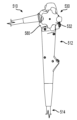
도 1a 내지 도 1c는 예시적인 의료 디바이스(10)의 다양한 도면을 예시한다. 도 1a는 의료 디바이스(10)의 정면도이고, 도 1b는 의료 디바이스(10)의 사시도이다. 도 1c는 의료 디바이스(10)의 근위 부분의 측면도이다. 의료 디바이스(10)는 손잡이 본체를 포함하는 손잡이(12), 및 손잡이(12)에서 원위 단부(16)까지 연장되는 디바이스 샤프트 또는 전달 샤프트(14)를 포함한다. 의료 디바이스(10)는 십이지장경, 내시경, 결장경, 요관경, 기관지경 등이나 또는 손잡이와 샤프트를 갖는 임의의 다른 유사한 의료 디바이스일 수 있다. 추가적으로, 의료 디바이스(10)는 제어 디바이스(30)를 포함한다. 제어 디바이스(30)는 손잡이(12)에 대해 이동 가능(예를 들어, 회전 가능)하고 전달 샤프트(14)의 일부(예를 들어, 원위 단부(16))의 움직임을 제어할 수 있다.1A-1C illustrate various views of an example
손잡이(12)는 예를 들어 손잡이(12)의 근위 부분에 하나 이상의 구멍(18A, 18B)을 포함할 수 있다. 구멍(18A, 18B) 중 하나 이상은 예를 들어 공기나 물의 전달을 제어하거나 손잡이(12)와 전달 샤프트(14)를 통한 흡입의 적용을 제어하기 위해 하나 이상의 밸브에 결합될 수 있거나 이를 수용할 수 있다.
추가적으로, 손잡이(12)는 전달 샤프트(14)의 하나 이상의 루멘과 연통하는, 예를 들어 원위 단부(16)까지 연장되는 하나 이상의 루멘(도시되지 않음)을 가질 수 있다. 이러한 양태에서, 손잡이(12)는 예를 들어 손잡이(12)의 중간 부분(예를 들어, 근위 부분과 원위 부분 사이)에 적어도 하나의 포트(20)를 포함할 수 있다. 포트(20)는 손잡이(12)의 하나 이상의 작업 채널 또는 루멘으로 개방될 수 있다. 포트(20)는 하나 이상의 도구 또는 엔드 이펙터를 수용할 수 있고, 하나 이상의 도구 또는 엔드 이펙터는 손잡이(12) 및 전달 샤프트(14)를 통해, 예를 들어 원위 단부(16) 밖으로 전달될 수 있다. 이러한 양태에서, 포트(20)는 하나 이상의 의료 디바이스(예를 들어, 겸자, 집게, 가위, 클립, 스테이플러, 바늘, 칼, 전극, 소작 루프, 등)를 수용하고, 하나 이상의 의료 디바이스를 전달 샤프트(14)의 원위 단부(16)에 근접한 영역으로 전달하도록 크기설정 및/또는 형상화될 수 있다. 추가적으로, 포트(20)는 예를 들어 밸브, 캡 상에 나사결합하는 나사부 등을 포함함으로써 의료 디바이스의 근위 부분 주위에 밀봉부를 형성하는 것을 돕도록 구성될 수 있다.Additionally, handle 12 may have one or more lumens (not shown) in communication with one or more lumens of
손잡이(12)는 도관(22)에 결합될 수 있다. 도관(22)은 손잡이(12)를 외부 전원, 처리 소프트웨어, 하나 이상의 디스플레이, 하나 이상의 메모리 또는 저장 디바이스 등에 연결할 수 있다. 이러한 양태에서, 의료 디바이스(10)는 원위 단부(16)에 하나 이상의 조명 디바이스 및/또는 카메라를 포함할 수 있고, 이들은 의료 디바이스(10) 내의 하나 이상의 통신 배선(도시되지 않음)를 통해 그리고 도관(22)을 통해 급전 및/또는 처리 소프트웨어, 하나 이상의 디스플레이, 메모리 등에 연결될 수 있다. 추가적으로, 도관(22)은 손잡이(12)를 하나 이상의 유체원, 예를 들어 공기원, 수원 등에 연결할 수 있다. 도관(22)은 또한 손잡이(12)를 흡입원에 연결할 수 있다. 이러한 양태에서, 구멍(18A, 18B)에 결합되거나 그 내부에 수용된 하나 이상의 밸브는 의료 디바이스(10)를 통한 전달 샤프트(14)의 원위 단부(16)에 근접한 영역으로의 공기 또는 물의 전달 및/또는 흡입 적용을 제어할 수 있다.
제어 디바이스(30)는 예를 들어 손잡이(12)의 근위 부분에서 손잡이(12)에 결합된다. 언급한 바와 같이, 제어 디바이스(30)는 손잡이(12)에 대해 이동 가능(예를 들어, 회전 가능)하고, 전달 샤프트(14)의 원위 단부(16)의 움직임(예를 들어, 편향)을 제어할 수 있다. 대안적으로, 제어 디바이스(30)는 전달 샤프트(14)의 승강기를 작동 또는 이동시킬 수 있거나, 달리, 의료 디바이스(10)의 케이블 구동 기능을 작동시킬 수 있다.The
제어 디바이스(30)는 다이얼, 휠, 레버, 노브(32), 또는 전달 샤프트(14)의 원위 단부(16)를 제1 방향 또는 제2 방향으로 편향시키도록 회전 가능할 수 있는 다른 회전 제어 요소를 포함할 수 있다. 도 1c에 도시된 바와 같이, 노브(32)는 손잡이(12)로부터 이격방향으로 (예를 들어, 손잡이(12)의 측면도에서 수직으로) 연장될 수 있다. 더욱이, 아래에 상세히 설명되는 바와 같이, 제어 디바이스(30)는 예를 들어 노브(32)의 위치를 로킹 및/또는 로킹 해제하는 것을 돕고, 따라서, 전달 샤프트(14)의 원위 단부(16)의 위치 또는 전달 샤프트(14)의 다른 양태를 로킹 및/또는 로킹 해제하는 것을 돕기 위해 하나 이상의 클러치 디바이스를 포함할 수 있다.
더욱이, 전달 샤프트(14)의 원위 단부(16)는 적어도 하나의 원위 개구(24)를 포함할 수 있고, 예를 들어, 이를 통해 의료 디바이스가 통해 연장될 수 있고, 유체가 전달될 수 있고, 흡입이 인가될 수 있거나, 또는, 의료 디바이스(10)가 달리 치료 부위를 치료할 수 있다. 도시되지는 않았지만, 원위 단부(16)는 또한 조명(예를 들어, LED) 및 이미징(예를 들어, 카메라)을 위한 하나 이상의 장치, 원위 개구(24)에서 나가는 기구 또는 의료 디바이스를 유도하는 승강기, 및/또는 관주 및/또는 흡입을 위한 개구를 포함할 수 있다. 더욱이, 의료 디바이스(10)는 원위 단부(16) 및/또는 의료 디바이스(10)의 다른 부분에서 다양한 기능을 제어하기 위한 하나 이상의 추가 컴포넌트(예를 들어, 프로세서, 메모리 등)를 포함할 수 있다.Moreover, the
도 2a 내지 도 2c는 제어 디바이스(30)의 다양한 도면을 예시한다. 도 2a는 제어 디바이스(30)의 정면도이다. 도 2b는 예를 들어 도 2a의 단면 2B-2B를 따른 제어 디바이스(30)의 단면도이다. 도 2c는 제어 디바이스(30)가 손잡이(12)에 결합될 때 예를 들어 손잡이(12)(도시되지 않음) 내부 위치로부터의 제어 디바이스(30)의 후면도이다. 언급한 바와 같이, 제어 디바이스(30)는 노브(32)를 포함한다. 노브(32)는 예를 들어 각각 노브(32)의 회전 중심(38)으로부터 반경방향 이격방향으로 연장되고 회전 중심을 향하여 반경방향으로 연장되는 하나 이상의 돌출부(34) 및 오목부(36)를 포함할 수 있다. 돌출부(34) 및 오목부(36)는 사용자가 노브(32)를 파지 및/또는 회전시키는 것을 도울 수 있다. 추가적으로, 노브(32)는 하나 이상의 표시, 예를 들어 우측 편향 표시(40A) 및 좌측 편향 표시(40B)를 포함할 수 있다. 이러한 양태에서, 우측 편향 표시(40A) 방향(예를 들어, 시계 방향)으로의 노브(32)의 회전은 전달 샤프트(14)의 원위 단부(16)를 우측으로 편향시킬 수 있고, 좌측 편향 표시(40B) 방향(예를 들어, 반시계 방향)으로의 노브(32)의 회전은 전달 샤프트(14)의 원위 단부(16)를 좌측으로 편향시킬 수 있다. 대안적으로, 다른 실시예에서, 노브(32)를 한 방향으로 회전시키면 승강기가 상승할 수 있고, 노브(32)를 또 다른 방향으로 회전시키면 승강기가 하강할 수 있다.2A-2C illustrate various views of
도 2a 내지 도 2c에 도시된 바와 같이, 제어 디바이스(30)는 하나 이상의 조향 또는 제어 요소(예를 들어, 링키지, 체인, 벨트, 와이어 등), 예를 들어 제1 제어 와이어(42A) 및 제2 제어 와이어(42B)를 포함한다. 적어도 하나의 양태에서, 제1 및 제2 제어 와이어(42A, 42B)는 노브(32)로부터 손잡이(12) 및 전달 샤프트(14)를 통해 전달 샤프트(14)의 원위 부분(예를 들어, 원위 단부(16))까지 연장될 수 있다. 다른 양태에서, 제1 및 제2 제어 와이어(42A, 42B)는 손잡이(12)를 통해 연장될 수 있고 하나 이상의 편향 와이어 또는 전달 샤프트(14)의 다른 제어 요소에 결합될 수 있다. 이러한 양태 중 임의의 양태에서, 노브(32)의 회전은 제어 와이어(42A, 42B)의 움직임을 제어하고, 따라서 노브(32)의 회전은 전달 샤프트(14)의 원위 단부(16)의 편향, 승강기의 작동을 제어하거나, 달리 의료 디바이스(10)의 케이블 구동 기능을 작동시킬 수 있다.2A-2C, the
도 2b에 도시된 바와 같이, 제어 디바이스(30)는 제어 샤프트(44)를 포함한다. 샤프트(44)는 노브(32)와 일체로 형성되거나 달리 노브에 고정식으로 결합될 수 있다. 샤프트(44)는 손잡이(12)의 근위 부분 내부로 연장될 수 있다. 제1 제어 와이어(42A)와 제2 제어 와이어(42B)의 근위 부분은 샤프트(44)에 간접적으로 결합될 수 있으며, 예를 들어, 샤프트(44)에 회전 가능하게 결합될 수 있는 요소(예를 들어, 스풀(50), 도 2b, 도 2c 및 도 3) 주위를 밀접하게 감싸서 고정할 수 있다. 예를 들어, 도 2c 및 도 3에 도시된 바와 같이, 스풀(50)은 제1 제어 와이어(42A)와 제2 제어 와이어(42B) 중 하나 이상의 근위 부분을 수용하여 제어 와이어(들)을 스풀(50)에 고정하기 위한 결합 부분(51)(예를 들어, 슬롯, 간극, 개구 등)을 포함할 수 있다. 와이어(42B)가 단면 2B-2B(도 1) 외부에 있기 때문에 와이어(42B)는 도 2b에 도시되지 않는다는 점에 유의한다. 그럼에도 불구하고, 둘 모두의 제어 와이어(42A, 42B)는 스풀(50)의 회전이 둘 모두의 제어 와이어(42A, 42B)의 움직임을 제어할 수 있도록 스풀(50)에 결합될 수 있다. 이러한 양태에서, 노브(32)의 회전은 스풀(50)을 회전시키는 샤프트(44)를 회전시키고, 이는 차례로 제1 및 제2 제어 와이어(42A, 42B) 중 하나를 근위 방향으로 당겨 전달 샤프트(14)의 원위 부분을 특정 방향으로 편향시킬 수 있다. 대안적으로, 노브(32)의 회전은 샤프트(44)를 회전시키고, 이는 차례로 스풀(50)을 통해 제1 및 제2 제어 와이어(42A, 42B) 중 하나를 근위 방향으로 당겨 전달 샤프트(14)의 승강기를 작동 또는 이동시킬 수 있거나 달리, 의료 디바이스(10)의 케이블 구동 기능을 작동시킬 수 있다. 더욱이, 도시되지는 않았지만 제어 디바이스(30)는 하나 이상의 기어, 스프로켓, 풀리, 크랭크 등을 포함할 수 있다. 제어 디바이스(30)는 또한 하나 이상의 랙, 체인, 벨트, 링키지 등을 포함할 수 있다.As shown in FIG. 2B ,
더욱이, 도 2b 및 도 2c에 도시된 바와 같이, 제어 디바이스(30)는 적어도 하나의 편향 디바이스, 예를 들어 적어도 하나의 스프링 클러치(46)를 포함한다. 스프링 클러치(46)는 적어도 부분적으로 원형일 수 있고 로드 또는 축(48)을 둘러싼다. 축(48)은 손잡이(12)에 대해 고정될 수 있다. 추가적으로, 도 2c에 도시된 바와 같이, 스프링 클러치(46)는 축(48) 주위, 예를 들어 축(48)과 스풀(50) 사이에 위치될 수 있다. 제어 디바이스(30)에 힘이 작용하지 않을 때, 스프링 클러치(46)는 축(48) 주위에 밀접하게 위치되거나 가압되어 축(48)에 대해, 그리고, 따라서, 손잡이(12) 및 전달 샤프트(14)에 대해, 스풀(50), 그리고, 따라서, 제1 및 제2 제어 와이어(42A, 42B)를 고정하는 것을 돕는다. 하나 이상의 양태에서, 스프링 클러치(46)는 예를 들어 스프링 클러치(46)와 축(48) 사이의 마찰 연결을 통해, 축(48)의 움직임, 그리고, 따라서, 제1 및 제2 제어 와이어(42A, 42B)의 움직임을 로킹, 유지 또는 달리 구속하는 것을 도울 수 있다.Moreover, as shown in FIGS. 2b and 2c , the
스프링 클러치(46)는 하나 이상의 다리(52)를 포함할 수 있다. 노브(32)와 샤프트(44)의 회전은 스프링 클러치(46)의 하나 이상의 다리(52)와 상호작용할 수 있다. 예를 들어, 노브(32)와 샤프트(44)의 회전은 샤프트(44)의 일부가 하나 이상의 다리(52)와 접촉하게 하여 스프링 클러치(46)를 풀림, 확장 또는 느슨해지게 하는 방향으로 하나 이상의 다리(52)를 밀 수 있다. 스프링 클러치(46)를 느슨해지게 하면, 스풀(50)과 축(48) 사이의 마찰 연결이 감소할 수 있다. 더욱이, 노브(32)와 샤프트(44)의 회전은 또한 샤프트(44)의 일부 또는 하나 이상의 다리(52)의 일부가 스풀(50)의 일부와 접촉시킬 수 있으며, 이는 스풀(50)이 회전하게 할 수 있다. 스풀(50)의 회전은 그 후 전달 샤프트(14)의 일부를 제어하기 위해, 예를 들어 원위 단부(16)를 편향시키기 위해, 제어 와이어(42A, 42B) 중 하나 이상을 근위 방향으로 후퇴시킬 수 있다.
아래에 상세히 설명되는 것처럼, 노브(32)에 힘이 더 이상 작용하지 않을 때, 스프링 클러치(46)가 수축하여 스풀(50)을 샤프트(48)에 대해 고정하는 것을 돕는다. 스풀(50)이 회전할 때 스프링 클러치(46)가 느슨해진 위치에 있기 때문에, 스프링 클러치(46)는 회전 전의 원래 위치를 향해 스풀(50)을 다시 압박하기 위한 탄성 복귀력을 제공하지 않는다. 따라서, 스프링 클러치(46)는 스풀(50)을 회전 위치에 로킹하는 것을 돕는다. 이러한 양태에서, 스프링 클러치(46)는 스풀(50), 그리고, 따라서 제1 및 제2 제어 와이어(42A, 42B)를 노브(32)에 작용하는 사용자가 선택한 위치에 고정하는 것을 돕는다. 예를 들어, 스풀(50)을 선택된 위치에 고정하는 것은 원위 단부(16)를 편향 또는 관절작동 위치에 고정하는 것을 도울 수 있다. 이러한 양태에서, 스풀(50)을 선택된 위치에 고정하는 것은 예를 들어 전달 샤프트(14)의 다른 부분에 대해 및/또는 치료 부위에 대해 선택된 구성(예를 들어, 조작된 위치)에서 원위 단부(16)를 로킹하거나 달리 유지하는 것을 도울 수 있다. 아래에 설명된 바와 같이, 제1 또는 제2 제어 와이어(42A 또는 42B)가 원위방향으로 당겨지는 경우(예를 들어, 굴곡되거나 편향되는 전달 샤프트(14) 부분으로부터의 고유 힘에 의해, 조직 또는 다른 물질과 접촉하는 전달 샤프트(14) 부분에 의해, 등), 제1 또는 제2 제어 와이어(42A 또는 42B)는 따라서 스풀(50)에 힘(들)을 부여할 수 있다. 힘(들)은 스풀(50)이 스프링 클러치(46)의 하나 이상의 다리(52)와 상호작용하게 할 수 있고, 스프링 클러치(46)가 조여지게 할 수 있으며, 따라서, 스풀(50)을 축(48)에 더욱 확실하게 고정하여 상대 회전을 방지하는 것을 돕는다.As will be explained in detail below, when there is no longer force acting on the
도 3은 노브(32), 샤프트(44), 적어도 하나의 스프링 클러치(즉, 2개의 스프링 클러치(46A 및 46B)), 축(48) 및 스풀(50)을 포함하는 제어 디바이스(30)의 분해도이다. 도시되지는 않았지만, 제어 와이어(42A, 42B)가 스풀(50)에 결합될 수 있다. 이러한 양태에서, 노브(32) 및 샤프트(44)의 회전은 스풀(50)을 회전시키고, 이는 전달 샤프트(도시되지 않음)의 원위 부분을 편향시키거나 달리 제어하도록 제어 와이어(42A, 42B)(도 2a 내지 도 2c)의 움직임을 제어할 수 있다.3 shows a
도시된 바와 같이, 손잡이(12) 내부의 샤프트(44)의 부분은 적어도 하나의 돌출부를 포함한다. 도 3에 도시된 바와 같이, 샤프트(44)는 예를 들어 2개의 돌출부(54A, 54B)를 포함할 수 있으며, 각각의 돌출부(54A, 54B)는 샤프트(44)의 양 측면, 예를 들어 샤프트(44)의 종방향 축선에 대한 양 측면에 있다. 샤프트(44)는 예를 들어 샤프트(44)의 종방향 부분으로부터(예를 들어, 노브(32) 반대쪽 샤프트(44)의 단부에서) 반경방향 외향 연장되는 반경방향 연장부(56)를 또한 포함할 수 있다. 이러한 양태에서, 돌출부(54A, 54B)는 반경방향 연장부(56)로부터 종방향으로 연장될 수 있다. 추가적으로, 스프링 클러치(46A, 46B)는 각각 개구(58A, 58B)를 갖는 와이어 코일로 형성되며, 각각은 예를 들어 적어도 부분적으로 원통형인 스프링 클러치(46A, 46B)로부터 각각 반경방향으로 이격방향으로 돌출하는 2개의 다리(52A, 52B, 52C, 52D)를 포함한다. 이러한 양태에서, 스프링 클러치(46A)는 2개의 다리(52A, 52B)를 포함하고, 스프링 클러치(46B)는 2개의 다리(52C, 52D)를 포함한다.As shown, the portion of
스풀(50)은 대체로 원통형인 외부 부분(58)을 포함할 수 있다. 더욱이, 스풀(50)은 예를 들어 축(48)을 수용하기 위한 대체로 원통형의 내부 개구(60)를 포함할 수 있고, 내부 개구(60)는 2개의 확장된 부분 또는 간극(62A, 62B)을 포함할 수 있다. 예를 들어, 간극(62A)은 간극(62A)의 양 단부 상에 제1 정지면(64A) 및 제2 정지면(64B)을 포함할 수 있다. 이러한 양태에서, 그리고, 아래에 설명된 바와 같이, 노브(32)와 샤프트(44)가 회전할 때, 돌출부(54A, 54B)는 다리(52A-52D) 및 간극(62A, 62B)과 상호작용할 수 있다. 더욱이, 도시되지는 않았지만, 제어 디바이스(30)는 예를 들어 하나 이상의 스풀(50)과 축(48) 사이에 생성된 마찰력을 수정하기 위해 추가적인 스프링 클러치를 포함할 수 있다. 추가적으로, 제어 디바이스(30)는 추가적인 스프링 클러치의 다리를 수용하고 작동시키기 위해 샤프트(44)로부터의 추가적인 돌출부, 스풀(50)의 간극 등을 포함할 수 있다.
도 2b, 도 2c 및 도 3을 참조하면, 제어 디바이스(30)가 조립될 때, 축(48)은 손잡이(12)의 일부에 고정식으로 결합된다. 스프링 클러치(46A, 46B)와 스풀(50)은 축(48)의 일부 주위에 위치될 수 있다. 예를 들어, 축(48)은 확장된 부분(66)을 포함할 수 있다. 스프링 클러치(46A 및 46B)의 개구(58A 및 58B)는 확장된 부분(66) 위에 위치될 수 있으며, 예를 들어 확장된 부분(66)을 따라 측방향으로 이격될 수 있다. 스프링 클러치(46A, 46B)가 확장된 부분(66) 위에 위치될 때, 스프링 클러치(46A, 46B)는 확장된 부분(66) 주위에 밀접하게 위치될 수 있다. 예를 들어, 스프링 클러치(46A, 46B)는 확장된 부분(66) 주위에 위치되기 위해 느슨해질 수 있다(그러나, 예를 들어, 각각의 스프링 클러치(46A, 46B)의 다리(52A-52D) 중 하나 이상을 핀칭하거나 달리 서로를 향해 이동시킴). 스풀(50)은 스프링 클러치(46A, 46B) 위에 그리고 또한 축(48)의 확장된 부분(66) 주위에 위치될 수 있다.2B, 2C and 3, when the
그 다음, 샤프트(44)는 축(48) 위에 위치될 수 있다. 예를 들어, 도 2b에 도시된 바와 같이, 샤프트(44)는 축(48)을 수용하는 내부 루멘을 포함한다. 축(48)은 결합 부분(68)을 포함할 수 있고, 노브(32)는 예를 들어 샤프트(44)의 루멘에 연결되는 개구(70)를 포함할 수 있다. 이러한 양태에서, 결합 요소(예를 들어, 나사, 볼트 등)가 축(48)을 노브(32)에 결합시키고 또한 이들 사이의 상대 회전을 허용하기 위해 사용될 수 있다.
샤프트(44)가 축(48) 위에 위치할 때, 반경방향 연장부(56)는 축(48)의 확장된 부분(66)에 접하거나 인접할 수 있다. 더욱이, 돌출부(54A, 54B)는 스프링 클러치(46A, 46B)의 다리(52A-52D) 쌍 사이에, 그리고, 간극(62A, 62B) 내에 위치될 수 있다. 예를 들어, 돌출부(54A)는 스프링 클러치(46A)의 다리(52B)와 스프링 클러치(46B)의 다리(52D) 사이에 그리고 또한 간극(62A) 내에 위치될 수 있다. 추가적으로, 돌출부(54B)는 스프링 클러치(46A)의 다리(54A)와 스프링 클러치(46B)의 다리(52C) 사이에 그리고 또한 간극(62B) 내에 위치될 수 있다.When
제어 디바이스(30)가 조립될 때, 노브(32), 그리고, 따라서, 샤프트(44)를 제1 방향, 예를 들어 시계 방향으로 회전시키는 것은 돌출부(54A)가 스프링 클러치(46A)의 다리(52B)와 접촉하고 다리(52B)를 시계 방향으로 밀게 할 수 있다. 이러한 접촉은 또한 스프링 클러치(46A) 전체를 회전시킬 수 있으며, 예를 들어 스프링 클러치(46A)의 다리(52B)를 간극(62A)의 정지면(64B)과 인접 접촉하게 할 수 있다. 노브(32)의 추가 회전은 스프링 클러치(46A)를 느슨하게 하여 스풀(50)이 스프링 클러치(46A)에 의해 축(48)에 대해 회전적으로 고정되지 않도록 할 수 있다. 추가적으로, 노브(32)와 샤프트(44)를 제1 방향으로 회전시키는 것은 또한 돌출부(54B)가 스프링 클러치(46B)의 다리(52C)와 접촉하고 다리(52C)를 시계 방향으로 밀게 할 수 있다. 이러한 접촉은 또한 스프링 클러치(46B) 전체를 회전시킬 수 있으며, 예를 들어 스프링 클러치(46B)의 다리(52C)를 간극(62B)의 정지면과 인접 접촉하게 할 수 있다. 노브(32)의 추가 회전은 스프링 클러치(46B)를 느슨하게 하여 스풀(50)이 스프링 클러치(46B)에 의해 축(48)에 대해 회전적으로 고정되지 않도록 할 수 있다.When the
반대로, 노브(32), 그리고, 따라서, 샤프트(44)를 제2 방향, 예를 들어 반시계 방향으로 회전시키는 것은 돌출부(54A)가 스프링 클러치(46B)의 다리(52D)와 접촉하고 다리(52D)를 반시계 방향으로 밀게 할 수 있다. 이러한 접촉은 또한 스프링 클러치(46B) 전체를 회전시킬 수 있으며, 예를 들어 스프링 클러치(46D)의 다리(52D)를 간극(62A)의 정지면(64A)과 인접 접촉하게 할 수 있다. 노브(32)의 추가 회전은 스프링 클러치(46B)를 느슨하게 하여 스풀(50)이 스프링 클러치(46B)에 의해 축(48)에 대해 회전적으로 고정되지 않도록 할 수 있다. 추가적으로, 노브(32)와 샤프트(44)를 제2 방향으로 회전시키는 것은 또한 돌출부(54B)가 스프링 클러치(46A)의 다리(52A)와 접촉하고 다리(52A)를 반시계 방향으로 밀게 할 수 있다. 이러한 접촉은 또한 스프링 클러치(46A) 전체를 회전시킬 수 있으며, 예를 들어 스프링 클러치(46A)의 다리(52A)를 간극(62B)의 정지면과 인접 접촉하게 할 수 있다. 노브(32)의 추가 회전은 스프링 클러치(46A)를 느슨하게 하여 스풀(50)이 스프링 클러치(46A)에 의해 축(48)에 대해 회전적으로 고정되지 않도록 할 수 있다.Conversely, rotating the
스프링 클러치(46A, 46B) 둘 모두가 느슨해진 상태에서, 노브(32)와 샤프트(44)의 회전은 스풀(50)을 회전시킬 수 있고, 따라서, 제1 제어 와이어(42A) 및/또는 제2 제어 와이어(42B)(도 2a 내지 도 2c) 중 적어도 하나의 움직임을 제어할 수 있다. 추가적으로, 앞서 설명한 바와 같이, 외력, 예를 들어 제어 와이어에 의해 스풀(50)에 부여된 힘은 하나 이상의 클러치 스프링(46A, 46B)을 조이는 방식으로 하나 이상의 클러치 스프링(46A, 46B)과 접촉하도록 스풀(50)을 회전시킬 수 있다. 예를 들어, 제어 와이어 중 하나로부터의 힘이 스풀(50)에 작용하여 스풀(50)을 시계 방향으로 회전시키면, 이때, 정지면(64A)은 다리(52D)와 접촉하고 다리(52D)를 시계 방향으로 밀 수 있으며, 이는 스프링 클러치(48B)를 조인다. 마찬가지로, 스풀(50)에 작용하는 시계 방향의 힘은 또한 간극(62B)의 정지면이 다리(52A)와 접촉하고 다리(52A)를 시계 방향으로 밀어 스프링 클러치(48A)를 조이게 할 수 있다. 이와 같이, 제어 디바이스(30)는 또한 전달 샤프트(14)의 일부를 조작된 위치에 유지하는 데 도움을 줄 수 있다.With both
도 4a 내지 도 4d는 예를 들어 노브(32)와 샤프트(44)의 회전에 기초하여 축(48)으로부터 스풀(50)을 선택적으로 회전적으로 결합 및 분리하는 제어 디바이스(30)에 통합될 수 있는 다양한 스프링 클러치를 예시한다. 도 4a에 도시된 바와 같이, 스프링 클러치(146)는 권선된 와이어의 코일(168)을 포함한다. 추가적으로, 앞서 설명한 바와 같이, 스프링 클러치(146)는 코일(168)로부터 이격방향으로 반경방향으로 연장되는 2개의 다리(152A, 152B)를 포함한다. 다리(152A, 152B)는 굴곡된 부분(170A, 170B)에 의해 코일(168)에 연결될 수 있다. 도시된 바와 같이, 코일(168)은 약 3개의 와이어 루프를 포함할 수 있다. 그러나, 비록 도시되지는 않았지만, 코일(168)은 더 적거나 더 많은 와이어 루프를 포함할 수 있으며, 이는 스프링 클러치(146)를 압축하는 데 필요한 힘의 양에 영향을 미칠 수 있고, 또한 축에 대해 스풀을 유지하는 스프링 클러치(146)에 의해 인가되는 유지력에도 영향을 미칠 수 있다. 앞서 설명한 바와 같이, 샤프트로부터의 돌출부는 스프링 클러치(146)를 느슨하게 하도록 다리(152A, 152B)와 상호작용할 수 있다.4A-4D may be incorporated into a
도 4b는 또 다른 예시적인 스프링 클러치(246)를 예시한다. 도시된 바와 같이, 스프링 클러치(246)는 예를 들어 적어도 부분적으로 원통형인 부분(272A) 및 상호작용 부분(272B)을 포함하는 링형 형상을 포함할 수 있다. 상호작용 부분(272B)은 예를 들어 스프링 클러치(246)의 원주의 일부를 따라 적어도 부분적으로 중첩되는 제1 단부(274A) 및 제2 단부(274B)를 포함한다. 제1 단부(274A)는 반경방향 외향 연장되는 다리(252A)를 포함할 수 있다. 제2 단부(274B)는 2개의 다리(252C, 252D)를 포함할 수 있고, 이들은 제1 단부(274A)를 이동 가능하게 수용하는 개구를 형성하도록 이격되어 있다. 이와 같이, 제1 단부(274A)와 제2 단부(274B)는 서로에 대해 이동 가능하다. 예를 들어, 다리(252A)와 원통형 부분(272A)의 일 단부 사이에 간격(276A)이 있을 수 있다. 추가적으로, 다리(252B, 252C)와 원통형 부분(272A)의 다른 단부 사이에 간격(276B, 276C)이 있을 수 있다. 이러한 양태에서, 다리(252A)는 간격(276A) 내에서 이동할 수 있다. 더욱이, 다리(252B, 252C)는 간격(276B, 276C) 내에서 이동할 수 있다. 앞서 설명한 바와 같이, 샤프트로부터의 돌출부는 다리(252A, 252B 또는 252C) 중 하나 이상과 상호작용하여 스프링 클러치(246)를 느슨하게 할 수 있다. 스프링 클러치(246)는 시트 금속으로 형성될 수 있다. 대안적으로, 스프링 클러치(246)는 예를 들어 사출 성형 공정을 통해 플라스틱 재료로 형성될 수 있다.4B illustrates another
도 4c는 또 다른 예시적인 스프링 클러치(346)를 예시한다. 도시된 바와 같이, 스프링 클러치(346)는 예를 들어 적어도 부분적으로 원통형인 부분(372A) 및 개방 부분(372B)을 포함하는 부분적인 링형 형상을 포함할 수 있다. 개방 부분(372B)은 제1 다리(352A)와 제2 다리(352B) 사이에서 연장될 수 있다. 앞서 설명한 바와 같이, 샤프트로부터의 돌출부는 다리(352A 또는 352B) 중 하나 이상과 상호작용하여 스프링 클러치(346)를 느슨하게 할 수 있다. 스프링 클러치(246)와 마찬가지로, 스프링 클러치(346)는 시트 금속으로 형성될 수 있거나, 대안적으로, 스프링 클러치(346)는 예를 들어 사출 성형 공정을 통해 플라스틱 재료로 형성될 수 있다.Figure 4C illustrates another
도 4d는 추가적인 예시적인 스프링 클러치(446)를 예시한다. 도시된 바와 같이, 스프링(446)은 또한 권선된 와이어의 코일(468)로 형성될 수 있다. 스프링 클러치(446)는 또한 코일(468)로부터 반경방향 내향 연장하는 2개의 다리(452A, 452B)를 포함한다. 다리(452A, 452B)는 굴곡된 부분(470A, 470B)에 의해 코일(468)에 연결될 수 있다. 이러한 양태에서, 도시되지는 않았지만, 손잡이의 하우징(축(48)과 유사)에 고정된 외부 실린더와 외부 실린더의 개구 내에 위치된 스풀을 포함하는 제어 디바이스를 위해 스프링(446)이 사용될 수 있다. 노브와 샤프트의 회전은 다리(452A, 452B)와 상호작용하여 스프링(346)을 선택적으로 느슨하게 하고, 내부 스풀을 회전시킬 수 있다. 더욱이, 스프링 클러치(46, 46A, 46B, 146, 246, 346) 중 하나 이상은 반경방향 내향 연장되는 각각의 다리를 포함하도록 수정될 수 있다.4D illustrates an additional
이러한 양태에서, 스프링 클러치(46, 46A, 46B, 146, 246, 346, 446) 중 하나 이상이 제어 디바이스(30)에 통합될 수 있다. 예를 들어, 제어 디바이스(30)용 스프링 클러치 중 하나를 선택할 때 원하는 스프링 압축력, 생산 비용 및 기타 요인을 고려할 수 있다. 추가적으로, 제어 디바이스(30)의 압축력은 스풀(50)을 축(48)에 결합하는 조립체에 하나 이상의 스프링 클러치를 추가 또는 제거(또는 예를 들어 코일의 루프를 추가하는 것에 의해 하나 이상의 스프링 클러치를 수정)하는 것에 의해 수정될 수 있다. 더욱이, 제어 디바이스(30)의 압축력은 스프링 클러치(들) 내에 위치하는 축(48)의 직경을 수정함으로써 수정될 수 있다. 제어 디바이스(30)의 압축력은 또한 제어 디바이스(30)의 재료 및/또는 마찰 특성을 수정함으로써 수정될 수 있다. 예를 들어, 축(48)은 테플론 코팅 샤프트로 형성될 수 있다. 대안적으로 또는 추가적으로, 스프링 클러치는 테플론 코팅된 와이어 또는 테플론을 함유한 플라스틱으로 형성될 수 있다. 더욱이, 하나 이상의 양태에서, 하나 이상의 마찰 감소제(예를 들어, 그리스)가 제어 디바이스(30) 내의 하나 이상의 표면에 추가될 수 있다.In this aspect, one or more of
추가적으로, 아래에 설명된 바와 같이, 예를 들어 노브 및 중공 튜브 또는 샤프트가 포개어진 상태로 2개보다 많은 제어 디바이스(30)가 사용될 수 있다. 더욱이, 각각의 스풀(50)에 2개의 제어 와이어(42A, 42B)가 결합되는 것으로 도시되어 있지만, 본 개시는 이에 제한되지 않는다. 예를 들어, 각각의 스풀(50)에 하나의 제어 와이어가 결합될 수 있거나, 또는 예를 들어 전달 샤프트(14)의 하나 이상의 부분에 추가적인 근위방향 수축력을 제공하기 위해 2개보다 많은 제어 와이어가 각각의 스풀(50)에 결합될 수 있다. 더욱이, 각각의 스풀(50)을 축(48)에 결합하는 2개의 스프링 클러치(46)가 도시되어 있지만, 본 개시는 이에 제한되지 않는다. 예를 들어, 각각의 스풀(50)에 하나의 스프링 클러치(46)가 사용될 수 있거나, 또는 예를 들어 스풀(50)을 축(48)에 선택적으로 결합하는 마찰력을 제어하기 위해 각각의 스풀(50)과 함께 2개보다 많은 스프링 클러치(46)가 사용될 수 있다. 스프링 클러치(46)의 수와 함께 스프링 클러치(46)의 크기, 재료, 강성, 탄성 등은 스풀(50)과 축(48) 사이의 마찰 결합을 제어하기 위해 원하는 바에 따라 수정될 수 있다.Additionally, as described below, more than two
도 5a 내지 도 5c는 본 개시에 따른 대안적인 예시적 의료 디바이스(510)의 다양한 도면을 예시한다. 도 5a 내지 도 5c는 참조 번호에 500을 추가하여 도시된 의료 디바이스(10)와 유사한 요소를 예시한다. 도 5a는 의료 디바이스(510)의 정면도이고, 도 5b는 의료 디바이스(510)의 사시도이다. 도 5c는 의료 디바이스(510)의 근위 부분의 측면도이다. 의료 디바이스(510)는 손잡이 본체를 포함하는 손잡이(512), 및 손잡이(512)에서 원위 단부(도시되지 않음)까지 연장되는 전달 샤프트(514)를 포함한다. 추가적으로, 의료 디바이스(510)는 제어 디바이스(530)를 포함한다.5A-5C illustrate various views of an alternative example
제어 디바이스(530)는 제1 노브(532)와 제2 노브(580)를 포함한다. 제2 노브(580)는 제1 노브(532)와 손잡이(512) 사이에 위치될 수 있다. 이러한 양태에서, 제1 노브(532)는 제1 양태에서 전달 샤프트(514)의 원위 부분을 작동 또는 제어하기 위해 손잡이(512)에 대해 회전 가능할 수 있고, 제2 노브(580)는 제2 양태에서 전달 샤프트(514)의 원위 부분을 작동 또는 제어하기 위해 손잡이(512)에 대해 회전 가능할 수 있다. 제1 노브(532), 제2 노브(580) 및 이들 각각의 연결은 실질적으로 동축일 수 있다. 일 양태에서, 제1 노브(532)는 전달 샤프트(514) 내의 제1 승강기를 제어할 수 있고, 제2 노브(580)는 전달 샤프트(514) 내의 제2 승강기를 제어할 수 있다. 다른 양태에서, 제1 노브(532)는 전달 샤프트(514)의 원위 단부를 제1 평면에서 편향시키도록 회전 가능할 수 있고, 제2 노브(580)는 전달 샤프트(514)의 원위 단부를 제2 평면에서 편향시키도록 회전 가능할 수 있다. 제2 평면은 제1 평면에 대략 수직일 수 있다. 이러한 양태에서, 제1 노브(532) 및 제2 노브(580)를 갖는 제어 디바이스(530)는 전달 샤프트(514)의 원위 단부로부터 연장되는 반구형 범위 내의 임의의 위치 또는 방향으로 원위 단부의 편향을 허용할 수 있다. 더욱이, 제1 노브(532)와 제2 노브(580)를 갖는 제어 디바이스(530)는 큰 편향각으로, 반구형 범위보다 더 큰 전달 샤프트(514)의 원위 단부로부터 연장되는 범위 내에서 임의의 위치 또는 방향으로 원위 단부의 편향을 허용할 수 있다. 또 다른 양태에서, 제1 노브(532)는 전달 샤프트(514)의 원위 단부의 편향을 제어할 수 있고, 제2 노브(580)는 승강기를 제어할 수 있거나, 또는, 그 반대도 가능하다. 이러한 양태에서, 제어 디바이스(530)는 내부 제동 디바이스를 포함하므로, 사용자가 손잡이(512) 외부로부터 작동 및/또는 해제할 수 있는 외부 제동 디바이스가 필요하지 않다.The
도 6a 및 도 6b는 제어 디바이스(530)의 도면을 예시한다. 도 6a는 예를 들어 도 2a의 단면 2B-2B와 유사한 단면을 따른 제어 디바이스(530)의 단면도이다. 도 6b는 제어 디바이스(530)가 손잡이(512)에 결합될 때 예를 들어 손잡이(512) 내부 위치(도 5a 내지 도 5c)로부터의 제어 디바이스(530)의 후면도이다. 제어 디바이스(530)는 앞서 설명한 바와 같이 전달 샤프트(514)의 하나 이상의 컴포넌트를 제어할 수 있는 2개 이상의 조향 또는 제어 와이어, 예를 들어 542A, 542B, 542C 및 542D를 포함한다.6A and 6B illustrate diagrams of
앞서 설명한 바와 같이, 노브(532)는 제어 샤프트(544)에 결합되거나 제어 샤프트와 일체로 형성될 수 있다. 샤프트(544)는 축(548)의 일부를 수용하기 위한 내부 루멘을 포함할 수 있고, 또한 하나 이상의 제어 와이어, 예를 들어 제1 제어 와이어(542A)의 움직임을 제어하기 위해 스풀(550)과 상호작용할 수 있다. 추가적으로, 하나 이상의 스프링 클러치(546A)는 스풀(550)과 축(548)의 일부 사이에 위치되어 스풀(550)을 축(548)에 선택적으로 회전적으로 고정하거나 로킹할 수 있다.As previously described,
추가적으로, 노브(580)는 제어 샤프트(582)에 결합되거나 일체로 형성될 수 있다. 샤프트(582)는 샤프트(544)의 일부를 수용하고, 따라서, 축(548)을 또한 수용하는 내부 루멘을 포함할 수 있다. 일 양태에서, 중공 축(578)은 샤프트(544)와 샤프트(582) 사이에 위치될 수 있다. 샤프트(582)는 또한 하나 이상의 제어 와이어, 예를 들어 제2 제어 와이어(542B)의 움직임을 제어하기 위해 스풀(584)과 상호작용할 수 있다. 추가적으로, 하나 이상의 스프링 클러치(546C)는 스풀(584)과 중공 축(578)의 일부 사이에 위치되어 스풀(584)을 중공 축(578)에 선택적으로 회전적으로 고정하거나 로킹할 수 있다. 더욱이, 중공 축(578)은 연장 부분(586)을 포함할 수 있다. 연장 부분(586)은 스풀(550)과 스풀(584) 사이에 위치될 수 있고, 스풀(550)과 스풀(584)이 서로 별도로 작동되고 회전될 수 있게 하는 것을 도울 수 있다.Additionally,
샤프트(544), 스프링 클러치(546A), 축(548) 및 스풀(550)은 도 2a 내지 도 2c 및 도 3의 대응 구조에 대해 설명된 바와 같이 축(548)에 대한 샤프트(544) 및 스풀(550)의 회전을 선택적으로 로킹하고 로킹 해제하도록 동작한다. 도 6b에 도시된 바와 같이, 스프링 클러치(546A)는 축(548) 주위, 예를 들어 축(548)과 스풀(550) 사이에 위치될 수 있다. 제어 디바이스(530)에 힘이 작용하지 않을 때, 스프링 클러치(546A)는 축(548) 주위에 밀접하게 위치되거나 가압되어 스풀(550)을 고정하는 것을 도우며, 따라서, 축(548)에 대해, 그리고, 따라서 손잡이(512) 및 전달 샤프트(514)에 대해 제1 제어 와이어(542A)를 고정하는 것을 돕는다. 스프링 클러치(546A)는 하나 이상의 다리(552)를 포함할 수 있다. 노브(532) 및 샤프트(544)의 회전은 스프링 클러치(546A)의 다리(552) 중 하나 이상과 상호작용할 수 있다. 예를 들어, 노브(532) 및 샤프트(544)의 회전은 샤프트(544)의 일부가 다리(552) 중 하나 이상과 접촉하게 하여 다리(552) 중 하나 이상을 스프링 클러치(546A)를 풀거나 느슨하게 하는 방향으로 밀 수 있다. 스프링 클러치(546A)를 느슨하게 하면 스풀(550)과 축(548) 사이의 마찰 연결이 감소될 수 있다. 더욱이, 회전 노브(532) 및 샤프트(544)는 또한 샤프트(544)의 일부 또는 하나 이상의 다리(552)의 일부가 스풀(550)의 일부와 접촉하게 할 수 있으며, 이는 스풀(550)이 회전하게 할 수 있다. 스풀(550)을 회전시키는 것은, 그 후, 전달 샤프트(514)의 일부를 제어하기 위해 제어 와이어(542A)를 근위 방향으로 후퇴시킬 수 있다.
마찬가지로, 도 6a 및 도 6b에 도시되지는 않았지만, 예를 들어 노브(580)를 회전시키는 것이 스프링 클러치(546C)를 느슨하게 하고, 따라서, 스풀(584)과 중공 축(578) 사이의 마찰 연결을 감소시키도록 샤프트(582)는 스프링 클러치(546C)의 하나 이상의 다리와 상호작용할 수 있다.Likewise, although not shown in FIGS. 6A and 6B , for example,
도 7은 노브(532), 샤프트(544), 적어도 하나의 스프링 클러치(즉, 2개의 스프링 클러치(546A, 546B)), 축(548) 및 스풀(550)을 포함하는 제어 디바이스(530)의 분해도이다. 도시되지는 않았지만, 하나 이상의 제어 와이어(예를 들어, 제어 와이어(542A 및 542B))가 스풀(550)에 결합될 수 있다. 이러한 양태에서, 노브(532) 및 샤프트(544)의 회전은 스풀(550)을 회전시키고, 이는 도 2a 내지 도 2c 및 도 3에 도시된 노브(32), 샤프트(44), 스프링 클러치(46), 축(48), 스풀(50) 및 제어 와이어(42A, 42B)의 상호작용과 유사하게 전달 샤프트(도시되지 않음)의 원위 부분을 편향시키거나 달리 제어하기 위해 하나 이상의 제어 와이어의 움직임을 제어할 수 있다. 앞서 설명한 바와 같이, 노브(530) 및 샤프트(544)의 회전은 스프링 클러치(546A 또는 546B) 중 하나 이상을 느슨하게 할 수 있다. 예를 들어, 샤프트(544)는 하나 이상의 돌출부, 예를 들어 반경방향 연장부(556)를 통해 샤프트(544)에 결합된 제1 및 제2 돌출부(554A, 554B)를 포함한다. 돌출부(554A, 554B)는 앞서 설명한 바와 같이 스프링 클러치(546A, 546B)의 다리와 상호작용하여 스프링 클러치(546A, 546B)를 느슨하게 하고 스풀(550)과 축(548)의 확장된 부분(566) 사이의 연결을 느슨하게 할 수 있다. 더욱이, 앞서 설명한 바와 같이, 다리는 하나 이상의 정지면(예를 들어, 정지면(564A 및 564B))과 상호작용하여 스풀(550)을 회전시켜 하나 이상의 제어 와이어(도시되지 않음)를 제어할 수 있다.7 shows a
추가적으로, 도 7에 도시된 바와 같이, 제어 디바이스(530)는 노브(580), 샤프트(582), 적어도 하나의 추가적인 스프링 클러치(즉, 2개의 스프링 클러치(546C, 546D)) 및 스풀(584)을 포함한다. 도시되지는 않았지만, 하나 이상의 제어 와이어(예를 들어, 제어 와이어(542C 및 542D))가 스풀(584)에 결합될 수 있다. 이 조립체는 도 2a 내지 도 2c 및 도 3에 도시된 노브(32), 샤프트(44), 스프링 클러치(46), 축(48), 스풀(50) 및 제어 와이어(42A, 42B)의 상호작용과 대부분 동일한 방식으로 동작한다. 구체적으로, 회전 노브(580)와 샤프트(582)는 앞서 설명한 바와 같이 스프링 클러치(546C, 546D)와 상호작용하여 느슨해지게 하고 스풀(584)을 회전시킬 수 있다. 스풀(584)의 회전은 전달 샤프트(도시되지 않음)의 원위 부분을 편향시키거나 달리 제어하기 위해 하나 이상의 제어 와이어의 움직임을 제어할 수 있다. 더욱이, 중공 축(578)은 손잡이(512)에 고정될 수 있고, 샤프트(544, 582)가 별도로 회전할 수 있게 하는 것을 도울 수 있다. 더욱이, 중공 축(578)은 스풀(550, 584)을 분리할 수 있고 스풀(550, 584)이 별도로 회전할 수 있게 하는 연장 부분(586)을 포함할 수 있다.Additionally, as shown in FIG. 7 , the
더욱이, 회전 노브(580)와 샤프트(582)는 스프링 클러치(546C 또는 546D) 중 하나 이상을 느슨하게 할 수 있다. 예를 들어, 샤프트(582)는 반경방향 연장부(590)를 통해 샤프트(582)에 결합된 하나 이상의 돌출부, 예를 들어 제1 및 제2 돌출부(588A, 588B)를 포함한다. 돌출부(588A, 588B)는 앞서 설명한 바와 같이 스프링 클러치(546C, 546D)의 다리와 상호작용하여 스프링 클러치(546C, 546D)를 느슨하게 하고 스풀(584)과 중공 축(578) 사이의 연결을 느슨하게 할 수 있다. 더욱이, 앞서 설명한 바와 같이, 다리는 하나 이상의 제어 와이어(도시되지 않음)를 제어하기 위해 스풀(584)을 회전시키기 위해 하나 이상의 정지면(예를 들어, 정지면(592A 또는 592B))과 상호작용할 수 있다.Moreover,
더욱이, 앞서 설명한 바와 같이, 외력, 예를 들어 제어 와이어에 의해 스풀(550) 또는 스풀(584)에 부여되는 힘은, 클러치 스프링(546A, 546B, 546C, 546D) 중 하나 이상을 조이는 방식으로, 클러치 스프링(546A, 546B, 546C, 546D) 중 하나 이상과 접촉하도록, 스풀(550) 또는 스풀(584)을 회전시킬 수 있다. 예를 들어, 제어 와이어는 전달 샤프트(514)가 굴곡되지 않은 위치 또는 편향되지 않은 위치로 복귀하도록 편향시키는 전달 샤프트(514)의 고유 힘, 치료 부위의 조직 또는 다른 물질과 접촉하는 전달 샤프트(514)의 원위 단부에 의해 야기되는 힘 등으로부터의 힘을 부여할 수 있지만, 이들 힘은 스풀(550, 584)이 하나 이상의 클러치 스프링(546A, 546B, 546C, 546D)과 접촉하여 조이게 할 수 있다. 이와 같이, 제어 디바이스(530)는 또한 전달 샤프트(514)의 일부를 조작된 위치에 유지하는 것을 도울 수 있다.Moreover, as previously described, an external force, for example, a force imparted to the
스프링 클러치 중 하나 이상 및 임의의 조합이 제어 디바이스(530)에 통합될 수 있다. 추가적으로, 예를 들어 전달 샤프트의 2개보다 많은 양태를 제어하기 위해 2개보다 많은 노브, 샤프트 등이 손잡이(512)에 포함될 수 있다. 예를 들어, 3개의 노브가 손잡이(512)의 제어 디바이스에 통합될 수 있다. 제1 및 제2 노브는 2개의 서로 다른 평면에서 전달 샤프트(514)를 편향시키도록 구성될 수 있고, 제3 노브는 예를 들어 도 1a 및 도 1b의 원위 개구(24)에 인접하여 위치된 승강기를 작동시키도록 구성될 수 있다.One or more and any combination of spring clutches may be integrated into
본 출원에 설명된 다양한 양태는 의료 절차의 기간, 비용 및/또는 위험을 감소시키는 데 도움이 될 수 있다. 예를 들어, 제어 디바이스는 사용자가 하나 이상의 제어 와이어를 선택적으로 조작할 수 있게 한다. 또한, 제어 디바이스는 제어 와이어를 선택한 위치에 로킹하고, 예를 들어 전달 샤프트에 작용하는 힘으로 인해 제어 와이어의 부주의한 움직임을 방지하는 것을 또한 돕는다. 이러한 양태에서, 제어 디바이스는 소수의 저렴한 컴포넌트로 브레이크를 제공하는 것을 도울 수 있다. 스프링 클러치(들)에 의해 부여되는 스프링 힘으로 인해, 사용자 조작에 의해 노브와 샤프트가 회전되면 제어 디바이스에 의해 제공되는 브레이크가 자동으로 분리되고, 사용자 조작이 끝난 후에 제어 디바이스에 의해 제공되는 브레이크가 자동으로 결합된다. 예를 들어, 사용자는 노브를 회전시켜 전달 샤프트의 원위 단부를 편향시킬 수 있다. 사용자는 회전된 위치에서 노브를 놓을 수 있으며, 하나 이상의 스프링 클러치는 자동으로 수축 위치로 복귀하여 스풀을 축에 고정할 수 있다. 이러한 양태에서, 제어 와이어로부터 스풀에 부여된 힘 또는 제어 와이어로부터의 배압은 하나 이상의 스프링 클러치를 조이게 하고 제어 와이어에 의해 부여된 힘이 스풀을 회전시키는 것을 방지하는 것을 돕는다.Various aspects described in this application may help reduce the duration, cost, and/or risk of medical procedures. For example, a control device allows a user to selectively manipulate one or more control wires. Additionally, the control device locks the control wire in a selected position and also helps prevent inadvertent movement of the control wire, for example due to forces acting on the transmission shaft. In this aspect, the control device can help provide braking with a few inexpensive components. Due to the spring force imparted by the spring clutch(s), the brake provided by the control device is automatically disengaged when the knob and shaft are rotated by user operation, and the brake provided by the control device is released after the user operation is completed. are automatically combined. For example, a user can rotate a knob to deflect the distal end of the delivery shaft. The user can release the knob in the rotated position and one or more spring clutches will automatically return to the retracted position to secure the spool to the shaft. In this aspect, the force imparted to the spool from the control wire or the back pressure from the control wire tightens one or more spring clutches and helps prevent the force imparted by the control wire from rotating the spool.
추가적으로, 하나 이상의 스프링 클러치는 일반적으로 이용 가능한 스프링 또는 와이어 재료로 형성될 수 있다. 대안적으로, 하나 이상의 스프링 클러치는 스탬핑된 시트 금속, 플라스틱 재료, 사출 성형 클립 등으로 형성될 수 있다. 하나 이상의 스프링 클러치의 크기, 수, 재료 등은 또한 특정 의료 디바이스 또는 의료 디바이스의 특정 응용에 맞춤화될 수 있다. 활주되기 전에 각각의 스프링 클러치가 견딜 수 있는 마찰량은 각각의 스프링 클러치의 특성에 따라 달라질 수 있다. 그러나, 각각의 스프링 클러치가 활주되기 전에 견딜 수 있는 마찰량은 또한 하나 이상의 스프링 클러치를 구성하는 랩(wrap) 또는 코일의 수(또는 종방향 폭), 와이어의 재료 특성, 하나 이상의 스프링 클러치의 내경과 축의 외경 사이의 간섭으로 인한 예부하 마찰(pre-loaded friction)의 양(예를 들어, 중립 또는 비작동 위치에서 스프링이 축에 얼마나 "밀접"하는지) 등에 따라 달라진다. 스풀에 제공되는 마찰력은 또한 축 주위에 포함된 스프링 클러치의 수에 따라 제어(예를 들어, 증가 또는 감소)될 수 있다. 이때, 마찰력은 전달 샤프트가 자연적으로 직선 또는 비작동 위치로 돌아가는 것을 방지하기에 충분한 동시에 또한 노브와 샤프트가 전달 샤프트의 일부를 작동시키기 위해 하나 이상의 스프링 클러치를 해제하고 스풀을 회전시키는 데 필요한 구동력을 최소화할 수 있는 유지력을 제공할 수 있다.Additionally, one or more spring clutches may be formed from commonly available spring or wire materials. Alternatively, the one or more spring clutches may be formed from stamped sheet metal, plastic material, injection molded clips, etc. The size, number, material, etc. of one or more spring clutches may also be customized to a particular medical device or specific application of a medical device. The amount of friction that each spring clutch can withstand before sliding may vary depending on the characteristics of each spring clutch. However, the amount of friction that each spring clutch can withstand before sliding also depends on the number (or longitudinal width) of wraps or coils that make up one or more spring clutches, the material properties of the wire, and the inner diameter of one or more spring clutches. It depends on the amount of pre-loaded friction due to interference between the spring and the outer diameter of the shaft (i.e. how "close" the spring is to the shaft in the neutral or non-actuated position). The friction force provided to the spool can also be controlled (eg increased or decreased) depending on the number of spring clutches included around the shaft. At this time, the friction force is sufficient to prevent the transmission shaft from naturally returning to its straight or non-actuated position, while also providing the drive force necessary for the knob and shaft to disengage one or more spring clutches and rotate the spool to operate a portion of the transmission shaft. It can provide minimal holding power.
제어 디바이스는 손잡이의 어느 곳에나, 예를 들어 의료 절차 중에 편리한 위치에 위치될 수 있다. 더욱이, 제어 디바이스는 외부 제동 시스템(손잡이 본체 외부의 제동 컴포넌트)을 필요로 하지 않으며, 이는 제어 디바이스 및 의료 디바이스의 전체 크기 감소 및 유용성에 도움이 될 수 있다. 또한, 외부 제동 시스템이 필요하지 않으므로, 제어 디바이스의 노브(들)를 손잡이에 인접하거나 근접하게 위치시킬 수 있게 하는 데 도움이 될 수 있으며, 이는 특히 손이 작은 사용자의 경우 의료 디바이스의 인체 공학 및/또는 유용성을 개선시킬 수 있다. 또한, 외부 제동 시스템이 필요하지 않으므로, 손잡이의 전체 크기가 감소될 수 있어서, 예를 들어 (예를 들어, 멸균 동안) 손잡이가 테이블에서 넘어지거나 및/또는 떨어질 수 있는 위험이 감소되고, 의료 디바이스를 포장하는 데 필요한 포장의 크기 및/또는 양이 감소되고, 의료 디바이스 등을 보관하는 데 필요한 공간이 감소한다.The control device can be positioned anywhere on the handle, for example in a convenient position during medical procedures. Moreover, the control device does not require an external braking system (braking components external to the handle body), which may aid in overall size reduction and usability of the control device and medical device. Additionally, since an external braking system is not required, it may be helpful to allow the knob(s) of the control device to be positioned adjacent to or close to the handle, which may be beneficial to the ergonomics of the medical device and /or may improve usability. Additionally, since an external braking system is not required, the overall size of the handle can be reduced, reducing the risk of the handle tipping over and/or falling off a table, for example (e.g. during sterilization), and allowing the handle to fall off the medical device. The size and/or amount of packaging required to package is reduced, and the space required to store medical devices, etc. is reduced.
언급한 바와 같이, 제어 디바이스는 제어 와이어를 자동으로 고정할 수 있으며, 따라서, 전달 샤프트의 제어 부분을 선택된 위치에 고정할 수 있다. 따라서, 사용자가 외부 브레이크 요소를 조작하거나 하나 이상의 컴포넌트를 한 위치에 달리 로킹한 다음 최종 또는 더 작은 조작을 위해 로킹 구성에서 컴포넌트를 조작할 필요가 없으며, 이러한 조작은 내부 컴포넌트에 응력을 부여하고, 사용자의 손 피로를 악화시키는 등의 문제가 있다. 더욱이, 앞서 설명한 바와 같이, 전달 샤프트의 원위 단부를 다수의 방향으로 편향시키고, 전달 샤프트에 있는 하나 이상의 승강기를 작동 또는 이동시키고/거나, 달리, 의료 디바이스의 케이블 구동 기능을 작동시키기 위해 다수의 제어 디바이스가 하나의 손잡이에 통합될 수 있다.As mentioned, the control device can automatically secure the control wire and thus the control part of the transmission shaft in the selected position. Thus, there is no need for the user to manipulate external break elements or otherwise lock one or more components in one position and then manipulate the components in a locking configuration for final or minor manipulations, which would otherwise impose stresses on the internal components. There are problems such as worsening the user's hand fatigue. Moreover, as previously described, a plurality of controls are provided to deflect the distal end of the delivery shaft in multiple directions, actuate or move one or more elevators on the delivery shaft, and/or otherwise operate the cable drive function of the medical device. The device can be integrated into one handle.
따라서, 본 출원에 설명된 다양한 양태는 치료 효능 및/또는 절차, 예를 들어 치료 부위를 치료하는 절차로부터의 회복을 개선하는 것을 도울 수 있다. 본 출원에 설명된 다양한 양태는 절차의 기간을 감소 및/또는 최소화하는 것을 도울 수 있고, 사용자에 의한 부주의한 조작의 위험을 감소시킬 수 있으며, 그리고/또는 전달, 재배치 또는 절차 중 의료 디바이스의 사용 동안 조직 또는 다른 물질과의 부주의한 접촉 위험을 감소시키는 것을 도울 수 있다.Accordingly, the various aspects described in this application can help improve treatment efficacy and/or recovery from a procedure, such as treating a treatment area. Various aspects described in this application may help reduce and/or minimize the duration of a procedure, reduce the risk of inadvertent manipulation by a user, and/or the delivery, repositioning, or use of a medical device during a procedure. It can help reduce the risk of inadvertent contact with tissue or other substances during treatment.
본 개시의 원리가 다양한 응용에 대한 예시적인 양태를 참조하여 본 출원에 설명되지만, 본 개시는 이에 제한되지 않는다는 것이 이해하여야 한다. 본 출원에 제공된 교시를 이용할 수 있는 본 기술 분야의 숙련자는 추가적인 수정, 응용, 양태 및 등가물의 대체가 모두 본 출원에 설명된 양태의 범위 내에 속한다는 것을 인식할 것이다. 따라서, 본 개시는 앞서 설명한 설명에 의해 제한되는 것으로 고려되어서는 안 된다.Although the principles of the disclosure are described in this application with reference to illustrative embodiments for various applications, it is to be understood that the disclosure is not limited thereto. Those skilled in the art who can utilize the teachings provided in this application will recognize that additional modifications, applications, aspects, and equivalent substitutions are all within the scope of the aspects described in this application. Accordingly, the present disclosure should not be considered limited by the foregoing description.
Claims (15)
축을 포함하는 손잡이;
손잡이에서 원위 단부까지 연장되는 디바이스 샤프트; 및
제어 디바이스를 포함하고, 제어 디바이스는 손잡이에 결합되고, 제어 디바이스는
손잡이에 대해 회전 가능한 노브;
노브로부터 연장되는 제어 샤프트;
2개의 다리를 포함하는 적어도 하나의 스프링 클러치;
축에 대해 회전 가능한 스풀; 및
스풀에 결합된 하나 이상의 와이어를 포함하고,
노브의 회전은 제어 샤프트를 회전시켜, 적어도 하나의 스프링 클러치가 느슨해지게 하고, 스풀이 회전하게 하고, 하나 이상의 와이어가 이동하게 하도록 구성되는, 의료 디바이스.It is a medical device,
a handle containing an axis;
a device shaft extending from the handle to the distal end; and
comprising a control device, the control device being coupled to the handle, the control device being
Knob rotatable relative to the handle;
a control shaft extending from the knob;
at least one spring clutch including two legs;
Spool rotatable about an axis; and
comprising one or more wires coupled to a spool,
Rotating the knob rotates the control shaft, causing the at least one spring clutch to loosen, the spool to rotate, and the one or more wires to move.
제1 방향으로 노브를 추가로 회전시키면 (1) 제1 스프링 클러치의 제1 다리가 제1 간극에 인접한 스풀의 제1 정지면과 접촉하고, (2) 제2 스프링 클러치의 제1 다리가 제2 간극에 인접한 스풀의 제2 정지면에 접촉하고, (3) 스풀이 제1 방향으로 회전하게 하는, 의료 디바이스.5. The method of claim 4, wherein rotation of the knob in the first direction causes the first protrusion to contact the first leg of the first spring clutch to loosen the first spring clutch, and rotation of the knob in the first direction causes the first protrusion to contact the first leg of the first spring clutch. 2 The protrusion contacts the first leg of the second spring clutch to loosen the second spring clutch,
Further rotation of the knob in the first direction causes (1) the first leg of the first spring clutch to contact the first stop surface of the spool adjacent the first gap, and (2) the first leg of the second spring clutch to contact the first stop surface of the spool adjacent to the first gap. 2 contacting a second stop surface of the spool adjacent the gap, and (3) causing the spool to rotate in a first direction.
제2 방향으로 노브를 추가로 회전시키면 (1) 제2 스프링 클러치의 제2 다리가 제2 간극에 인접한 스풀의 제3 정지면과 접촉하고, (2) 제1 스프링 클러치의 제2 다리가 제2 간극에 인접한 스풀의 제4 정지면에 접촉하고, (3) 스풀이 제2 방향으로 회전하게 하는, 의료 디바이스.6. The method of claim 4 or 5, wherein rotation of the knob in the second direction causes the first protrusion to contact the second leg of the second spring clutch, loosening the second spring clutch, and rotating the knob in the second direction causes the first protrusion to contact the second leg of the second spring clutch. Rotation of causes the second protrusion to contact the second leg of the first spring clutch, thereby loosening the first spring clutch,
Further rotation of the knob in the second direction causes (1) the second leg of the second spring clutch to contact the third stop surface of the spool adjacent the second gap, and (2) the second leg of the first spring clutch to contact the third stop surface of the spool adjacent to the second gap. 2 contacting a fourth stop surface of the spool adjacent the gap, and (3) causing the spool to rotate in a second direction.
손잡이에 대해 회전 가능한 제2 노브;
제2 노브로부터 연장되는 제2 제어 샤프트;
2개의 다리를 포함하는 적어도 하나의 제2 스프링 클러치;
축에 대해 회전 가능한 제2 스풀; 및
제2 스풀에 결합된 하나 이상의 제2 와이어를 포함하고,
제2 노브의 회전은 제2 제어 샤프트를 회전시켜 적어도 하나의 제2 스프링 클러치가 느슨해지고, 제2 스풀이 회전하고, 하나 이상의 제2 와이어가 이동하게 하도록 구성되는, 의료 디바이스.11. The method according to any one of claims 1 to 10, wherein the control device is a first control device and the medical device further comprises a second control device coaxial with the first control device, the second control device
a second knob rotatable relative to the handle;
a second control shaft extending from the second knob;
at least one second spring clutch including two legs;
a second spool rotatable about an axis; and
comprising at least one second wire coupled to the second spool,
Rotation of the second knob is configured to rotate the second control shaft to cause the at least one second spring clutch to loosen, the second spool to rotate, and the one or more second wires to move.
제어 샤프트의 일부를 제2 제어 샤프트로부터 분리하는 중공 축을 더 포함하고, 중공 축은 손잡이에 결합되고, 제1 제어 디바이스의 스풀을 제2 제어 디바이스의 제2 스풀로부터 분리하는 반경방향 연장부를 포함하는, 의료 디바이스.12. The method of claim 11, wherein a portion of the control shaft of the first control device is nested within the second control shaft of the second control device, and the medical device
further comprising a hollow shaft separating a portion of the control shaft from the second control shaft, the hollow shaft being coupled to the handle and comprising a radial extension separating the spool of the first control device from the second spool of the second control device, Medical devices.
Applications Claiming Priority (3)
| Application Number | Priority Date | Filing Date | Title |
|---|---|---|---|
| US202163190267P | 2021-05-19 | 2021-05-19 | |
| US63/190,267 | 2021-05-19 | ||
| PCT/US2022/072396 WO2022246417A1 (en) | 2021-05-19 | 2022-05-18 | Medical devices and related methods |
Publications (1)
| Publication Number | Publication Date |
|---|---|
| KR20240009456A true KR20240009456A (en) | 2024-01-22 |
Family
ID=82067706
Family Applications (1)
| Application Number | Title | Priority Date | Filing Date |
|---|---|---|---|
| KR1020237043273A KR20240009456A (en) | 2021-05-19 | 2022-05-18 | Medical devices and related methods |
Country Status (7)
| Country | Link |
|---|---|
| US (1) | US20220369901A1 (en) |
| EP (1) | EP4301204A1 (en) |
| KR (1) | KR20240009456A (en) |
| CN (1) | CN117396122A (en) |
| AU (1) | AU2022276027A1 (en) |
| CA (1) | CA3216658A1 (en) |
| WO (1) | WO2022246417A1 (en) |
Family Cites Families (5)
| Publication number | Priority date | Publication date | Assignee | Title |
|---|---|---|---|---|
| JP2940327B2 (en) * | 1993-01-28 | 1999-08-25 | 富士写真光機株式会社 | Angle lock release device for endoscope |
| US10648201B2 (en) * | 2015-10-26 | 2020-05-12 | Magna Closures S.P.A. | Inertial lock device for release cable assembly |
| US10788082B2 (en) * | 2018-05-21 | 2020-09-29 | Eaton Intelligent Power Limited | Transmission clutch including locking torsion spring |
| CN116490113A (en) * | 2020-09-30 | 2023-07-25 | 波士顿科学国际有限公司 | Medical device with adjustable rigidity |
| CN112438686A (en) * | 2020-12-08 | 2021-03-05 | 江苏唯德康医疗科技有限公司 | Endoscope handle structure with locking function and endoscope thereof |
-
2022
- 2022-05-18 WO PCT/US2022/072396 patent/WO2022246417A1/en active Application Filing
- 2022-05-18 CA CA3216658A patent/CA3216658A1/en active Pending
- 2022-05-18 US US17/663,933 patent/US20220369901A1/en active Pending
- 2022-05-18 KR KR1020237043273A patent/KR20240009456A/en unknown
- 2022-05-18 CN CN202280036128.6A patent/CN117396122A/en active Pending
- 2022-05-18 AU AU2022276027A patent/AU2022276027A1/en active Pending
- 2022-05-18 EP EP22731033.1A patent/EP4301204A1/en active Pending
Also Published As
| Publication number | Publication date |
|---|---|
| CN117396122A (en) | 2024-01-12 |
| CA3216658A1 (en) | 2022-11-24 |
| WO2022246417A1 (en) | 2022-11-24 |
| AU2022276027A1 (en) | 2023-10-12 |
| US20220369901A1 (en) | 2022-11-24 |
| EP4301204A1 (en) | 2024-01-10 |
Similar Documents
| Publication | Publication Date | Title |
|---|---|---|
| JP6538104B2 (en) | Direct Drive Endoscopy System and Method | |
| US10136908B2 (en) | Coaxial coil lock | |
| US8287469B2 (en) | Articulating surgical device and method of use | |
| US8241204B2 (en) | Articulating end cap | |
| CN101513338B (en) | Medical treatment endoscope | |
| US9351751B2 (en) | Swinging bars with axial wheels to drive articulating cables | |
| KR20240009456A (en) | Medical devices and related methods | |
| JP2018114231A (en) | Endoscope system and power transmission mechanism | |
| WO2023287748A1 (en) | Medical device with extendable shaft | |
| KR20240028448A (en) | Medical device handle with various degrees of freedom |