KR20230162017A - Apparatus and method for coating filters with dry powder - Google Patents
Apparatus and method for coating filters with dry powder Download PDFInfo
- Publication number
- KR20230162017A KR20230162017A KR1020237036222A KR20237036222A KR20230162017A KR 20230162017 A KR20230162017 A KR 20230162017A KR 1020237036222 A KR1020237036222 A KR 1020237036222A KR 20237036222 A KR20237036222 A KR 20237036222A KR 20230162017 A KR20230162017 A KR 20230162017A
- Authority
- KR
- South Korea
- Prior art keywords
- filter
- diffuser
- dry powder
- inlet
- optionally
- Prior art date
Links
- 239000000843 powder Substances 0.000 title claims abstract description 178
- 239000011248 coating agent Substances 0.000 title claims abstract description 31
- 238000000576 coating method Methods 0.000 title claims abstract description 31
- 238000000034 method Methods 0.000 title claims description 40
- 239000000203 mixture Substances 0.000 claims abstract description 41
- 238000004891 communication Methods 0.000 claims abstract description 14
- 239000007789 gas Substances 0.000 claims description 95
- 230000004323 axial length Effects 0.000 claims description 23
- 238000011144 upstream manufacturing Methods 0.000 claims description 21
- 238000005507 spraying Methods 0.000 claims description 19
- 239000013618 particulate matter Substances 0.000 claims description 14
- 238000001914 filtration Methods 0.000 claims description 12
- 230000009467 reduction Effects 0.000 claims description 6
- 229910052751 metal Inorganic materials 0.000 description 31
- 239000002184 metal Substances 0.000 description 31
- 229910044991 metal oxide Inorganic materials 0.000 description 20
- 150000004706 metal oxides Chemical class 0.000 description 20
- 239000003054 catalyst Substances 0.000 description 17
- 150000002736 metal compounds Chemical class 0.000 description 15
- GWEVSGVZZGPLCZ-UHFFFAOYSA-N Titan oxide Chemical compound O=[Ti]=O GWEVSGVZZGPLCZ-UHFFFAOYSA-N 0.000 description 12
- 238000009826 distribution Methods 0.000 description 12
- VYPSYNLAJGMNEJ-UHFFFAOYSA-N Silicium dioxide Chemical compound O=[Si]=O VYPSYNLAJGMNEJ-UHFFFAOYSA-N 0.000 description 10
- 238000004458 analytical method Methods 0.000 description 9
- 239000007921 spray Substances 0.000 description 9
- 239000002245 particle Substances 0.000 description 8
- 230000006870 function Effects 0.000 description 7
- 238000002156 mixing Methods 0.000 description 7
- 239000000758 substrate Substances 0.000 description 7
- 238000005979 thermal decomposition reaction Methods 0.000 description 7
- XTEGARKTQYYJKE-UHFFFAOYSA-M Chlorate Chemical compound [O-]Cl(=O)=O XTEGARKTQYYJKE-UHFFFAOYSA-M 0.000 description 6
- XEEYBQQBJWHFJM-UHFFFAOYSA-N Iron Chemical compound [Fe] XEEYBQQBJWHFJM-UHFFFAOYSA-N 0.000 description 6
- PXHVJJICTQNCMI-UHFFFAOYSA-N Nickel Chemical compound [Ni] PXHVJJICTQNCMI-UHFFFAOYSA-N 0.000 description 6
- MCMNRKCIXSYSNV-UHFFFAOYSA-N Zirconium dioxide Chemical compound O=[Zr]=O MCMNRKCIXSYSNV-UHFFFAOYSA-N 0.000 description 6
- PNEYBMLMFCGWSK-UHFFFAOYSA-N aluminium oxide Inorganic materials [O-2].[O-2].[O-2].[Al+3].[Al+3] PNEYBMLMFCGWSK-UHFFFAOYSA-N 0.000 description 6
- 239000000919 ceramic Substances 0.000 description 6
- 238000002485 combustion reaction Methods 0.000 description 6
- 230000008569 process Effects 0.000 description 6
- 230000003197 catalytic effect Effects 0.000 description 5
- 238000010531 catalytic reduction reaction Methods 0.000 description 5
- 229910000000 metal hydroxide Inorganic materials 0.000 description 5
- 150000004692 metal hydroxides Chemical class 0.000 description 5
- 229910001463 metal phosphate Inorganic materials 0.000 description 5
- 229910003455 mixed metal oxide Inorganic materials 0.000 description 5
- 230000002093 peripheral effect Effects 0.000 description 5
- 238000006722 reduction reaction Methods 0.000 description 5
- 239000004071 soot Substances 0.000 description 5
- QGZKDVFQNNGYKY-UHFFFAOYSA-N Ammonia Chemical compound N QGZKDVFQNNGYKY-UHFFFAOYSA-N 0.000 description 4
- BVKZGUZCCUSVTD-UHFFFAOYSA-L Carbonate Chemical compound [O-]C([O-])=O BVKZGUZCCUSVTD-UHFFFAOYSA-L 0.000 description 4
- 229910052782 aluminium Inorganic materials 0.000 description 4
- XAGFODPZIPBFFR-UHFFFAOYSA-N aluminium Chemical compound [Al] XAGFODPZIPBFFR-UHFFFAOYSA-N 0.000 description 4
- 238000011068 loading method Methods 0.000 description 4
- 230000003647 oxidation Effects 0.000 description 4
- 238000007254 oxidation reaction Methods 0.000 description 4
- 239000011148 porous material Substances 0.000 description 4
- 238000012545 processing Methods 0.000 description 4
- 230000008929 regeneration Effects 0.000 description 4
- 238000011069 regeneration method Methods 0.000 description 4
- 230000000717 retained effect Effects 0.000 description 4
- 239000000377 silicon dioxide Substances 0.000 description 4
- QTBSBXVTEAMEQO-UHFFFAOYSA-M Acetate Chemical compound CC([O-])=O QTBSBXVTEAMEQO-UHFFFAOYSA-M 0.000 description 3
- OYPRJOBELJOOCE-UHFFFAOYSA-N Calcium Chemical compound [Ca] OYPRJOBELJOOCE-UHFFFAOYSA-N 0.000 description 3
- OKTJSMMVPCPJKN-UHFFFAOYSA-N Carbon Chemical compound [C] OKTJSMMVPCPJKN-UHFFFAOYSA-N 0.000 description 3
- 239000004215 Carbon black (E152) Substances 0.000 description 3
- RYGMFSIKBFXOCR-UHFFFAOYSA-N Copper Chemical compound [Cu] RYGMFSIKBFXOCR-UHFFFAOYSA-N 0.000 description 3
- GYHNNYVSQQEPJS-UHFFFAOYSA-N Gallium Chemical compound [Ga] GYHNNYVSQQEPJS-UHFFFAOYSA-N 0.000 description 3
- WHXSMMKQMYFTQS-UHFFFAOYSA-N Lithium Chemical compound [Li] WHXSMMKQMYFTQS-UHFFFAOYSA-N 0.000 description 3
- FYYHWMGAXLPEAU-UHFFFAOYSA-N Magnesium Chemical compound [Mg] FYYHWMGAXLPEAU-UHFFFAOYSA-N 0.000 description 3
- MUBZPKHOEPUJKR-UHFFFAOYSA-N Oxalic acid Chemical compound OC(=O)C(O)=O MUBZPKHOEPUJKR-UHFFFAOYSA-N 0.000 description 3
- QAOWNCQODCNURD-UHFFFAOYSA-L Sulfate Chemical compound [O-]S([O-])(=O)=O QAOWNCQODCNURD-UHFFFAOYSA-L 0.000 description 3
- QCWXUUIWCKQGHC-UHFFFAOYSA-N Zirconium Chemical compound [Zr] QCWXUUIWCKQGHC-UHFFFAOYSA-N 0.000 description 3
- 239000006096 absorbing agent Substances 0.000 description 3
- 229910052788 barium Inorganic materials 0.000 description 3
- DSAJWYNOEDNPEQ-UHFFFAOYSA-N barium atom Chemical compound [Ba] DSAJWYNOEDNPEQ-UHFFFAOYSA-N 0.000 description 3
- 229910052791 calcium Inorganic materials 0.000 description 3
- 239000011575 calcium Substances 0.000 description 3
- 229910052799 carbon Inorganic materials 0.000 description 3
- CETPSERCERDGAM-UHFFFAOYSA-N ceric oxide Chemical compound O=[Ce]=O CETPSERCERDGAM-UHFFFAOYSA-N 0.000 description 3
- 229910000422 cerium(IV) oxide Inorganic materials 0.000 description 3
- 230000008859 change Effects 0.000 description 3
- 229910017052 cobalt Inorganic materials 0.000 description 3
- 239000010941 cobalt Substances 0.000 description 3
- GUTLYIVDDKVIGB-UHFFFAOYSA-N cobalt atom Chemical compound [Co] GUTLYIVDDKVIGB-UHFFFAOYSA-N 0.000 description 3
- 229910052802 copper Inorganic materials 0.000 description 3
- 239000010949 copper Substances 0.000 description 3
- 238000010586 diagram Methods 0.000 description 3
- 239000006185 dispersion Substances 0.000 description 3
- 230000000694 effects Effects 0.000 description 3
- 229910052733 gallium Inorganic materials 0.000 description 3
- 229930195733 hydrocarbon Natural products 0.000 description 3
- 150000002430 hydrocarbons Chemical class 0.000 description 3
- 229910052742 iron Inorganic materials 0.000 description 3
- 229910052744 lithium Inorganic materials 0.000 description 3
- 229910052749 magnesium Inorganic materials 0.000 description 3
- 239000011777 magnesium Substances 0.000 description 3
- WPBNNNQJVZRUHP-UHFFFAOYSA-L manganese(2+);methyl n-[[2-(methoxycarbonylcarbamothioylamino)phenyl]carbamothioyl]carbamate;n-[2-(sulfidocarbothioylamino)ethyl]carbamodithioate Chemical compound [Mn+2].[S-]C(=S)NCCNC([S-])=S.COC(=O)NC(=S)NC1=CC=CC=C1NC(=S)NC(=O)OC WPBNNNQJVZRUHP-UHFFFAOYSA-L 0.000 description 3
- 229910001511 metal iodide Inorganic materials 0.000 description 3
- 229910052759 nickel Inorganic materials 0.000 description 3
- VLTRZXGMWDSKGL-UHFFFAOYSA-M perchlorate Inorganic materials [O-]Cl(=O)(=O)=O VLTRZXGMWDSKGL-UHFFFAOYSA-M 0.000 description 3
- VLTRZXGMWDSKGL-UHFFFAOYSA-N perchloric acid Chemical compound OCl(=O)(=O)=O VLTRZXGMWDSKGL-UHFFFAOYSA-N 0.000 description 3
- 238000003672 processing method Methods 0.000 description 3
- 229910052712 strontium Inorganic materials 0.000 description 3
- CIOAGBVUUVVLOB-UHFFFAOYSA-N strontium atom Chemical compound [Sr] CIOAGBVUUVVLOB-UHFFFAOYSA-N 0.000 description 3
- 229910052726 zirconium Inorganic materials 0.000 description 3
- 229910000505 Al2TiO5 Inorganic materials 0.000 description 2
- VTYYLEPIZMXCLO-UHFFFAOYSA-L Calcium carbonate Chemical compound [Ca+2].[O-]C([O-])=O VTYYLEPIZMXCLO-UHFFFAOYSA-L 0.000 description 2
- KDLHZDBZIXYQEI-UHFFFAOYSA-N Palladium Chemical compound [Pd] KDLHZDBZIXYQEI-UHFFFAOYSA-N 0.000 description 2
- 229910021529 ammonia Inorganic materials 0.000 description 2
- 238000013459 approach Methods 0.000 description 2
- AYJRCSIUFZENHW-UHFFFAOYSA-L barium carbonate Chemical compound [Ba+2].[O-]C([O-])=O AYJRCSIUFZENHW-UHFFFAOYSA-L 0.000 description 2
- 230000009286 beneficial effect Effects 0.000 description 2
- 230000015572 biosynthetic process Effects 0.000 description 2
- 150000001768 cations Chemical class 0.000 description 2
- 230000002301 combined effect Effects 0.000 description 2
- 229910052878 cordierite Inorganic materials 0.000 description 2
- JSKIRARMQDRGJZ-UHFFFAOYSA-N dimagnesium dioxido-bis[(1-oxido-3-oxo-2,4,6,8,9-pentaoxa-1,3-disila-5,7-dialuminabicyclo[3.3.1]nonan-7-yl)oxy]silane Chemical compound [Mg++].[Mg++].[O-][Si]([O-])(O[Al]1O[Al]2O[Si](=O)O[Si]([O-])(O1)O2)O[Al]1O[Al]2O[Si](=O)O[Si]([O-])(O1)O2 JSKIRARMQDRGJZ-UHFFFAOYSA-N 0.000 description 2
- 239000000835 fiber Substances 0.000 description 2
- -1 for example Chemical class 0.000 description 2
- 239000000446 fuel Substances 0.000 description 2
- 229910021485 fumed silica Inorganic materials 0.000 description 2
- 238000002347 injection Methods 0.000 description 2
- 239000007924 injection Substances 0.000 description 2
- 239000007788 liquid Substances 0.000 description 2
- TWNQGVIAIRXVLR-UHFFFAOYSA-N oxo(oxoalumanyloxy)alumane Chemical compound O=[Al]O[Al]=O TWNQGVIAIRXVLR-UHFFFAOYSA-N 0.000 description 2
- BASFCYQUMIYNBI-UHFFFAOYSA-N platinum Chemical compound [Pt] BASFCYQUMIYNBI-UHFFFAOYSA-N 0.000 description 2
- AABBHSMFGKYLKE-SNAWJCMRSA-N propan-2-yl (e)-but-2-enoate Chemical compound C\C=C\C(=O)OC(C)C AABBHSMFGKYLKE-SNAWJCMRSA-N 0.000 description 2
- HBMJWWWQQXIZIP-UHFFFAOYSA-N silicon carbide Chemical compound [Si+]#[C-] HBMJWWWQQXIZIP-UHFFFAOYSA-N 0.000 description 2
- 229910010271 silicon carbide Inorganic materials 0.000 description 2
- 230000010757 Reduction Activity Effects 0.000 description 1
- 238000010521 absorption reaction Methods 0.000 description 1
- 239000002318 adhesion promoter Substances 0.000 description 1
- 238000003491 array Methods 0.000 description 1
- 238000000889 atomisation Methods 0.000 description 1
- RQPZNWPYLFFXCP-UHFFFAOYSA-L barium dihydroxide Chemical compound [OH-].[OH-].[Ba+2] RQPZNWPYLFFXCP-UHFFFAOYSA-L 0.000 description 1
- 229910001863 barium hydroxide Inorganic materials 0.000 description 1
- WAKZZMMCDILMEF-UHFFFAOYSA-H barium(2+);diphosphate Chemical compound [Ba+2].[Ba+2].[Ba+2].[O-]P([O-])([O-])=O.[O-]P([O-])([O-])=O WAKZZMMCDILMEF-UHFFFAOYSA-H 0.000 description 1
- 239000011230 binding agent Substances 0.000 description 1
- 229910000019 calcium carbonate Inorganic materials 0.000 description 1
- AXCZMVOFGPJBDE-UHFFFAOYSA-L calcium dihydroxide Chemical compound [OH-].[OH-].[Ca+2] AXCZMVOFGPJBDE-UHFFFAOYSA-L 0.000 description 1
- 239000000920 calcium hydroxide Substances 0.000 description 1
- 229910001861 calcium hydroxide Inorganic materials 0.000 description 1
- 239000001506 calcium phosphate Substances 0.000 description 1
- 229910000389 calcium phosphate Inorganic materials 0.000 description 1
- 235000011010 calcium phosphates Nutrition 0.000 description 1
- 150000004649 carbonic acid derivatives Chemical class 0.000 description 1
- 229910010293 ceramic material Inorganic materials 0.000 description 1
- 238000004590 computer program Methods 0.000 description 1
- 230000008878 coupling Effects 0.000 description 1
- 238000010168 coupling process Methods 0.000 description 1
- 238000005859 coupling reaction Methods 0.000 description 1
- 238000003795 desorption Methods 0.000 description 1
- 230000001627 detrimental effect Effects 0.000 description 1
- 238000009792 diffusion process Methods 0.000 description 1
- 239000003814 drug Substances 0.000 description 1
- 230000008821 health effect Effects 0.000 description 1
- BDAGIHXWWSANSR-NJFSPNSNSA-N hydroxyformaldehyde Chemical compound O[14CH]=O BDAGIHXWWSANSR-NJFSPNSNSA-N 0.000 description 1
- 239000012535 impurity Substances 0.000 description 1
- 239000004615 ingredient Substances 0.000 description 1
- 229910000765 intermetallic Inorganic materials 0.000 description 1
- ZLNQQNXFFQJAID-UHFFFAOYSA-L magnesium carbonate Chemical compound [Mg+2].[O-]C([O-])=O ZLNQQNXFFQJAID-UHFFFAOYSA-L 0.000 description 1
- 239000001095 magnesium carbonate Substances 0.000 description 1
- 229910000021 magnesium carbonate Inorganic materials 0.000 description 1
- VTHJTEIRLNZDEV-UHFFFAOYSA-L magnesium dihydroxide Chemical compound [OH-].[OH-].[Mg+2] VTHJTEIRLNZDEV-UHFFFAOYSA-L 0.000 description 1
- 239000000347 magnesium hydroxide Substances 0.000 description 1
- 229910001862 magnesium hydroxide Inorganic materials 0.000 description 1
- GVALZJMUIHGIMD-UHFFFAOYSA-H magnesium phosphate Chemical compound [Mg+2].[Mg+2].[Mg+2].[O-]P([O-])([O-])=O.[O-]P([O-])([O-])=O GVALZJMUIHGIMD-UHFFFAOYSA-H 0.000 description 1
- 239000004137 magnesium phosphate Substances 0.000 description 1
- 229910000157 magnesium phosphate Inorganic materials 0.000 description 1
- 229960002261 magnesium phosphate Drugs 0.000 description 1
- 235000010994 magnesium phosphates Nutrition 0.000 description 1
- 238000004519 manufacturing process Methods 0.000 description 1
- 239000000463 material Substances 0.000 description 1
- 238000005259 measurement Methods 0.000 description 1
- 150000002739 metals Chemical class 0.000 description 1
- 238000012544 monitoring process Methods 0.000 description 1
- 238000005457 optimization Methods 0.000 description 1
- 229910052763 palladium Inorganic materials 0.000 description 1
- 229910052697 platinum Inorganic materials 0.000 description 1
- 230000001737 promoting effect Effects 0.000 description 1
- 230000001698 pyrogenic effect Effects 0.000 description 1
- 238000000197 pyrolysis Methods 0.000 description 1
- 230000001172 regenerating effect Effects 0.000 description 1
- 229910052703 rhodium Inorganic materials 0.000 description 1
- 239000010948 rhodium Substances 0.000 description 1
- MHOVAHRLVXNVSD-UHFFFAOYSA-N rhodium atom Chemical compound [Rh] MHOVAHRLVXNVSD-UHFFFAOYSA-N 0.000 description 1
- 238000005245 sintering Methods 0.000 description 1
- 239000002002 slurry Substances 0.000 description 1
- 229910000018 strontium carbonate Inorganic materials 0.000 description 1
- UUCCCPNEFXQJEL-UHFFFAOYSA-L strontium dihydroxide Chemical compound [OH-].[OH-].[Sr+2] UUCCCPNEFXQJEL-UHFFFAOYSA-L 0.000 description 1
- 229910001866 strontium hydroxide Inorganic materials 0.000 description 1
- QORWJWZARLRLPR-UHFFFAOYSA-H tricalcium bis(phosphate) Chemical compound [Ca+2].[Ca+2].[Ca+2].[O-]P([O-])([O-])=O.[O-]P([O-])([O-])=O QORWJWZARLRLPR-UHFFFAOYSA-H 0.000 description 1
- JOPDZQBPOWAEHC-UHFFFAOYSA-H tristrontium;diphosphate Chemical compound [Sr+2].[Sr+2].[Sr+2].[O-]P([O-])([O-])=O.[O-]P([O-])([O-])=O JOPDZQBPOWAEHC-UHFFFAOYSA-H 0.000 description 1
- XLYOFNOQVPJJNP-UHFFFAOYSA-N water Substances O XLYOFNOQVPJJNP-UHFFFAOYSA-N 0.000 description 1
- 238000005303 weighing Methods 0.000 description 1
Images


Classifications
-
- F—MECHANICAL ENGINEERING; LIGHTING; HEATING; WEAPONS; BLASTING
- F01—MACHINES OR ENGINES IN GENERAL; ENGINE PLANTS IN GENERAL; STEAM ENGINES
- F01N—GAS-FLOW SILENCERS OR EXHAUST APPARATUS FOR MACHINES OR ENGINES IN GENERAL; GAS-FLOW SILENCERS OR EXHAUST APPARATUS FOR INTERNAL COMBUSTION ENGINES
- F01N3/00—Exhaust or silencing apparatus having means for purifying, rendering innocuous, or otherwise treating exhaust
- F01N3/02—Exhaust or silencing apparatus having means for purifying, rendering innocuous, or otherwise treating exhaust for cooling, or for removing solid constituents of, exhaust
- F01N3/021—Exhaust or silencing apparatus having means for purifying, rendering innocuous, or otherwise treating exhaust for cooling, or for removing solid constituents of, exhaust by means of filters
- F01N3/022—Exhaust or silencing apparatus having means for purifying, rendering innocuous, or otherwise treating exhaust for cooling, or for removing solid constituents of, exhaust by means of filters characterised by specially adapted filtering structure, e.g. honeycomb, mesh or fibrous
- F01N3/0222—Exhaust or silencing apparatus having means for purifying, rendering innocuous, or otherwise treating exhaust for cooling, or for removing solid constituents of, exhaust by means of filters characterised by specially adapted filtering structure, e.g. honeycomb, mesh or fibrous the structure being monolithic, e.g. honeycombs
-
- B—PERFORMING OPERATIONS; TRANSPORTING
- B01—PHYSICAL OR CHEMICAL PROCESSES OR APPARATUS IN GENERAL
- B01D—SEPARATION
- B01D37/00—Processes of filtration
- B01D37/02—Precoating the filter medium; Addition of filter aids to the liquid being filtered
-
- B—PERFORMING OPERATIONS; TRANSPORTING
- B01—PHYSICAL OR CHEMICAL PROCESSES OR APPARATUS IN GENERAL
- B01D—SEPARATION
- B01D46/00—Filters or filtering processes specially modified for separating dispersed particles from gases or vapours
- B01D46/0001—Making filtering elements
-
- B01J35/04—
-
- B—PERFORMING OPERATIONS; TRANSPORTING
- B01—PHYSICAL OR CHEMICAL PROCESSES OR APPARATUS IN GENERAL
- B01J—CHEMICAL OR PHYSICAL PROCESSES, e.g. CATALYSIS OR COLLOID CHEMISTRY; THEIR RELEVANT APPARATUS
- B01J37/00—Processes, in general, for preparing catalysts; Processes, in general, for activation of catalysts
- B01J37/02—Impregnation, coating or precipitation
- B01J37/0215—Coating
- B01J37/0232—Coating by pulverisation
-
- B—PERFORMING OPERATIONS; TRANSPORTING
- B05—SPRAYING OR ATOMISING IN GENERAL; APPLYING FLUENT MATERIALS TO SURFACES, IN GENERAL
- B05B—SPRAYING APPARATUS; ATOMISING APPARATUS; NOZZLES
- B05B7/00—Spraying apparatus for discharge of liquids or other fluent materials from two or more sources, e.g. of liquid and air, of powder and gas
- B05B7/14—Spraying apparatus for discharge of liquids or other fluent materials from two or more sources, e.g. of liquid and air, of powder and gas designed for spraying particulate materials
- B05B7/1404—Arrangements for supplying particulate material
-
- B—PERFORMING OPERATIONS; TRANSPORTING
- B05—SPRAYING OR ATOMISING IN GENERAL; APPLYING FLUENT MATERIALS TO SURFACES, IN GENERAL
- B05B—SPRAYING APPARATUS; ATOMISING APPARATUS; NOZZLES
- B05B7/00—Spraying apparatus for discharge of liquids or other fluent materials from two or more sources, e.g. of liquid and air, of powder and gas
- B05B7/14—Spraying apparatus for discharge of liquids or other fluent materials from two or more sources, e.g. of liquid and air, of powder and gas designed for spraying particulate materials
- B05B7/1481—Spray pistols or apparatus for discharging particulate material
- B05B7/1486—Spray pistols or apparatus for discharging particulate material for spraying particulate material in dry state
-
- F—MECHANICAL ENGINEERING; LIGHTING; HEATING; WEAPONS; BLASTING
- F01—MACHINES OR ENGINES IN GENERAL; ENGINE PLANTS IN GENERAL; STEAM ENGINES
- F01N—GAS-FLOW SILENCERS OR EXHAUST APPARATUS FOR MACHINES OR ENGINES IN GENERAL; GAS-FLOW SILENCERS OR EXHAUST APPARATUS FOR INTERNAL COMBUSTION ENGINES
- F01N3/00—Exhaust or silencing apparatus having means for purifying, rendering innocuous, or otherwise treating exhaust
- F01N3/02—Exhaust or silencing apparatus having means for purifying, rendering innocuous, or otherwise treating exhaust for cooling, or for removing solid constituents of, exhaust
- F01N3/021—Exhaust or silencing apparatus having means for purifying, rendering innocuous, or otherwise treating exhaust for cooling, or for removing solid constituents of, exhaust by means of filters
-
- B—PERFORMING OPERATIONS; TRANSPORTING
- B01—PHYSICAL OR CHEMICAL PROCESSES OR APPARATUS IN GENERAL
- B01D—SEPARATION
- B01D2239/00—Aspects relating to filtering material for liquid or gaseous fluids
- B01D2239/04—Additives and treatments of the filtering material
- B01D2239/0471—Surface coating material
- B01D2239/0478—Surface coating material on a layer of the filter
-
- B—PERFORMING OPERATIONS; TRANSPORTING
- B01—PHYSICAL OR CHEMICAL PROCESSES OR APPARATUS IN GENERAL
- B01D—SEPARATION
- B01D2255/00—Catalysts
- B01D2255/90—Physical characteristics of catalysts
- B01D2255/915—Catalyst supported on particulate filters
- B01D2255/9155—Wall flow filters
-
- B—PERFORMING OPERATIONS; TRANSPORTING
- B01—PHYSICAL OR CHEMICAL PROCESSES OR APPARATUS IN GENERAL
- B01J—CHEMICAL OR PHYSICAL PROCESSES, e.g. CATALYSIS OR COLLOID CHEMISTRY; THEIR RELEVANT APPARATUS
- B01J35/00—Catalysts, in general, characterised by their form or physical properties
- B01J35/50—Catalysts, in general, characterised by their form or physical properties characterised by their shape or configuration
- B01J35/56—Foraminous structures having flow-through passages or channels, e.g. grids or three-dimensional monoliths
Landscapes
- Chemical & Material Sciences (AREA)
- Engineering & Computer Science (AREA)
- Chemical Kinetics & Catalysis (AREA)
- Combustion & Propulsion (AREA)
- Mechanical Engineering (AREA)
- General Engineering & Computer Science (AREA)
- Materials Engineering (AREA)
- Organic Chemistry (AREA)
- Filtering Of Dispersed Particles In Gases (AREA)
- Coating Apparatus (AREA)
- Filtering Materials (AREA)
- Glanulating (AREA)
Abstract
필터(2)를 건조 분말로 코팅하는 장치(1)는, i) 필터를 유지하기 위한 필터 홀더; ii) 건조 분말과 가스의 혼합물을 수용하기 위한 입구 통로(5)로서, 상기 입구 통로(5)는 상기 필터 홀더에 의해 유지되는 상기 필터(2)의 입구 면(3)과 사용 중에 연통되는 입구 통로(5); 및 iii) 상기 필터 홀더에 의해 유지되는 상기 필터(2)의 출구 면(4)과 사용 중에 연통되는 제1 단부(31) 및 진공 발생기(9)와 연통되는 제2 단부(32)를 포함하는 출구 통로(6)를 포함한다. 입구 통로(5)는 확산기(21) 및 확산기(21)의 하류에 있는, 필터(2)의 입구 면(3)을 향해 외향으로 테이퍼 형성되거나 다른 방식으로 유동을 위해 면적이 증가하는 발산 부분(22)을 포함한다.The device (1) for coating the filter (2) with dry powder comprises: i) a filter holder for holding the filter; ii) an inlet passage (5) for receiving a mixture of dry powder and gas, said inlet passage (5) communicating in use with the inlet face (3) of said filter (2) held by said filter holder. aisle (5); and iii) a first end (31) in communication in use with the outlet face (4) of the filter (2) held by the filter holder and a second end (32) in communication with the vacuum generator (9). It includes an exit passage (6). The inlet passage 5 is tapered outwards towards the inlet face 3 of the filter 2, downstream of the diffuser 21, or in some other way has a diverging portion of increasing area for flow ( 22).
Description
본 발명은 필터를 건조 분말로 코팅하는 장치 및 방법에 관한 것이다. 예를 들어, 본 발명은 입구 면 및 출구 면을 갖는 다공성 기판을 포함하는 필터를 코팅하는 것에 관한 것으로, 여기서 면은 다공성 구조에 의해 분리되어 있다. 필터는, 예를 들어 내연 기관의 배출 제어 장치를 위한 벽 유동 필터일 수 있다.The present invention relates to an apparatus and method for coating filters with dry powder. For example, the present invention relates to coating a filter comprising a porous substrate having an inlet side and an outlet side, where the sides are separated by a porous structure. The filter may be a wall flow filter, for example for an emission control device in an internal combustion engine.
내연 기관, 특히 자동차 응용 분야의 디젤 및 가솔린 엔진으로부터의 일반적으로 수트(soot)라고 지칭하는 미립자 물질(PM: particulate matter)의 배출에 대한 우려가 있다. 주된 우려는 잠재적인 건강 영향과 연관되며, 특히 나노미터 범위의 크기인 매우 작은 입자와 연관된다.There is concern about emissions of particulate matter (PM), commonly referred to as soot, from internal combustion engines, particularly diesel and gasoline engines in automotive applications. The main concern is associated with potential health effects, especially very small particles, with sizes in the nanometer range.
디젤 미립자 필터(DPF) 및 가솔린 미립자 필터(GPF)는 소결 금속, 세라믹, 또는 금속 섬유 등을 포함하여 다양한 재료를 사용하여 제작되었으며, 실제 대량 생산에서 가장 일반적인 유형은 몸체의 길이를 따라 이어지는 많은 작은 채널들의 모놀리식 배열 형태로 제작된 다공성 세라믹 재료로 만들어진 벽 유동 유형이다. 대안적인 채널은 일 단부에서 막혀 있어서, 대부분의 미립자가 통과하지 못하게 하는 다공성 세라믹 채널 벽을 통해 배기가스가 통과하도록 강제되어, 오로지 여과된 가스만 환경으로 들어가게 된다. 상업적 생산의 세라믹 벽 유동 필터는 코디에라이트, 다양한 형태의 탄화규소, 및 티탄산알루미늄으로 만들어진 필터를 포함한다. 차량 상의 실제 필터의 실제 모양 및 치수와, 채널 벽 두께와 이의 다공성 등과 같은 특성은 관련된 응용 분야에 달려있다. 가스가 통과하는 세라믹 벽 유동 필터의 필터 채널 벽에 있는 기공의 평균 치수는 전형적으로 5 내지 50 μm 범위이고, 일반적으로는 약 20 μm이다. 대조적으로, 현대 승용차 고속 디젤 엔진에서 나오는 대부분의 디젤 미립자 물질의 크기는 매우 훨씬 더 작은데, 예를 들어 10 내지 200 nm이다.Diesel particulate filters (DPFs) and gasoline particulate filters (GPFs) are made using a variety of materials, including sintered metal, ceramics, or metal fibers, with the most common type in actual mass production being a series of small particles running along the length of the body. It is a type of wall flow made of porous ceramic material manufactured in the form of a monolithic array of channels. The alternative channel is blocked at one end, forcing the exhaust gases to pass through porous ceramic channel walls that prevent most particulates from passing through, so that only the filtered gases enter the environment. Commercially produced ceramic wall flow filters include filters made of cordierite, various forms of silicon carbide, and aluminum titanate. The actual shape and dimensions of the actual filter on the vehicle and its properties such as channel wall thickness and its porosity depend on the application involved. The average dimension of the pores in the filter channel walls of a ceramic wall flow filter through which gas passes typically ranges from 5 to 50 μm, and is typically about 20 μm. In contrast, the size of most diesel particulate matter from modern passenger car high-speed diesel engines is much smaller, for example 10 to 200 nm.
일부 PM은 필터 벽의 기공 구조체 내에 유지될 수 있으며, 이는 일부 응용 분야에서 기공들이 PM 네트워크에 의해 연결될 때까지 점진적으로 축적될 수 있으며, 이러한 PM 네트워크는 필터 채널의 내부 벽에 미립자 케이크가 용이하게 형성되게 한다. 미립자 케이크는 우수한 필터 매체이며 이의 존재는 매우 높은 여과 효율을 제공한다. 일부 응용 분야에서, 수트는 침착됨에 따라 필터에서 연속적으로 연소되는데, 이는 미립자 케이크가 필터에 쌓이는 것을 방지한다.Some PM may be retained within the pore structure of the filter walls, which in some applications may gradually accumulate until the pores are connected by a PM network, which facilitates the formation of particulate cakes on the inner walls of the filter channels. Let it be formed. The particulate cake is an excellent filter medium and its presence provides very high filtration efficiencies. In some applications, the soot burns continuously in the filter as it deposits, which prevents a particulate cake from building up on the filter.
일부 필터의 경우, 예를 들어, 소형 디젤 미립자 필터의 경우, 엔진 성능에 해롭고 연비를 나쁘게 할 수 있는 과도한 배압의 축적을 방지하기 위해, 포집된 PM을 필터에서 주기적으로 제거하는 것이 필요하다. 따라서, 디젤 응용 분야에서, 유지된 PM을 점화시키는데 필요한 고온을 달성하는데 사용되는 과잉 연료의 양 및 이용가능한 공기의 양이 매우 조심스럽게 제어되는 공정에서, 유지된 PM을 공기 중에서 연소함으로써 유지된 PM은 필터로부터 제거된다. 일반적으로 재생이라고 불리는 이 과정이 끝날 무렵에는, 필터에 마지막으로 남아 있는 미립자의 제거는 여과 효율의 현저한 감소로 이어지며 환경으로의 많은 작은 입자의 버스트(burst)의 방출로 이어질 수 있다. 따라서, 필터는 처음 사용될 때와, 그 이후의 각각의 재생 이벤트 후에, 그리고 각각의 재생 공정의 후반부 동안에도, 낮은 여과 효율을 가질 수 있다.For some filters, for example small diesel particulate filters, it is necessary to periodically remove captured PM from the filter to prevent the build-up of excessive back pressure, which can be detrimental to engine performance and result in poor fuel economy. Therefore, in diesel applications, retained PM is produced by burning the retained PM in air, in a process in which the amount of excess fuel used and the amount of available air to achieve the high temperatures necessary to ignite the retained PM are very carefully controlled. is removed from the filter. By the end of this process, commonly called regeneration, removal of the last remaining particulates in the filter can lead to a significant reduction in filtration efficiency and the release of many bursts of small particles into the environment. Accordingly, the filter may have low filtration efficiency when first used, after each subsequent regeneration event, and even during the second half of each regeneration process.
따라서, 항상 - 예를 들어 필터를 처음 사용할 때 필터의 초기 수명 동안, 그리고/또는 재생 중 및 그 직후에, 그리고/또는 필터에 수트가 로딩된 때에 - 여과 효율을 개선하고/하거나 유지하는 것이 바람직할 것이다.Therefore, it is desirable to improve and/or maintain filtration efficiency at all times - for example, during the initial life of the filter when it is first used, and/or during and immediately after regeneration, and/or when the filter is loaded with soot. something to do.
본 출원인은 필터를 처음 사용할 때 필터의 초기 수명 동안, 또는 재생 중 및/또는 그 직후, 및/또는 필터에 수트가 로딩된 경우 여과 효율이 향상된 필터를 다음 단계를 포함하는 처리 방법에 의해 얻을 수 있음을 발견하였다(전체적으로 본 명세서에 참고로 포함된, 출원서 WO2021028691A1호에 충분히 기재된 바와 같이);The Applicant has shown that filters with improved filtration efficiency can be obtained by a processing method comprising the following steps: during the initial life of the filter when the filter is first used, or during and/or immediately thereafter, and/or when the filter is loaded with soot. (as fully described in application WO2021028691A1, incorporated herein by reference in its entirety);
a) 저장소에 건조 분말을 수용하는 단계; a) receiving dry powder in a reservoir;
b) 입구 면과 출구 면을 가지며 상기 입구 면과 상기 출구 면이 다공성 구조체에 의해 분리된 다공성 기재(substrate)를 포함하는 필터를 필터 홀더에 위치시키는 단계; b) placing a filter in a filter holder, comprising a porous substrate having an inlet surface and an outlet surface, the inlet surface and the outlet surface being separated by a porous structure;
c) 상기 필터의 출구 면에 감압을 적용함으로써 상기 필터의 다공성 구조체를 통한 1차 가스 유동을 확립하는 단계; c) establishing primary gas flow through the porous structure of the filter by applying reduced pressure to the outlet face of the filter;
d) 상기 건조 분말을 상기 저장소로부터 상기 필터의 상기 입구면의 상류에 위치된 분무 장치로 이송하는 단계; 및 d) transferring the dry powder from the reservoir to a nebulizing device located upstream of the inlet face of the filter; and
e) 건조 분말이 1차 가스 유동에 동반되고 필터의 입구면을 통과하여 다공성 구조체와 접촉하도록 분무 장치를 사용하여 건조 분말을 필터의 입구면을 향해 분무하는 단계. e) Spraying the dry powder toward the inlet face of the filter using a spray device so that the dry powder is entrained in the primary gas flow and passes through the inlet face of the filter into contact with the porous structure.
WO2021028691A1호에서, 본 출원인은 건조 분말이 선택적으로 건식(fumed) 알루미나, 건식 실리카, 건식 티타니아, 실리카 에어로겔, 알루미나 에어로겔, 탄소 에어로겔, 티타니아 에어로겔, 지르코니아 에어로겔 또는 세리아 에어로겔 중 하나 이상을 포함할 수 있는 방법을 기재한다. 특히, 탭 밀도가 0.05 g/l이고 d50이 5.97 마이크로미터인 건식 산화알루미늄으로 코팅된 필터의 실시예가 기재되어 있다.In WO2021028691A1, the applicant described a method in which the dry powder may optionally comprise one or more of fumed alumina, fumed silica, fumed titania, silica airgel, alumina airgel, carbon airgel, titania airgel, zirconia airgel or ceria airgel. Enter. In particular, an example of a filter coated with dry aluminum oxide having a tapped density of 0.05 g/l and a d50 of 5.97 micrometers is described.
이러한 처리 방법은 개선된 여과 효율 특성을 갖는 필터를 생성하는 것으로 밝혀졌지만, 특히 처리된 필터의 내구성을 개선하기 위해 이러한 필터의 처리를 추가로 개선하려는 요구가 여전히 존재한다.Although these processing methods have been found to produce filters with improved filtration efficiency characteristics, there still exists a need to further improve the processing of such filters, particularly to improve the durability of the treated filters.
결과적으로, 본 출원인은 (전체적으로 본 명세서에 참고로 포함된, 2020년 2월 21일에 출원된 본 출원인의 출원 GB2002483호에 충분히 기재된 바와 같이), 열 분해에 의해 금속 산화물을 형성하기 위한 금속 화합물을 포함하거나 이로 이루어지는 건조 분말을 분무 공정에 사용함으로써, 처리된 필터의 내구성이 개선될 수 있음을 발견하였다.As a result, the Applicant has developed (as fully described in the Applicant's application GB2002483, filed February 21, 2020, which is hereby incorporated by reference in its entirety) a metal compound for forming a metal oxide by thermal decomposition. It has been discovered that the durability of the treated filter can be improved by using a dry powder containing or consisting of this in the spraying process.
GB2002483호에서, 본 출원인은, 어떻게, 금속 산화물로 열 분해되는 금속 화합물을 건조 분말로서 사용하는 것이, 예를 들어, 건식 산화알루미늄을 포함하는 금속 산화물을 사용한 처리와 비교하여, 처리된 필터의 내구성에 있어서, 특히 건조 분말이 다공성 구조체에 부착된 상태로 유지되고 필터의 후속 작동 동안 다공성 구조체로부터 탈착되는 것에 저항하는 능력에 있어서 상당한 개선을 가져올 수 있는지를 설명한다.In GB2002483, the applicant describes how the use of metal compounds that thermally decompose into metal oxides as dry powders improves the durability of treated filters compared to treatment with metal oxides, including, for example, dry aluminum oxide. In particular, it is demonstrated that dry powder can lead to significant improvements in the ability of dry powder to remain attached to the porous structure and resist desorption from the porous structure during subsequent operation of the filter.
놀랍게도, 본 출원인은 이러한 건조 분말의 개선된 접착력이 어떠한 추가 결합제 또는 접착 촉진제의 존재 또는 필터의 어떠한 고온 소결에 대한 필요성도 없이 달성될 수 있음을 발견하였다. 특히, 놀랍게도 그러한 건조 분말을 사용하면 높은 여과 효율을 유지하면서 허용가능한 저온 유동 배압을 이용하여 양호한 접착력을 초래할 수 있는 것으로 밝혀졌다.Surprisingly, the applicant has discovered that the improved adhesion of these dry powders can be achieved without the presence of any additional binders or adhesion promoters or the need for any high temperature sintering of the filter. In particular, it has surprisingly been found that the use of such dry powders can result in good adhesion with acceptable cold flow back pressure while maintaining high filtration efficiency.
WO2021028691A1호 및 GB2002483호에서, 처리 방법이 향상된 필터를 생성하는 데 효과적인 것으로 밝혀졌지만, 특히 건조 분말을 필터의 다공성 구조에 및/또는 다공성 구조로 더 바람직한 분배를 달성하기 위해 건조 분말로 필터를 코팅하는 장치 및 방법을 개선하려는 열망이 여전히 있다.In WO2021028691A1 and GB2002483, processing methods were found to be effective in producing improved filters, especially coating the filter with dry powder to achieve a more desirable distribution of the dry powder to and/or into the porous structure of the filter. There is still a desire to improve devices and methods.
제1 양태에서, 본 발명은 필터를 건조 분말로 코팅하는 장치를 제공하며, 상기 장치는,In a first aspect, the present invention provides an apparatus for coating a filter with dry powder, the apparatus comprising:
i) 필터를 유지하기 위한 필터 홀더; i) a filter holder to hold the filter;
ii) 건조 분말과 가스의 혼합물을 수용하기 위한 입구 통로로서, 상기 입구 통로는 상기 필터 홀더에 의해 유지되는 상기 필터의 입구 면과 사용 중에 연통되는 입구 통로; 및 ii) an inlet passage for receiving a mixture of dry powder and gas, the inlet passage communicating during use with an inlet face of the filter held by the filter holder; and
iii) 필터 홀더에 의해 유지되는 필터의 출구 면과 사용 중에 연통되는 제1 단부 및 진공 발생기와 연통되는 제2 단부를 포함하는 출구 통로를 포함하고; iii) an outlet passage comprising a first end in communication with the outlet face of the filter held by the filter holder and a second end in communication with the vacuum generator;
상기 입구 통로는,The entrance passage is,
확산기; 및 diffuser; and
상기 확산기의 하류에 있는, 상기 필터의 상기 입구 면을 향해 외향으로 테이퍼 형성되거나 다른 방식으로 유동을 위해 면적이 증가하는 발산 부분을 포함한다. and a diverging portion downstream of the diffuser that tapers outwardly toward the inlet face of the filter or otherwise increases in area for flow.
유리하게는, 발산 부분과 조합된 확산기를 사용하면 건조 분말이 필터의 다공성 구조에 및/또는 필터 내부로 분포되는 것을 개선하는 것으로 밝혀졌다. 특히, 건조 분말의 분포는 필터의 입구 면을 걸쳐 더 균일하게 이루어질 수 있다. 또한, 건조 분말은 헤비 듀티 디젤 필터와 같은 직경이 큰 필터의 경우에도 필터 입구 면의 주변 에지에 효과적으로 분포될 수 있다.Advantageously, it has been found that the use of a diffuser in combination with a diverging portion improves the distribution of the dry powder into the porous structure of the filter and/or into the interior of the filter. In particular, the distribution of the dry powder can be more uniform across the inlet face of the filter. Additionally, the dry powder can be effectively distributed to the peripheral edge of the filter inlet face, even for large diameter filters such as heavy duty diesel filters.
또한, 유리하게는 발산 부분과 조합된 확산기를 사용하면, 입구 통로로 유입되는 건조 분말과 가스의 유입 혼합물 매개변수 변화에 더 내성인 향상된 건조 분말의 분포를 제공하는 것으로 밝혀졌다. 예를 들어, 건조 분말을 가스 유동에 분무하거나 다른 방식으로 주입하기 위한 노즐의 다양한 기하학적 형태를 이용하여 향상된 분포를 구현할 수 있다. 이와 같이, 본 발명의 장치를 사용할 때, 건조 분말용 노즐은 가스의 유동에 대해 균일한 분말 분포를 얻을 수 있는 노즐의 능력에 지나치게 신경 쓸 필요 없이 분말 유량과 같은 사양 요건을 충족하도록 선택될 수 있다. 오히려, 확산기 및 발산 부분은 필터의 입구 면에서 건조 분말의 개선된 분포가 달성되는 데 주요 역할을 담당한다. 이러한 배열은, 노즐 및 확산기/발산 부분이 각각 다른 부품의 선택에 영향을 주지 않고 그 자체의 기능적 요건을 충족하도록 선택될 수 있기 때문에 장치를 더 잘 최적화할 수 있다. 따라서, 장치는 건조 분말의 개선된 분포를 달성하기 위한 유연한 모듈식 접근법을 제공한다.It has also been found that advantageously using a diffuser in combination with a diverging portion provides an improved distribution of the dry powder that is more resistant to changes in the inlet mixture parameters of the dry powder and gas entering the inlet passage. For example, improved distribution can be achieved using different geometries of nozzles for atomizing or otherwise injecting dry powder into a gas flow. As such, when using the device of the present invention, nozzles for dry powder can be selected to meet specification requirements such as powder flow rate without having to be unduly concerned with the nozzle's ability to obtain uniform powder distribution relative to the flow of gas. there is. Rather, the diffuser and divergence section play a major role in achieving improved distribution of the dry powder at the inlet side of the filter. This arrangement allows for better optimization of the device because the nozzle and diffuser/divergence section can each be selected to meet its own functional requirements without affecting the selection of other components. Therefore, the device provides a flexible, modular approach to achieving improved distribution of dry powder.
발산 부분은 원추형일 수 있다. 발산 부분은 10° 내지 80°, 선택적으로 40° 내지 60°, 선택적으로 45° 내지 55°의 각도로 외향으로 테이퍼 형성될 수 있다. 발산 부분은 축 방향 길이가 50 내지 300 mm일 수 있다.The diverging portion may be conical. The diverging portion may be tapered outwardly at an angle of 10° to 80°, optionally 40° to 60°, optionally 45° to 55°. The diverging portion may have an axial length of 50 to 300 mm.
입구 통로는 확산기와 발산 부분 사이에 있는 목 부분을 추가로 포함할 수 있다. 목 부분은 원통형일 수 있다. 목 부분은 축 방향 길이가 0 내지 40 mm, 선택적으로 5 내지 40 mm, 선택적으로 10 내지 30 mm, 선택적으로 5 mm, 10 mm, 15 mm, 20 mm 또는 25 mm일 수 있다. 목 부분은 내경이 40 내지 100 mm일 수 있다. 목 부분의 내경은 확산기의 외경 이하일 수 있다.The inlet passageway may further include a neck portion between the diffuser and the divergent portion. The neck portion may be cylindrical. The neck portion may have an axial length between 0 and 40 mm, optionally between 5 and 40 mm, optionally between 10 and 30 mm, optionally between 5 mm, 10 mm, 15 mm, 20 mm or 25 mm. The neck portion may have an internal diameter of 40 to 100 mm. The inner diameter of the neck may be less than or equal to the outer diameter of the diffuser.
확산기는 목 부분의 입구에 배치되거나 이에 인접하게 배치되며, 또는 목 부분이 없는 발산 부분에 배치되거나 이에 인접하게 배치될 수 있다.The diffuser may be disposed at or adjacent to the inlet of the neck portion, or may be disposed at or adjacent to the non-throat divergence portion.
입구 통로는 확산기와 입구 통로의 벽 사이의 바이패스 유동 간격을 추가로 포함할 수 있다. 바이패스 유동 간격은 확산기의 환형 외부 에지와 입구 통로의 관형 벽 사이의 환형 간격일 수 있다. 환형 간격의 폭은 1 내지 5 mm, 선택적으로 3 mm일 수 있다.The inlet passageway may further include a bypass flow gap between the diffuser and the wall of the inlet passageway. The bypass flow gap may be the annular gap between the annular outer edge of the diffuser and the tubular wall of the inlet passageway. The width of the annular gap may be between 1 and 5 mm, optionally 3 mm.
입구 통로는 목 부분의 출구에 배치되거나 이에 인접하게 배치된 제2 확산기를 추가로 포함할 수 있다.The inlet passageway may further include a second diffuser disposed at or adjacent to the outlet of the neck portion.
장치는 확산기 홀더를 추가로 포함할 수 있다. 확산기 홀더는 확산기의 환형 외부 에지와 입구 통로의 관형 벽 사이에 중단되지 않은 환형 간격이 존재하도록 확산기를 위 또는 아래로부터 지지할 수 있다.The device may further include a diffuser holder. The diffuser holder may support the diffuser from above or below such that there is an uninterrupted annular gap between the annular outer edge of the diffuser and the tubular wall of the inlet passage.
유리하게는, 중단되지 않은 환형 간격을 사용하면, 필터의 입구 면, 특히 입구 면의 주변 영역에 대한 건조 분말의 향상된 분포를 제공할 수 있다. 이론에 의해 구애되고자 함이 없이, 중단되지 않은 환형 간격을 통한 가스 및 건조 분말의 환형 유동은 가스와 건조 분말 혼합물의 적어도 일부가 발산 부분의 내부 면을 따라 필터의 입구 면의 주변 영역을 향해 근접하게 유동할 수 있게 하는 것으로 여겨진다. 확산기의 외부 에지 주위에 장애물이 없으면 큰 와류가 생성되는 것을 줄일 수도 있다.Advantageously, the use of an uninterrupted annular spacing can provide improved distribution of the dry powder over the inlet face of the filter, especially the surrounding area of the inlet face. Without wishing to be bound by theory, an annular flow of gas and dry powder through an uninterrupted annular gap is such that at least a portion of the gas and dry powder mixture approaches the peripheral area of the inlet face of the filter along the inner face of the diverging portion. It is believed to allow it to flow freely. The absence of obstructions around the outer edge of the diffuser may reduce the formation of large vortices.
입구 통로는 확산기를 향해 내향으로 테이퍼 형성되거나 다른 방식으로 유동을 위해 면적이 줄어드는 확산기의 상류에 있고/있거나 확산기와 일치하는 수렴 부분을 추가로 포함할 수 있다. 수렴 부분은 원추형일 수 있다. 수렴 부분은 40° 내지 60°, 선택적으로 45° 내지 55°의 각도로 내향으로 테이퍼 형성될 수 있다. 수렴 부분은 축 방향 길이가 50 내지 300 mm일 수 있다. 확산기는 수렴 부분의 출구에 배치되거나 이에 인접하게 배치될 수 있다.The inlet passageway may taper inwardly toward the diffuser or may otherwise include a converging portion upstream of the diffuser that reduces area for flow and/or coincides with the diffuser. The converging portion may be conical. The converging portion may be tapered inwardly at an angle of 40° to 60°, optionally 45° to 55°. The converging portion may have an axial length of 50 to 300 mm. The diffuser may be placed at or adjacent to the outlet of the converging portion.
입구 통로의 총 축 방향 길이는 400 mm 이하, 선택적으로 350 mm 이하일 수 있다.The total axial length of the inlet passage may be less than or equal to 400 mm, optionally less than or equal to 350 mm.
확산기는 복수의 개구를 포함하는 플레이트를 포함할 수 있다. 확산기는 확산기의 종축에 대해 경사각이 30° 내지 60°, 선택적으로 45°인 안내 표면을 포함할 수 있다.The diffuser may include a plate including a plurality of openings. The diffuser may comprise a guiding surface having an inclination angle of 30° to 60°, optionally 45°, relative to the longitudinal axis of the diffuser.
발산 부분은 확산기의 안내 표면의 경사각과 동일한 각도로 외향으로 테이퍼 형성될 수 있다.The diverging portion may be tapered outwardly at an angle equal to the inclination angle of the guiding surface of the diffuser.
확산기는 장치의 하나 이상의 타이 로드에 연결하기 위한 하나 이상의 장착 지점을 포함할 수 있다.The diffuser may include one or more mounting points for connection to one or more tie rods of the device.
입구 통로는 필터 홀더 내에 유지된 필터의 입구 면과 선택적으로 맞물릴 수 있는 헤드셋의 일부로 형성될 수 있다.The inlet passageway may be formed as part of a headset that can selectively engage the inlet face of a filter held within a filter holder.
입구 통로는 조립 및 분해 가능한 두 개 이상의 부품을 갖는 모듈식 시스템으로 구성될 수 있다.The inlet passage may be constructed as a modular system having two or more parts that can be assembled and disassembled.
모듈식 시스템은 수렴 부분을 포함하는 제1 부품 및 발산 부분을 포함하는 제2 부품을 포함할 수 있다.The modular system may include a first part comprising a converging portion and a second part comprising a diverging portion.
모듈식 시스템은 복수의 상이한 제2 부품을 포함할 수 있으며, 각 제2 부품은 발산 부분의 구성이 상이하다.The modular system may include a plurality of different second parts, each second part having a different configuration of the divergent portion.
제2 양태에서, 본 발명은 코팅 장치를 사용하여 배기 가스로부터 미립자 물질을 여과하기 위한 필터를 처리하기 위한 방법을 제공하며, 상기 방법은,In a second aspect, the invention provides a method for treating a filter for filtering particulate matter from exhaust gases using a coating device, the method comprising:
a) 다공성 구조에 의해 분리된 입구 면과 출구 면을 포함하는 필터를 필터 홀더에 배치하는 단계;a) placing a filter comprising an inlet face and an outlet face separated by a porous structure in a filter holder;
b) 상기 필터의 출구 면에 압력 감소를 인가함으로써 상기 코팅 장치의 입구 통로, 상기 필터의 다공성 구조 및 상기 코팅 장치의 출구 통로를 순차적으로 통과하는 가스 유동을 확립하는 단계;b) establishing a gas flow sequentially through the inlet passage of the coating device, the porous structure of the filter and the outlet passage of the coating device by applying a pressure reduction to the outlet side of the filter;
c) 건조 분말을 필터의 입구 면의 상류 위치에서 가스 유동 내로 분무하여 건조 분말과 가스의 혼합물을 생성하는 단계; 및c) spraying the dry powder into the gas flow at a position upstream of the inlet face of the filter to produce a mixture of dry powder and gas; and
d) 건조 분말이 필터의 다공성 구조와 접촉하도록 건조 분말과 가스의 혼합물을 코팅 장치의 입구 통로를 따라 필터의 입구 면을 향해 그리고 입구 면을 통해 흡입하는 단계를 포함하며;d) sucking the mixture of dry powder and gas along the inlet passage of the coating device toward and through the inlet face of the filter such that the dry powder is in contact with the porous structure of the filter;
상기 유입 통로에서, 상기 건조 분말과 가스 혼합물의 적어도 일부가 확산기를 통해 흡입된 후, 상기 필터의 입구 면으로 향하는 도중에 외향으로 테이퍼 형성되거나, 다른 방식으로 유동을 위해 면적이 증가하는 상기 입구 통로의 발산 부분을 통과한다.In the inlet passage, at least a portion of the dry powder and gas mixture is drawn through a diffuser and then tapered outwardly on the way to the inlet face of the filter, or otherwise increase in area for flow. passes through the divergent part.
상기 입구 통로에서, 상기 건조 분말과 가스 혼합물의 적어도 일부가 확산기를 통과한 후 상기 발산 부분으로 유입하기 전에 목 부분을 통해 흡입될 수 있다.At the inlet passage, at least a portion of the dry powder and gas mixture may be inhaled through the neck portion after passing the diffuser and before entering the diverging portion.
목 부분은 축 방향 길이가 0 내지 40 mm, 선택적으로 5 내지 40 mm, 선택적으로 10 내지 30 mm, 선택적으로 5 mm, 10 mm, 15 mm, 20 mm 또는 25 mm일 수 있다.The neck portion may have an axial length between 0 and 40 mm, optionally between 5 and 40 mm, optionally between 10 and 30 mm, optionally between 5 mm, 10 mm, 15 mm, 20 mm or 25 mm.
상기 유입 통로에서, 상기 건조 분말과 가스 혼합물의 일부가 상기 확산기와 상기 입구 통로의 벽 사이를 통과하여 상기 확산기를 바이패스할 수 있다.In the inlet passage, a portion of the dry powder and gas mixture may pass between the diffuser and the wall of the inlet passage, thereby bypassing the diffuser.
상기 입구 통로에서, 상기 건조 분말과 가스 혼합물의 적어도 일부가 제2 확산기를 통해 흡입될 수 있다.In the inlet passage, at least a portion of the dry powder and gas mixture can be aspirated through a second diffuser.
상기 입구 통로에서, 건조 분말과 가스 혼합물의 적어도 일부가 상기 확산기를 향해 내향으로 테이퍼 형성되거나 다른 방식으로 유동을 위해 면적이 줄어드는 상기 확산기의 상류에 있고/있거나 상기 확산기와 일치하는 수렴 부분을 통해 흡입될 수 있다.In the inlet passage, at least a portion of the dry powder and gas mixture is drawn through a converging portion that is upstream of and/or coincides with the diffuser, tapering inwardly toward the diffuser or otherwise reducing the area for flow. It can be.
필터의 입구 면은 직경 또는 가장 큰 특성 치수가 90 내지 330 mm일 수 있다.The inlet face of the filter may have a diameter or largest characteristic dimension of 90 to 330 mm.
제3 양태에서, 본 발명은 필터를 건조 분말로 코팅하기 위한 장치를 제공하며, 상기 장치는,In a third aspect, the invention provides an apparatus for coating a filter with dry powder, the apparatus comprising:
i) 필터를 유지하기 위한 필터 홀더; i) a filter holder to hold the filter;
ii) 건조 분말과 가스의 혼합물을 수용하기 위한 입구 통로로서, 상기 입구 통로는 상기 필터 홀더에 의해 유지되는 상기 필터의 입구 면과 사용 중에 연통되는 입구 통로; 및 ii) an inlet passage for receiving a mixture of dry powder and gas, the inlet passage communicating during use with an inlet face of the filter held by the filter holder; and
iii) 필터 홀더에 의해 유지되는 필터의 출구 면과 사용 중에 연통되는 제1 단부 및 진공 발생기와 연통되는 제2 단부를 포함하는 출구 통로를 포함하고; iii) an outlet passage comprising a first end in communication with the outlet face of the filter held by the filter holder and a second end in communication with the vacuum generator;
상기 입구 통로는,The entrance passage is,
확산기; 및 diffuser; and
상기 확산기의 환형 외부 에지와 상기 입구 통로의 관형 벽 사이의 환형 바이패스 유동 간격을 포함한다. and an annular bypass flow gap between the annular outer edge of the diffuser and the tubular wall of the inlet passage.
유리하게는, 전술한 바와 같이, 중단되지 않은 환형 간격을 사용하면 필터의 입구 면에서, 특히 상술한 이유로 입구 면의 주변 영역에서 건조 분말의 개선된 분포가 제공될 수 있다.Advantageously, as described above, the use of an uninterrupted annular spacing can provide an improved distribution of the dry powder at the inlet side of the filter, especially in the peripheral area of the inlet side for the reasons stated above.
환형 바이패스 유동 간격은 폭이 1 내지 5 mm, 선택적으로 3 mm일 수 있다.The annular bypass flow gap can be between 1 and 5 mm in width, optionally 3 mm.
장치는 환형 바이패스 유동 간격이 확산기의 원주 주위에서 중단되지 않도록 확산기를 위 또는 아래로부터 지지하는 확산기 홀더를 추가로 포함할 수 있다.The device may further include a diffuser holder that supports the diffuser from above or below such that the annular bypass flow gap is uninterrupted around the circumference of the diffuser.
확산기는 장치의 하나 이상의 타이 로드에 연결하기 위한 하나 이상의 장착 지점을 포함할 수 있다.The diffuser may include one or more mounting points for connection to one or more tie rods of the device.
상기 장치에 의해 분무되고 상술한 방법에 사용되는 건조 분말은 하나 이상의 내화성 분말을 포함하거나 이로 구성될 수 있으며, 선택적으로 하나 이상의 건식 내화성 분말 및/또는 하나 이상의 에어로겔을 포함할 수 있다. 하나 이상의 건식 내화성 분말은 발열(pyrogenic) 공정, 예를 들어 화염 열분해(flame pyrolysis)에 의해 생성될 수 있다. 하나 이상의 건식 내화성 분말은 건식 알루미나, 건식 실리카, 건식 티타니아, 기타 건식 금속 산화물, 및 건식 혼합 산화물 중 하나 이상을 포함할 수 있다. 하나 이상의 에어로겔은 실리카 에어로겔, 알루미나 에어로겔, 탄소 에어로겔, 티타니아 에어로겔, 지르코니아 에어로겔, 세리아 에어로겔, 금속 산화물 에어로겔, 및 혼합 산화물 에어로겔 중 하나 이상을 포함할 수 있다.The dry powder sprayed by the device and used in the method described above may comprise or consist of one or more refractory powders, and may optionally comprise one or more dry refractory powders and/or one or more airgels. One or more dry refractory powders may be produced by a pyrogenic process, such as flame pyrolysis. The one or more dry refractory powders may include one or more of dry alumina, dry silica, dry titania, other dry metal oxides, and dry mixed oxides. The one or more airgels may include one or more of silica airgel, alumina airgel, carbon airgel, titania airgel, zirconia airgel, ceria airgel, metal oxide airgel, and mixed oxide airgel.
이들 실시예에서, 건조 분말은 0.10 g/cm3 미만, 선택적으로 0.08 g/cm3 미만, 선택적으로 0.07 g/cm3 미만, 선택적으로 0.06 g/cm3 미만, 선택적으로 0.05 g/cm3 미만의 탭 밀도(tapped density)를 가질 수 있다. 건조 분말은 d50(부피 기준)이 25 마이크로미터 미만, 선택적으로 20 마이크로미터 미만, 선택적으로 10 마이크로미터 미만일 수 있다.In these embodiments, the dry powder has a weight of less than 0.10 g/cm 3 , optionally less than 0.08 g/cm 3 , optionally less than 0.07 g/cm 3 , optionally less than 0.06 g/cm 3 , optionally less than 0.05 g/cm 3 It may have a tapped density of . The dry powder may have a d50 (by volume) of less than 25 micrometers, optionally less than 20 micrometers, optionally less than 10 micrometers.
상기 장치에 의해 분사되고 상술한 방법에 사용되는 건조 분말은, 금속 산화물을 열 분해하여 형성하기 위한 금속 화합물을 대안적으로 포함하거나 이로 구성될 수 있다. 건조 분말은 단일 금속 화합물로 이루어질 수 있거나, 둘 이상의 금속 화합물의 혼합물 또는 블렌드 또는 연속적인 도즈(dose)들로 이루어질 수 있다. 상기 또는 각각의 금속 화합물은 하나 이상의 금속 양이온을 함유할 수 있다. 복수의 금속 양이온이 존재하는 경우 이들은 동일하거나 상이한 금속일 수 있다. 금속 화합물은 금속 수산화물, 금속 인산염, 금속 탄산염, 금속 황산염, 금속 과염소산염, 금속 요오드화물, 금속 옥살산염, 금속 아세트산염, 금속 염소산염 또는 이들의 혼합물을 포함하거나 이로 이루어질 수 있다. 금속 화합물의 금속은 마그네슘, 칼슘, 스트론튬, 바륨, 알루미늄, 지르코늄, 망간, 리튬, 철, 코발트, 니켈, 구리 또는 갈륨 중 하나 이상을 포함하거나 이로 이루어질 수 있다. 건조 분말은 금속 산화물 또는 혼합 금속 산화물을 추가로 포함할 수 있다. 선택적으로, 건조 분말은 열 분해에 의해 금속 산화물을 형성하기 위한 금속 화합물의 90 중량% 이상 및 금속 산화물 또는 혼합 금속 산화물의 10 중량% 이하를 포함한다. 선택적으로, 건조 분말은 금속 산화물을 열 분해에 의해 형성하기 위한 금속 화합물의 95 중량% 이상 및 금속 산화물 또는 혼합 금속 산화물의 5 중량% 이하를 포함한다. 선택적으로 건조 분말은 열 분해에 의해 금속 산화물을 형성하기 위한 금속 화합물 99 중량% 이상 및 금속 산화물 또는 혼합 금속 산화물 1 중량% 이하를 포함한다. 금속 산화물 또는 혼합 금속 산화물의 금속은 알루미늄, 마그네슘, 칼슘, 스트론튬, 바륨, 알루미늄, 지르코늄, 망간, 리튬, 철, 코발트, 니켈, 구리 또는 갈륨 중 하나 이상을 포함하거나 이로 이루어질 수 있다. 선택적으로 건조 분말은 금속 수산화물, 금속 인산염, 금속 탄산염 또는 이들의 혼합물을 포함하거나 이로 이루어진다. 금속 수산화물은 수산화마그네슘, 수산화칼슘, 수산화스트론튬 및 수산화바륨으로 이루어진 군으로부터 선택될 수 있다. 금속 인산염은 인산마그네슘, 인산칼슘, 인산스트론튬 및 인산바륨으로 이루어진 군으로부터 선택될 수 있다. 금속 탄산염은 탄산마그네슘, 탄산칼슘, 탄산스트론튬 및 탄산바륨으로 이루어진 군으로부터 선택될 수 있다.The dry powder sprayed by the device and used in the method described above may alternatively contain or consist of a metal compound to form a metal oxide by thermal decomposition. The dry powder may consist of a single metal compound, a mixture or blend of two or more metal compounds, or successive doses. The or each metal compound may contain one or more metal cations. If multiple metal cations are present, they may be the same or different metals. The metal compound may include or consist of metal hydroxide, metal phosphate, metal carbonate, metal sulfate, metal perchlorate, metal iodide, metal oxalate, metal acetate, metal chlorate, or mixtures thereof. The metal of the metal compound may include or consist of one or more of magnesium, calcium, strontium, barium, aluminum, zirconium, manganese, lithium, iron, cobalt, nickel, copper, or gallium. The dry powder may further include metal oxides or mixed metal oxides. Optionally, the dry powder comprises at least 90% by weight of metal compounds to form metal oxides by thermal decomposition and up to 10% by weight of metal oxides or mixed metal oxides. Optionally, the dry powder comprises at least 95% by weight of metal compounds to form metal oxides by thermal decomposition and up to 5% by weight of metal oxides or mixed metal oxides. Optionally, the dry powder comprises at least 99% by weight of metal compounds to form metal oxides by thermal decomposition and up to 1% by weight of metal oxides or mixed metal oxides. The metal of the metal oxide or mixed metal oxide may include or consist of one or more of aluminum, magnesium, calcium, strontium, barium, aluminum, zirconium, manganese, lithium, iron, cobalt, nickel, copper, or gallium. Optionally, the dry powder comprises or consists of metal hydroxides, metal phosphates, metal carbonates or mixtures thereof. The metal hydroxide may be selected from the group consisting of magnesium hydroxide, calcium hydroxide, strontium hydroxide, and barium hydroxide. The metal phosphate may be selected from the group consisting of magnesium phosphate, calcium phosphate, strontium phosphate, and barium phosphate. The metal carbonate may be selected from the group consisting of magnesium carbonate, calcium carbonate, strontium carbonate and barium carbonate.
이들 실시예에서, 건조 분말은 탭 밀도가 1 내지 3 g/cm3, 선택적으로 1.5 내지 2.5 g/cm3, 선택적으로 약 2 g/cm3일 수 있다. 건조 분말은 d50(부피 기준)이 10 마이크로미터 미만, 선택적으로 5 마이크로미터 미만, 선택적으로 약 2 마이크로미터일 수 있다.In these embodiments, the dry powder may have a tapped density of 1 to 3 g/cm 3 , optionally 1.5 to 2.5 g/cm 3 , optionally about 2 g/cm 3 . The dry powder may have a d50 (by volume) of less than 10 micrometers, optionally less than 5 micrometers, optionally about 2 micrometers.
건조 분말은 단일 분말 유형 또는 분말 유형들의 혼합물로 이루어질 수 있다.Dry powders may consist of a single powder type or a mixture of powder types.
본 명세서에서 "필터"라는 용어는 배기가스로부터 미립자 물질을 여과하기에 적합한 다공성 구조체를 갖는 다공성 기재를 지칭한다. 다공성 기재는 예를 들어 소결 금속, 세라믹, 또는 금속 섬유 등으로부터 형성될 수 있다. 필터는 몸체의 길이를 따라 이어지는 많은 작은 채널들의 모놀리식 어레이의 형태로 제작된 다공성 재료, 예를 들어 세라믹으로 제조된 벽-유동형일 수 있다. 예를 들어, 필터는 코디에라이트, 다양한 형태의 탄화규소, 또는 티탄산알루미늄으로 형성될 수 있다.The term “filter” herein refers to a porous substrate having a porous structure suitable for filtering particulate matter from exhaust gases. The porous substrate may be formed, for example, from sintered metal, ceramic, or metal fiber. The filter may be wall-flow type, made of a porous material, for example ceramic, fabricated in the form of a monolithic array of many small channels running along the length of the body. For example, the filter may be formed of cordierite, various forms of silicon carbide, or aluminum titanate.
필터는 "베어" 필터일 수 있거나 대안적으로 산화, NOx-포집(NOx-trapping) 또는 선택적 촉매 환원 활성과 같은 통합된 촉매 기능 능력이 있는 것일 수 있다. 다공성 기재는 필터의 다공성 구조체를 코팅하는 조성물(워시코트로 알려져 있음)을 포함할 수 있다. 워시코트는 촉매 워시코트일 수 있다. 촉매 워시코트는, 탄화수소 트랩, 삼원 촉매(TWC: three-way catalyst), NOx 흡수제, 산화 촉매, 선택적 촉매 환원(SCR) 촉매, 희박 NOx 촉매, 및 이들 중 임의의 둘 이상의 조합으로 구성된 그룹으로부터 선택된 촉매를 포함할 수 있다. 촉매, 예를 들어 TWC, NOx 흡수제, 산화 촉매, 탄화수소 트랩 및 희박 NOx 촉매는 하나 이상의 백금족 금속, 특히 백금, 팔라듐, 및 로듐으로 구성된 그룹으로부터 선택된 것들을 함유할 수 있다.The filter may be a “bare” filter or alternatively may have integrated catalytic functional capabilities such as oxidation, NOx-trapping or selective catalytic reduction activity. The porous substrate may include a composition that coats the porous structure of the filter (known as a washcoat). The washcoat may be a catalytic washcoat. The catalytic washcoat is selected from the group consisting of a hydrocarbon trap, three-way catalyst (TWC), NOx absorber, oxidation catalyst, selective catalytic reduction (SCR) catalyst, lean NOx catalyst, and combinations of any two or more of these. It may contain a catalyst. Catalysts, such as TWCs, NOx absorbers, oxidation catalysts, hydrocarbon traps and lean NOx catalysts, may contain one or more platinum group metals, particularly those selected from the group consisting of platinum, palladium, and rhodium.
결과적으로, 코팅된 필터는, 예를 들어, 촉매 수트 필터(CSF), 선택적 촉매 환원 필터(SCRF), 희박 NOx 트랩 필터(LNTF), 가솔린 미립자 필터(GPF), 암모니아 슬립 촉매 필터(ASCF) 또는 이들의 둘 이상의 조합(예를 들어, 선택적 촉매 환원(SCR) 촉매 및 암모니아 슬립 촉매(ASC)를 포함하는 필터)일 수 있다.As a result, the coated filter can be, for example, a catalytic soot filter (CSF), selective catalytic reduction filter (SCRF), lean NOx trap filter (LNTF), gasoline particulate filter (GPF), ammonia slip catalytic filter (ASCF), or It may be a combination of two or more of these (eg, a filter comprising a selective catalytic reduction (SCR) catalyst and an ammonia slip catalyst (ASC).
필터의 모양과 치수, 예를 들어 채널 벽 두께 및 다공성 등과 같은 속성은 필터에 대한 의도된 응용분야에 따라 달라질 수 있다. 필터는 내연 기관에 의해 방출된 배기가스를 여과하기 위해 내연 기관과 함께 사용되도록 구성될 수 있다. 내연 기관은 가솔린 스파크 점화 엔진일 수 있다. 그러나, 필터는 디젤 엔진 또는 가솔린 엔진의 형태의 내연 기관과 함께 사용되도록 구성되는 경우에는 특정 용도를 찾아낸다.The shape and dimensions of the filter and properties such as channel wall thickness and porosity may vary depending on the intended application for the filter. The filter may be configured for use with an internal combustion engine to filter exhaust gases emitted by the internal combustion engine. The internal combustion engine may be a gasoline spark ignition engine. However, the filter finds particular use when it is configured for use with an internal combustion engine in the form of a diesel engine or gasoline engine.
본 명세서에서, 용어 "건조 분말"은 액체에 현탁되거나 용해되지 않은 미립자 조성물을 지칭한다. 이 용어는 반드시 모든 물 분자가 완전히 없는 것을 의미하는 것은 아니다. 건조 분말은 선택적으로 자유 유동성이다.As used herein, the term “dry powder” refers to a particulate composition that is not suspended or dissolved in a liquid. This term does not necessarily mean the complete absence of all water molecules. The dry powder is optionally free flowing.
본 명세서에서, 용어 "탭 밀도"는 1250 탭으로 유럽 약전 7.0의 2.9.35 절의 방법 1에 따라 측정된 분말의 탭 밀도를 지칭한다.As used herein, the term “tapped density” refers to the tapped density of a powder measured according to Method 1 of section 2.9.35 of European Pharmacopoeia 7.0 as 1250 tabs.
본 명세서에서 "g/l"(리터당 그램)이라는 용어는 건조 분말의 질량을 필터의 부피로 나눈 값을 지칭한다.As used herein, the term "g/l" (grams per liter) refers to the mass of dry powder divided by the volume of the filter.
본 명세서에서, 건조 분말의 양을 언급할 때 "로딩" 및 "질량 로딩"이라는 용어는 필터에 첨가되는 분말의 질량을 지칭하며, 필터에 분말을 적용하기 전후에 필터를 칭량하여 측정될 수 있다.As used herein, the terms "loading" and "mass loading" when referring to amounts of dry powder refer to the mass of powder added to the filter, which may be measured by weighing the filter before and after applying the powder to the filter. .
본 명세서에서 "d50(부피 기준)"이라는 용어는, 영국 몰번(Malvern) 소재 Malvern Panalytical Ltd로부터 입수가능한 Aero s 분산 유닛을 갖는 Malvern Mastersizer® 3000에 의해서 측정된 바와 같은 d50(부피 기준) 측정값을 지칭한다. 분산 조건: 공기 압력 = 2 barg, 공급 속도 = 65%, 호퍼 간격 = 1.2 mm. Malvern Mastersizer® 3000 사용자 설명서에 제공된 지침에 따라 설정된 굴절률 및 흡수 파라미터.As used herein, the term "d50 ( by volume)" refers to the d50 (by volume) measurement as measured by a Malvern Mastersizer® 3000 with an Aero s dispersion unit available from Malvern Panalytical Ltd, Malvern, United Kingdom. refers to Dispersion conditions: air pressure = 2 barg, feed rate = 65%, hopper spacing = 1.2 mm. Refractive index and absorption parameters set according to the instructions provided in the Malvern Mastersizer ® 3000 User Manual.
본 명세서에서 "진공 발생기"라는 용어는 감압을 생성하는 기능을 하는 장치 또는 장치의 조합을 지칭한다. 적합한 장치의 비제한적인 실시예는 벤츄리 원리로 작동되는 진공 발생기, 진공 펌프, 예를 들어 회전 날개(rotary vane) 및 액봉식 진공 펌프(liquid ring vacuum pump), 및 재생 송풍기를 포함한다.The term “vacuum generator” herein refers to a device or combination of devices that functions to create reduced pressure. Non-limiting examples of suitable devices include vacuum generators operating on the venturi principle, vacuum pumps such as rotary vane and liquid ring vacuum pumps, and regenerative blowers.
본 명세서에서, "압력 센서"라는 용어는 절대 및/또는 상대 압력을 측정하는 기능을 하는 장치 또는 장치들의 조합을 지칭한다. 적절한 장치의 비제한적인 실시예는 다이어프램 압력 변환기일 수 있는 압력 변환기를 포함한다. 예를 들어, 독일 클링겐베르그 소재의 WIKA Alexander Wiegand SE & Co. KG로부터 입수가능한 Wika® P30 압력 트랜스미터가 사용될 수 있다.As used herein, the term “pressure sensor” refers to a device or combination of devices that functions to measure absolute and/or relative pressure. A non-limiting example of a suitable device includes a pressure transducer, which may be a diaphragm pressure transducer. For example, WIKA Alexander Wiegand SE & Co., Klingenberg, Germany. A Wika ® P30 pressure transmitter available from KG can be used.
본 명세서에서, "제어기"라는 용어는 하드웨어 및/또는 소프트웨어를 포함할 수 있는 기능부를 지칭한다. 제어기는 제어 유닛을 포함할 수 있거나, 전용 또는 공유 컴퓨팅 리소스 상에서 실행되는 컴퓨터 프로그램일 수 있다. 제어기는 단일 유닛을 포함할 수 있거나, 작동가능하게 연결된 복수의 서브 유닛으로 구성될 수 있다. 제어기는 하나의 처리 리소스 상에 위치될 수 있거나, 공간적으로 분리된 처리 리소스들에 걸쳐 분산될 수 있다. 제어기는 마이크로제어기, 하나 이상의 프로세서(예컨대 하나 이상의 마이크로프로세서), 메모리, 구성가능한 로직, 펌웨어 등을 포함할 수 있다.As used herein, the term “controller” refers to a functional unit that may include hardware and/or software. The controller may include a control unit, or may be a computer program running on a dedicated or shared computing resource. The controller may comprise a single unit, or may be comprised of a plurality of operably connected sub-units. The controller may be located on one processing resource or may be distributed across spatially separate processing resources. The controller may include a microcontroller, one or more processors (eg, one or more microprocessors), memory, configurable logic, firmware, etc.
본 명세서에서, 범위 및 양은 "약" 특정 값 또는 범위로서 표현될 수 있다. 약은 정확한 양을 또한 포함한다. 예를 들어, "약 2 마이크로미터"는 "약 2 마이크로미터" 및 또한 "2 마이크로미터"를 의미한다. 대체적으로, 용어 "약"은 실험 오차 내에 있을 것으로 예상되는 양을 포함한다. 용어 "약"은 제공된 값의 5% 적은 값 내지 5% 많은 값 이내에 있는 값을 포함할 수 있다. 예를 들어, "약 2 마이크로미터"는 "1.9 마이크로미터 내지 2.1 마이크로미터"를 의미한다.As used herein, ranges and amounts may be expressed as “about” a particular value or range. The medicine also contains the correct amount. For example, “about 2 micrometers” means “about 2 micrometers” and also “2 micrometers.” Broadly speaking, the term “about” includes amounts expected to be within experimental error. The term “about” can include values that are within 5% less to 5% more than the given value. For example, “about 2 micrometers” means “1.9 micrometers to 2.1 micrometers.”
본 명세서에서, 건조 분말이 "~로 이루어진다"는 표현은 당업자에 의해 인식되는 바와 같이 보통 발생하는 불가피한 불순물 이외에 오로지 명시된 구성성분(들)으로만 본질적으로 이루어지는 건조 분말을 의미한다.As used herein, the expression “consisting of” a dry powder means a dry powder that consists essentially solely of the specified ingredient(s) other than unavoidable impurities that normally occur, as recognized by those skilled in the art.
이제부터는 본 발명의 태양들 및 실시 형태들을 하기와 같은 첨부 도면을 참조하여 단지 예로서 설명한다.
도 1은 필터를 건조 분말로 코팅하는 장치의 개략도이다.
도 2는 도 1의 장치의 부품 및 필터의 개략도이다.
도 3은 도 1의 장치 부품의 단면도이다.
도 4는 도 3의 장치의 사시도이다.
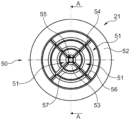
도 5는 도 3의 장치의 부품을 형성할 수 있는 확산기의 일 실시예를 나타내는 사시도이다.
도 6은 도 5의 확산기의 평면도이다.
도 7은 도 6의 선 A-A에 따라 절단된 확산기의 단면도이다.
도 8은 도 3의 장치의 부품을 형성할 수 있는 확산기의 다른 실시예를 나타내는 사시도이다.
도 9는 도 8의 확산기의 평면도이다.
도 10은 도 9의 선 A-A에 따라 절단된 확산기의 단면도이다.
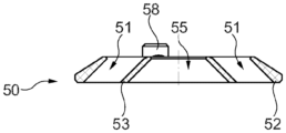
도 11은 도 3의 장치의 부품을 형성할 수 있는 확산기의 다른 실시예를 나타내는 사시도이다.
도 12는 도 11의 확산기의 평면도이다.
도 13은 도 12의 선 A-A에 따라 절단된 확산기의 단면도이다.
도 14는 도 12의 선 B-B에 따라 절단된 확산기의 단면도이다.
도 15는 청구범위에 따르지 않는 장치를 통한 유동을 개략적으로 도시한다.
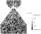
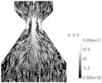
도 16 및 도 17은 본 발명에 따른 장치의 제1 실시예의 CFD 분석 결과를 도시한다.
도 18 및 도 19는 본 발명에 따른 장치의 제2 실시예의 CFD 분석 결과를 도시한다.
도 20 및 도 21은 본 발명에 따른 장치의 제3 실시예의 CFD 분석 결과를 도시한다.BRIEF DESCRIPTION OF THE DRAWINGS Aspects and embodiments of the present invention will now be described by way of example only with reference to the accompanying drawings, which follow.
Figure 1 is a schematic diagram of an apparatus for coating a filter with dry powder.
Figure 2 is a schematic diagram of the components and filters of the device of Figure 1;
Figure 3 is a cross-sectional view of a component of the device of Figure 1;
Fig. 4 is a perspective view of the device of Fig. 3;
Figure 5 is a perspective view of one embodiment of a diffuser that could form part of the device of Figure 3;
Figure 6 is a top view of the diffuser of Figure 5.
Figure 7 is a cross-sectional view of the diffuser taken along line AA in Figure 6.
Figure 8 is a perspective view of another embodiment of a diffuser that may form part of the device of Figure 3;
Figure 9 is a top view of the diffuser of Figure 8.
Figure 10 is a cross-sectional view of the diffuser taken along line AA in Figure 9;
Figure 11 is a perspective view of another embodiment of a diffuser that may form part of the device of Figure 3;
Figure 12 is a top view of the diffuser of Figure 11.
Figure 13 is a cross-sectional view of the diffuser taken along line AA in Figure 12.
Figure 14 is a cross-sectional view of the diffuser taken along line BB in Figure 12.
Figure 15 schematically shows flow through a device that is not in accordance with the claims.
Figures 16 and 17 show CFD analysis results of the first embodiment of the device according to the present invention.
Figures 18 and 19 show CFD analysis results of a second embodiment of the device according to the present invention.
20 and 21 show CFD analysis results of a third embodiment of the device according to the present invention.
본 기술에 숙련된 독자는, 직접적인 문맥이 달리 교시하지 않는 한, 본 발명의 일 태양 또는 실시 형태의 하나 이상의 특징이 본 발명의 임의의 다른 태양 또는 실시 형태의 하나 이상의 특징과 조합될 수 있다는 점을 인식할 것이다.A reader skilled in the art will understand that, unless the immediate context teaches otherwise, one or more features of one aspect or embodiment of the invention may be combined with one or more features of any other aspect or embodiment of the invention. will recognize.
이제, 본 개시에 따른 장치 및 방법의 실시예는 필터, 예를 들어, 배기가스로부터 미립자 물질을 여과하는 필터(2)를 건조 분말로 코팅하는 장치(1)의 개략도를 나타내는 도 1을 먼저 참조하여 설명할 것이다. 필터(2)는 입구 면(3) 및 출구 면(4)을 갖는 다공성 기판을 포함하는 유형으로, 입구 면(3) 및 출구 면(4)은 다공성 구조에 의해 분리된다.Now, for an embodiment of the device and method according to the present disclosure, reference first to Figure 1, which shows a schematic diagram of a device 1 for coating a filter, for example a
장치(1)는 필터(2)를 유지하기 위한 필터 홀더, 입구 통로(5) 및 출구 통로(6)를 포함한다.The device (1) comprises a filter holder for holding the filter (2), an inlet passage (5) and an outlet passage (6).
장치는 또한 예를 들어, 건조 분말의 공급원(7), 분무 장치(8) 및 진공 발생기(9)를 포함할 수 있다.The device may also comprise, for example, a source of dry powder (7), a spraying device (8) and a vacuum generator (9).
필터 홀더는 코팅하는 동안 필터(2)를 고정된 위치에 유지하도록 기능할 수 있다. 필터 홀더는 필터(2)의 상부 단부 및/또는 하부 단부를 파지할 수 있다. 필터 홀더는 필터(2)의 각 상부 단부 및 하부 단부를 지지하는 팽창성 상부 시일 블래더(13)(상부 팽창성 칼라(collar)로 칭하기도 함) 및/또는 팽창성 하부 시일 블래더(14)(하부 팽창성 칼라로 칭하기도 함)를 포함할 수 있다. 팽창성 상부 시일 블래더(13) 및 팽창성 하부 시일 블래더(14)는 필터(2)의 외부 표면과 접촉 및/또는 맞물릴 수 있다. 각각은 필터(2) 주위에 액밀 또는 기밀 시일을 형성할 수 있다. 팽창성 상부 시일 블래더(13) 및 팽창성 하부 시일 블래더(14)는 하나 이상의 하우징에 의해 지지될 수 있다(예를 들어, 하나 이상의 하우징의 내부 벽에 의해 지지됨). 필터(2)는, 필터(2)의 입구 면(3)이 최상부에 위치하도록 수직 방향으로 필터 홀더 내에 배치될 수 있다.The filter holder may function to keep the
공급원(7)은 건조 분말을 포함하고 분무 장치(8)로 수송하기 위한 임의의 적합한 공급원일 수 있다. 예를 들어, 공급원(7)은 호퍼와 같은 저장소를 포함할 수 있다. 공급원(7)은 예를 들어 중량, 부피, 입자 수 또는 시간에 따라 건조 분말을 주입하기 위한 주입 장치를 포함할 수 있다. 공급원(7)은 예를 들어, 건조 분말의 중량 공급 또는 부피 공급과 같은 건조 분말을 분무 장치(8)로 수송하기 위한 수송 장치를 포함할 수 있다. 추가적으로 또는 대안적으로, 분무 장치(8)는 벤츄리 효과를 통해 건조 분말을 분무 장치(8)를 향하여 흡입할 수 있다.The
분무 장치(8)는 건조 분말을 입구 통로(5)로 수송하기 위한 임의의 적합한 장치일 수 있다. 건조 분말은 입구 통로(5) 내로 분무되는 것이 바람직하다. 분무 장치(8)는 건조 분말을 위한 하나 이상의 출구를 포함할 수 있다. 도 1의 실시예에 도시된 바와 같이, 하나 이상의 출구는 하나 이상의 분무 노즐(10)에 제공될 수 있다. 하나 이상의 출구가 건조 분말을 입구 통로(5)로 향하게 하는 방향으로 입구 통로(5)의 외부에 배치될 수 있다. 예를 들어, 도 1의 실시에에 의해 도시된 바와 같이, 하나 이상의 출구가 입구 통로(5)의 입구 상부에 제공될 수 있으며, 여기서, 분무 노즐(10)은 입구 통로(5)의 입구 바로 위에 배치된다. 추가적으로 또는 대안적으로, 하나 이상의 출구가 입구 통로(5) 내부에 배치될 수 있다. 하나 이상의 출구는 입구 통로(5)의 종축에 대해 임의의 적합한 각도로 배향될 수 있다. 예를 들어, 하나 이상의 출구는 종축에 평행한 방향으로 건조 분말을 분무할 수 있다. 하나 이상의 출구는 종축과 일치하도록 정렬될 수 있다.The spraying device 8 can be any suitable device for transporting dry powder to the
분무 장치(8)는 공기와 같은 가압된 가스 공급원(11)을 포함할 수 있으며, 이는 분무 장치(8)의 하나 이상의 출구로부터 건조 분말을 이동시키고 분무하기 위해 제공된다. 예를 들어, 공급원(11)은 공기 입구로부터 공기를 수용하고 공급 라인(12)을 통해 하나 이상의 출구로 압축된 공기를 공급하는 압축기를 갖는 압축 공기 발생기일 수 있다.The nebulizing device 8 may comprise a
출구 통로(6)는 필터 홀더에 의해 유지되는 필터(2)의 출구 면(4)과 사용 중에 연통되는 제1 단부(31) 및 진공 발생기(9)와 연통되는 제2 단부(32)를 포함한다. 진공 발생기(9)는 출구 통로(6)를 통해 필터(2)의 출구 면(4)에 압력 감소를 적용함으로써, 입구 통로(5) 및 필터(2)의 다공성 구조를 통과한 1차 가스 유동을 사용 중에 확립하기 위해 제공될 수 있다. 출구 통로(6)의 제1 단부(31)는 출구 면(4)에 직접 또는 간접적으로 결합될 수 있다. 제1 단부(31)는 필터(2)의 출구 면(4)에 맞물리는 더 넓은 단부와 진공 발생기(9)로 연결되는 도관(16)과 연통되는 더 좁은 단부를 갖는 깔때기를 정의할 수 있는 진공 콘(15)의 형태일 수 있다. 팽창성 하부 시일 블래더(14)는 필터(2)의 출구 면(4)과 진공 콘(15) 사이에 시일을 형성할 수 있다.The outlet passage 6 includes a
진공 발생기(9)는 도관(16)에 의해 진공 콘(15)에 연결된 진공 펌프(17)를 포함할 수 있다. 진공 펌프(17)는 1차 가스 유동의 체적 유량(volumetric flow rate)을 제어하도록 제어기에 의해 제어될 수 있다.The vacuum generator 9 may comprise a
진공 발생기(9) 및/또는 출구 통로(6)에는 체적 유량 센서가 제공될 수 있다. 체적 유량 센서는 도관(16)을 따라 배치된 하나 이상의 압력 센서(18)와 조합된 오리피스 플레이트일 수 있다. 장치(1)는 필터(2)의 배압을 모니터링하기 위한 압력 센서를 추가로 포함할 수 있다. 단일 압력 센서가 사용될 수 있다. 단일 압력 센서는 진공 발생기(9), 도관(16) 또는 진공 콘(15)에 배치될 수 있다.The vacuum generator 9 and/or the outlet passage 6 may be provided with a volumetric flow sensor. The volumetric flow sensor may be an orifice plate combined with one or
제어기는 예를 들어, 진공 발생기(9) 및 분무 장치(8)의 작동을 제어할 수 있다. 제어기는 또한 진공 발생기(9)에 의해 생성된 1차 가스 유동을 제어하는 것과는 독립적으로 건조 분말을 공급원(7)으로부터 분무 장치(8)로 수송하는 것을 제어하도록 구성될 수 있다. 예를 들어, 제어기는 공급원(7)의 주입 장치의 작동을 제어할 수 있다. 제어기는 1차 가스 유동을 제어하는 것과는 독립적으로 건조 분말을 필터(2)의 입구 면(3)을 향해 분무하는 것을 제어하도록 구성될 수 있다. 본 명세서에서 "독립적으로"라는 용어의 사용은 제어기가 건조 분말의 분무 및 1차 가스 유동의 각 변수를 다른 변수의 상태와 관계없이 개별적으로 제어할 수 있는 기능을 의미한다. 예를 들어, 제어기는 건조 분말을 동시에 분무하지 않고 1차 가스 유동을 확립할 수 있다. 예를 들어, 제어기는 1차 가스 유동의 체적 유량을 변경하지 않고 건조 분말의 분무 속도를 증가시키거나 줄일 수 있다. 예를 들어, 제어기는 건조 분말의 분무 속도를 변경하지 않으고 1차 가스 유동의 체적 유량을 증가시키거나 줄일 수 있다. 예를 들어, 제어기는 진공 발생기(9)의 작동을 제어하는 것과는 독립적으로 분무 장치(8)의 작동을 제어할 수 있다.The controller can control the operation of the vacuum generator 9 and the atomizing device 8, for example. The controller may also be configured to control the transport of dry powder from the
입구 통로(5)는 건조 분말과 가스의 혼합물을 수용하는 데 적합하다. 예를 들어, 가스는 진공 발생기(9)의 작동에 의해 생성된 1차 가스 유동 및/또는 분무 장치(8)로부터의 가스 유동일 수 있다. 예를 들어, 진공 발생기(9)의 작동은 가스가 입구 통로(5)의 입구(20)로 흡입되도록 1차 가스 유동을 설정할 수 있다. 입구(20)는 가스가 대기로부터 직접 입구(20)로 흡입되도록 주변 대기에 개방될 수 있다. 대안적으로, 입구(20)는 가스가 상류 도관으로부터 입구(20)로 흡입되도록 상기 상류 도관에 결합될 수 있다.The
분무 장치(8)로부터의 가스 유동이 입구 통로(5)로 주입될 수 있다. 도 1의 도시된 실시예에서, 가스는 진공 발생기(9)에 의해 생성된 흡입력에 의해 대기로부터 입구(20)로 흡입되고, 분무 장치(8)에 의해 (건조 분말과 함께) 추가 가스가 주입되는 두 가지 효과로 인해 입구 통로(5)로 유입된다.A gas flow from the nebulizing device (8) can be injected into the inlet passage (5). In the illustrated embodiment of Figure 1, gas is drawn from the atmosphere into the
건조 분말과 가스의 혼합은 입구 통로(5)에서 발생할 수 있다. 또한, 건조 분말과 가스의 혼합은 건조 분말이 입구 통로(5)에 도달하기 전에, 예를 들어 분무 장치(8) 및/또는 입구 통로(5)의 상류에 연결된 임의의 도관에서 발생할 수 있다.Mixing of dry powder and gas may occur in the
입구 통로(5)는 필터 홀더에 의해 유지된 필터(2)의 입구 면(3)과 사용 중에 연통한다.The
도 2에 개략적으로 도시된 바와 같이, 입구 통로(5)는 확산기(21) 및 확산기(21)의 하류에 있는 발산 부분(22)을 포함하며, 이는 필터(2)의 유입 면(3)을 향해 외향으로 테이퍼 형성되거나 다른 방식으로 유동을 위해 면적이 증가한다. 또한, 입구 통로(5)는 수렴 부분(23) 및 목 부분(24)을 포함할 수 있다.As schematically shown in FIG. 2 , the
발산 부분(22)은 가스 및 건조 분말이 필터(2)의 입구 면(3)을 향해 유동하는 것을 제한하고 채널링하는 기능을 한다. 발산 부분(22)은 관형일 수 있다. 발산 부분(22)은 원추형일 수 있다. 도 2에 도시된 바와 같이, 발산 부분(22)은 10° 내지 80°, 선택적으로 40° 내지 60°, 선택적으로 45° 내지 55°의 각도 α로 외향으로 테이퍼 형성될 수 있다. 발산 부분(22)의 벽은 포괄적인 각도가 20° 내지 160°, 선택적으로 80° 내지 120°, 선택적으로 90° 내지 110°일 수 있다.The diverging portion (22) functions to restrict and channel the flow of gases and dry powder towards the inlet face (3) of the filter (2). The diverging
발산 부분(22)은 축 방향 길이 L a 가 50 내지 300 mm일 수 있다. 발산 부분(22)의 상류 단부(25)는 내경 D a 가 40 내지 100 mm일 수 있다. 이 내경 D a 는 상기 목 부분(24)의 내경 D c 와 동일할 수 있다. 발산 부분(22)의 하류 단부(26)는 내경 D b 가 필터(2)의 입구 면(3)의 직경과 실질적으로 동일할 수 있다. 하류 단부(26)는 원형, 타원형 또는 다른 형태일 수 있다. 하류 단부(26)의 형태는 필터(2)의 입구 면(3)의 형태와 일치할 수 있다.The diverging
유입 통로(5)는 하류 단부(26)와 필터(2)의 입구 면(3) 사이에 추가적인 관형 부분(33)을 더 포함할 수 있다. 추가적인 관형 부분(33)은 원통형일 수 있다. 추가적인 관형 부분(33)의 하류 단부는 원형, 타원형 또는 다른 형태일 수 있다. 이 형태는 필터(2)의 입구 면(3)의 형태와 일치할 수 있다.The
존재하는 경우, 목 부분(24)은 확산기(21)와 발산 부분(22) 사이에 배치된다. 목 부분(24)은 원통형일 수 있으며, 축 방향 길이 L b 가 0 내지 40 mm, 선택적으로 5 내지 40 mm, 선택적으로 10 내지 30 mm, 선택적으로 5 mm, 10 mm, 15 mm, 20 mm 또는 25 mm일 수 있다. 목 부분(24)의 내경 D c 는 40 내지 100 mm일 수 있다.If present, the
수렴 부분(23)은 목 부분(24) 및/또는 발산 부분(22)을 향해 내향으로 테이퍼 형성되거나 다른 방식으로 유동을 위해 면적이 줄어들 수 있다. 수렴 부분(23)은 가스 및 건조 분말이 목 부분(24) 및/또는 발산 부분(22)을 향해 유동하는 것을 제한하고 채널링하는 기능을 한다. 수렴 부분(23)은 관형일 수 있다. 수렴 부분(23)은 원추형일 수 있다. 수렴 부분은 40° 내지 60°, 선택적으로 45° 내지 55°의 각도 β로 내향으로 테이퍼 형성될 수 있다. 수렴 부분(23)의 벽은 포괄적인 각도가 80° 내지 120°, 선택적으로 90° 내지 110°일 수 있다.The converging
수렴 부분(23)은 축 방향 길이 L c 가 50 내지 300 mm일 수 있다. 수렴 부분(23)의 상류 단부(27)의 내경 D d 는 140 내지 700 mm일 수 있다. 수렴 부분(23)의 하류 단부(28)의 내경 D e 는 40 내지 100 mm일 수 있다. 이 내경 D e 는 목 부분(24)의 내경 D c 와 동일할 수 있다.The converging
입구 통로(5)는 수렴 부분(23)의 상류 단부(27)의 상류에 추가 관형 부분(29)을 추가로 포함할 수 있다. 추가적인 관형 부분(29)은 원통형일 수 있다.The
확산기(21)는 수렴 부분(23)의 출구에 배치되거나 이에 인접하게 배치될 수 있으며, 즉 목 부분(24) 또는 발산 부분(22)(목 부분이 존재하지 않는 경우)에 연결되는 하류 단부(28)에 배치되거나 이에 인접하게 배치될 수 있다. 일부 실시예에서, 확산기(21)는 목 부분(24)에 배치될 수 있다. 그러나, 확산기(21)는 목 부분(24)의 입구, 예를 들어 수렴 부분(23)의 하류 단부(28)에 배치되거나 이에 인접한(예를 들어, 바로 상류에 위치하는) 수렴 부분(23) 내에 배치되는 것이 바람직하다.The
목 부분(24)의 내경 D c 는 확산기(21)의 외경 이하일 수 있다.The inner diameter D c of the
바람직하게는, 입구 통로(5)는 확산기(21)와 입구 통로(5)의 벽 사이에 바이패스 유동 간격(30)을 추가로 포함한다. 예를 들어, 바이패스 유동 간격(30)은 확산기(21)의 환형 외부 에지와 입구 통로(5)의 관형 벽, 예를 들어 수렴 부분(23)의 원추형 벽 사이의 환형 간격일 수 있다. 환형 간격의 폭은 1 내지 5 mm, 선택적으로 3 mm일 수 있다.Preferably, the inlet passageway (5) further comprises a bypass flow gap (30) between the diffuser (21) and the wall of the inlet passageway (5). For example, the
일부 실시예에서, 입구 통로(5)는 목 부분(24)의 출구, 바람직하게는 목 부분(24) 내에 배치되거나 이에 인접하게 배치된 제2 확산기를 추가로 포함할 수 있다.In some embodiments, the
도 3 및 도 4는 입구 통로(5)의 실시예를 보다 상세하게 도시하고 추가적인 구조적 세부 사항을 설명한다. 입구 통로(5)는 지지 플레이트(35)에 장착되며, 특히 수렴 부분(23)의 상류 단부(27)의 플랜지는 볼트(36)에 의해 지지 플레이트(35)의 밑면에 고정된다. 도 4에 도시된 바와 같이, 호퍼 형태의 건조 분말용 공급원(7)은 또한 지지 암(37) 및 지지 링(38)을 통해 지지 플레이트(35)에 장착된다. 분무 노즐(10) 형태의 분무 장치(8)는 클램프 및 시일 배열(39)을 사용하여 호퍼에 의존하도록 장착된다.3 and 4 show an embodiment of the
확산기(21)는 확산기 홀더를 통해 지지 링(38) 및 지지 플레이트(35)에 장착된다. 도 3 및 도 4의 실시예에서, 확산기 홀더는 추가적인 관형 부분(29)을 통해 그리고 수렴 부분(23) 내에서 하향으로 연장되는 두 개의 L 자형 타이 로드(40)를 포함한다. 도 3에 도시된 바와 같이, 타이 로드(40)는 확산기(21)를 위에서부터 지지한다. 이러한 방식으로, 바이패스 유동 간격(30)은 중단되지 않고 유지될 수 있으며, 즉 확산기(21)의 전체 원주 주위에 연속적인 환형 간격을 형성할 수 있다.The
도 3에 도시된 바와 같이, 입구 통로(5)는 하나 초과의 피스로 형성될 수 있다. 예를 들어, 입구 통로(5)는 조립 및 분해 가능한 두 개 이상의 부품을 갖는 모듈형 시스템일 수 있다. 예를 들어, 모듈형 시스템은 수렴 부분(23)을 포함하는 제1 부품과 발산 부분(22)을 포함하는 제2 부품을 가질 수 있다. 제1 부품 및/또는 제2 부품은 선택적으로 목 부분(24)의 적어도 일부를 포함할 수 있다. 대안적으로, 목 부분(24)은 모듈형 시스템의 제3 부분으로 구성될 수 있다.As shown in Figure 3, the
제1 부품과 제2 부품을 함께 조립하기 위해 클램프 및 시일 배열 또는 다른 적합한 수단이 제공될 수 있다. 예를 들어, 도 3의 예시적인 실시예에서, 클램프 및 시일 배열(41)은 제1 부품과 제2 부품을 조인트에서 함께 결합하기 위해 제공될 수 있다. 조인트는 목 부분(24) 내에 제공될 수 있다.Clamp and seal arrangements or other suitable means may be provided for assembling the first and second parts together. For example, in the exemplary embodiment of Figure 3, a clamp and
모듈형 시스템은 복수의 상이한 제2 부품으로 구성될 수 있으며, 각 제2 부품은 발산 부분(22)의 상이한 구성을 가질 수 있다. 예를 들어, 각 제2 부품은 축 방향 길이 La, 내경 Da, 내경 Db, 각도 α 및 하류 단부(26)의 단면 형상 중 하나 이상에서 상이할 수 있다. 제2 부품은 각각 선택적으로 동일한 제1 부품에 조립될 수 있다. 이러한 방식으로, 입구 통로(5)는 예를 들어, 수렴 부분(23)과 확산기(21)를 포함하는 제1 부품의 구성 또는 위치를 변경할 필요 없이, 상이한 필터(2) 및/또는 상이한 공정에 사용하도록 용이하게 구성될 수 있다. 따라서, 제1 부품은 입구 통로(5)의 영구적 또는 베이스 부분으로 구성될 수 있고, 제2 부품은 입구 통로(5)의 교체 가능한 부품으로 구성될 수 있다.The modular system may be comprised of a plurality of different second components, each of which may have a different configuration of the
발산 부분(22)의 하류 단부(26)에는 입구 통로(5)를 필터(2)에 결합하기 위한 시일(42), 예를 들어 팽창성 칼라가 제공될 수 있다. 이 시일은 필터 홀더의 팽창성 상부 시일 블래더(13) 또는 추가적인 시일일 수 있다.The
입구 통로(5)는 필터(2)의 입구 면(3)과 선택적으로 맞물릴 수 있는 헤드셋의 일부를 형성할 수 있다. 상기 입구 통로의 총 축 방향 길이 L d 는 400 mm 이하, 선택적으로 350 mm 이하일 수 있다.The
확산기(21)는 안내 표면 및 개구를 포함한다. 안내 표면은 가스 및 건조 분말이 확산기(21)를 패스 오버 및/또는 통과할 때 유동을 안내하는 기능을 한다. 개구는 가스와 건조 분말이 확산기(21)를 통과할 수 있도록 하는 기능을 한다. 안내 표면은 가스 내 건조 분말의 혼합을 촉진하고, 가스 유동 내에서 건조 분말 입자의 분포를 변경할 수 있다. 따라서, 안내 표면은 가스 유동 내에서 건조 분말의 분포를 변경할 수 있다. 안내 표면은 확산기(21)의 종축에 대해 경사각이 30° 내지 60°, 선택적으로 45°일 수 있다. 안내 표면은 외향으로 테이퍼 형성되는 데, 즉 안내 표면 위를 통과하는 가스 및 건조 분말의 유동이 입구 통로(5)의 관형 벽을 향해 외측으로 향하도록 하는 것이 바람직하다. 발산 부분(22)의 외향 테이퍼 각도 α는 확산기(21)의 안내 표면의 경사각과 동일할 수 있다.
확산기(21)는 회전 대칭 순서가 2, 3, 4 또는 그 이상일 수 있다.
도 5 내지 도 7은 장치(1)의 확산기(21)의 일 실시예를 나타낸다. 확산기(21)는 복수의 개구(51)를 포함하는 플레이트(50)를 포함한다. 플레이트(50)는 원형과 같은 원판형일 수 있다. 플레이트(50)는 사이에 개구(51)가 배치된 외부 링(52)과 내부 링(53)을 포함할 수 있다. 하나 이상의 리브(54)는 외부 링(52)과 내부 링(53)을 연결할 수 있다. 도시된 바와 같이, 네 개의 개구(51)를 정의하는 네 개의 리브(54)가 제공될 수 있으며, 리브(54)는 방향이 방사형일 수 있다. 내부 링(53)은 중앙 개구(55)를 포함할 수 있다.5 to 7 show one embodiment of the
외부 링(52) 및 내부 링(53)의 표면은 확산기(21)의 안내 표면을 구성한다. 특히, 상부 표면(사용 시 상류를 향하는 표면)이 안내 표면을 형성할 수 있다. 도 7에 도시된 바와 같이, 외부 링(52) 및 내부 링(53)의 상부 면은 확산기(21)의 종축에 대해 경사각이 30° 내지 60°, 선택적으로 45°일 수 있다.The surfaces of the
이 확산기(21)의 회전 대칭 순서는 4이다.The rotational symmetry order of this
도 8 내지 도 10은 장치(1)의 확산기(21)의 다른 실시예를 나타낸다. 확산기(21)는 이전 실시예와 유사하지만 네 개의 링, 외부 링(52), 내부 링(53) 및 두 개의 중간 링(56, 57)을 포함한다. 따라서, 세 개의 환형 배열의 개구(51)가 중앙 개구(55)와 함께 제공된다.8 to 10 show another embodiment of the
도 11 내지 도 14는 장치(1)의 확산기(21)의 다른 실시예를 나타낸다. 확산기(21)는 제1 실시예와 유사하지만 네 개가 아닌 세 개의 리브(54)를 포함한다. 또한, 타이 로드(40)에 연결하기 위한 장착 지점(58)이 확산기(21)의 상면에 제공된다.11 to 14 show another embodiment of the
이 확산기(21)는 회전 대칭 순서가 3이다.This
장치(1), 및 특히 유입 통로(5)는 하나 이상의 내화 분말을 포함하거나 이로 구성된 건조 분말, 선택적으로 하나 이상의 건식 내화 분말 및/또는 하나 이상의 에어로겔을 포함하는 건조 분말로 필터를 코팅하는 데 사용될 수 있다. 추가적으로 또는 대안적으로, 장치(1)는 금속 산화물을 열 분해하여 형성하기 위한 금속 화합물을 포함하거나 또는 이로 구성된 건조 분말로 필터를 코팅하는 데 사용될 수 있다. 실시예에서, 금속 화합물은 금속 수산화물, 금속 인산염, 금속 탄산염, 금속 황산염, 금속 과염소산염, 금속 요오드화물, 금속 옥살산염, 금속 아세트산염, 금속 염소산염 또는 이들의 혼합물을 포함하거나 이로 이루어질 수 있다.The device (1), and in particular the inlet passage (5), is used for coating the filter with a dry powder comprising or consisting of at least one refractory powder, optionally comprising at least one dry refractory powder and/or at least one airgel. You can. Additionally or alternatively, device 1 may be used to coat the filter with a dry powder comprising or consisting of a metal compound to form metal oxides by thermal decomposition. In embodiments, the metal compound may include or consist of a metal hydroxide, metal phosphate, metal carbonate, metal sulfate, metal perchlorate, metal iodide, metal oxalate, metal acetate, metal chlorate, or mixtures thereof.
건조 분말로 코팅되는 필터(2)는 건조 분말로 코팅되기 전에 당업계에 알려진 바와 같은 촉매 코팅이 제공될 수 있다. 당업계에 알려진 바와 같은 방법에 따라 촉매 슬러리로부터 제조된 워시코트가 사용될 수 있다. 워시코트는 예를 들어 탄화수소 트랩, 삼원 촉매(TWC), NOx 흡수제, 산화 촉매, 선택적 촉매 환원(SCR) 촉매, 희박 NOx 촉매, 및 이들 중 임의의 둘 이상의 조합일 수 있다. 필터(2)는 촉매 코팅을 도포한 후에 하소될 수 있다.The
장치(1)의 사용 예에서, 필터(2)는 먼저 필터 홀더 내에 로드될 수 있다. 필터(2)는 처리 동안 고정 위치에 유지될 수 있다. 필터(2)는 필터 홀더에 의해 필터(2)의 상부 단부 및/또는 하부 단부에 파지될 수 있다. 팽창성 상부 시일 블래더(13) 및 팽창성 하부 시일 블래더(14)는 필터(2)의 외부 표면과 접촉 및/또는 맞물리도록 팽창될 수 있다. 필터(2)는 필터의 입구 면(3)이 최상부에 있는 수직 방향으로 유지될 수 있다. 필터 홀더의 작동, 예를 들어 팽창성 상부 시일 블래더(13) 및 팽창성 하부 시일 블래더(14)의 팽창은 제어기에 의해 제어될 수 있다.In an example of use of device 1,
진공 발생기(9)는 입구 통로(5), 필터(2) 및 출구 통로(6)를 통해 1차 가스 유동을 확립하기 위해 제어기에 의해 활성화될 수 있다. 선택적으로, 1차 가스 유동은 건조 분말이 분무 장치(8)의 분무 노즐(10)로 수송되어 필터(2)의 입구 면(3)을 향해 분무되기 전에 확립된다. 진공 발생기(9)에 의해 생성된 압력 감소의 수준은 공급원(7)으로부터 분무 장치(8)로의 건조 분말의 수송 속도 또는 질량 속도와 무관하게 제어기에 의해 제어될 수 있다. 1차 가스 유동은 10 m3/hr 내지 5,000 m3/hr, 선택적으로 400 m3/hr 내지 2,000 m3/hr, 선택적으로 600 m3/hr 내지 1000 m3/hr의 체적 유량을 가질 수 있다.The vacuum generator 9 can be activated by a controller to establish primary gas flow through the
건조 분말은 분무 장치(8)에 의해 필터(2)의 입구 면(3)을 향해 입구 통로(5)로 분무될 수 있다. 건조 분말은 추가적인 관형 부분(29)과 수렴 부분(23)을 따라 확산기(21)를 향해 통과한다.The dry powder can be sprayed into the
가스와 건조 분말이 수렴 부분(23)을 통과할 때, 건조 분말의 입자는 가스 유동에서 입자가 혼합되는 혼합 효과(blending effect)를 겪을 수 있다.As the gas and dry powder pass through the converging
확산기(21)에 도달하면, 가스 및 건조 분말의 적어도 일부가 확산기(21)의 안내 표면을 패스 오버하고 확산기(21)의 개구(51)를 통과할 수 있다. 가스 및 건조 분말의 일부가 중앙 개구(55)를 통과할 수 있다. 일부 가스 및 건조 분말은 안내 표면에 의해 확산기의 외부 주위를 유동하여, 즉 환형 바이패스 유동 간격(30)을 통과하도록 안내될 수 있다. 예를 들어, 외부 링(52)에 접촉하는 가스 및 건조 분말에 대해 이것이 발생할 수 있다. 가스 및 건조 분말의 일부는 확산기(21)에 먼저 접촉하지 않고 환형 바이패스 유동 간격(30)을 통과할 수 있다. 예를 들어, 이는 입구 통로의 관형 벽에 가깝게 유동하는 가스 및/또는 건조 분말, 즉 관형 벽을 따른 층류의 경우 발생할 수 있다.Upon reaching the
확산기는 가스 유동에서 건조 분말을 추가로 혼합하고 재분배하는 역할을 한다.The diffuser serves to further mix and redistribute the dry powder in the gas flow.
확산기(21)를 빠져나오거나 바이패스한 후, 가스 및 건조 분말은 추가 혼합이 발생할 수 있는 목 부분(24)을 통과한다.After exiting or bypassing the
이어서, 가스 및 건조 분말은 발산 부분(22)을 통과한다. 유리하게는, 발산 부분(22)은 유동 단면에 걸쳐 건조 분말 입자를 더 균일하게 분배하는 작용을 할 수 있고, 특히 필터(2)의 입구 면(3)의 주변 에지로 건조 분말의 유동에 도움이 될 수 있다. 이는 필터(2)로 유입되는 건조 분말이 입구 면(3)을 걸쳐 더 균일하게 분포되도록 하는 데 도움이 될 수 있다.The gas and dry powder then pass through the diverging section (22). Advantageously, the diverging
코팅하는 동안 필터(2)의 배압을 모니터링할 수 있다. 배압은 압력 센서를 사용하여 모니터링할 수 있다. 제어기는 예를 들어, 미리 결정된 배압에 도달하면 필터(2)의 입구 면(3)을 향한 건조 분말의 분무를 중지하도록 구성될 수 있다. 미리 결정된 배압은 절대 배압일 수 있다. 절대 배압은 600 m3/hr의 유량에서 20 내지 180 mbar 일 수 있다. 대안적으로, 미리 결정된 배압은 상대 배압일 수 있다. 추가로 또는 대안적으로, 필터(2)의 입구 면(3)을 향한 건조 분말의 분무는 미리 결정된 총 분무 시간에 도달하면 중지될 수 있다.The back pressure of the filter (2) can be monitored during coating. Back pressure can be monitored using a pressure sensor. The controller may be configured, for example, to stop spraying the dry powder towards the
본 방법은 건조 분말의 10 내지 40 g/l, 선택적으로 15 내지 30 g/l, 선택적으로 약 20 g/l의 필터의 최대 로딩을 전달하도록 구성될 수 있거나; 또는, 건조 분말의 <10 g/l, 선택적으로 < 5 g/l, 선택적으로 <2 g/l 의 필터의 최대 로딩을 전달하도록 구성될 수 있다.The method may be configured to deliver a maximum loading of the filter of 10 to 40 g/l of dry powder, optionally 15 to 30 g/l, optionally about 20 g/l; Alternatively, it may be configured to deliver a maximum loading of the filter of <10 g/l, optionally <5 g/l, optionally <2 g/l of dry powder.
실시예Example
도 15는 확산기가 제공되지 않은 입구 통로를 통한 건조 분말 및 가스의 유동을 나타낸다. 목 부분과 발산 부분의 존재로 인해 가스 유동에서 건조 분말이 일부 확산되고 혼합되는 것을 볼 수 있다. 그러나, 그 결과 분말 분산물은 필터 입구 면의 중앙 영역에 심하게 집중되며, 입구 면의 주변 영역에 도달하는 건조 분말은 거의 없다.Figure 15 shows the flow of dry powder and gas through an inlet passage without a diffuser. Due to the presence of the throat and divergence parts, some diffusion and mixing of the dry powder can be seen in the gas flow. However, the resulting powder dispersion is heavily concentrated in the central area of the filter inlet face, with little dry powder reaching the peripheral areas of the inlet face.
도 16 및 도 17은 본 발명에 따른 장치(1)의 제1 실시예에 대한 CFD 분석 결과를 나타낸다. 이 실시예에서, 목 부분(24)의 축 방향 길이 L b 는 5 mm이다. 확산기(21)는 도 8 내지 도 10에 도시된 유형이다.16 and 17 show CFD analysis results for the first embodiment of the device 1 according to the present invention. In this embodiment, the axial length L b of the
CFD 분석에 따르면, 도 15의 실시예에 비해, 건조 분말이 필터의 전체 입구 면에 걸쳐 더 균일하게 분포된다는 것을 보여준다. 특히, 확산기와 발산 부분의 조합 효과로 인해 건조 분말이 입구 면의 주변 영역에까지 도달할 수 있다. 또한, 발산 부분의 유동에 일부 비교적 큰 규모의 와류가 포함되어 있음을 알 수 있다. 이러한 와류는 건조 분말과 가스 유동의 혼합을 촉진하는 데 유익할 수 있다. 그러나, 도시된 바와 같이, 이들은 또한 중앙과 주변부 사이의 입구 면의 중간 영역에서 입구 면을 실질적으로 따라(예를 들어, 종축을 걸쳐) 입구 면의 영역에서 일부 유동을 초래할 수 있다. 이러한 유동은 입구 면 표면의 채널 벽에 쌓인 건조 분말을 제거하는 역할을 할 수 있다는 점에서 유익할 수 있다. 그러나, 입구 면을 걸쳐 채널에 유입되는 건조 분말의 양이 일부 불균일해지는 결과를 초래할 수 있다.CFD analysis shows that compared to the example of Figure 15, the dry powder is more evenly distributed across the entire inlet face of the filter. In particular, the combined effect of the diffuser and the diverging part allows the dry powder to reach the surrounding area of the entrance face. Additionally, it can be seen that the flow in the divergent part contains some relatively large-scale vortices. These vortices can be beneficial in promoting mixing of the dry powder and gas flow. However, as shown, they may also result in some flow in a region of the inlet face substantially along the inlet face (eg, across the longitudinal axis) in an intermediate region of the inlet face between the center and the periphery. This flow can be beneficial in that it can serve to remove dry powder that has accumulated on the channel walls on the inlet surface. However, this may result in some non-uniformity in the amount of dry powder entering the channel across the inlet surface.
도 18 및 도 19는 본 발명에 따른 장치(1)의 제2 실시예에 대한 CFD 분석 결과를 나타낸다. 이 실시예에서, 목 부분(24)의 축 방향 길이 L b 는 10 mm이다. 확산기(21)는 도 8 내지 도 10에 도시된 유형이다.18 and 19 show CFD analysis results for the second embodiment of the device 1 according to the present invention. In this embodiment, the axial length L b of the
CFD 분석은, 도 15의 실시예에 비해, 건조 분말이 필터의 입구 면 전체에 걸쳐 더 균일하게 분포되어 있음을 다시 한 번 나타낸다. 특히, 확산기와 발산 부분의 조합 효과로 인해 건조 분말이 입구 면의 주변 영역에까지 도달할 수 있다. 또한, 도 16 및 도 17의 실시예에 비해 발산 부분 내의 와류가 현저히 감소한 것을 알 수 있다. 유리하게는, 입구 면 근처의 영역에서 전체 입구 면을 걸쳐 유동은 종축에 실질적으로 평행하고, 도 16 및 도 17의 실시예에서 경험한 횡방향 유동이 제거되었다. 그러나, 입구 필터의 표면을 걸쳐 건조 분말의 양에 일부 불균일성이 있는 것이 분명하다. 예를 들어, 중앙과 주변부에 유입되는 건조 분말의 양이 중간 영역보다 약간 더 많다.The CFD analysis again shows that compared to the example in Figure 15, the dry powder is more evenly distributed across the inlet face of the filter. In particular, the combined effect of the diffuser and the diverging part allows the dry powder to reach the surrounding area of the entrance face. In addition, it can be seen that the eddy currents in the diverging part are significantly reduced compared to the embodiments of FIGS. 16 and 17. Advantageously, in the region near the inlet face the flow across the entire inlet face is substantially parallel to the longitudinal axis and the transverse flow experienced in the embodiments of FIGS. 16 and 17 is eliminated. However, it is clear that there is some non-uniformity in the amount of dry powder across the surface of the inlet filter. For example, the amount of dry powder entering the center and periphery is slightly greater than the middle region.
도 20 및 도 21은 본 발명에 따른 장치(1)의 제3 실시예에 대한 CFD 분석 결과를 나타낸다. 이 실시예에서, 목 부분(24)의 축 방향 길이 L b 는 10 mm이다. 확산기(21)는 도 5 내지 도 7에 도시된 유형이다.20 and 21 show CFD analysis results for the third embodiment of the device 1 according to the present invention. In this embodiment, the axial length L b of the
CFD 분석은 건조 분말이 필터의 입구 면 전체에 걸쳐 더 균일하게 분포되어 있음을 나타낸다. 도 18 및 도 19의 실시예와 유사하게, 입구 면에 유입되는 유동은 전체 입구 면을 걸쳐 종축에 실질적으로 평행한다. 또한, 유동은 입구 면에 걸쳐 매우 균일하며 도 18 및 도 19의 실시예보다 더 균일하다. 발산 부분에서의 와류가 실질적으로 제거되고, 입구 면으로 유입되는 유동이 매우 안정적이라는 것은, 입구 면 위의 상당한 거리 동안 입구 면에 걸쳐 유동 라인이 직선으로 평행하다는 사실에서 알 수 있다.CFD analysis indicates that the dry powder is more evenly distributed across the inlet face of the filter. Similar to the embodiment of Figures 18 and 19, the flow entering the inlet face is substantially parallel to the longitudinal axis across the entire inlet face. Additionally, the flow is very uniform across the inlet face, more uniform than the embodiments of Figures 18 and 19. That the vortices in the divergent part are substantially eliminated and the flow entering the inlet face is very stable can be seen from the fact that the flow line is straight and parallel across the inlet face for a considerable distance above the inlet face.
본 발명의 장치는 다양한 형태 및 크기의 필터를 코팅하도록 구성될 수 있다.The device of the present invention can be configured to coat filters of various shapes and sizes.
비제한적인 일 실시예에서, 입구 통로(5)는 직경 330.2 mm의 기판을 코팅하기 위해 다음과 같은 치수로 구성된다:In one non-limiting example, the
![]()
![]()
발산 부분(22)의 축 방향 길이 L a 는 225 mm이며; The axial length L a of the diverging
발산 부분(22)의 상류 단부(25)는 내경 D a 가 73 mm이고; The
발산 부분(22)의 하류 단부(26)는 내경 D b 가 335 mm이며; The
목 부분(24)의 축 방향 길이 L b 는 28 mm이고; The axial length L b of the
목 부분(24)의 내경 D c 는 73 mm이며; The inner diameter D c of the
수렴 부분은 수렴 부분(23)의 벽이 90°의 포괄적인 각도를 갖도록 45°의 각도 β로 내향으로 테이퍼 형성되고; The converging portion is tapered inwardly at an angle β of 45° such that the wall of the converging
수렴 부분(23)의 축 방향 길이 L c 는 112 mm이며; The axial length L c of the converging
수렴 부분(23)의 상류 단부(27)는 내경 D d 가 196 mm이고; 및 The
수렴 부분(23)의 하류 단부(28)는 내경 D e 가 73 mm이다. The
본 개시내용의 추가의 태양 및 실시 형태가 하기의 항목에 제시되어 있다:Additional aspects and embodiments of the disclosure are presented in the sections below:
항목 A1. 필터를 건조 분말로 코팅하는 장치로서, 상기 장치는,Item A1. A device for coating a filter with dry powder, the device comprising:
i) 필터를 유지하기 위한 필터 홀더; i) a filter holder to hold the filter;
ii) 건조 분말과 가스의 혼합물을 수용하기 위한 입구 통로로서, 상기 입구 통로는 상기 필터 홀더에 의해 유지되는 상기 필터의 입구 면과 사용 중에 연통되는 입구 통로; 및 ii) an inlet passage for receiving a mixture of dry powder and gas, the inlet passage communicating during use with an inlet face of the filter held by the filter holder; and
iii) 필터 홀더에 의해 유지되는 필터의 출구 면과 사용 중에 연통되는 제1 단부 및 진공 발생기와 연통되는 제2 단부를 포함하는 출구 통로를 포함하고; iii) an outlet passage comprising a first end in communication with the outlet face of the filter held by the filter holder and a second end in communication with the vacuum generator;
상기 입구 통로는,The entrance passage is,
확산기; 및 diffuser; and
상기 확산기의 하류에 있는, 상기 필터의 상기 입구 면을 향해 외향으로 테이퍼 형성되거나 다른 방식으로 유동을 위해 면적이 증가하는 발산 부분을 포함하는, 장치. and a diverging portion downstream of the diffuser that tapers outwardly toward the inlet face of the filter or otherwise increases in area for flow.
항목 A2. 항목 A1에 있어서, 발산 부분은 원추형인, 장치.Item A2. The device of item A1, wherein the diverging portion is conical.
항목 A3. 항목 A1 또는 항목 A2에 있어서, 상기 발산 부분은 10° 내지 80°, 선택적으로 40° 내지 60°, 선택적으로 45° 내지 55°의 각도로 외향으로 테이퍼 형성되는, 장치.Item A3. The device of item A1 or item A2, wherein the diverging portion is tapered outwardly at an angle of 10° to 80°, optionally 40° to 60°, optionally 45° to 55°.
항목 A4. 임의의 선행하는 항목에 있어서, 상기 발산 부분은 축 방향 길이가 50 내지 300 mm인, 장치.Item A4. The device of any preceding clause, wherein the diverging portion has an axial length of 50 to 300 mm.
항목 A5. 임의의 선행하는 항목에 있어서, 상기 입구 통로는 상기 확산기와 상기 발산 부분 사이에 목 부분을 추가로 포함하는, 장치.Item A5. The device of any preceding clause, wherein the inlet passageway further comprises a neck portion between the diffuser and the divergent portion.
항목 A6. 항목 A5에 있어서, 상기 목 부분은 원통형인, 장치.Item A6. The device of item A5, wherein the neck portion is cylindrical.
항목 A7. 항목 A5 또는 항목 A6에 있어서, 상기 목 부분은 축 방향 길이가 0 내지 40 mm, 선택적으로 5 내지 40 mm, 선택적으로 10 내지 30 mm, 선택적으로 5 mm, 10 mm, 15 mm, 20 mm 또는 25 mm인, 장치.Item A7. Item A5 or Item A6, wherein the neck portion has an axial length of 0 to 40 mm, optionally 5 to 40 mm, optionally 10 to 30 mm, optionally 5 mm, 10 mm, 15 mm, 20 mm or 25 mm. mm, device.
항목 A8. 항목 A5 내지 항목 A7 중 어느 한 항목에 있어서, 상기 목 부분은 내경이 40 내지 100 mm인, 장치.Item A8. The device of any one of items A5 to A7, wherein the neck portion has an internal diameter of 40 to 100 mm.
항목 A9. 항목 A5 내지 항목 A8 중 어느 한 항목에 있어서, 상기 목 부분은 내경이 상기 확산기의 외경 이하인, 장치.Item A9. The device of any one of items A5 through A8, wherein the neck portion has an inner diameter less than or equal to the outer diameter of the diffuser.
항목 A10. 임의의 선행하는 항목에 있어서, 상기 확산기는 목 부분의 입구에 배치되거나 이에 인접하게 배치되며, 또는 목 부분이 없는 발산 부분에 배치되거나 이에 인접하게 배치되는, 장치.Item A10. The device of any preceding clause, wherein the diffuser is disposed at or adjacent to the inlet of the neck portion, or is disposed at or adjacent to the non-throat divergent portion.
항목 A11. 임의의 선행하는 항목에 있어서, 상기 입구 통로는 상기 확산기와 상기 입구 통로의 벽 사이의 바이패스 유동 간격을 추가로 포함하는, 장치.Item A11. The apparatus of any preceding clause, wherein the inlet passageway further comprises a bypass flow gap between the diffuser and a wall of the inlet passageway.
항목 A12. 항목 A11에 있어서, 상기 바이패스 유동 간격은 상기 확산기의 환형 외부 에지와 상기 입구 통로의 관형 벽 사이의 환형 간격인, 장치.Item A12. The device of item A11, wherein the bypass flow gap is an annular gap between the annular outer edge of the diffuser and the tubular wall of the inlet passageway.
항목 A13. 항목 A12에 있어서, 상기 환형 간격의 폭은 1 내지 5 mm, 선택적으로 3 mm인, 장치.Item A13. The device of item A12, wherein the width of the annular gap is between 1 and 5 mm, optionally 3 mm.
항목 A14. 임의의 선행하는 항목에 있어서, 상기 입구 통로는 상기 목 부분의 출구에 배치되거나 이에 인접하게 배치된 제2 확산기를 추가로 포함하는, 장치.Item A14. The apparatus of any preceding clause, wherein the inlet passageway further comprises a second diffuser disposed at or adjacent to the outlet of the neck portion.
항목 A15. 임의의 선행하는 항목에 있어서, 상기 장치는 확산기 홀더를 추가로 포함하는, 장치.Item A15. The device of any preceding item, wherein the device further comprises a diffuser holder.
항목 A16. 항목 A15에 있어서, 상기 확산기 홀더는 확산기의 환형 외부 에지와 상기 입구 통로의 관형 벽 사이에 중단되지 않은 환형 간격이 존재하도록 상기 확산기를 위 또는 아래로부터 지지하는, 장치.Item A16. The apparatus of item A15, wherein the diffuser holder supports the diffuser from above or below such that there is an uninterrupted annular gap between the annular outer edge of the diffuser and the tubular wall of the inlet passageway.
항목 A17. 임의의 선행하는 항목에 있어서, 상기 입구 통로는 상기 확산기를 향해 내향으로 테이퍼 형성되거나 다른 방식으로 유동을 위해 면적이 줄어드는 상기 확산기의 상류에 있고/있거나 상기 확산기와 일치하는 수렴 부분을 더 포함하는, 장치.Item A17. The method of any preceding clause, wherein the inlet passageway further comprises a converging portion upstream of and/or coincident with the diffuser that tapers inwardly toward the diffuser or otherwise reduces area for flow. Device.
항목 A18. 항목 A17에 있어서, 상기 수렴 부분은 원추형인, 장치.Item A18. The device of item A17, wherein the converging portion is conical.
항목 A19. 항목 A17 또는 항목 A18에 있어서, 상기 수렴 부분은 40° 내지 60°, 선택적으로 45° 내지 55°의 각도로 내향으로 테이퍼 형성되는, 장치.Item A19. The device of item A17 or item A18, wherein the converging portion is tapered inwardly at an angle of 40° to 60°, optionally 45° to 55°.
항목 A20. 항목 A17 내지 항목 A19 중 어느 한 항목에 있어서, 상기 수렴 부분은 축 방향 길이가 50 내지 300 mm인, 장치.Item A20. The device of any one of items A17 to A19, wherein the converging portion has an axial length of 50 to 300 mm.
항목 A21. 항목 A17 내지 항목 A20 중 어느 한 항목에 있어서, 상기 확산기는 상기 수렴 부분의 출구에 배치되거나 이에 인접하게 배치되는, 장치.Item A21. The device of any of clauses A17-A20, wherein the diffuser is disposed at or adjacent to the outlet of the converging portion.
항목 A22. 임의의 선행하는 항목에 있어서, 상기 입구 통로의 총 축 방향 길이는 400 mm 이하, 선택적으로 350 mm 이하인, 장치.Item A22. The device of any preceding clause, wherein the total axial length of the inlet passageway is no more than 400 mm, optionally no more than 350 mm.
항목 A23. 임의의 선행하는 항목에 있어서, 상기 확산기는 복수의 개구를 포함하는 플레이트를 포함하는, 장치.Item A23. The device of any preceding clause, wherein the diffuser comprises a plate comprising a plurality of openings.
항목 A24. 임의의 선행하는 항목에 있어서, 상기 확산기는 상기 확산기의 종축에 대해 경사각이 30° 내지 60°, 선택적으로 45°인 안내 표면을 포함하는, 장치.Item A24. The apparatus of any preceding clause, wherein the diffuser comprises a guiding surface having an inclination angle of 30° to 60°, optionally 45°, relative to the longitudinal axis of the diffuser.
항목 A25. 항목 A24에 있어서, 상기 발산 부분은 상기 확산기의 안내 표면의 경사각과 동일한 각도로 외향으로 테이퍼 형성되는, 장치.Item A25. The device of item A24, wherein the diverging portion tapers outwardly at an angle equal to the inclination angle of the guiding surface of the diffuser.
항목 A26. 임의의 선행하는 항목에 있어서, 상기 확산기는 상기 장치의 하나 이상의 타이 로드에 연결하기 위한 하나 이상의 장착 지점을 포함하는, 장치.Item A26. The device of any preceding item, wherein the diffuser includes one or more mounting points for connection to one or more tie rods of the device.
항목 A27. 임의의 선행하는 항목에 있어서, 상기 입구 통로는 상기 필터 홀더 내에 유지된 필터의 입구 면과 선택적으로 맞물릴 수 있는 헤드셋의 일부로 형성되는, 장치.Item A27. The apparatus of any preceding item, wherein the inlet passageway is formed as part of a headset selectively engageable with an inlet face of a filter held within the filter holder.
항목 A28. 임의의 선행하는 항목에 있어서, 상기 입구 통로는 조립 및 분해 가능한 두 개 이상의 부품을 갖는 모듈형 시스템으로 구성되는, 장치.Item A28. The device of any preceding clause, wherein the inlet passageway is comprised of a modular system having two or more parts that can be assembled and disassembled.
항목 A29. 항목 A28에 있어서, 상기 모듈형 시스템은 상기 수렴 부분을 포함하는 제1 부품 및 발산 부분을 포함하는 제2 부품을 포함하는, 장치.Item A29. The device of item A28, wherein the modular system includes a first component comprising the converging portion and a second component comprising the diverging portion.
항목 A30. 항목 A29에 있어서, 상기 모듈형 시스템은 복수의 상이한 제2 부품을 포함하며, 각 부품은 발산 부분의 구성이 상이한, 장치.Item A30. The apparatus of item A29, wherein the modular system includes a plurality of different second components, each component having a different configuration of the divergent portion.
항목 B1. 코팅 장치를 사용하여 배기 가스로부터 미립자 물질을 여과하기 위한 필터를 처리하는 방법으로서, 상기 방법은,Item B1. A method of treating a filter for filtering particulate matter from exhaust gases using a coating device, the method comprising:
a) 다공성 구조에 의해 분리된 입구 면과 출구 면을 갖는 필터를 필터 홀더에 배치하는 단계;a) placing a filter having an inlet face and an outlet face separated by a porous structure in a filter holder;
b) 상기 필터의 출구 면에 압력 감소를 인가함으로써 상기 코팅 장치의 입구 통로, 상기 필터의 다공성 구조 및 상기 코팅 장치의 출구 통로를 순차적으로 통과하는 가스 유동을 확립하는 단계;b) establishing a gas flow sequentially through the inlet passage of the coating device, the porous structure of the filter and the outlet passage of the coating device by applying a pressure reduction to the outlet side of the filter;
c) 건조 분말을 필터의 입구 면의 상류 위치에서 가스 유동 내로 분무하여 건조 분말과 가스의 혼합물을 생성하는 단계; 및c) spraying the dry powder into the gas flow at a position upstream of the inlet face of the filter to produce a mixture of dry powder and gas; and
d) 건조 분말이 필터의 다공성 구조와 접촉하도록 건조 분말과 가스의 혼합물을 코팅 장치의 입구 통로를 따라 필터의 입구 면을 향해 그리고 입구 면을 통해 흡입하는 단계를 포함하며;d) sucking the mixture of dry powder and gas along the inlet passage of the coating device toward and through the inlet face of the filter such that the dry powder is in contact with the porous structure of the filter;
상기 유입 통로에서, 상기 건조 분말과 가스 혼합물의 적어도 일부가 확산기를 통해 흡입된 후, 상기 필터의 입구 면으로 향하는 도중에 외향으로 테이퍼 형성되거나, 다른 방식으로 유동을 위해 면적이 증가하는 상기 입구 통로의 발산 부분을 통과한다.In the inlet passage, at least a portion of the dry powder and gas mixture is drawn through a diffuser and then tapered outwardly on the way to the inlet face of the filter, or otherwise increase in area for flow. passes through the divergent part.
항목 B2. 항목 B1에 있어서, 상기 입구 통로에서, 상기 건조 분말과 가스 혼합물의 적어도 일부가 상기 확산기를 통과한 후 상기 발산 부분으로 유입하기 전에 목 부분을 통해 흡입되는, 방법.Item B2. The method of item B1, wherein in the inlet passage, at least a portion of the dry powder and gas mixture is inhaled through the throat portion after passing the diffuser and before entering the diverging portion.
항목 B3. 항목 B2에 있어서, 상기 목 부분은 축 방향 길이가 0 내지 40 mm, 선택적으로 5 내지 40 mm, 선택적으로 10 내지 30 mm, 선택적으로 5 mm, 10 mm, 15 mm, 20 mm 또는 25 mm인, 방법.Item B3. Item B2, wherein the neck portion has an axial length of 0 to 40 mm, optionally 5 to 40 mm, optionally 10 to 30 mm, optionally 5 mm, 10 mm, 15 mm, 20 mm or 25 mm. method.
항목 B4. 항목 B1 내지 항목 B3 중 어느 한 항목에 있어서, 상기 유입 통로에서, 상기 건조 분말과 가스 혼합물의 일부가 상기 확산기와 입구 통로의 벽 사이를 통과하여 상기 확산기를 바이패스하는, 방법.Item B4. The method of any one of items B1 to B3, wherein in the inlet passage, a portion of the dry powder and gas mixture passes between the diffuser and a wall of the inlet passage, thereby bypassing the diffuser.
항목 B5. 항목 B1 내지 항목 B4 중 어느 한 항목에 있어서, 상기 입구 통로에서, 상기 건조 분말과 가스 혼합물의 적어도 일부가 제2 확산기를 통해 흡입되는, 방법.Item B5. The method of any one of items B1 to B4, wherein in the inlet passage, at least a portion of the dry powder and gas mixture is aspirated through a second diffuser.
항목 B6. 항목 B1 내지 항목 B5 중 어느 한 항목에 있어서, 상기 입구 통로에서, 상기 건조 분말과 가스 혼합물의 적어도 일부가 상기 확산기를 향해 내향으로 테이퍼 형성되거나 다른 방식으로 유동을 위해 면적이 감소하는 상기 확산기의 상류에 있고/있거나 상기 확산기와 일치하는 수렴 부분을 통해 흡입되는, 방법.Item B6. The method of any one of items B1 to B5, wherein in the inlet passage, at least a portion of the dry powder and gas mixture is tapered inwardly toward the diffuser or otherwise reduces in area for flow upstream of the diffuser. and/or being inhaled through a converging portion coincident with said diffuser.
항목 B7. 항목 B1 내지 항목 B6 중 어느 한 항목에 있어서, 상기 필터의 입구 면은 직경 또는 최대 특성 치수가 90 내지 330 mm인, 방법.Item B7. The method of any one of items B1 to B6, wherein the inlet face of the filter has a diameter or maximum characteristic dimension of 90 to 330 mm.
항목 C1. 필터를 건조 분말로 코팅하는 장치로서, 상기 장치는,Item C1. A device for coating a filter with dry powder, the device comprising:
i) 필터를 유지하기 위한 필터 홀더; i) a filter holder to hold the filter;
ii) 건조 분말과 가스의 혼합물을 수용하기 위한 입구 통로로서, 상기 입구 통로는 상기 필터 홀더에 의해 유지되는 상기 필터의 입구 면과 사용 중에 연통되는 입구 통로; 및 ii) an inlet passage for receiving a mixture of dry powder and gas, the inlet passage communicating during use with an inlet face of the filter held by the filter holder; and
iii) 필터 홀더에 의해 유지되는 필터의 출구 면과 사용 중에 연통되는 제1 단부 및 진공 발생기와 연통되는 제2 단부를 포함하는 출구 통로를 포함하고; iii) an outlet passage comprising a first end in communication with the outlet face of the filter held by the filter holder and a second end in communication with the vacuum generator;
상기 입구 통로는,The entrance passage is,
확산기; 및 diffuser; and
상기 확산기의 환형 외부 에지와 상기 입구 통로의 관형 벽 사이의 환형 바이패스 유동 간격을 포함하는, 장치. and an annular bypass flow gap between an annular outer edge of the diffuser and a tubular wall of the inlet passageway.
항목 C2. 항목 C1에 있어서, 상기 환형 바이패스 유동 간격은 폭이 1 내지 5 mm, 선택적으로 3 mm인, 장치.Item C2. The device of item C1, wherein the annular bypass flow gap has a width of 1 to 5 mm, optionally 3 mm.
항목 C3. 항목 C1 또는 항목 C2에 있어서, 상기 환형 바이패스 유동 간격이 상기 확산기의 원주 주위에서 중단되지 않도록 확산기를 위 또는 아래로부터 지지하는 확산기 홀더를 추가로 포함하는, 장치.Item C3. The apparatus of clause C1 or clause C2, further comprising a diffuser holder supporting the diffuser from above or below such that the annular bypass flow gap is uninterrupted around the circumference of the diffuser.
항목 C4. 항목 C1 내지 항목 C3 중 어느 한 항목에 있어서, 상기 확산기는 장치의 하나 이상의 타이 로드에 연결하기 위한 하나 이상의 장착 지점을 포함하는, 장치.Item C4. The device of any one of items C1-C3, wherein the diffuser includes one or more mounting points for connecting to one or more tie rods of the device.
항목 D1. 항목 A1 내지 항목 A30 또는 항목 B1 내지 항목 B7 또는 항목 C1 내지 항목 C4 중 어느 한 항목에 있어서, 건조 분말은,Item D1. The dry powder according to any one of items A1 to A30 or items B1 to B7 or items C1 to C4, wherein the dry powder is:
a) 열 분해에 의해 금속 산화물을 형성하기 위한 금속 화합물; a) metal compounds to form metal oxides by thermal decomposition;
b) 금속 산화물; 또는 b) metal oxides; or
c) 에어로겔을 포함하거나 이로 이루어지는, 장치 또는 방법. c) A device or method comprising or consisting of airgel.
항목 D2. 항목 D1에 있어서, 금속 화합물은 금속 수산화물, 금속 인산염, 금속 탄산염, 금속 황산염, 금속 과염소산염, 금속 요오드화물, 금속 옥살산염, 금속 아세트산염, 금속 염소산염 또는 이들의 혼합물을 포함하거나 이로 구성되는, 장치 또는 방법.Item D2. The device of item D1, wherein the metal compound comprises or consists of a metal hydroxide, metal phosphate, metal carbonate, metal sulfate, metal perchlorate, metal iodide, metal oxalate, metal acetate, metal chlorate, or mixtures thereof. Or how.
항목 D3. 항목 D1 또는 항목 D2에 있어서, 금속 화합물의 금속은 마그네슘, 칼슘, 스트론튬, 바륨, 알루미늄, 지르코늄, 망간, 리튬, 철, 코발트, 니켈, 구리 또는 갈륨 중 하나 이상을 포함하거나 이로 구성되는, 장치 또는 방법.Item D3. The device or device of item D1 or item D2, wherein the metal of the metallic compound comprises or consists of one or more of magnesium, calcium, strontium, barium, aluminum, zirconium, manganese, lithium, iron, cobalt, nickel, copper or gallium. method.
항목 D4. 항목 D1 내지 항목 D3 중 어느 한 항목에 있어서, 옵션 c)의 금속 산화물은 하나 이상의 건식 금속 산화물 또는 건식 알루미나, 건식 실리카 또는 건식 티타니아와 같은 건식 혼합 산화물을 포함하는, 장치 또는 방법.Item D4. The device or method according to any one of items D1 to D3, wherein the metal oxide of option c) comprises one or more dry metal oxides or dry mixed oxides such as fumed alumina, fumed silica or fumed titania.
항목 D5. 항목 D1 내지 항목 D4 중 어느 한 항목에 있어서, 에어로겔은 실리카 에어로겔, 알루미나 에어로겔, 탄소 에어로겔, 티타니아 에어로겔, 지르코니아 에어로겔, 세리아 에어로겔, 금속 산화물 에어로겔 및 혼합 산화물 에어로겔 중 하나 이상을 포함하는, 장치 또는 방법.Item D5. The device or method of any one of items D1 to D4, wherein the airgel comprises one or more of silica airgel, alumina airgel, carbon airgel, titania airgel, zirconia airgel, ceria airgel, metal oxide airgel, and mixed oxide airgel.
항목 D6. 항목 D1 내지 항목 D5 중 어느 한 항목에 있어서, 상기 건조 분말은 탭 밀도가 1 내지 3 g/cm3, 선택적으로 1.5 내지 2.5 g/cm3, 선택적으로 약 2 g/cm3인, 장치 또는 방법.Item D6. The device or method of any one of items D1 to D5, wherein the dry powder has a tapped density of 1 to 3 g/cm 3 , optionally 1.5 to 2.5 g/cm 3 , optionally about 2 g/cm 3 .
항목 D7. 항목 D1 내지 항목 D6 중 어느 한 항목에 있어서, 상기 건조 분말은 d50(부피 기준)이 10 마이크로미터 미만, 선택적으로 5 마이크로미터 미만, 선택적으로 약 2 마이크로미터인, 장치 또는 방법.Item D7. The device or method of any one of items D1 to D6, wherein the dry powder has a d50 (by volume) of less than 10 micrometers, optionally less than 5 micrometers, optionally about 2 micrometers.
Claims (25)
i) 필터를 유지하기 위한 필터 홀더;
ii) 건조 분말과 가스의 혼합물을 수용하기 위한 입구 통로로서, 상기 입구 통로는 상기 필터 홀더에 의해 유지되는 상기 필터의 입구 면과 사용 중에 연통되는 입구 통로; 및
iii) 상기 필터 홀더에 의해 유지되는 상기 필터의 출구 면과 사용 중에 연통되는 제1 단부 및 진공 발생기와 연통되는 제2 단부를 포함하는 출구 통로를 포함하고;
상기 입구 통로는,
확산기; 및
상기 확산기의 하류에 있는, 상기 필터의 상기 입구 면을 향해 외향으로 테이퍼 형성되거나 다른 방식으로 유동을 위해 면적이 증가하는 발산 부분을 포함하는, 장치.A device for coating a filter with dry powder, the device comprising:
i) a filter holder to hold the filter;
ii) an inlet passage for receiving a mixture of dry powder and gas, the inlet passage communicating during use with an inlet face of the filter held by the filter holder; and
iii) an outlet passage comprising a first end in communication with an outlet face of the filter held by the filter holder and a second end in communication with a vacuum generator;
The entrance passage is,
diffuser; and
and a diverging portion downstream of the diffuser that tapers outwardly toward the inlet face of the filter or otherwise increases in area for flow.
a) 다공성 구조에 의해 분리된 입구 면과 출구 면을 갖는 필터를 필터 홀더에 배치하는 단계;
b) 상기 필터의 출구 면에 압력 감소를 인가함으로써 상기 코팅 장치의 입구 통로, 상기 필터의 다공성 구조 및 상기 코팅 장치의 출구 통로를 순차적으로 통과하는 가스 유동을 확립하는 단계;
c) 건조 분말을 상기 필터의 입구 면의 상류 위치에서 상기가스 유동 내로 분무하여 건조 분말과 가스의 혼합물을 생성하는 단계; 및
d) 상기 건조 분말이 상기 필터의 다공성 구조와 접촉하도록 상기 건조 분말과 가스의 혼합물을 상기 코팅 장치의 입구 통로를 따라 상기 필터의 입구 면을 향해 그리고 입구 면을 통해 흡입하는 단계를 포함하며;
상기 유입 통로에서 상기 건조 분말과 가스 혼합물의 적어도 일부가 확산기를 통해 흡입된 후, 상기 필터의 입구 면으로 향하는 도중에 외향으로 테이퍼 형성되거나 다른 방식으로 유동을 위해 면적이 증가하는 상기 입구 통로의 발산 부분을 통과하는, 방법.A method of treating a filter for filtering particulate matter from exhaust gases using a coating device, the method comprising:
a) placing a filter having an inlet face and an outlet face separated by a porous structure in a filter holder;
b) establishing a gas flow sequentially through the inlet passage of the coating device, the porous structure of the filter and the outlet passage of the coating device by applying a pressure reduction to the outlet side of the filter;
c) spraying dry powder into the gas flow at a location upstream of the inlet face of the filter to produce a mixture of dry powder and gas; and
d) sucking the mixture of dry powder and gas along the inlet passage of the coating device toward and through the inlet face of the filter such that the dry powder contacts the porous structure of the filter;
After at least a portion of the dry powder and gas mixture in the inlet passage is drawn through a diffuser, a diverging portion of the inlet passage is tapered outwardly or otherwise increases in area for flow on its way to the inlet face of the filter. How to pass through.
i) 필터를 유지하기 위한 필터 홀더;
ii) 건조 분말과 가스의 혼합물을 수용하기 위한 입구 통로로서, 상기 입구 통로는 상기 필터 홀더에 의해 유지되는 상기 필터의 입구 면과 사용 중에 연통되고; 및
iii) 필터 홀더에 의해 유지되는 필터의 출구 면과 사용 중에 연통되는 제1 단부 및 진공 발생기와 연통되는 제2 단부를 포함하는 출구 통로를 포함하고;
상기 입구 통로는,
확산기; 및
상기 확산기의 환형 외부 에지와 상기 입구 통로의 관형 벽 사이의 환형 바이패스 유동 간격을 포함하는 장치.A device for coating a filter with dry powder, the device comprising:
i) a filter holder to hold the filter;
ii) an inlet passage for receiving a mixture of dry powder and gas, the inlet passage being in use communicating with the inlet face of the filter held by the filter holder; and
iii) an outlet passage comprising a first end in communication with the outlet face of the filter held by the filter holder and a second end in communication with the vacuum generator;
The entrance passage is,
diffuser; and
A device comprising an annular bypass flow gap between an annular outer edge of the diffuser and a tubular wall of the inlet passageway.
Applications Claiming Priority (3)
| Application Number | Priority Date | Filing Date | Title |
|---|---|---|---|
| US202163187610P | 2021-05-12 | 2021-05-12 | |
| US63/187,610 | 2021-05-12 | ||
| PCT/GB2022/051154 WO2022238684A1 (en) | 2021-05-12 | 2022-05-06 | Apparatus and methods for dry powder coating a filter |
Publications (1)
| Publication Number | Publication Date |
|---|---|
| KR20230162017A true KR20230162017A (en) | 2023-11-28 |
Family
ID=81585237
Family Applications (1)
| Application Number | Title | Priority Date | Filing Date |
|---|---|---|---|
| KR1020237036222A KR20230162017A (en) | 2021-05-12 | 2022-05-06 | Apparatus and method for coating filters with dry powder |
Country Status (8)
| Country | Link |
|---|---|
| US (1) | US20220362698A1 (en) |
| EP (1) | EP4088813A1 (en) |
| JP (1) | JP2024517568A (en) |
| KR (1) | KR20230162017A (en) |
| CN (1) | CN117377530A (en) |
| BR (1) | BR112023022526A2 (en) |
| GB (1) | GB2608882B (en) |
| WO (1) | WO2022238684A1 (en) |
Family Cites Families (8)
| Publication number | Priority date | Publication date | Assignee | Title |
|---|---|---|---|---|
| US4107001A (en) | 1977-08-12 | 1978-08-15 | Koppers Company, Inc. | High pressure water cleaner for ascension pipes |
| JP3608901B2 (en) * | 1997-03-14 | 2005-01-12 | 日本碍子株式会社 | Manufacturing method of filter element for dust collection |
| JP5597148B2 (en) * | 2010-03-18 | 2014-10-01 | 日本碍子株式会社 | Honeycomb filter manufacturing equipment |
| JP5524696B2 (en) * | 2010-04-22 | 2014-06-18 | 日本碍子株式会社 | Method for manufacturing plugged honeycomb structure |
| DE102018111246A1 (en) * | 2018-05-09 | 2019-11-14 | Umicore Ag & Co. Kg | Method for coating a wall-flow filter |
| GB201911704D0 (en) | 2019-08-15 | 2019-10-02 | Johnson Matthey Plc | Treatment of particulate filters |
| GB2592258B (en) * | 2020-02-21 | 2024-01-24 | Johnson Matthey Plc | Improvements in or relating to particulate filters |
| DE102020128924A1 (en) * | 2020-11-03 | 2022-05-05 | Audi Aktiengesellschaft | Coating device for producing a coating on a honeycomb body of an exhaust gas cleaning device and method for operating a coating device |
-
2022
- 2022-05-06 GB GB2206616.1A patent/GB2608882B/en active Active
- 2022-05-06 US US17/662,254 patent/US20220362698A1/en active Pending
- 2022-05-06 EP EP22171983.4A patent/EP4088813A1/en active Pending
- 2022-05-06 KR KR1020237036222A patent/KR20230162017A/en unknown
- 2022-05-06 CN CN202280032177.2A patent/CN117377530A/en active Pending
- 2022-05-06 WO PCT/GB2022/051154 patent/WO2022238684A1/en active Application Filing
- 2022-05-06 JP JP2023560059A patent/JP2024517568A/en active Pending
- 2022-05-06 BR BR112023022526A patent/BR112023022526A2/en unknown
Also Published As
| Publication number | Publication date |
|---|---|
| EP4088813A1 (en) | 2022-11-16 |
| CN117377530A (en) | 2024-01-09 |
| GB2608882B (en) | 2023-04-26 |
| JP2024517568A (en) | 2024-04-23 |
| US20220362698A1 (en) | 2022-11-17 |
| BR112023022526A2 (en) | 2024-01-02 |
| GB2608882A (en) | 2023-01-18 |
| WO2022238684A1 (en) | 2022-11-17 |
Similar Documents
| Publication | Publication Date | Title |
|---|---|---|
| CN114341468B (en) | particulate filter | |
| CN114207260B (en) | Treatment of particulate filters | |
| JP2023514925A (en) | Methods for Dry Coating Particulate Filters | |
| EP4043104A1 (en) | Powder spraying system, powder spraying nozzle and method | |
| KR20230162017A (en) | Apparatus and method for coating filters with dry powder | |
| KR20230112724A (en) | A method for treating a filter for filtering particulate matter and a filter obtained by the method | |
| KR20210141474A (en) | Fluid supply ring and associated devices and methods | |
| KR20240019275A (en) | Improvements in or related to particulate filters |