KR20230146510A - wound dressing - Google Patents
wound dressing Download PDFInfo
- Publication number
- KR20230146510A KR20230146510A KR1020237021091A KR20237021091A KR20230146510A KR 20230146510 A KR20230146510 A KR 20230146510A KR 1020237021091 A KR1020237021091 A KR 1020237021091A KR 20237021091 A KR20237021091 A KR 20237021091A KR 20230146510 A KR20230146510 A KR 20230146510A
- Authority
- KR
- South Korea
- Prior art keywords
- wound
- fluid
- outlet
- pressure
- controller
- Prior art date
Links
- 206010052428 Wound Diseases 0.000 claims abstract description 478
- 208000027418 Wounds and injury Diseases 0.000 claims abstract description 475
- 239000012530 fluid Substances 0.000 claims abstract description 299
- 125000006850 spacer group Chemical group 0.000 claims abstract description 138
- 238000011282 treatment Methods 0.000 claims abstract description 134
- 238000009581 negative-pressure wound therapy Methods 0.000 claims abstract description 19
- 239000000463 material Substances 0.000 claims description 48
- 238000011144 upstream manufacturing Methods 0.000 claims description 38
- 239000000853 adhesive Substances 0.000 claims description 36
- 230000001070 adhesive effect Effects 0.000 claims description 36
- 238000004891 communication Methods 0.000 claims description 32
- 210000000416 exudates and transudate Anatomy 0.000 claims description 25
- 239000007788 liquid Substances 0.000 claims description 25
- 102000010834 Extracellular Matrix Proteins Human genes 0.000 claims description 23
- 108010037362 Extracellular Matrix Proteins Proteins 0.000 claims description 23
- 210000002744 extracellular matrix Anatomy 0.000 claims description 23
- 238000000034 method Methods 0.000 claims description 18
- 230000008878 coupling Effects 0.000 claims description 15
- 238000010168 coupling process Methods 0.000 claims description 15
- 238000005859 coupling reaction Methods 0.000 claims description 15
- 230000000295 complement effect Effects 0.000 claims description 8
- 239000013536 elastomeric material Substances 0.000 claims description 8
- 239000000945 filler Substances 0.000 claims description 8
- 229920005549 butyl rubber Polymers 0.000 claims description 7
- 230000009977 dual effect Effects 0.000 claims description 6
- 229920001296 polysiloxane Polymers 0.000 claims description 6
- 229920002635 polyurethane Polymers 0.000 claims description 6
- 239000004814 polyurethane Substances 0.000 claims description 6
- 239000004840 adhesive resin Substances 0.000 claims description 5
- 229920006223 adhesive resin Polymers 0.000 claims description 5
- 241000237858 Gastropoda Species 0.000 claims description 3
- 238000009530 blood pressure measurement Methods 0.000 claims description 3
- 230000005484 gravity Effects 0.000 claims description 3
- 239000003570 air Substances 0.000 description 91
- 239000010410 layer Substances 0.000 description 88
- 230000001225 therapeutic effect Effects 0.000 description 34
- 210000003491 skin Anatomy 0.000 description 20
- 230000035876 healing Effects 0.000 description 14
- 238000001990 intravenous administration Methods 0.000 description 14
- 210000001519 tissue Anatomy 0.000 description 14
- 239000012528 membrane Substances 0.000 description 12
- 238000001802 infusion Methods 0.000 description 11
- 238000002560 therapeutic procedure Methods 0.000 description 10
- 239000006260 foam Substances 0.000 description 8
- 229920000642 polymer Polymers 0.000 description 8
- 210000004369 blood Anatomy 0.000 description 7
- 239000008280 blood Substances 0.000 description 7
- 210000004027 cell Anatomy 0.000 description 7
- 230000001965 increasing effect Effects 0.000 description 7
- 238000012360 testing method Methods 0.000 description 7
- 102000009123 Fibrin Human genes 0.000 description 6
- 108010073385 Fibrin Proteins 0.000 description 6
- BWGVNKXGVNDBDI-UHFFFAOYSA-N Fibrin monomer Chemical compound CNC(=O)CNC(=O)CN BWGVNKXGVNDBDI-UHFFFAOYSA-N 0.000 description 6
- KFZMGEQAYNKOFK-UHFFFAOYSA-N Isopropanol Chemical compound CC(C)O KFZMGEQAYNKOFK-UHFFFAOYSA-N 0.000 description 6
- 229950003499 fibrin Drugs 0.000 description 6
- 230000029663 wound healing Effects 0.000 description 6
- 102000008186 Collagen Human genes 0.000 description 5
- 108010035532 Collagen Proteins 0.000 description 5
- -1 alginate) Chemical class 0.000 description 5
- 229920001436 collagen Polymers 0.000 description 5
- 230000008602 contraction Effects 0.000 description 5
- 239000000203 mixture Substances 0.000 description 5
- 239000002245 particle Substances 0.000 description 5
- 230000002829 reductive effect Effects 0.000 description 5
- 206010063560 Excessive granulation tissue Diseases 0.000 description 4
- 239000004372 Polyvinyl alcohol Substances 0.000 description 4
- FAPWRFPIFSIZLT-UHFFFAOYSA-M Sodium chloride Chemical compound [Na+].[Cl-] FAPWRFPIFSIZLT-UHFFFAOYSA-M 0.000 description 4
- 230000005540 biological transmission Effects 0.000 description 4
- 230000017531 blood circulation Effects 0.000 description 4
- 239000011248 coating agent Substances 0.000 description 4
- 238000000576 coating method Methods 0.000 description 4
- 239000003814 drug Substances 0.000 description 4
- 229920001971 elastomer Polymers 0.000 description 4
- 210000001126 granulation tissue Anatomy 0.000 description 4
- 208000014674 injury Diseases 0.000 description 4
- 238000011068 loading method Methods 0.000 description 4
- 230000014759 maintenance of location Effects 0.000 description 4
- 230000013011 mating Effects 0.000 description 4
- 239000011159 matrix material Substances 0.000 description 4
- 238000005259 measurement Methods 0.000 description 4
- 230000002093 peripheral effect Effects 0.000 description 4
- 229920002451 polyvinyl alcohol Polymers 0.000 description 4
- 230000008733 trauma Effects 0.000 description 4
- CYDQOEWLBCCFJZ-UHFFFAOYSA-N 4-(4-fluorophenyl)oxane-4-carboxylic acid Chemical compound C=1C=C(F)C=CC=1C1(C(=O)O)CCOCC1 CYDQOEWLBCCFJZ-UHFFFAOYSA-N 0.000 description 3
- 102000003886 Glycoproteins Human genes 0.000 description 3
- 108090000288 Glycoproteins Proteins 0.000 description 3
- 229920005830 Polyurethane Foam Polymers 0.000 description 3
- 241000251539 Vertebrata <Metazoa> Species 0.000 description 3
- 230000000903 blocking effect Effects 0.000 description 3
- 239000003795 chemical substances by application Substances 0.000 description 3
- 150000001875 compounds Chemical class 0.000 description 3
- 239000004744 fabric Substances 0.000 description 3
- 239000007789 gas Substances 0.000 description 3
- 208000015181 infectious disease Diseases 0.000 description 3
- 238000004519 manufacturing process Methods 0.000 description 3
- 239000005445 natural material Substances 0.000 description 3
- 230000037361 pathway Effects 0.000 description 3
- 239000011148 porous material Substances 0.000 description 3
- 238000003825 pressing Methods 0.000 description 3
- 102000004169 proteins and genes Human genes 0.000 description 3
- 108090000623 proteins and genes Proteins 0.000 description 3
- 210000003660 reticulum Anatomy 0.000 description 3
- 239000005060 rubber Substances 0.000 description 3
- 238000007789 sealing Methods 0.000 description 3
- 239000001540 sodium lactate Substances 0.000 description 3
- 229940005581 sodium lactate Drugs 0.000 description 3
- 235000011088 sodium lactate Nutrition 0.000 description 3
- FHVDTGUDJYJELY-UHFFFAOYSA-N 6-{[2-carboxy-4,5-dihydroxy-6-(phosphanyloxy)oxan-3-yl]oxy}-4,5-dihydroxy-3-phosphanyloxane-2-carboxylic acid Chemical compound O1C(C(O)=O)C(P)C(O)C(O)C1OC1C(C(O)=O)OC(OP)C(O)C1O FHVDTGUDJYJELY-UHFFFAOYSA-N 0.000 description 2
- VTYYLEPIZMXCLO-UHFFFAOYSA-L Calcium carbonate Chemical compound [Ca+2].[O-]C([O-])=O VTYYLEPIZMXCLO-UHFFFAOYSA-L 0.000 description 2
- DGAQECJNVWCQMB-PUAWFVPOSA-M Ilexoside XXIX Chemical compound C[C@@H]1CC[C@@]2(CC[C@@]3(C(=CC[C@H]4[C@]3(CC[C@@H]5[C@@]4(CC[C@@H](C5(C)C)OS(=O)(=O)[O-])C)C)[C@@H]2[C@]1(C)O)C)C(=O)O[C@H]6[C@@H]([C@H]([C@@H]([C@H](O6)CO)O)O)O.[Na+] DGAQECJNVWCQMB-PUAWFVPOSA-M 0.000 description 2
- 241001465754 Metazoa Species 0.000 description 2
- 229920000954 Polyglycolide Polymers 0.000 description 2
- 229920002413 Polyhexanide Polymers 0.000 description 2
- 102000016611 Proteoglycans Human genes 0.000 description 2
- 108010067787 Proteoglycans Proteins 0.000 description 2
- 241000282849 Ruminantia Species 0.000 description 2
- VYPSYNLAJGMNEJ-UHFFFAOYSA-N Silicium dioxide Chemical compound O=[Si]=O VYPSYNLAJGMNEJ-UHFFFAOYSA-N 0.000 description 2
- 239000005708 Sodium hypochlorite Substances 0.000 description 2
- 229920002125 Sokalan® Polymers 0.000 description 2
- 238000002679 ablation Methods 0.000 description 2
- 230000001154 acute effect Effects 0.000 description 2
- 229940072056 alginate Drugs 0.000 description 2
- 229920000615 alginic acid Polymers 0.000 description 2
- 235000010443 alginic acid Nutrition 0.000 description 2
- 239000012080 ambient air Substances 0.000 description 2
- 239000003242 anti bacterial agent Substances 0.000 description 2
- 238000005452 bending Methods 0.000 description 2
- 230000015572 biosynthetic process Effects 0.000 description 2
- 239000006285 cell suspension Substances 0.000 description 2
- 230000001684 chronic effect Effects 0.000 description 2
- 238000010586 diagram Methods 0.000 description 2
- 238000002474 experimental method Methods 0.000 description 2
- 239000000499 gel Substances 0.000 description 2
- 150000004676 glycans Chemical class 0.000 description 2
- KWIUHFFTVRNATP-UHFFFAOYSA-N glycine betaine Chemical compound C[N+](C)(C)CC([O-])=O KWIUHFFTVRNATP-UHFFFAOYSA-N 0.000 description 2
- 239000003102 growth factor Substances 0.000 description 2
- 230000000774 hypoallergenic effect Effects 0.000 description 2
- QWPPOHNGKGFGJK-UHFFFAOYSA-N hypochlorous acid Chemical compound ClO QWPPOHNGKGFGJK-UHFFFAOYSA-N 0.000 description 2
- 230000001976 improved effect Effects 0.000 description 2
- 238000009434 installation Methods 0.000 description 2
- 229920002521 macromolecule Polymers 0.000 description 2
- 235000013372 meat Nutrition 0.000 description 2
- 238000012544 monitoring process Methods 0.000 description 2
- BQJCRHHNABKAKU-KBQPJGBKSA-N morphine Chemical compound O([C@H]1[C@H](C=C[C@H]23)O)C4=C5[C@@]12CCN(C)[C@@H]3CC5=CC=C4O BQJCRHHNABKAKU-KBQPJGBKSA-N 0.000 description 2
- 229920003023 plastic Polymers 0.000 description 2
- 239000004033 plastic Substances 0.000 description 2
- 229920001084 poly(chloroprene) Polymers 0.000 description 2
- 229920000747 poly(lactic acid) Polymers 0.000 description 2
- 239000004633 polyglycolic acid Substances 0.000 description 2
- 239000004626 polylactic acid Substances 0.000 description 2
- 229920001282 polysaccharide Polymers 0.000 description 2
- 239000005017 polysaccharide Substances 0.000 description 2
- 239000011496 polyurethane foam Substances 0.000 description 2
- 238000011176 pooling Methods 0.000 description 2
- 150000003839 salts Chemical class 0.000 description 2
- SQGYOTSLMSWVJD-UHFFFAOYSA-N silver(1+) nitrate Chemical compound [Ag+].[O-]N(=O)=O SQGYOTSLMSWVJD-UHFFFAOYSA-N 0.000 description 2
- 239000011734 sodium Substances 0.000 description 2
- 229910052708 sodium Inorganic materials 0.000 description 2
- 239000011780 sodium chloride Substances 0.000 description 2
- SUKJFIGYRHOWBL-UHFFFAOYSA-N sodium hypochlorite Chemical compound [Na+].Cl[O-] SUKJFIGYRHOWBL-UHFFFAOYSA-N 0.000 description 2
- 239000003381 stabilizer Substances 0.000 description 2
- 230000001954 sterilising effect Effects 0.000 description 2
- 230000008961 swelling Effects 0.000 description 2
- 229920003051 synthetic elastomer Polymers 0.000 description 2
- 229920002994 synthetic fiber Polymers 0.000 description 2
- 239000005061 synthetic rubber Substances 0.000 description 2
- 239000004753 textile Substances 0.000 description 2
- 229940124597 therapeutic agent Drugs 0.000 description 2
- 229920001169 thermoplastic Polymers 0.000 description 2
- 230000008467 tissue growth Effects 0.000 description 2
- 238000013022 venting Methods 0.000 description 2
- XLYOFNOQVPJJNP-UHFFFAOYSA-N water Chemical compound O XLYOFNOQVPJJNP-UHFFFAOYSA-N 0.000 description 2
- 238000003466 welding Methods 0.000 description 2
- KIUKXJAPPMFGSW-DNGZLQJQSA-N (2S,3S,4S,5R,6R)-6-[(2S,3R,4R,5S,6R)-3-Acetamido-2-[(2S,3S,4R,5R,6R)-6-[(2R,3R,4R,5S,6R)-3-acetamido-2,5-dihydroxy-6-(hydroxymethyl)oxan-4-yl]oxy-2-carboxy-4,5-dihydroxyoxan-3-yl]oxy-5-hydroxy-6-(hydroxymethyl)oxan-4-yl]oxy-3,4,5-trihydroxyoxane-2-carboxylic acid Chemical compound CC(=O)N[C@H]1[C@H](O)O[C@H](CO)[C@@H](O)[C@@H]1O[C@H]1[C@H](O)[C@@H](O)[C@H](O[C@H]2[C@@H]([C@@H](O[C@H]3[C@@H]([C@@H](O)[C@H](O)[C@H](O3)C(O)=O)O)[C@H](O)[C@@H](CO)O2)NC(C)=O)[C@@H](C(O)=O)O1 KIUKXJAPPMFGSW-DNGZLQJQSA-N 0.000 description 1
- LVGUZGTVOIAKKC-UHFFFAOYSA-N 1,1,1,2-tetrafluoroethane Chemical compound FCC(F)(F)F LVGUZGTVOIAKKC-UHFFFAOYSA-N 0.000 description 1
- WGYZMNBUZFHYRX-UHFFFAOYSA-N 1-(1-methoxypropan-2-yloxy)propan-2-ol Chemical compound COCC(C)OCC(C)O WGYZMNBUZFHYRX-UHFFFAOYSA-N 0.000 description 1
- VAZJLPXFVQHDFB-UHFFFAOYSA-N 1-(diaminomethylidene)-2-hexylguanidine Polymers CCCCCCN=C(N)N=C(N)N VAZJLPXFVQHDFB-UHFFFAOYSA-N 0.000 description 1
- QTBSBXVTEAMEQO-UHFFFAOYSA-M Acetate Chemical compound CC([O-])=O QTBSBXVTEAMEQO-UHFFFAOYSA-M 0.000 description 1
- 239000005995 Aluminium silicate Substances 0.000 description 1
- 241000283690 Bos taurus Species 0.000 description 1
- 241000169624 Casearia sylvestris Species 0.000 description 1
- 206010011985 Decubitus ulcer Diseases 0.000 description 1
- 206010056340 Diabetic ulcer Diseases 0.000 description 1
- 229920002683 Glycosaminoglycan Polymers 0.000 description 1
- 239000004831 Hot glue Substances 0.000 description 1
- 206010028980 Neoplasm Diseases 0.000 description 1
- 229920000459 Nitrile rubber Polymers 0.000 description 1
- 206010033372 Pain and discomfort Diseases 0.000 description 1
- 241001494479 Pecora Species 0.000 description 1
- 229920002367 Polyisobutene Polymers 0.000 description 1
- 239000004743 Polypropylene Substances 0.000 description 1
- 208000004210 Pressure Ulcer Diseases 0.000 description 1
- 239000004820 Pressure-sensitive adhesive Substances 0.000 description 1
- 229920001247 Reticulated foam Polymers 0.000 description 1
- 239000002174 Styrene-butadiene Substances 0.000 description 1
- 241000282887 Suidae Species 0.000 description 1
- 239000004433 Thermoplastic polyurethane Substances 0.000 description 1
- 208000007536 Thrombosis Diseases 0.000 description 1
- 239000002250 absorbent Substances 0.000 description 1
- 230000002745 absorbent Effects 0.000 description 1
- NIXOWILDQLNWCW-UHFFFAOYSA-N acrylic acid group Chemical group C(C=C)(=O)O NIXOWILDQLNWCW-UHFFFAOYSA-N 0.000 description 1
- 230000003213 activating effect Effects 0.000 description 1
- 230000004913 activation Effects 0.000 description 1
- 238000004026 adhesive bonding Methods 0.000 description 1
- 239000012790 adhesive layer Substances 0.000 description 1
- 239000002390 adhesive tape Substances 0.000 description 1
- 210000000577 adipose tissue Anatomy 0.000 description 1
- 229920006271 aliphatic hydrocarbon resin Polymers 0.000 description 1
- 230000000735 allogeneic effect Effects 0.000 description 1
- 235000012211 aluminium silicate Nutrition 0.000 description 1
- 229940035676 analgesics Drugs 0.000 description 1
- 239000000730 antalgic agent Substances 0.000 description 1
- 230000000844 anti-bacterial effect Effects 0.000 description 1
- 229940121363 anti-inflammatory agent Drugs 0.000 description 1
- 239000002260 anti-inflammatory agent Substances 0.000 description 1
- 239000012298 atmosphere Substances 0.000 description 1
- TZCXTZWJZNENPQ-UHFFFAOYSA-L barium sulfate Chemical compound [Ba+2].[O-]S([O-])(=O)=O TZCXTZWJZNENPQ-UHFFFAOYSA-L 0.000 description 1
- 239000010428 baryte Substances 0.000 description 1
- 229910052601 baryte Inorganic materials 0.000 description 1
- 229960003237 betaine Drugs 0.000 description 1
- 230000032770 biofilm formation Effects 0.000 description 1
- 230000004071 biological effect Effects 0.000 description 1
- 229920001222 biopolymer Polymers 0.000 description 1
- 230000037396 body weight Effects 0.000 description 1
- 210000001185 bone marrow Anatomy 0.000 description 1
- MTAZNLWOLGHBHU-UHFFFAOYSA-N butadiene-styrene rubber Chemical compound C=CC=C.C=CC1=CC=CC=C1 MTAZNLWOLGHBHU-UHFFFAOYSA-N 0.000 description 1
- 239000006227 byproduct Substances 0.000 description 1
- 229910000019 calcium carbonate Inorganic materials 0.000 description 1
- 201000011510 cancer Diseases 0.000 description 1
- 230000008859 change Effects 0.000 description 1
- 239000003153 chemical reaction reagent Substances 0.000 description 1
- 229940044683 chemotherapy drug Drugs 0.000 description 1
- 125000004122 cyclic group Chemical group 0.000 description 1
- 230000007423 decrease Effects 0.000 description 1
- 230000003247 decreasing effect Effects 0.000 description 1
- 210000004443 dendritic cell Anatomy 0.000 description 1
- 238000013461 design Methods 0.000 description 1
- 230000001627 detrimental effect Effects 0.000 description 1
- 229960001259 diclofenac Drugs 0.000 description 1
- DCOPUUMXTXDBNB-UHFFFAOYSA-N diclofenac Chemical compound OC(=O)CC1=CC=CC=C1NC1=C(Cl)C=CC=C1Cl DCOPUUMXTXDBNB-UHFFFAOYSA-N 0.000 description 1
- 238000002224 dissection Methods 0.000 description 1
- 238000009826 distribution Methods 0.000 description 1
- 239000010459 dolomite Substances 0.000 description 1
- 229910000514 dolomite Inorganic materials 0.000 description 1
- 229940079593 drug Drugs 0.000 description 1
- 230000000694 effects Effects 0.000 description 1
- 239000013013 elastic material Substances 0.000 description 1
- 239000000806 elastomer Substances 0.000 description 1
- 238000001125 extrusion Methods 0.000 description 1
- PJMPHNIQZUBGLI-UHFFFAOYSA-N fentanyl Chemical compound C=1C=CC=CC=1N(C(=O)CC)C(CC1)CCN1CCC1=CC=CC=C1 PJMPHNIQZUBGLI-UHFFFAOYSA-N 0.000 description 1
- 229960002428 fentanyl Drugs 0.000 description 1
- 238000011049 filling Methods 0.000 description 1
- 230000009969 flowable effect Effects 0.000 description 1
- 238000011010 flushing procedure Methods 0.000 description 1
- 239000006261 foam material Substances 0.000 description 1
- 230000002496 gastric effect Effects 0.000 description 1
- 210000004907 gland Anatomy 0.000 description 1
- UQEAIHBTYFGYIE-UHFFFAOYSA-N hexamethyldisiloxane Chemical compound C[Si](C)(C)O[Si](C)(C)C UQEAIHBTYFGYIE-UHFFFAOYSA-N 0.000 description 1
- 229920002674 hyaluronan Polymers 0.000 description 1
- 229960003160 hyaluronic acid Drugs 0.000 description 1
- 239000000416 hydrocolloid Substances 0.000 description 1
- 230000002209 hydrophobic effect Effects 0.000 description 1
- 230000001939 inductive effect Effects 0.000 description 1
- 239000007924 injection Substances 0.000 description 1
- 238000002347 injection Methods 0.000 description 1
- 230000001788 irregular Effects 0.000 description 1
- NLYAJNPCOHFWQQ-UHFFFAOYSA-N kaolin Chemical compound O.O.O=[Al]O[Si](=O)O[Si](=O)O[Al]=O NLYAJNPCOHFWQQ-UHFFFAOYSA-N 0.000 description 1
- 210000002510 keratinocyte Anatomy 0.000 description 1
- 229960004752 ketorolac Drugs 0.000 description 1
- OZWKMVRBQXNZKK-UHFFFAOYSA-N ketorolac Chemical compound OC(=O)C1CCN2C1=CC=C2C(=O)C1=CC=CC=C1 OZWKMVRBQXNZKK-UHFFFAOYSA-N 0.000 description 1
- 150000002605 large molecules Chemical class 0.000 description 1
- 210000003041 ligament Anatomy 0.000 description 1
- 230000000670 limiting effect Effects 0.000 description 1
- 230000007774 longterm Effects 0.000 description 1
- 210000004698 lymphocyte Anatomy 0.000 description 1
- 238000002803 maceration Methods 0.000 description 1
- 238000002156 mixing Methods 0.000 description 1
- 238000012806 monitoring device Methods 0.000 description 1
- 229960005181 morphine Drugs 0.000 description 1
- 210000003205 muscle Anatomy 0.000 description 1
- 230000007935 neutral effect Effects 0.000 description 1
- 235000015097 nutrients Nutrition 0.000 description 1
- 210000000056 organ Anatomy 0.000 description 1
- 239000012766 organic filler Substances 0.000 description 1
- 230000010355 oscillation Effects 0.000 description 1
- 230000036961 partial effect Effects 0.000 description 1
- 230000000737 periodic effect Effects 0.000 description 1
- 239000003208 petroleum Substances 0.000 description 1
- 210000004623 platelet-rich plasma Anatomy 0.000 description 1
- 229920000728 polyester Polymers 0.000 description 1
- 229940093158 polyhexanide Drugs 0.000 description 1
- 229920001184 polypeptide Polymers 0.000 description 1
- 229920001155 polypropylene Polymers 0.000 description 1
- 229920001343 polytetrafluoroethylene Polymers 0.000 description 1
- 239000004810 polytetrafluoroethylene Substances 0.000 description 1
- 238000004382 potting Methods 0.000 description 1
- 230000008569 process Effects 0.000 description 1
- 102000004196 processed proteins & peptides Human genes 0.000 description 1
- 108090000765 processed proteins & peptides Proteins 0.000 description 1
- 238000005086 pumping Methods 0.000 description 1
- 230000003252 repetitive effect Effects 0.000 description 1
- 238000002271 resection Methods 0.000 description 1
- 229920005989 resin Polymers 0.000 description 1
- 239000011347 resin Substances 0.000 description 1
- 230000004044 response Effects 0.000 description 1
- 230000000284 resting effect Effects 0.000 description 1
- 230000000717 retained effect Effects 0.000 description 1
- 210000004767 rumen Anatomy 0.000 description 1
- 239000003566 sealing material Substances 0.000 description 1
- 210000002966 serum Anatomy 0.000 description 1
- 238000007493 shaping process Methods 0.000 description 1
- 239000000377 silicon dioxide Substances 0.000 description 1
- 239000013464 silicone adhesive Substances 0.000 description 1
- 239000004447 silicone coating Substances 0.000 description 1
- 229920002379 silicone rubber Polymers 0.000 description 1
- 239000004945 silicone rubber Substances 0.000 description 1
- 229910001961 silver nitrate Inorganic materials 0.000 description 1
- 230000008591 skin barrier function Effects 0.000 description 1
- 210000004872 soft tissue Anatomy 0.000 description 1
- 239000007787 solid Substances 0.000 description 1
- 239000000243 solution Substances 0.000 description 1
- 239000002904 solvent Substances 0.000 description 1
- 210000000130 stem cell Anatomy 0.000 description 1
- 238000004659 sterilization and disinfection Methods 0.000 description 1
- 230000004936 stimulating effect Effects 0.000 description 1
- 210000002536 stromal cell Anatomy 0.000 description 1
- 239000011115 styrene butadiene Substances 0.000 description 1
- 229920003048 styrene butadiene rubber Polymers 0.000 description 1
- 239000000758 substrate Substances 0.000 description 1
- 238000011477 surgical intervention Methods 0.000 description 1
- 239000000454 talc Substances 0.000 description 1
- 229910052623 talc Inorganic materials 0.000 description 1
- 230000002123 temporal effect Effects 0.000 description 1
- 210000002435 tendon Anatomy 0.000 description 1
- 229920002725 thermoplastic elastomer Polymers 0.000 description 1
- 239000012815 thermoplastic material Substances 0.000 description 1
- 229920002803 thermoplastic polyurethane Polymers 0.000 description 1
- 229920006342 thermoplastic vulcanizate Polymers 0.000 description 1
- 239000004416 thermosoftening plastic Substances 0.000 description 1
- 230000009974 thixotropic effect Effects 0.000 description 1
- 238000009423 ventilation Methods 0.000 description 1
- 230000037303 wrinkles Effects 0.000 description 1
Images


Classifications
-
- A—HUMAN NECESSITIES
- A61—MEDICAL OR VETERINARY SCIENCE; HYGIENE
- A61F—FILTERS IMPLANTABLE INTO BLOOD VESSELS; PROSTHESES; DEVICES PROVIDING PATENCY TO, OR PREVENTING COLLAPSING OF, TUBULAR STRUCTURES OF THE BODY, e.g. STENTS; ORTHOPAEDIC, NURSING OR CONTRACEPTIVE DEVICES; FOMENTATION; TREATMENT OR PROTECTION OF EYES OR EARS; BANDAGES, DRESSINGS OR ABSORBENT PADS; FIRST-AID KITS
- A61F13/00—Bandages or dressings; Absorbent pads
- A61F13/02—Adhesive plasters or dressings
- A61F13/0203—Adhesive plasters or dressings having a fluid handling member
- A61F13/022—Adhesive plasters or dressings having a fluid handling member having more than one layer with different fluid handling characteristics
-
- A—HUMAN NECESSITIES
- A61—MEDICAL OR VETERINARY SCIENCE; HYGIENE
- A61M—DEVICES FOR INTRODUCING MEDIA INTO, OR ONTO, THE BODY; DEVICES FOR TRANSDUCING BODY MEDIA OR FOR TAKING MEDIA FROM THE BODY; DEVICES FOR PRODUCING OR ENDING SLEEP OR STUPOR
- A61M1/00—Suction or pumping devices for medical purposes; Devices for carrying-off, for treatment of, or for carrying-over, body-liquids; Drainage systems
- A61M1/90—Negative pressure wound therapy devices, i.e. devices for applying suction to a wound to promote healing, e.g. including a vacuum dressing
- A61M1/92—Negative pressure wound therapy devices, i.e. devices for applying suction to a wound to promote healing, e.g. including a vacuum dressing with liquid supply means
-
- A—HUMAN NECESSITIES
- A61—MEDICAL OR VETERINARY SCIENCE; HYGIENE
- A61F—FILTERS IMPLANTABLE INTO BLOOD VESSELS; PROSTHESES; DEVICES PROVIDING PATENCY TO, OR PREVENTING COLLAPSING OF, TUBULAR STRUCTURES OF THE BODY, e.g. STENTS; ORTHOPAEDIC, NURSING OR CONTRACEPTIVE DEVICES; FOMENTATION; TREATMENT OR PROTECTION OF EYES OR EARS; BANDAGES, DRESSINGS OR ABSORBENT PADS; FIRST-AID KITS
- A61F13/00—Bandages or dressings; Absorbent pads
- A61F13/00051—Accessories for dressings
- A61F13/00068—Accessories for dressings specially adapted for application or removal of fluid, e.g. irrigation or drainage of wounds, under-pressure wound-therapy
-
- A—HUMAN NECESSITIES
- A61—MEDICAL OR VETERINARY SCIENCE; HYGIENE
- A61F—FILTERS IMPLANTABLE INTO BLOOD VESSELS; PROSTHESES; DEVICES PROVIDING PATENCY TO, OR PREVENTING COLLAPSING OF, TUBULAR STRUCTURES OF THE BODY, e.g. STENTS; ORTHOPAEDIC, NURSING OR CONTRACEPTIVE DEVICES; FOMENTATION; TREATMENT OR PROTECTION OF EYES OR EARS; BANDAGES, DRESSINGS OR ABSORBENT PADS; FIRST-AID KITS
- A61F13/00—Bandages or dressings; Absorbent pads
- A61F13/02—Adhesive plasters or dressings
- A61F13/0203—Adhesive plasters or dressings having a fluid handling member
- A61F13/0216—Adhesive plasters or dressings having a fluid handling member the fluid handling member being non absorbent, e.g. for use with sub- or over-pressure therapy, wound drainage or wound irrigation systems
-
- A61F13/05—
-
- A—HUMAN NECESSITIES
- A61—MEDICAL OR VETERINARY SCIENCE; HYGIENE
- A61M—DEVICES FOR INTRODUCING MEDIA INTO, OR ONTO, THE BODY; DEVICES FOR TRANSDUCING BODY MEDIA OR FOR TAKING MEDIA FROM THE BODY; DEVICES FOR PRODUCING OR ENDING SLEEP OR STUPOR
- A61M1/00—Suction or pumping devices for medical purposes; Devices for carrying-off, for treatment of, or for carrying-over, body-liquids; Drainage systems
- A61M1/90—Negative pressure wound therapy devices, i.e. devices for applying suction to a wound to promote healing, e.g. including a vacuum dressing
- A61M1/91—Suction aspects of the dressing
- A61M1/912—Connectors between dressing and drainage tube
-
- A—HUMAN NECESSITIES
- A61—MEDICAL OR VETERINARY SCIENCE; HYGIENE
- A61M—DEVICES FOR INTRODUCING MEDIA INTO, OR ONTO, THE BODY; DEVICES FOR TRANSDUCING BODY MEDIA OR FOR TAKING MEDIA FROM THE BODY; DEVICES FOR PRODUCING OR ENDING SLEEP OR STUPOR
- A61M1/00—Suction or pumping devices for medical purposes; Devices for carrying-off, for treatment of, or for carrying-over, body-liquids; Drainage systems
- A61M1/90—Negative pressure wound therapy devices, i.e. devices for applying suction to a wound to promote healing, e.g. including a vacuum dressing
- A61M1/94—Negative pressure wound therapy devices, i.e. devices for applying suction to a wound to promote healing, e.g. including a vacuum dressing with gas supply means
-
- A—HUMAN NECESSITIES
- A61—MEDICAL OR VETERINARY SCIENCE; HYGIENE
- A61M—DEVICES FOR INTRODUCING MEDIA INTO, OR ONTO, THE BODY; DEVICES FOR TRANSDUCING BODY MEDIA OR FOR TAKING MEDIA FROM THE BODY; DEVICES FOR PRODUCING OR ENDING SLEEP OR STUPOR
- A61M1/00—Suction or pumping devices for medical purposes; Devices for carrying-off, for treatment of, or for carrying-over, body-liquids; Drainage systems
- A61M1/90—Negative pressure wound therapy devices, i.e. devices for applying suction to a wound to promote healing, e.g. including a vacuum dressing
- A61M1/96—Suction control thereof
- A61M1/966—Suction control thereof having a pressure sensor on or near the dressing
-
- A—HUMAN NECESSITIES
- A61—MEDICAL OR VETERINARY SCIENCE; HYGIENE
- A61F—FILTERS IMPLANTABLE INTO BLOOD VESSELS; PROSTHESES; DEVICES PROVIDING PATENCY TO, OR PREVENTING COLLAPSING OF, TUBULAR STRUCTURES OF THE BODY, e.g. STENTS; ORTHOPAEDIC, NURSING OR CONTRACEPTIVE DEVICES; FOMENTATION; TREATMENT OR PROTECTION OF EYES OR EARS; BANDAGES, DRESSINGS OR ABSORBENT PADS; FIRST-AID KITS
- A61F13/00—Bandages or dressings; Absorbent pads
- A61F2013/00089—Wound bandages
- A61F2013/00314—Wound bandages with surface treatments
- A61F2013/00327—Wound bandages with surface treatments to create projections or depressions in surface
-
- A—HUMAN NECESSITIES
- A61—MEDICAL OR VETERINARY SCIENCE; HYGIENE
- A61M—DEVICES FOR INTRODUCING MEDIA INTO, OR ONTO, THE BODY; DEVICES FOR TRANSDUCING BODY MEDIA OR FOR TAKING MEDIA FROM THE BODY; DEVICES FOR PRODUCING OR ENDING SLEEP OR STUPOR
- A61M2205/00—General characteristics of the apparatus
- A61M2205/33—Controlling, regulating or measuring
- A61M2205/3331—Pressure; Flow
- A61M2205/3344—Measuring or controlling pressure at the body treatment site
Abstract
음압 상처 치료법에서 사용하기 위한 상처 인터페이스 디바이스가 개시된다. 디바이스는 복수의 스페이서를 갖는 가요성 몸체 - 스페이서는 상처 표면과 디바이스 몸체의 상처 대향 표면 사이에 치료 공간을 한정하도록 구성됨 - 를 포함한다. 디바이스는 또한, 상처 부위로의 유체의 점적주입을 위한 입구 및 치료 공간으로부터의 유체의 제거를 위한 출구를 포함한다.A wound interface device for use in negative pressure wound therapy is disclosed. The device includes a flexible body having a plurality of spacers, the spacers configured to define a treatment space between a wound surface and a wound-opposing surface of the device body. The device also includes an inlet for instillation of fluid into the wound site and an outlet for removal of fluid from the treatment space.
Description
본 발명은 상처 드레싱 및 상처 드레싱용 디바이스, 특히 상처에 대한 음압(negative pressure)의 적용 및/또는 치료 유체의 점적주입을 위한 드레싱에 관한 것이다.The present invention relates to wound dressings and devices for wound dressing, in particular dressings for the application of negative pressure to a wound and/or instillation of a therapeutic fluid.
음압을 적용하여 연조직의 치유를 증강시키는 기법은 치료법의 핵심 원리가 크게 변경되지 않은 상태로 유지된 채 여러 해 동안 활용되었다.The technique of applying negative pressure to enhance soft tissue healing has been used for many years, with the core principles of the treatment remaining largely unchanged.
개방창(open wound)을 치료하는 맥락에서, 음압 상처 치료법(negative pressure wound therapy, NPWT)은 전형적으로, 개방 셀 발포체, 망상 발포체 또는 거즈와 같은 다공성 재료를 상처 부위 상에 배치하는 것, 상처 공동을 폐색 층으로 밀봉하는 것 및 밀봉된 상처 환경에 음압을 적용하는 것을 수반한다. 이러한 치료의 임상 효능은 급성 및 만성 상처의 경우와 같은 영역에서 잘 지원되는데, 이는 치료에 반응하여 개방창에서 육아 조직(granulation tissue)의 가속된 형성을 입증하였다. 음압은 상처 부위로부터 과량의 유체를 제거하려는 의도로 적용되는데, 이는 과량의 유체가 상처 치유에 문제가 되고, 감염, 부종의 위험을 증가시키고, 생물막 형성 및 이에 의한 후속의 정지된 치유를 초래할 수 있기 때문이다.In the context of treating open wounds, negative pressure wound therapy (NPWT) typically involves placing a porous material, such as open cell foam, reticulated foam, or gauze, over the wound site, into the wound cavity. It involves sealing the wound with an occlusive layer and applying negative pressure to the sealed wound environment. The clinical efficacy of this treatment is well supported in areas such as acute and chronic wounds, which have demonstrated accelerated formation of granulation tissue in open wounds in response to treatment. Negative pressure is applied with the intention of removing excess fluid from the wound site, which can make wound healing problematic, increase the risk of infection, swelling, and lead to biofilm formation and subsequent stalled healing. Because there is.
다공성 상처 접촉 층의 개방 아키텍처는 상처에 대한 압력의 효과적인 적용을 허용하지만, 현재 NPWT 드레싱 구성물에 의한 단점은 다공성 상처 접촉 층 내로 성장할 육아 조직을 치유하는 것에 대한 민감성이다. 이는 발포체 층이 제거될 때 새롭게 형성된 조직에 외상을 초래한다. 조직 내 성장을 방지하거나 최소화하기 위해, 드레싱을 정기적으로 교체하는 것이 필수적인데, 이는 추가적인 시간 및 비용을 필요로 하고, 상처 주위의 상처주변부(peri-wound) 또는 온전한 피부 영역에 급성 외상을 유발하여 전체 치료 시간을 추가로 증가시킬 수 있다.Although the open architecture of the porous wound contact layer allows effective application of pressure to the wound, a drawback with current NPWT dressing compositions is their susceptibility to healing granulation tissue that will grow into the porous wound contact layer. This causes trauma to the newly formed tissue when the foam layer is removed. It is essential to change dressings regularly to prevent or minimize tissue growth, which requires additional time and money, and can cause acute trauma to the peri-wound or intact skin area around the wound. The overall treatment time may be further increased.
또한, 치유를 지원하기 위해 개방창 부위의 수분의 수준을 유지하는 것이 바람직하다. 특히, 발포체 기반 드레싱은 대체적으로, 특히, 상처가 건조되게 하고 치유를 방해하게 할 수 있는 음압의 적용과 조합될 때, 노출된 힘줄 및 인대를 포함하는 상처에 사용하기에 부적합하다.Additionally, it is desirable to maintain the level of moisture in the open wound area to support healing. In particular, foam-based dressings are generally unsuitable for use on wounds containing exposed tendons and ligaments, especially when combined with the application of negative pressure, which can cause the wound to dry out and prevent healing.
NPWT에서, 상처 부위로부터 진공 펌프와 같은 진공원으로 이어지는 도관에 의해 음압이 상처 치료 공간에 제공된다. 진공 펌프 및 도관은 응고된 혈액, 피브린, 지방질 조직, 손실된 조직 잔해 및 상처 삼출물에 의해 막히게 되기 쉬울 수 있다.In NPWT, negative pressure is provided to the wound care space by a conduit leading from the wound site to a vacuum source, such as a vacuum pump. Vacuum pumps and conduits can be prone to becoming clogged by clotted blood, fibrin, fatty tissue, lost tissue debris, and wound exudate.
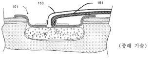
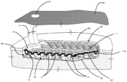
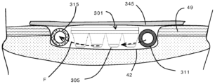
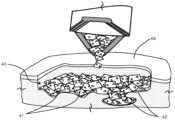
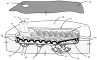
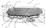
일부 상처 치료 시스템은 치유를 돕기 위해 치료 유체를 상처에 전달하는 것을 수반한다. 도 1 내지 도 3은 일부 종래 기술 시스템(101)을 도시한다. 치료 유체는 전형적으로, 유체 공급 도관(151)을 통해 양압 하에서(대기압 초과에서) 상처로 전달된다. 양압은 치료 유체로 상처 부위의 완전한 포화를 보장하지만, 상처 부위가 주변 또는 양압 레벨로 남아 있게 한다. 음압은 치료 유체의 적용 후에 적용되어, 밀봉된 상처 환경의 자유 부피를 감소시키고 유체 제거 도관(153)을 통해 상처 부위로부터 멀리 치료 유체 및 삼출물을 끌어당길 수 있다. 상처 치료 부위에 적용되는 양압은, 전형적으로 상처주변부와 커버 드레싱 사이에서, 상처 드레싱으로부터 누출을 유도하는 것과 같은 의도되지 않은 결과를 가질 수 있다.Some wound care systems involve delivering therapeutic fluids to a wound to aid healing. 1-3 illustrate some
본 발명의 적어도 바람직한 실시 형태의 목적은 상기의 단점들 중 하나 이상을 해결하고/하거나 적어도, 유용한 대안을 공중에 제공하는 것이다.The objective of at least a preferred embodiment of the present invention is to solve one or more of the above drawbacks and/or at least to provide the public with a useful alternative.
특허 명세서, 기타 외부 문서, 또는 기타 정보 자료를 참조한 본 명세서에서, 이는 일반적으로 본 발명의 특징을 논의하기 위한 배경을 제공하기 위한 것이다. 달리 구체적으로 언급하지 않는 한, 그러한 외부 문서 또는 정보 자료에 대한 언급은 그 어떤 재판관할에서도 그러한 문서 또는 정보 자료가 선행 기술이라거나 또는 해당 기술 분야의 보편적인 일반 지식의 일부를 형성하는 것이라고 인정하는 것으로 해석되어서는 안 된다.Where reference is made herein to patent specifications, other external documents, or other information sources, it is generally intended to provide a background for discussing the features of the invention. Unless specifically stated otherwise, any reference to such external document or information material does not constitute a finding in any jurisdiction that such document or information material is prior art or forms part of the general general knowledge in the art. It should not be interpreted as
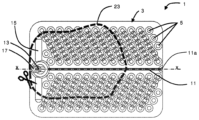
제1 태양에 따르면, 본 명세서에 기술된 본 발명은 광범위하게는, 음압 상처 치료법에서 사용하기 위한 상처 인터페이스 디바이스에 있으며, 디바이스는 복수의 스페이서를 갖는 가요성 몸체 - 스페이서는 상처 표면과 디바이스 몸체의 상처 대향 표면 사이에 치료 공간을 한정하도록 구성됨 -; 상처 부위로의 유체의 점적주입을 위한 입구; 및 치료 공간으로부터의 유체의 제거를 위한 출구를 포함한다.According to a first aspect, the invention described herein broadly resides in a wound interface device for use in negative pressure wound therapy, the device comprising a flexible body having a plurality of spacers, wherein the spacers are positioned at the surface of the wound and the body of the device. Configured to define a treatment space between opposing surfaces of the wound -; an inlet for instillation of fluid into the wound site; and an outlet for removal of fluid from the treatment space.
일 실시 형태에서, 입구는 디바이스의 제1 단부에 인접한 영역으로 유체를 전달하도록 구성되고, 출구는 디바이스의 제2, 반대편 단부에 인접한 영역으로부터 유체를 제거하도록 구성된다.In one embodiment, the inlet is configured to deliver fluid to an area adjacent a first end of the device, and the outlet is configured to remove fluid from an area adjacent to a second, opposite end of the device.
일 실시 형태에서, 스페이서는 디바이스의 제1 단부와 제2 단부 사이에 다수의 채널을 한정한다.In one embodiment, the spacer defines multiple channels between the first and second ends of the device.
일 실시 형태에서, 채널은 디바이스의 제1 단부와 제2 단부 사이에서 상처 표면을 가로질러 측방향으로 유체를 지향시키도록 형상화된다.In one embodiment, the channel is shaped to direct fluid laterally across the wound surface between the first and second ends of the device.
일 실시 형태에서, 채널은 브리지, 물결 모양(corrugation), 또는 셰브론으로 형상화된다.In one embodiment, the channels are shaped as bridges, corrugations, or chevrons.
일 실시 형태에서, 스페이서는 치료 공간에 대한 음압의 적용 하에서 스페이서 및/또는 치료 공간의 붕괴를 방지하도록 형상화되고 분포된다.In one embodiment, the spacer is shaped and distributed to prevent collapse of the spacer and/or the treatment space under application of negative pressure to the treatment space.
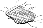
일 실시 형태에서, 스페이서는 구근형 또는 대체적으로 반구형이다. 스페이서는 스페이서의 편향 지점을 한정하기 위한 언더컷을 포함할 수 있다.In one embodiment, the spacer is bulbous or generally hemispherical. The spacer may include an undercut to define the spacer's deflection point.
각각의 스페이서의 벽은 균일할 수 있거나, 또는 스페이서의 상이한 부분에서 달라질 수 있다. 더 얇은 벽 영역이 스페이서의 편향 지점을 한정하기 위한 언더컷 영역을 생성하도록 활용될 수 있다.The walls of each spacer may be uniform, or may vary in different parts of the spacer. Thinner wall areas can be utilized to create an undercut area to define the deflection point of the spacer.
일 실시 형태에서, 스페이서는 형상화된 돌출부를 포함한다.In one embodiment, the spacer includes shaped protrusions.
일 실시 형태에서, 스페이서는 각각 볼록한 상처 접촉 표면을 포함한다. 대안적인 실시 형태에서, 스페이서는 오목한 상처 대향 표면을 포함할 수 있다.In one embodiment, the spacers each include a convex wound contact surface. In alternative embodiments, the spacer may include a concave wound facing surface.
일 실시 형태에서, 스페이서는 세포외 기질(extracellular matrix, ECM) 또는 세포외 기질(ECM) 재료가 들어올려지는 것을 방지하도록 이격된다.In one embodiment, the spacers are spaced apart to prevent the extracellular matrix (ECM) or extracellular matrix (ECM) material from lifting.
일 실시 형태에서, 몸체는 다양한 상처 표면의 윤곽에 순응하도록 휘는 순응성, 가요성 부재를 포함한다.In one embodiment, the body includes a conformable, flexible member that bends to conform to the contours of various wound surfaces.
일 실시 형태에서, 상처 인터페이스 디바이스는 다양한 상처의 주연부 내에 끼워맞춤되도록 트리밍가능하다. 일부 실시 형태에서, 몸체는 디바이스의 인열이 그의 형상을 맞춤화할 수 있게 하기 위한 천공을 스페이서들 사이에 포함할 수 있다.In one embodiment, the wound interface device is trimmable to fit within the perimeter of various wounds. In some embodiments, the body may include perforations between spacers to allow tearing of the device to customize its shape.
일 실시 형태에서, 상처 가요성 부재는 순응성이다. 가요성 부재는 일정 벽 두께를 갖는다.In one embodiment, the wound flexible member is conformable. The flexible member has a constant wall thickness.
일 실시 형태에서, 입구는 유체 공급원에 결합하기 위한 입구 포트; 및 디바이스의 제1 단부로 유체를 전달하도록 구성된, 입구 포트와 유체 연통하는 입구 채널을 포함한다.In one embodiment, the inlet includes an inlet port for coupling to a fluid source; and an inlet channel in fluid communication with the inlet port, configured to deliver fluid to the first end of the device.
일 실시 형태에서, 출구는 음압원에 결합하기 위한 출구 포트; 및 디바이스의 제2 단부로부터 유체를 제거하도록 구성된, 출구 포트와 유체 연통하는 출구 채널을 포함한다.In one embodiment, the outlet includes an outlet port for coupling to a negative pressure source; and an outlet channel in fluid communication with the outlet port, configured to remove fluid from the second end of the device.
일 실시 형태에서, 입구 채널은 제1 방향으로 연장되고, 출구 채널은 제1 방향에 수직하는 제2 방향으로 연장된다. 예를 들어, 출구 채널은 디바이스의 횡방향으로 연장된다. 입구 채널은 디바이스의 종방향으로 연장될 수 있다.In one embodiment, the inlet channel extends in a first direction and the outlet channel extends in a second direction perpendicular to the first direction. For example, the outlet channel extends transversely of the device. The inlet channel may extend longitudinally of the device.
일 실시 형태에서, 입구 포트 및 출구 포트는 디바이스 몸체의 반대편 측부로부터 상처 대향 측부로 연장되는 성형된 부재 상에 제공된다.In one embodiment, the inlet port and outlet port are provided on a molded member extending from opposite sides of the device body to the side opposite the wound.
일 실시 형태에서, 입구 포트는 출구 포트에 대해 종방향이다. 다른 실시 형태에서, 입구 포트는 출구 포트에 대해 횡방향이다.In one embodiment, the inlet port is longitudinal relative to the outlet port. In another embodiment, the inlet port is transverse to the outlet port.
일 실시 형태에서, 출구 채널은 치료 공간으로부터 출구 채널 내로의 유체의 침입을 허용하도록 위치된 세장형 슬롯을 포함한다.In one embodiment, the outlet channel includes an elongated slot positioned to allow ingress of fluid from the treatment space into the outlet channel.
일 실시 형태에서, 슬롯은 디바이스의 횡방향으로 연장된다.In one embodiment, the slot extends transversely of the device.
일 실시 형태에서, 출구 채널은 치료 공간으로부터 출구 채널 내로의 유체의 침입을 허용하도록 복수의 개구부를 포함한다.In one embodiment, the outlet channel includes a plurality of openings to allow entry of fluid from the treatment space into the outlet channel.
출구 채널 개구부는 디바이스의 몸체의 평면에 실질적으로 수직하는 슬릿을 포함할 수 있다.The outlet channel opening may include a slit substantially perpendicular to the plane of the body of the device.
일 실시 형태에서, 상처 인터페이스 디바이스는 상처의 폭에 걸쳐 압력을 적용한다. 슬롯의 폭은 차단 물질이 출구 포트에 들어가는 것을 방지할 수 있다.In one embodiment, the wound interface device applies pressure across the width of the wound. The width of the slot can prevent blocking material from entering the outlet port.
일 실시 형태에서, 몸체는 탄성중합체 재료로 형성된다.In one embodiment, the body is formed from an elastomeric material.
일 실시 형태에서, 몸체는 실리콘으로 형성된다.In one embodiment, the body is formed of silicone.
일 실시 형태에서, 탄성중합체 재료는 열가소성 물질이다.In one embodiment, the elastomeric material is a thermoplastic.
일 실시 형태에서, 탄성중합체 재료에는 코팅이 제공된다.In one embodiment, the elastomeric material is provided with a coating.
일 실시 형태에서, 몸체는 액체 및 공기 불침투성이다.In one embodiment, the body is impermeable to liquid and air.
일 실시 형태에서, 몸체는 그를 통한 어떠한 개구부도 갖지 않는다.In one embodiment, the body does not have any openings therethrough.
제2 태양에 따르면, 본 명세서에 기술된 본 발명은 광범위하게는, 상처에 음압을 적용하기 위한 상처 드레싱에 있으며, 드레싱은, 본 발명의 제1 태양에 따른 상처 인터페이스 디바이스; 및 액체 불침투성 폐색 외부 층을 포함한다.According to a second aspect, the invention described herein broadly resides in a wound dressing for applying negative pressure to a wound, the dressing comprising: a wound interface device according to the first aspect of the invention; and a liquid impermeable occlusive outer layer.
일 실시 형태에서, 상처 드레싱은 상처 인터페이스 디바이스와 상처 표면 사이에 배치하기 위한 생체흡수성 층을 추가로 포함한다.In one embodiment, the wound dressing further includes a bioabsorbable layer for placement between the wound interface device and the wound surface.
일 실시 형태에서, 생체흡수성 층은 상처로부터 포팅 층(porting layer)으로의 유체 유동을 가능하게 하기 위한 복수의 개구부를 포함한다.In one embodiment, the bioresorbable layer includes a plurality of openings to allow fluid flow from the wound to the porting layer.
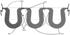
일 실시 형태에서, 개구부 또는 슬릿은 실질적으로 X-형상, Y-형상, C-형상, U-형상, 또는 V-형상이다.In one embodiment, the opening or slit is substantially X-shaped, Y-shaped, C-shaped, U-shaped, or V-shaped.
일 실시 형태에서, 생체흡수성 층은 생체흡수성 재료의 다수의 작은 조각을 포함한다.In one embodiment, the bioabsorbable layer includes multiple small pieces of bioabsorbable material.
일 실시 형태에서, 생체흡수성 시트 층은 세포외 기질(ECM)을 포함한다.In one embodiment, the bioresorbable sheet layer includes extracellular matrix (ECM).
일 실시 형태에서, 상처 드레싱은 입구 포트 및 출구 포트를 포함하고, 상처로의 유체의 공급을 위해 입구 포트에 결합하기 위한 입구 도관 및 상처로의 음압의 적용을 위한 출구 도관을 포함한다.In one embodiment, the wound dressing includes an inlet port and an outlet port, an inlet conduit for coupling to the inlet port for supply of fluid to the wound and an outlet conduit for application of negative pressure to the wound.
일 실시 형태에서, 입구 도관 및 출구 도관은 이중 루멘 도관에 의해 제공된다.In one embodiment, the inlet conduit and outlet conduit are provided by double lumen conduits.
일 실시 형태에서, 이중 루멘 도관은 드레싱에 음압을 적용하기 위해 출구에 결합되는 1차 도관, 및 드레싱에 유체를 도입하기 위해 그리고/또는 압력 측정을 용이하게 하기 위해 입구에 결합되는 2차 도관을 포함한다.In one embodiment, the dual lumen conduit has a primary conduit coupled to the outlet for applying negative pressure to the dressing, and a secondary conduit coupled to the inlet for introducing fluid to the dressing and/or to facilitate pressure measurements. Includes.
일 실시 형태에서, 폐색 층은 접착제 표면을 포함하는 폴리우레탄 시트를 포함한다.In one embodiment, the occlusive layer includes a polyurethane sheet comprising an adhesive surface.
일 실시 형태에서, 상처 드레싱은 상처를 둘러싸기 위한 성형가능한 접착제 밀봉부를 포함하고, 밀봉부는 부틸 고무, 충전제, 및 점착성 수지를 포함한다.In one embodiment, the wound dressing includes a moldable adhesive seal to enclose a wound, the seal comprising butyl rubber, filler, and an adhesive resin.
일 실시 형태에서, 밀봉부는 환자의 피부에 대해 제거가능하고 재밀봉가능하다.In one embodiment, the seal is removable and resealable to the patient's skin.
일 실시 형태에서, 밀봉부는 비-경화성이다.In one embodiment, the seal is non-curable.
일 실시 형태에서, 밀봉부는 부틸 고무, 충전제, 및 점착성 수지를 포함한다.In one embodiment, the seal includes butyl rubber, filler, and adhesive resin.
제3 태양에 따르면, 본 명세서에 기술된 본 발명은 광범위하게는, 본 발명의 제1 태양에 따른 상처 인터페이스 디바이스; 및 액체 불침투성 폐색 외부 층을 포함하는 부품 키트에 있다.According to a third aspect, the invention described herein broadly includes a wound interface device according to the first aspect of the invention; and a liquid impermeable occlusive outer layer.
일 실시 형태에서, 부품 키트는 접착제 밀봉부를 추가로 포함한다.In one embodiment, the kit of parts further includes an adhesive seal.
일 실시 형태에서, 제1 제거가능한 이형 시트가 접착제 밀봉부의 일 측부에 접착되고, 제2 제거가능한 이형 시트가 접착제 밀봉부의 제2 측부에 접착되고, 여기서 제2 제거가능한 이형 시트는 신장가능하다.In one embodiment, a first removable release sheet is adhered to one side of the adhesive seal and a second removable release sheet is adhered to a second side of the adhesive seal, wherein the second removable release sheet is extensible.
부품 키트는 상처 인터페이스 디바이스의 입구 포트 및 출구 포트에 결합하기 위한 커넥터를 포함할 수 있다.The kit of parts may include connectors for coupling to the inlet port and outlet port of the wound interface device.
일 실시 형태에서, 커넥터는 2-부분 커넥터이다. 커넥터는 입구 및 출구 포트 인터페이싱 부분, 및 인터페이싱 부분을 제자리에 유지하기 위한 칼라를 포함할 수 있다.In one embodiment, the connector is a two-part connector. The connector may include inlet and outlet port interfacing portions, and a collar to retain the interfacing portions in place.
일 실시 형태에서, 상처 인터페이스 디바이스는 모따기된(chamfered) 표면을 갖는 보스(boss)를 포함하고, 커넥터는 보스의 모따기된 표면과 밀봉하여 맞물리기 위한 상보적 모따기된 표면을 포함한다.In one embodiment, the wound interface device includes a boss having a chamfered surface, and the connector includes a complementary chamfered surface for sealingly engaging with the chamfered surface of the boss.
일 실시 형태에서, 커넥터 및/또는 디바이스는 디바이스에 대해 커넥터를 정확하게 배향하는 것을 보조하기 위한 위치결정 특징부를 포함한다. 위치결정 특징부는 커넥터와 맞물리기 위한 보유 특징부를 포함할 수 있다. 일부 실시 형태에서, 위치결정 특징부는 디바이스 몸체의 상단 표면으로부터 연장되는 탭을 포함한다.In one embodiment, the connector and/or device includes positioning features to assist in accurately orienting the connector relative to the device. The positioning features may include retaining features for engaging the connector. In some embodiments, the positioning feature includes a tab extending from the top surface of the device body.
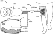
제4 태양에 따르면, 본 명세서에 기술된 본 발명은 광범위하게는, 본 발명의 제2 태양에 따른 상처 드레싱, 및 디바이스 출구에 결합되고 상처 드레싱에 음압을 적용하도록 구성된 펌프를 포함하는 상처 치료 시스템에 있다.According to a fourth aspect, the invention described herein broadly refers to a wound care system comprising a wound dressing according to the second aspect of the invention, and a pump coupled to the device outlet and configured to apply negative pressure to the wound dressing. It is in
시스템은 상처에 위치된 상처 치료 디바이스로의 연결을 위한 유체 입력 및 유체 출력을 포함한다. 상처 치료 디바이스는 전술된 바와 같을 수 있다. 유체 입력은 상처 치료 디바이스의 상류 측에 유체적으로 연결되도록 적응되고, 유체 출력은 상처 치료 디바이스의 하류 측에 유체적으로 연결되도록 적응된다.The system includes a fluid input and fluid output for connection to a wound care device located at the wound. The wound care device may be as described above. The fluid input is adapted to be fluidly coupled to an upstream side of the wound care device, and the fluid output is adapted to be fluidly coupled to a downstream side of the wound care device.
일 실시 형태에서, 폐색 층은 환자의 피부에 그리고 상처 치료 디바이스 위에 접착된다.In one embodiment, the occlusive layer is adhered to the patient's skin and over the wound care device.
일 실시 형태에서, 상처 치료 시스템은 드레싱으로부터 제거된 삼출물을 수집하기 위한 저장소를 추가로 포함한다.In one embodiment, the wound care system further includes a reservoir for collecting exudate removed from the dressing.
일 실시 형태에서, 상처 치료 시스템은 상처에 제공하기 위한 치료 유체를 저장하기 위한 저장소를 추가로 포함한다.In one embodiment, the wound care system further includes a reservoir for storing treatment fluid for provision to the wound.
일 실시 형태에서, 펌프는 이중 루멘 도관에 의해 상처 드레싱에 결합된다.In one embodiment, the pump is coupled to the wound dressing by a dual lumen conduit.
일 실시 형태에서, 상처 치료 시스템은 상처 치료 디바이스 입구의 상류의 공기 입구 밸브; 공기 입구 밸브를 개방 위치와 폐쇄 위치 사이에서 구동하기 위한 액추에이터; 액추에이터와 통신하는 제어기; 및 공기 입구 밸브 및 펌프를 동작시키기 위해 펌프를 구동하는 모터를 추가로 포함하고, 제어기는, i) 공기 입구 밸브를 개방하고 펌프를 동작시켜 상처 치료 디바이스에서 제1 진공 압력을 유지하고 공기를 상처 치료 디바이스 내로 도입하도록; 그리고 ii) 공기 입구 밸브를 폐쇄하고 펌프를 동작시켜 상처 치료 디바이스에서 제2 진공 압력을 유지하고 공기 및 유체를 상처 치료 디바이스로부터 제거하도록 구성되고; 제1 진공 압력은 제2 진공 압력 이하이다.In one embodiment, the wound care system includes an air inlet valve upstream of the wound care device inlet; an actuator for driving the air inlet valve between open and closed positions; A controller that communicates with the actuator; and a motor that drives the pump to operate the air inlet valve and the pump, wherein the controller: i) opens the air inlet valve and operates the pump to maintain a first vacuum pressure in the wound care device and supply air to the wound; to introduce into a treatment device; and ii) closing the air inlet valve and operating the pump to maintain a second vacuum pressure in the wound care device and remove air and fluid from the wound care device; The first vacuum pressure is less than or equal to the second vacuum pressure.
일 실시 형태에서, 제어기는 공기 밸브가 개방되고 폐쇄될 때 상처 치료 디바이스에서 음압 환경을 연속적으로 유지하기 위해 펌프를 동작시키도록 구성된다.In one embodiment, the controller is configured to operate the pump to continuously maintain a negative pressure environment in the wound care device as the air valve opens and closes.
일 실시 형태에서, 제1 및 제2 진공 압력은 효과적인 음압 상처 치료법(negative pressure wound therapy)을 제공한다.In one embodiment, the first and second vacuum pressures provide effective negative pressure wound therapy.
일 실시 형태에서, 제어기는 단계 i) 및 단계 ii)를 반복하여 공기 입구 밸브를 개방 위치와 폐쇄 위치 사이에서 사이클링하도록 구성된다.In one embodiment, the controller is configured to cycle the air inlet valve between open and closed positions by repeating steps i) and step ii).
일 실시 형태에서, 제어기는 공기 입구 밸브가 개방될 때 실질적으로 일정한 제1 진공 압력을 유지하기 위해 펌프를 동작시키도록 구성된다.In one embodiment, the controller is configured to operate the pump to maintain the first vacuum pressure substantially constant when the air inlet valve is opened.
일 실시 형태에서, 제어기는 공기 입구 밸브가 폐쇄될 때 실질적으로 일정한 제2 진공 압력을 유지하기 위해 펌프를 동작시키도록 구성된다.In one embodiment, the controller is configured to operate the pump to maintain the second vacuum pressure substantially constant when the air inlet valve is closed.
일 실시 형태에서, 제어기는, 단계 (i)에서, 시스템이 치료 디바이스에 걸쳐 0 또는 일정한 압력 차이를 갖는 평형 상태에 있도록 하기 위해, 공기 입구 밸브가 개방된 상태에서, 펌프를 동작시키도록 구성되고; 단계 (ii)에서, 시스템이 치료 디바이스에 걸쳐 0 또는 일정한 압력 차이를 갖는 평형 상태에 있도록 하기 위해, 공기 입구 밸브가 폐쇄된 상태에서 펌프를 동작시키도록 구성된다.In one embodiment, the controller is configured to, in step (i), operate the pump with the air inlet valve open such that the system is in equilibrium with a zero or constant pressure difference across the treatment device. ; In step (ii), the pump is configured to operate with the air inlet valve closed so that the system is in equilibrium with a zero or constant pressure difference across the treatment device.
일 실시 형태에서, 제어기는 상처 치료 디바이스로부터 유체 유동에 혼입된 공기의 버블 또는 슬러그를 포함하는 버블 유동 또는 슬러그 유동을 생성하는 공기의 유량을 시스템 내로 도입하기 위해 공기 입구 밸브를 개방된 상태와 폐쇄된 상태 사이에서 동작시키도록 구성된다.In one embodiment, the controller opens and closes an air inlet valve to introduce a flow rate of air into the system that creates a bubble flow or slug flow comprising bubbles or slugs of air entrained in the fluid flow from the wound care device. It is configured to operate between the specified states.
일 실시 형태에서, 제어기는 상처에서 유체의 밀도를 감소시켜 중력에 대항하여 상처로부터 유체를 들어올리기 위해 공기 입구 밸브를 개방된 상태와 폐쇄된 상태 사이에서 동작시키도록 구성된다.In one embodiment, the controller is configured to operate the air inlet valve between an open and closed state to lift fluid from the wound against gravity by reducing the density of fluid in the wound.
일 실시 형태에서, 제어기는 공기 입구 밸브를 주기적으로 개방하고 폐쇄하도록 구성된다.In one embodiment, the controller is configured to periodically open and close the air inlet valve.
일 실시 형태에서, 단계 i)에서, 제어기는 미리결정된 기간 동안 공기 입구 밸브를 개방하도록 구성된다.In one embodiment, in step i), the controller is configured to open the air inlet valve for a predetermined period of time.
일 실시 형태에서, 단계 i)에서, 제어기는 적어도 10초 동안 공기 입구 밸브를 개방하도록 구성된다.In one embodiment, in step i), the controller is configured to open the air inlet valve for at least 10 seconds.
일 실시 형태에서, 단계 ii)에서, 제어기는 미리결정된 기간 동안 공기 입구 밸브를 폐쇄하도록 구성된다. 일 실시 형태에서, 단계 i)에서, 제어기는 적어도 10초 동안 공기 입구 밸브를 개방하도록 구성된다.In one embodiment, in step ii), the controller is configured to close the air inlet valve for a predetermined period of time. In one embodiment, in step i), the controller is configured to open the air inlet valve for at least 10 seconds.
일 실시 형태에서, 공기 입구 밸브는 사이클 피치의 적어도 10%, 또는 사이클 피치의 적어도 20%, 또는 사이클 피치의 적어도 30%, 또는 사이클 피치의 40%, 또는 사이클 피치의 적어도 50% 동안 개방된다.In one embodiment, the air inlet valve is open for at least 10% of the cycle pitch, or at least 20% of the cycle pitch, or at least 30% of the cycle pitch, or 40% of the cycle pitch, or at least 50% of the cycle pitch.
일 실시 형태에서, 단계 i)에서, 공기 입구 밸브는 시스템을 통해 전달되는 공기의 부피가 시스템의 총 부피의 적어도 상당한 부분이 되도록 충분한 기간 동안 개방된다.In one embodiment, in step i), the air inlet valve is opened for a sufficient period of time such that the volume of air delivered through the system is at least a significant portion of the total volume of the system.
일 실시 형태에서, 단계 (i)에서, 공기 입구 밸브는 시스템으로 전달되는 공기의 부피가 시스템의 총 부피의 적어도 50% 또는 적어도 100%가 되도록 충분한 기간 동안 개방된다.In one embodiment, in step (i), the air inlet valve is opened for a sufficient period of time such that the volume of air delivered to the system is at least 50% or at least 100% of the total volume of the system.
일 실시 형태에서, 제1 진공 압력은 제2 진공 압력의 약 30% 내지 100%이다.In one embodiment, the first vacuum pressure is about 30% to 100% of the second vacuum pressure.
일 실시 형태에서, 제1 진공 압력은 약 30 내지 100 mmHg, 바람직하게는 약 30 내지 70 mmHg이다.In one embodiment, the first vacuum pressure is about 30 to 100 mmHg, preferably about 30 to 70 mmHg.
일 실시 형태에서, 제2 진공 압력은 약 100 내지 150 mmHg이다.In one embodiment, the second vacuum pressure is about 100 to 150 mmHg.
일 실시 형태에서, 제1 진공 압력은 제2 압력보다 약 10 내지 125 mmHg 더 작은, 예를 들어 약 10 내지 125 mmHg이다.In one embodiment, the first vacuum pressure is about 10 to 125 mmHg less than the second pressure, for example about 10 to 125 mmHg.
일 실시 형태에서, 단계 (i)에서, 제어기는 진공 압력 임계치를 달성하기 위해 펌프를 동작시키도록 구성된다.In one embodiment, in step (i), the controller is configured to operate the pump to achieve the vacuum pressure threshold.
일 실시 형태에서, 단계 (ii)에서, 제어기는 진공 압력 임계치를 달성하기 위해 펌프를 동작시키도록 구성된다.In one embodiment, in step (ii), the controller is configured to operate the pump to achieve the vacuum pressure threshold.
일 실시 형태에서, 시스템은 상처 치료 디바이스의 하류에 위치되고 제어기와 통신하는 하류 압력 센서를 포함하고, 제어기는 단계 i)에서, 하류 압력 센서에 의해 감지된 압력에 기초하여 진공 압력 임계치를 달성하기 위해 펌프를 동작시키도록 구성된다.In one embodiment, the system includes a downstream pressure sensor located downstream of the wound care device and in communication with a controller, wherein the controller is configured to, in step i), achieve a vacuum pressure threshold based on the pressure sensed by the downstream pressure sensor. It is configured to operate the pump.
일 실시 형태에서, 시스템은 상처 치료 디바이스의 상류에 위치되고 제어기와 통신하는 상류 압력 센서를 포함하고, 제어기는 단계 ii)에서, 상류 압력 센서에 의해 감지된 압력에 기초하여 진공 압력 임계치를 달성하기 위해 펌프를 동작시키도록 구성된다.In one embodiment, the system includes an upstream pressure sensor located upstream of the wound care device and in communication with a controller, wherein the controller is configured to, in step ii), achieve a vacuum pressure threshold based on the pressure sensed by the upstream pressure sensor. It is configured to operate the pump.
일 실시 형태에서, 시스템은 상처 치료 디바이스의 상류에 위치되고 제어기와 통신하는 상류 압력 센서, 및 상처 치료 디바이스의 하류에 위치되고 제어기와 통신하는 하류 압력 센서를 포함하고, 제어기는 단계 i)에서, 하류 압력 센서에 의해 감지된 압력에 기초하여 제1 진공 압력 임계치를 달성하기 위해 펌프를 동작시키도록; 그리고 단계 ii)에서, 상류 압력 센서에 의해 감지된 압력에 기초하여 제2 진공 압력 임계치를 달성하기 위해 펌프를 동작시키도록 구성된다.In one embodiment, the system includes an upstream pressure sensor located upstream of the wound care device and in communication with a controller, and a downstream pressure sensor located downstream of the wound care device and in communication with the controller, wherein the controller in step i): operate the pump to achieve a first vacuum pressure threshold based on the pressure sensed by the downstream pressure sensor; and in step ii), operate the pump to achieve a second vacuum pressure threshold based on the pressure sensed by the upstream pressure sensor.
일 실시 형태에서, 제1 진공 압력 임계치는 제2 진공 압력 임계치 이하이다.In one embodiment, the first vacuum pressure threshold is less than or equal to the second vacuum pressure threshold.
일 실시 형태에서, 시스템은 입구 제한부를 포함하고, 상류 압력 센서는 공기 입구 밸브가 개방될 때 상류 압력 센서가 주변 압력을 측정하도록 입구 제한부의 상류에 위치된다.In one embodiment, the system includes an inlet restrictor, and an upstream pressure sensor is positioned upstream of the inlet restrictor such that the upstream pressure sensor measures ambient pressure when the air inlet valve is opened.
일 실시 형태에서, 시스템은 상처로부터 제거된 유체를 수집하기 위한 저장소를 포함하고, 저장소는 펌프의 하류에 위치되어, 상처로부터 제거된 유체가 펌프를 통해 저장소로 전달되도록 한다.In one embodiment, the system includes a reservoir for collecting fluid removed from the wound, and the reservoir is located downstream of a pump, such that fluid removed from the wound is delivered to the reservoir via the pump.
일 실시 형태에서, 저장소는 가요성 백을 포함한다.In one embodiment, the reservoir includes a flexible bag.
일 실시 형태에서, 저장소는 저장소를 주변 분위기로 통기하기 위한 통기구를 포함한다.In one embodiment, the reservoir includes a vent for venting the reservoir to the surrounding atmosphere.
일 실시 형태에서, 시스템은 상처를 덮는 폐색 커버 층;In one embodiment, the system includes an occlusive cover layer covering a wound;
유체 출구와 유체 연통하고, 하나 이상의 공급용 도관 출구를 갖는 유체 공급용 도관;a fluid supply conduit in fluid communication with the fluid outlet, the fluid supply conduit having at least one supply conduit outlet;
유체 입구와 유체 연통하고, 하나 이상의 제거용 도관 입구를 갖는 유체 제거용 도관을 포함한다.and a fluid removal conduit in fluid communication with the fluid inlet, the fluid removal conduit having one or more removal conduit inlets.
일 실시 형태에서, 시스템은 치료 유체의 공급부를 연결하기 위해 유체 출구의 상류에 치료 유체 입구를 포함한다.In one embodiment, the system includes a treatment fluid inlet upstream of the fluid outlet to connect a supply of treatment fluid.
일 실시 형태에서, 시스템은, 단계 i)에서, 제1 진공 압력에 의해 상처 치료 디바이스로 공기를 도입함으로써 상처 치료 디바이스로의 치료 유체의 도입이 방지되거나 감소되고, 단계 ii)에서, 치료 유체가 제2 진공 압력에 의해 상처 치료 디바이스로 끌어당겨지도록 구성된다.In one embodiment, the system is configured to prevent or reduce the introduction of treatment fluid into the wound treatment device by introducing air into the wound treatment device by means of a first vacuum pressure, in step i), and wherein in step ii), the treatment fluid is It is configured to be pulled into the wound treatment device by a second vacuum pressure.
일 실시 형태에서, 시스템은,In one embodiment, the system:
치료 유체 입구와 유체 출구 사이의 치료 유체 밸브, 및 a treatment fluid valve between a treatment fluid inlet and a fluid outlet, and
공기 입구 밸브를 개방 위치와 폐쇄 위치 사이에서 구동하기 위한 액추에이터를 포함하고, 제어기는 유체 입구 밸브 액추에이터와 통신하고, 제어기는 유체 공급 상태에서, an actuator for actuating the air inlet valve between an open position and a closed position, wherein the controller is in communication with the fluid inlet valve actuator, wherein in the fluid supply state, the controller:
iii) 유체 입구 밸브를 개방하고 펌프를 동작시켜 상처 치료 디바이스에서 진공 압력을 유지하고 치료 유체를 상처 치료 디바이스 내로 도입하도록; 그리고 iii) open the fluid inlet valve and operate the pump to maintain vacuum pressure in the wound treatment device and introduce treatment fluid into the wound treatment device; and
iv) 유체 입구 밸브를 폐쇄하고 펌프를 동작시켜 상처 치료 디바이스에서 진공 압력을 유지하고 상처 치료 디바이스로부터 유체를 제거하도록 구성된다. iv) Close the fluid inlet valve and operate the pump to maintain vacuum pressure in the wound care device and remove fluid from the wound care device.
일 실시 형태에서, 제어기는 유체 입구 밸브가 개방되고 폐쇄될 때 상처 치료 디바이스에서 음압 환경을 연속적으로 유지하기 위해 펌프를 동작시키도록 구성된다.In one embodiment, the controller is configured to operate the pump to continuously maintain a negative pressure environment in the wound care device as the fluid inlet valve opens and closes.
일 실시 형태에서, 제어기는, 단계 (iii)에서, 펌프를 동작시켜, 상처 치료 디바이스에서 제3 진공 압력을 생성하도록; 그리고 단계 (iv)에서, 펌프를 동작시켜, 상처 치료 디바이스에서 제4 진공 압력을 생성하도록 구성되며, 여기서 제3 진공 압력은 제4 진공 압력 이하이다.In one embodiment, the controller, in step (iii), operates the pump to create a third vacuum pressure in the wound care device; and in step (iv), operate the pump to generate a fourth vacuum pressure in the wound treatment device, wherein the third vacuum pressure is less than or equal to the fourth vacuum pressure.
일 실시 형태에서, 제3 진공 압력은 제1 진공 압력과 동일하거나 유사하고, 제4 진공 압력은 제2 진공 압력과 동일하거나 유사하다.In one embodiment, the third vacuum pressure is the same or similar to the first vacuum pressure and the fourth vacuum pressure is the same or similar to the second vacuum pressure.
일 실시 형태에서, 제3 및 제4 진공 압력은 효과적인 음압 상처 치료법을 제공한다.In one embodiment, the third and fourth vacuum pressures provide effective negative pressure wound therapy.
일 실시 형태에서, 유체 입구 밸브를 폐쇄하고 펌프를 동작시켜 상처에서 진공 압력을 생성한 후에, 제어기는,In one embodiment, after closing the fluid inlet valve and operating the pump to create vacuum pressure in the wound, the controller:
(v) 상처로부터 치료 유체를 플러싱하되, (v) flushing therapeutic fluid from the wound,
(v)(a) 공기 입구 밸브를 개방하고 펌프를 동작시켜 상처 치료 디바이스에서 진공 압력(예컨대, 제1 진공 압력)을 유지하고 공기를 상처 치료 디바이스 내로 도입하는 것, 및 (v)(a) opening the air inlet valve and operating the pump to maintain a vacuum pressure (e.g., a first vacuum pressure) in the wound care device and introduce air into the wound care device, and
(v)(a) 공기 입구 밸브를 폐쇄하고 펌프를 동작시켜 상처 치료 디바이스에서 진공 압력(예컨대, 제2 진공 압력)을 유지하고 상처 치료 디바이스로부터 공기를 제거하는 것에 의해 플러싱하도록 구성된다. (v)(a) configured to flush by closing the air inlet valve and operating the pump to maintain a vacuum pressure (e.g., a second vacuum pressure) in the wound care device and to remove air from the wound care device.
일 실시 형태에서, 단계 (v)에서, 제어기는, 상처로부터 치료 유체를 제거하기 위해 단계 (v)(a) 및 (v)(b)를 미리결정된 횟수(예를 들어, 3회)만큼 반복하도록 구성된다.In one embodiment, in step (v), the controller repeats steps (v)(a) and (v)(b) a predetermined number of times (e.g., three times) to remove treatment fluid from the wound. It is configured to do so.
일 실시 형태에서, 유체 치료 상태에서, 제어기는 단계 (iii) 내지 단계 (v)를 미리결정된 횟수만큼 반복하도록 구성된다.In one embodiment, in the fluid treatment state, the controller is configured to repeat steps (iii) through (v) a predetermined number of times.
일 실시 형태에서, 제어기는, 단계 (iv)에서, 유체 입구 밸브를 폐쇄하고, 미리결정된 기간 동안 기다리고, 펌프를 동작시켜 상처 치료 디바이스에서 진공 압력을 생성하고 상처 치료 디바이스로부터 유체를 제거하도록 구성된다.In one embodiment, the controller is configured to, in step (iv), close the fluid inlet valve, wait a predetermined period of time, and operate the pump to create a vacuum pressure in the wound care device and remove fluid from the wound care device. .
일 실시 형태에서, 제어기는 유체 공급 상태를 주기적으로 활성화하도록 구성된다.In one embodiment, the controller is configured to periodically activate the fluid supply state.
일 실시 형태에서, 유체 공급 상태를 활성화하는 사이의 기간은 공기 입구 밸브의 사이클 시간보다 훨씬 더 크다.In one embodiment, the period between activating fluid supply conditions is significantly greater than the cycle time of the air inlet valve.
일 실시 형태에서, 시스템은 제어기와 통신하는 상류 압력 센서 및/또는 하류 압력 센서를 포함하고, 단계 (iii)에서, 제어기는 펌프를 동작시켜서, 상류 및/또는 하류 압력 센서에 의해 감지된 압력에 기초하여 진공 압력 임계치를 달성하도록 구성된다.In one embodiment, the system includes an upstream pressure sensor and/or a downstream pressure sensor in communication with a controller, wherein in step (iii) the controller operates the pump to adjust the pressure sensed by the upstream and/or downstream pressure sensor. Based on this, it is configured to achieve a vacuum pressure threshold.
일 실시 형태에서, 시스템은 제어기와 통신하는 상류 압력 센서 및/또는 하류 압력 센서를 포함하고, 단계 (iv)에서, 제어기는 펌프를 동작시켜서, 상류 및/또는 하류 압력 센서에 의해 감지된 압력에 기초하여 진공 압력 임계치를 달성하도록 구성된다.In one embodiment, the system includes an upstream pressure sensor and/or a downstream pressure sensor in communication with a controller, wherein in step (iv) the controller operates the pump to adjust the pressure sensed by the upstream and/or downstream pressure sensor. Based on this, it is configured to achieve a vacuum pressure threshold.
본 발명은 또한, 개별적으로 또는 총괄적으로, 본 출원의 명세서에서 언급되거나 명시된 부분, 요소, 및 특징부에, 그리고 임의의 2개 이상의 상기 부분, 요소 또는 특징부의 임의의 또는 모든 조합에 있는 것으로 광범위하게 말해질 수 있다. 본 발명과 관련된 기술 분야에서 공지된 균등물을 갖는 특정의 완전체가 본 명세서에서 언급되는 경우, 그러한 공지된 균등물은 마치 개별적으로 기재된 것처럼 본 명세서에 통합되는 것으로 간주된다.The invention also extends to the parts, elements and features mentioned or specified in the specification of the present application, individually or collectively, and to any or all combinations of any two or more of such parts, elements or features. It can be said: If a specific complete body of known equivalents in the art to which the present invention pertains is mentioned herein, such known equivalents are deemed to be incorporated into this specification as if individually recited.
본 명세서 및 청구범위에서 사용되는 용어 '~을 포함하는'은 '~로 적어도 부분적으로 구성된'을 의미한다. 본 명세서 및 청구범위에서의 '포함하는'이라는 용어를 포함하는 진술을 해석할 때, 이 용어 앞에 기재된 특징부들 이외의 다른 특징부들도 존재할 수 있다. '포함한다' 및 '포함한'과 같은 관련 용어는 유사한 방식으로 해석되어야 한다.The term 'comprising' used in this specification and claims means 'consisting at least in part of'. When interpreting statements containing the term 'comprising' in the specification and claims, other features other than those listed before this term may also be present. Related terms such as 'including' and 'including' should be interpreted in a similar way.
본 명세서에 개시된 수치 범위(예를 들어, 1 내지 10)에 대한 언급도 또한 그 범위 내의 모든 유리수들 및 그 범위 내의 임의의 범위의 유리수들(예를 들어, 1 내지 6, 1.5 내지 5.5, 및 3.1 내지 10)에 대한 언급을 포함하는 것으로 의도되어 있다. 따라서, 본 명세서에 명시적으로 개시된 모든 범위 중의 모든 하위 범위는 이로써 명시적으로 개시되는 것이다.Reference to a numerical range disclosed herein (e.g., 1 to 10) also refers to all rational numbers within that range and to any range of rational numbers within that range (e.g., 1 to 6, 1.5 to 5.5, and It is intended to include references to 3.1 to 10). Accordingly, all subranges of any range explicitly disclosed herein are hereby expressly disclosed.
본 명세서에 사용되는 바와 같이, 명사 뒤의 '(들)'이라는 용어는 그 명사의 복수형 및/또는 단수형을 의미한다. 본 명세서에 사용되는 바와 같이, 용어 '및/또는'은 '및'이나 '또는'을 의미하거나, 혹은 문맥상 허용되는 경우 둘 다를 의미한다.As used herein, the term '(s)' following a noun refers to the plural and/or singular form of that noun. As used herein, the term 'and/or' means 'and' or 'or', or both where the context allows.
이제부터는 본 발명을 단지 예로서 첨부된 도면을 참조하여 설명한다.
도 1은 종래 기술의 NPWT 시스템의 개략도이다.
도 2는 디바이스로의 유체 유동의 제공을 예시하는, 상처 부위에서의 종래 기술의 디바이스의 절결 측면도이다.
도 3은 디바이스로부터의 유체 유동의 제거를 예시하는, 도 2의 종래 기술의 디바이스의 절결 측면도이다.
도 4는 NPWT 시스템의 개략도이다.
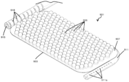
도 5는 하나의 실시 형태 상처 치료 디바이스의 상부 사시도이다.
도 6은 도 5의 디바이스의 밑면 사시도이다.
도 7은 디바이스를 통한 예시적인 유체 유동을 예시하는, 도 5 및 도 6의 디바이스의 밑면 사시도이다.
도 8은 라인 YY를 따르는 절결을 예시하는 도 5의 상부 사시도이다.
도 9는 라인 YY를 통한 도 5의 디바이스의 측면도이다.
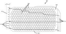
도 10은 디바이스가 특정 치료 부위에 끼워맞춤되도록 트리밍될 수 있는 방법을 보여주는, 도 5의 디바이스의 평면도이다.
도 11은 도 10에 도시된 바와 같이 트리밍된 디바이스의 평면도이다.
도 12는 도 10의 트리밍된 디바이스의 상부 사시도이다.
도 13은 도 10의 트리밍된 디바이스의 밑면 사시도이다.
도 14는 디바이스 및 상처 부위를 통한 유체 유동을 예시하는, 디바이스 입구 채널의 축을 따라 취해진 디바이스의 측단면도이다.
도 15는 디바이스 및 상처 부위를 통한 유체 유동을 예시하는, 디바이스 입구 채널의 축을 따라 취해진 도 10 내지 도 13의 트리밍된 디바이스의 측부 사시도이다.
도 16은 상처 부위에서 도 5 내지 도 15의 디바이스의 배치를 예시하는 절결 측면도이다.
도 17은 디바이스 및 상처 부위 위에 폐색 층을 배치하는 단계를 예시하는, 도 16에 대응하는 절결 측면도이다.
도 18은 디바이스 및 상처 부위 위의 제자리에 있는 폐색 층을 예시하는, 도 16 및 도 17에 대응하는 절결 측면도이다.
도 19는 생체흡수성 재료가 내부에 배치된 상처 부위를 예시하는 절결 측면도이다.
도 20은 생체흡수성 재료와 함께 디바이스 및 상처 부위 위에 폐색 층을 배치하는 단계를 예시하는, 도 19에 대응하는 절결 측면도이다.
도 21은 생체흡수성 재료 위에 위치된 도 5 내지 도 15의 디바이스를 보여주고 디바이스 위에 폐색 층을 배치하는 단계를 예시하는, 도 19 및 도 20에 대응하는 절결 측면도이다.
도 22는 상처 부위에 설치된 제2 실시 형태 NPWT 디바이스를 예시하는 개략적인 단면도이다.
도 23은 상처 부위에 설치된 제3 실시 형태 NPWT 디바이스를 예시하는 개략적인 단면도이다.
도 24는 상처 부위에 설치된 제4 실시 형태 NPWT 디바이스를 예시하는 개략적인 단면도이다.
도 25는 스페이서의 단면 프로파일을 예시하는, 디바이스의 단면 축을 따라 취해진 도 5 내지 도 15의 디바이스의 일부분의 측단면도이다.
도 26은 추가(제5) 실시 형태 상처 치료 디바이스의 상부 사시도이다.
도 27은 도 26의 디바이스의 밑면 사시도이다.
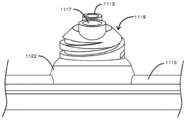
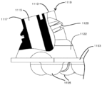
도 28은 도 26 및 도 27의 디바이스의 몸체에 대한 디바이스 입구 포트와 출구 포트 사이의 연결부의 상세도이다.
도 29는 도 28에 대응하는 분해 상세도이다.
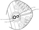
도 30은 디바이스의 밑면을 따르는 치료 유체의 유동을 위한 예시적인 유체 유동 경로를 예시하는, 도 26 내지 도 29의 디바이스의 밑면도이다.
도 31은 도 26 내지 도 30의 디바이스의 평면도이다.
도 32는 디바이스 입구를 통한 유동을 보여주는, 도 31의 라인 AA를 통해 취해진 단면도이다.
도 33은 디바이스 출구를 통한 유동을 보여주는, 도 31의 라인 BB를 통해 취해진 단면도이다.
도 34는 스페이서의 단면 프로파일에 대한 대안적인 형상을 보여주고 압축 하중 하에서의 스페이서의 변화하는 프로파일을 예시하는 개략적인 측단면도이다.
도 35는 입구 채널의 단면 프로파일을 보여주는, 입구 및 출구 커넥터가 제거된 도 26 내지 도 29의 디바이스의 절결 단부도이다.
도 36은 출구 채널의 단면 프로파일을 보여주는, 도 26 내지 도 29의 디바이스의 절결 측면도이다.
도 37은 대안적인 실시 형태 디바이스의 몸체에 대한 디바이스 입구 포트와 출구 포트 사이의 연결부의 상세 평면도이다.
도 38은 도 37에 대응하는 밑면도이다.
도 39는 도 37 및 도 38의 실시 형태의 디바이스의 몸체에 대한 입구 포트와 출구 포트의 연결부의 상부 사시도이다.
도 40은 도 39에 도시된 연결부의 분해 사시도이다.
도 41은 도 37 내지 도 40에 도시된 실시 형태의 커넥터 구성요소의 밑면 사시도이다.
도 42는 도 37 내지 도 41에 도시된 실시 형태의 커넥터 구성요소의 상부 사시도이다.
도 43은 입구를 통한 유동을 보여주는, 디바이스 입구를 통한, 도 37 내지 도 42의 디바이스를 통해 취해진 단면도이다.
도 44는 출구를 통한 유동을 보여주는, 디바이스 출구를 통한, 도 37 내지 도 42의 디바이스를 통해 취해진 단면도이다.
도 45는 추가의 대안적인 실시 형태 디바이스의 몸체에 대한 디바이스 입구 포트와 출구 포트 사이의 연결부의 상세 평면도이다.
도 46은 도 45에 대응하는 밑면도이다.
도 47은 도 45 및 도 46의 실시 형태의 디바이스의 몸체에 대한 입구 포트와 출구 포트의 연결부의 상부 사시도이다.
도 48은 도 47에 도시된 연결부의 분해 사시도이다.
도 49는 도 45 내지 도 48에 도시된 실시 형태의 커넥터 구성요소의 밑면 사시도이다.
도 50은 도 45 내지 도 48에 도시된 실시 형태의 커넥터 구성요소의 상부 사시도이다.
도 51은 입구를 통한 유동을 보여주는, 디바이스 입구를 통한, 도 45 내지 도 48의 디바이스를 통해 취해진 단면도이다.
도 52는 출구를 통한 유동을 보여주는, 디바이스 출구를 통한, 도 45 내지 도 48의 디바이스를 통해 취해진 단면도이다.
도 53은 추가의(제8) 대안적인 실시 형태 디바이스의 몸체에 대한 디바이스 입구 포트와 출구 포트 사이의 연결부의 상부 상세 사시도이다.
도 54는 도 53에 대응하는 평면도이다.
도 55는 도 54의 라인 F55를 따라 취해진 단면도이다.
도 56은 도 53에 대응하는 상부 단부 사시도이다.
도 57은 도 53에 도시된 연결부의 분해 사시도이다.
도 58은 도 53 내지 도 57에 도시된 실시 형태의 커넥터 구성요소의 상부 사시도이다.
도 59는 도 53 내지 도 57에 도시된 실시 형태의 커넥터 구성요소의 밑면 사시도이다.
도 60은 입구를 통한 유동을 보여주는, 디바이스 입구를 통한, 도 53 내지 도 57의 디바이스를 통해 취해진 단면도이다.
도 61은 출구를 통한 유동을 보여주는, 디바이스 출구를 통한, 도 53 내지 도 57의 디바이스를 통해 취해진 단면도이다.
도 62는 제9 실시 형태 디바이스의 상부 사시도이다.
도 63은 도 62의 디바이스의 밑면 사시도이다.
도 64는 디바이스의 밑면을 따르는 치료 유체의 유동을 위한 예시적인 유체 유동 경로를 예시하는, 도 62 및 도 63의 디바이스의 밑면도이다.
도 65는 도 62 내지 도 64의 디바이스의 우측면도이다.
도 66은 도 62 내지 도 64의 디바이스의 좌측면도이다.
도 67은 도 62 내지 도 66의 디바이스 내의 스페이서의 단면 프로파일을 보여주고 압축 하중 하에서의 스페이서의 변화하는 프로파일을 예시하는 개략적인 측단면도이다.
도 68은 분할된 튜브 구성을 갖는 제9 실시 형태 디바이스의 상부 사시도이다.
도 69는 도 68의 디바이스의 밑면 사시도이다.
도 70은 도 68 및 도 69의 디바이스의 밑면도이다.
도 71은 입구 채널을 보여주는, 도 68 내지 도 70의 디바이스의 절결 단부도이다.
도 72는 도 68 내지 도 70의 디바이스의 절결 측면도이다.
도 73은 도 68 내지 도 70의 디바이스 내의 스페이서의 단면 프로파일을 보여주고 압축 하중 하에서의 스페이서의 변화하는 프로파일을 예시하는 개략적인 측단면도이다.
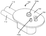
도 74는 커넥터가 생략된, 입구 포트 및 출구 포트에 대안적인 실시 형태 커넥터 부분을 갖는 제10 실시 형태 디바이스의 상부 사시도이다.
도 75는 커넥터가 생략된, 도 74에 도시된 실시 형태의 연결부 보스의 단부도이다.
도 76은 도 75의 연결부 보스의 측부 절결도이다.
도 77은 커넥터와 조립된 도 75 및 도 76의 연결부 보스의 단부 절결도이다.
도 78은 커넥터와 조립된 도 75 내지 도 77의 연결부 보스의 측면도이다.
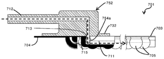
도 79는 도 76에 대응하지만, 커넥터에 입구 도관 및 출구 도관이 결합된 도면이다.
도 80은 도 79에 대응하는 분해도이다.
도 81은 도 74의 디바이스의 커넥터 부분의 상세 평면도이다.
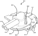
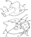
도 82는 입구 포트 및 출구 포트에 대안적인 실시 형태 커넥터 부분을 갖는 추가의(제11) 실시 형태 디바이스의 상부 사시도이다.
도 83은 도 82에 도시된 실시 형태의 입구 및 출구 커넥터 부분의 단부도이다.
도 84는 도 83의 커넥터 부분의 측부 절결도이다.
도 85는 대안적으로 형상화된 스페이서를 갖는 제12 실시 형태 디바이스의 밑면 사시도이다.
도 86은 도 85의 디바이스의 상부 사시도이다.
도 87은 절결 부분을 갖는, 도 85 및 도 86의 디바이스의 측면도이다.
도 88은 스페이서의 일부가 절결된, 도 85 내지 도 87의 디바이스로부터의 스페이서들 중 하나의 스페이서의 상세 측면도이다.
도 89는 추가의 실시 형태 스페이서를 갖는 디바이스의 일부분의 밑면 사시도이다.
도 90은 도 89에 대응하는 상부 사시도이다.
도 91은 스페이서의 일부가 절결된, 도 89 및 도 90의 디바이스로부터의 스페이서들 중 하나의 스페이서의 상세 측면도이다.
도 92는 다른 추가의 대안적인 실시 형태 스페이서를 갖는 디바이스의 일부분의 밑면 사시도이다.
도 93은 도 92에 대응하는 상부 사시도이다.
도 94는 도 92에 대응하는 밑면도이다.
도 95는 도 92 내지 도 94의 디바이스로부터의 스페이서들 중 2개의 스페이서를 통한 측부 단면 상세도이다.
도 96은 다른 추가의 실시 형태 스페이서를 갖는 디바이스의 일부분의 밑면 사시도이다.
도 97은 도 96에 대응하는 상부 사시도이다.
도 98은 도 96에 대응하는 밑면도이다.
도 99는 도 96 내지 도 98의 디바이스로부터의 스페이서들 중 4개의 스페이서를 통한 측부 단면 상세도이다.
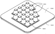
도 100은 언더마이닝(undermining)에 의해 생성된 공동을 충전하기 위해 내부에 생체흡수성 재료의 다수의 작은 충전제 조각이 배치된 언더마이닝을 갖는 상처 부위를 예시하는 절결 측면도이다.
도 101은 작은 충전제 조각 및 상처 부위 위에 생체흡수성 재료의 시트를 배치하는 단계를 예시하는, 도 100에 대응하는 절결 측면도이다.
도 102는 상처 부위에 위치된 도 5 내지 도 15의 디바이스를 보여주고 디바이스 위에 폐색 층을 배치하는 단계를 예시하는, 도 100 및 도 101에 대응하는 절결 측면도이다.
도 103은 디바이스 및 상처 부위 위의 제자리에 있는 폐색 층을 예시하는, 도 100 내지 도 102에 대응하는 절결 측면도이다.
도 104는 본 명세서에 기술된 적어도 하나의 실시 형태에 따른 음압 치료(negative pressure treatment, NPT) 시스템의 하이-레벨 개략 표현을 제공한다.
도 105는 외부 상처에 적용되는 도 104의 시스템을 도시한다.
도 106은 도 104의 시스템의 진공 유닛의 개략 표현이다.
도 107은 도 104의 시스템의 개략 표현이다.
도 108은 도 4에 도시된 음압 치료(NPT) 시스템의 시스템의 개략 표현이다.
도 109는 도 4의 음압 치료(NPT) 시스템의 추가의 대안적인 구성의 개략 표현이다.The present invention will now be described with reference to the accompanying drawings by way of example only.
1 is a schematic diagram of a prior art NPWT system.
Figure 2 is a cutaway side view of a prior art device at a wound site, illustrating provision of fluid flow to the device.
FIG. 3 is a cutaway side view of the prior art device of FIG. 2 illustrating removal of fluid flow from the device.
Figure 4 is a schematic diagram of the NPWT system.
Figure 5 is a top perspective view of one embodiment wound treatment device.
Figure 6 is a bottom perspective view of the device of Figure 5.
Figure 7 is a bottom perspective view of the device of Figures 5 and 6, illustrating example fluid flow through the device.
Figure 8 is a top perspective view of Figure 5 illustrating a cut along line YY.
Figure 9 is a side view of the device of Figure 5 through line YY.
Figure 10 is a top view of the device of Figure 5, showing how the device can be trimmed to fit a specific treatment area.
Figure 11 is a top view of the device trimmed as shown in Figure 10.
Figure 12 is a top perspective view of the trimmed device of Figure 10.
Figure 13 is a bottom perspective view of the trimmed device of Figure 10.
Figure 14 is a cross-sectional side view of the device taken along the axis of the device entrance channel, illustrating fluid flow through the device and wound site.
Figure 15 is a side perspective view of the trimmed device of Figures 10-13 taken along the axis of the device inlet channel, illustrating fluid flow through the device and wound site.
Figure 16 is a cutaway side view illustrating placement of the device of Figures 5-15 at a wound site.
FIG. 17 is a cutaway side view corresponding to FIG. 16 illustrating the step of disposing the occlusive layer over the device and wound site.
Figure 18 is a cutaway side view corresponding to Figures 16 and 17 illustrating the device and the occlusive layer in place over the wound site.
Figure 19 is a cutaway side view illustrating a wound area with bioabsorbable material disposed therein.
FIG. 20 is a cutaway side view corresponding to FIG. 19 illustrating the step of disposing the occlusive layer over the device and wound site with the bioabsorbable material.
Figure 21 is a cutaway side view corresponding to Figures 19 and 20, showing the device of Figures 5-15 positioned over a bioabsorbable material and illustrating the step of disposing an occlusive layer over the device.
Figure 22 is a schematic cross-sectional view illustrating a second embodiment NPWT device installed at a wound site.
Figure 23 is a schematic cross-sectional view illustrating a third embodiment NPWT device installed at a wound site.
Figure 24 is a schematic cross-sectional view illustrating a fourth embodiment NPWT device installed at a wound site.
Figure 25 is a side cross-sectional view of a portion of the device of Figures 5-15 taken along the cross-sectional axis of the device, illustrating the cross-sectional profile of the spacer.
Figure 26 is a top perspective view of a further (fifth) embodiment wound treatment device.
Figure 27 is a bottom perspective view of the device of Figure 26.
Figure 28 is a detailed view of the connection between the device inlet port and outlet port for the body of the device of Figures 26 and 27;
Figure 29 is an exploded detailed view corresponding to Figure 28.
Figure 30 is a bottom view of the device of Figures 26-29, illustrating an example fluid flow path for flow of therapeutic fluid along the underside of the device.
Figure 31 is a top view of the device of Figures 26 to 30.
Figure 32 is a cross-sectional view taken through line AA of Figure 31, showing flow through the device inlet.
Figure 33 is a cross-sectional view taken through line BB in Figure 31, showing flow through the device outlet.
Figure 34 is a schematic side cross-sectional view showing alternative shapes for the cross-sectional profile of the spacer and illustrating the changing profile of the spacer under compressive loading.
Figure 35 is a cutaway end view of the device of Figures 26-29 with the inlet and outlet connectors removed, showing a cross-sectional profile of the inlet channel.
Figure 36 is a cutaway side view of the device of Figures 26-29, showing a cross-sectional profile of the outlet channel.
37 is a detailed plan view of a connection between a device inlet port and an outlet port to the body of an alternative embodiment device.
Figure 38 is a bottom view corresponding to Figure 37.
Figure 39 is a top perspective view of a connection of an inlet port and an outlet port to the body of the device of the embodiment of Figures 37 and 38;
FIG. 40 is an exploded perspective view of the connection portion shown in FIG. 39.
Figure 41 is a bottom perspective view of the connector component of the embodiment shown in Figures 37-40.
Figure 42 is a top perspective view of the connector component of the embodiment shown in Figures 37-41.
Figure 43 is a cross-sectional view taken through the device of Figures 37-42, through the device inlet, showing flow through the inlet.
Figure 44 is a cross-sectional view taken through the device of Figures 37-42, through the device outlet, showing flow through the outlet.
Figure 45 is a detailed plan view of a connection between a device inlet port and an outlet port to the body of a further alternative embodiment device.
Figure 46 is a bottom view corresponding to Figure 45.
Figure 47 is a top perspective view of a connection of an inlet port and an outlet port to the body of the device of the embodiment of Figures 45 and 46;
Figure 48 is an exploded perspective view of the connection shown in Figure 47.
Figure 49 is a bottom perspective view of the connector component of the embodiment shown in Figures 45-48.
Figure 50 is a top perspective view of the connector component of the embodiment shown in Figures 45-48.
Figure 51 is a cross-sectional view taken through the device of Figures 45-48, through the device inlet, showing flow through the inlet.
Figure 52 is a cross-sectional view taken through the device of Figures 45-48, through the device outlet, showing flow through the outlet.
Figure 53 is a top detailed perspective view of the connection between the device inlet port and outlet port to the body of a further (eighth) alternative embodiment device.
Figure 54 is a plan view corresponding to Figure 53.
Figure 55 is a cross-sectional view taken along line F55 in Figure 54.
Figure 56 is a top end perspective view corresponding to Figure 53;
Figure 57 is an exploded perspective view of the connection portion shown in Figure 53.
Figure 58 is a top perspective view of the connector component of the embodiment shown in Figures 53-57.
Figure 59 is a bottom perspective view of the connector component of the embodiment shown in Figures 53-57.
Figure 60 is a cross-sectional view taken through the device of Figures 53-57, through the device inlet, showing flow through the inlet.
Figure 61 is a cross-sectional view taken through the device of Figures 53-57, through the device outlet, showing flow through the outlet.
Figure 62 is a top perspective view of the ninth embodiment device.
Figure 63 is a bottom perspective view of the device of Figure 62.
Figure 64 is a bottom view of the device of Figures 62 and 63, illustrating an example fluid flow path for flow of therapeutic fluid along the underside of the device.
Figure 65 is a right side view of the device of Figures 62 to 64.
Figure 66 is a left side view of the device of Figures 62 to 64.
Figure 67 is a schematic side cross-sectional view showing the cross-sectional profile of a spacer in the device of Figures 62-66 and illustrating the changing profile of the spacer under compressive loading.
Figure 68 is a top perspective view of a ninth embodiment device with a split tube configuration.
Figure 69 is a bottom perspective view of the device of Figure 68.
Figure 70 is a bottom view of the device of Figures 68 and 69.
Figure 71 is a cutaway end view of the device of Figures 68-70, showing the inlet channel.
Figure 72 is a cutaway side view of the device of Figures 68-70.
Figure 73 is a schematic side cross-sectional view showing the cross-sectional profile of a spacer in the device of Figures 68-70 and illustrating the changing profile of the spacer under compressive loading.
Figure 74 is a top perspective view of a tenth embodiment device with alternative embodiment connector portions at the inlet and outlet ports, with the connectors omitted.
Figure 75 is an end view of the connection boss of the embodiment shown in Figure 74, with the connectors omitted.
Figure 76 is a side cutaway view of the connection boss of Figure 75.
Figure 77 is a cutaway end view of the connection boss of Figures 75 and 76 assembled with a connector.
Figure 78 is a side view of the connection boss of Figures 75-77 assembled with a connector.
Figure 79 corresponds to Figure 76, but with the inlet conduit and outlet conduit coupled to the connector.
Figure 80 is an exploded view corresponding to Figure 79.
Fig. 81 is a detailed plan view of the connector portion of the device of Fig. 74;
Figure 82 is a top perspective view of a further (eleventh) embodiment device with alternative embodiment connector portions at the inlet and outlet ports.
Figure 83 is an end view of the inlet and outlet connector portions of the embodiment shown in Figure 82.
Figure 84 is a side cutaway view of the connector portion of Figure 83;
Figure 85 is a bottom perspective view of a twelfth embodiment device with alternatively shaped spacers.
Figure 86 is a top perspective view of the device of Figure 85.
Figure 87 is a side view of the device of Figures 85 and 86, with a cut-out portion.
Figure 88 is a detailed side view of one of the spacers from the device of Figures 85-87 with a portion of the spacer cut away.
Figure 89 is a bottom perspective view of a portion of a device with additional embodiment spacers.
Figure 90 is a top perspective view corresponding to Figure 89.
Figure 91 is a detailed side view of one of the spacers from the device of Figures 89 and 90 with a portion of the spacer cut away.
Figure 92 is a bottom perspective view of a portion of a device with another additional alternative embodiment spacer.
Figure 93 is a top perspective view corresponding to Figure 92.
Figure 94 is a bottom view corresponding to Figure 92.
Figure 95 is a side cross-sectional detail through two of the spacers from the device of Figures 92-94.
Figure 96 is a bottom perspective view of a portion of a device with another additional embodiment spacer.
Figure 97 is a top perspective view corresponding to Figure 96.
Figure 98 is a bottom view corresponding to Figure 96.
Figure 99 is a side cross-sectional detail through four of the spacers from the device of Figures 96-98.
Figure 100 is a cutaway side view illustrating a wound site with undermining with multiple small filler pieces of bioabsorbable material placed therein to fill the cavity created by undermining.
Figure 101 is a cutaway side view corresponding to Figure 100, illustrating the steps of placing a small piece of filler and a sheet of bioabsorbable material over a wound site.
FIG. 102 is a cutaway side view corresponding to FIGS. 100 and 101 showing the device of FIGS. 5-15 positioned at a wound site and illustrating the steps of disposing an occlusive layer over the device.
Figure 103 is a cutaway side view corresponding to Figures 100-102, illustrating the device and the occlusive layer in place over the wound site.
104 provides a high-level schematic representation of a negative pressure treatment (NPT) system according to at least one embodiment described herein.
Figure 105 shows the system of Figure 104 applied to an external wound.
Figure 106 is a schematic representation of the vacuum unit of the system of Figure 104.
Figure 107 is a schematic representation of the system of Figure 104.
Figure 108 is a schematic representation of the system of the negative pressure therapy (NPT) system shown in Figure 4.
Figure 109 is a schematic representation of a further alternative configuration of the negative pressure therapy (NPT) system of Figure 4.
I.I. 정의Justice
본 명세서에서 사용되는 바와 같은 용어 "세포외 기질"(ECM)은 탈세포화된 동물 또는 인간 조직을 지칭하고, 구조적 무결성을 위한 기질 및 다른 재료를 운반하기 위한 프레임워크를 제공한다.As used herein, the term “extracellular matrix” (ECM) refers to decellularized animal or human tissue and provides a framework for transporting matrix and other materials for structural integrity.
본 명세서에서 사용되는 바와 같은 용어 "탈세포화"는 조직 또는 기관의 일부분으로부터, 예를 들어 ECM으로부터, 세포 및 그의 관련 잔해를 제거하는 것을 지칭한다.As used herein, the term “decellularization” refers to the removal of cells and their associated debris from a portion of a tissue or organ, such as from the ECM.
본 명세서에서 사용되는 바와 같은 용어 "중합체 재료"는 많은 반복되는 하위단위(subunit)를 포함하는 대분자 또는 거대분자를 지칭하며, 폴리펩티드 및 단백질(예컨대, 콜라겐), 다당류(예컨대, 알긴산염) 및 다른 생중합체, 예컨대 당단백질을 포함하지만 이로 한정되지 않는 자연 재료일 수 있거나, 또는 폴리프로필렌, 폴리테트라플루오로에틸렌, 폴리글리콜산, 폴리락트산 및 폴리에스테르를 포함하지만 이로 한정되지 않는 합성 재료일 수 있다.As used herein, the term “polymeric material” refers to large molecules or macromolecules containing many repeating subunits, such as polypeptides and proteins (e.g., collagen), polysaccharides (e.g., alginate), and It may be a natural material, including but not limited to other biopolymers, such as glycoproteins, or it may be a synthetic material, including but not limited to polypropylene, polytetrafluoroethylene, polyglycolic acid, polylactic acid, and polyesters. there is.
본 명세서 및 청구범위에서, 용어 '음압' 및 '진공 압력'은 대기압 미만의 게이지 압력 및 대기압 미만의 절대 압력을 의미하기 위해 상호교환가능하게 사용될 수 있다. 대안적인 용어는 '대기압 미만 압력(sub-atmospheric pressure)', '흡입 압력(suction pressure)' 또는 '감소된 압력'을 포함한다. 예를 들어, 100 mmHg의 음압 또는 진공 압력은 -100 mmHg 게이지 압력 또는 약 660 mmHg 절대 압력이다. 용어 '더 높은', '증가'는, 음압 또는 진공 압력과 관련하여 사용될 때, 더 높은 음압 또는 증가하는 음압을 의미하는 것으로 의도된다. 예를 들어, -150 mmHg의 게이지 압력(610 mmHg 절대 압력)은 -100 mmHg의 게이지 압력(660 mmHg 절대 압력)보다 더 높다. 유사하게, 용어 '더 낮은', '감소'는, 음압 또는 진공 압력과 관련하여 사용될 때, 더 낮은 음압 또는 감소하는 음압을 의미하는 것으로 의도된다. 예를 들어, -100 mmHg의 게이지 압력은 -150 mmHg의 게이지 압력보다 더 낮다.In this specification and claims, the terms 'negative pressure' and 'vacuum pressure' may be used interchangeably to mean subatmospheric gauge pressure and subatmospheric absolute pressure. Alternative terms include 'sub-atmospheric pressure', 'suction pressure' or 'reduced pressure'. For example, a negative or vacuum pressure of 100 mmHg is -100 mmHg gauge pressure, or approximately 660 mmHg absolute pressure. The terms 'higher', 'increasing', when used in relation to sound pressure or vacuum pressure, are intended to mean higher or increasing sound pressure. For example, a gauge pressure of -150 mmHg (610 mmHg absolute) is higher than a gauge pressure of -100 mmHg (660 mmHg absolute). Similarly, the terms 'lower', 'reduced', when used in relation to sound pressure or vacuum pressure, are intended to mean lower or decreasing sound pressure. For example, a gauge pressure of -100 mmHg is lower than a gauge pressure of -150 mmHg.
본 명세서 및 청구범위에서, 문맥상 달리 나타내지 않는 한, 용어 '삼출물'은 환자의 상처 부위로부터 제거된 임의의 유체를 의미하는 것으로 의도된다. 예를 들어, 삼출물은 환자에 의해 생성된 유체, 및/또는 시스템에 의해 상처 부위에 적용된 유체를 포함할 수 있으며, 이는 공기 또는 치료 유체, 예컨대, 식염수, 또는 약물을 제공하는 유체, 또는 주사에 의한 것과 같은 별개의 루트를 통해 상처 부위에 치료 유체를 도입하거나 제공했을 수 있는 외과적 개입으로부터의 유체를 포함한다.In the specification and claims, unless the context indicates otherwise, the term 'exudate' is intended to mean any fluid removed from the wound site of a patient. For example, exudates may include fluids produced by the patient, and/or fluids applied to the wound site by the system, such as air or therapeutic fluids such as saline, or fluids that provide medication, or injections. Includes fluids from surgical interventions that may have introduced or provided therapeutic fluids to the wound site through a separate route, such as by
II.II. 디바이스device
이제, 도 4 내지 도 99를 참조하여 다양한 실시 형태가 기술될 것이다. 이러한 도면에서, 달리 기술되지 않는 한, 유사한 특징부를 나타내기 위해 상이한 실시 형태에서 100의 배수를 추가하여 유사한 참조 번호가 사용된다. 방향 용어, 예컨대 '전방', '후방', '상부', '하부', 및 다른 관련 용어는 하기의 설명에서 단지 설명 및 참조의 용이함을 위해 사용되고, 그것은 제한하는 것으로 의도되지 않는다.Various embodiments will now be described with reference to FIGS. 4-99. In these drawings, unless otherwise noted, like reference numerals with the addition of multiples of 100 are used in different embodiments to indicate like features. Directional terms such as 'anterior', 'posterior', 'upper', 'lower', and other related terms are used in the following description only for ease of description and reference and are not intended to be limiting.
본 발명은 대체적으로, 음압 상처 치료법에서 사용하기 위한 상처 인터페이스 디바이스(1)를 제공한다. 디바이스(1)는 상처 표면과 디바이스 몸체(3)의 상처 대향 표면(7) 사이에 치료 공간을 생성하기 위해 복수의 스페이서(5)를 갖는 가요성 몸체(3)를 갖는다. 치료 공간(43)은 상처로부터의 유체의 전달 및 제거, 및 상처에 대한 음압의 적용을 용이하게 한다. 유체는 기체 또는 액체 또는 둘 모두일 수 있다. 상처 인터페이스 디바이스(1)는 상처 주위에 봉입된 환경을 제공하기 위해 상처주변부(49) 주위에 접착하기 위한 액체 불침투성 폐색 층(45)을 포함하는 다층 상처 드레싱(27)(도 18)의 일부를 형성한다.The present invention generally provides a wound interface device (1) for use in negative pressure wound therapy. The
디바이스(1)는 치료 유체와 같은 유체를 상처 부위에 점적주입하기 위한 입구(11)를 포함한다. 입구(11)는 유체를 입구 포트(13)로부터 디바이스(1)의 제1 단부(2a)에 인접한 영역으로 전달하도록 구성된 통로를 포함한다. 도시된 실시 형태에서, 입구(11)는 채널의 상처 대향 표면(7)에서 폐쇄되고 디바이스의 상단 표면(9)으로 개방되는, 디바이스(1)의 몸체에 제공된 채널을 포함한다. 입구 채널(11)은 디바이스의 제1 방향, 바람직하게는 종방향으로 연장되어, 디바이스(1)의 제1 단부(2a)에 있는 또는 그 근처에 있는 입구 개구(11a)에서 종단된다. 대안적으로, 입구(11)는 추가의 예시적인 실시 형태와 관련하여 더 상세히 후술되는 바와 같이, 디바이스 몸체와 일체형이거나 그에 부착되는 튜브형 도관을 포함할 수 있다.The
상처 치료 공간(43)으로부터의 유체의 제거를 위해 출구(15)가 제공된다. 출구(15)는 제1 단부(2a)의 반대편인 디바이스(1)의 제2 단부(2b)의 인접부로부터 유체를 추출하도록 구성된다. 도시된 실시 형태에서, 출구(15)는, 상대적으로 좁은 출구 채널 개구(16)가 디바이스의 밑면으로 개방되고 디바이스의 상단 표면(9)을 따라 폐쇄되는, 디바이스의 몸체에 제공된 채널을 포함한다. 출구 채널 개구(16)를 포함하는 출구(15)는, 디바이스의 제2 방향, 바람직하게는 횡방향(입구 채널(11)에 수직함)으로 연장되고 디바이스의 제1 단부(2a)를 향해 개방된다. 출구 채널 개구(16)를 포함하는 출구 채널은 바람직하게는, 디바이스(1)의 폭의 주요 부분을 가로질러 연장되어, 디바이스의 전체 폭을 가로질러 그로부터 유체를 출구(15) 내로 끌어당긴다. 출구 채널 개구(16)는 바람직하게는, 상처 표면(42)에 실질적으로 아주 근접하여 제공된다. 상처 표면(42)에 아주 근접하여 제공되는 것은 출구(15)가 치료 유체 및 삼출물의 상당한 부분을 치료 공간(43)으로부터 추출할 수 있게 하여, 치료 공간(43) 내에서의 유체의 풀링(pooling)을 감소시킨다.An
출구 채널 개구(16)는 세장형 슬롯-유사 개구이며, 출구 채널(15)의 반경보다 실질적으로 작은 개구 폭(W)(도 7)을 갖는다. 바람직하게는, 출구 채널 개구의 폭(W)은 반경의 약 절반 미만이다The
도시된 실시 형태에서, 출구 채널 개구(16)는 디바이스(1)의 폭의 대부분을 따라 연장되는 실질적으로 선형인 슬롯이다. 대안적인 실시 형태에서, 출구 채널 개구(16)는 다른 형상을 가질 수 있고, 예를 들어, 출구 채널 개구(16)는 파동형(undulating)일 수 있는데, 예를 들어, 그것은 개구(16)가 제1 위치와 제2 위치 사이에서 교번하는 반복적인 사인파로서 형상화될 수 있으며, 여기서 제1 위치는 상처 표면에 실질적으로 근접해 있고 제2 위치는 디바이스의 상처 대향 표면에 실질적으로 근접해 있다. 그러한 실시 형태는 조직 잔해 및 상처 딱지(wound slough)가 출구 채널 개구를 막는 이벤트에서 유체 유동 경로가 유지됨을 보장하면서 유체가 상처 표면으로부터 수집될 수 있게 하는 데 있어서 추가적인 이점을 제공할 수 있다.In the depicted embodiment,
본 명세서에 도시된 실시 형태에서, 출구 채널 개구(16)의 폭(W)은 출구 채널(15)의 길이를 따라 실질적으로 균일하지만, 대안적인 실시 형태에서, 출구 채널 개구(16)의 폭(W)은 디바이스의 폭을 따라 변할 수 있음이 이해될 것이다. 바람직하게는, 출구 채널 개구의 폭(W)은 약 0.2 mm 내지 약 3 mm이다. 더 바람직하게는, 출구 채널 개구의 폭(W)은 약 0.5 mm 내지 약 1 mm이다. 도 5 내지 도 21에 도시된 실시 형태에서, 출구 채널 개구의 폭(W)은 가장 좁은 지점에서 약 0.6 mm 폭이다. 추가로 후술되는 바와 같이, 디바이스는 전형적으로, 디바이스 출구 포트(17)에 그리고 그의 하류에 유체적으로 연결된 음압 펌프 및 저장소를 갖는 시스템에서 사용된다. 출구 채널 개구(16)의 폭(W)은 전형적으로, 디바이스 하류에서 펌프 또는 저장소까지의 유체 경로를 따르는 최소 단면 치수일 것이다. 이것은 출구 채널 개구(16)의 하류에서 발생하는 폐색의 가능성을 최소화한다.In the embodiment shown herein, the width W of the
출구 채널 개구(16)의 좁은 세장형 특성은 출구(15)가 단일 지점에 제공된 출구에 비해 상처 표면(42)에서 풀링될 수 있는 유체와 유체 연통할 더 높은 가능성을 제공한다. 좁은 개구는, 출구 도관(53) 또는 출구 채널(15)의 폐색을 야기할 수 있는 크기의 큰 혈전, 피브린 및 다른 고형화된 유체 또는 조직 잔해의 통과를 방지함으로써 폐색의 가능성을 감소시키는 협착부(constriction)로서 작용한다. 일부 혈액, 피브린 및 다른 입자는 출구 채널 개구의 폭(W)에 따라, 여전히 출구 채널 개구(16)를 통과할 수 있다. 그러나, 바람직한 실시 형태에서, 배관을 잠재적으로 최종적으로 차단할 임의의 큰 혈전, 피브린 및 다른 고형화된 유체 또는 조직 잔해는 출구 채널 개구(16)를 통해 출구(15) 내로 통과할 수 없다. 또한, 그러한 큰 혈전, 피브린 및 다른 고형화된 유체 또는 조직 잔해가 진공 압력 하에서 출구 채널 개구(16)에 대해 끌어당겨진 경우, 출구 채널 개구가 디바이스의 폭을 따라 이어지기 때문에, 출구 채널 개구(16)의 일부분의 차단은The narrow, elongated nature of the
상처 부위로의 음압의 적용에 악영향을 미칠 것 같지 않은데, 이는 이것이 디바이스의 폭에 걸쳐서 그리고 연결된 치료 공간(43) 전체에 걸쳐서 분포되기 때문이다.This is unlikely to have a detrimental effect on the application of negative pressure to the wound site, as it is distributed across the width of the device and throughout the connected
출구(15)는 유체를 디바이스의 출구 포트(17)로 전달하도록 구성되는데, 이는 음압원에 결합하도록 하기 위한 것이다.The
입구 포트(13)는 유체 공급원에 결합하도록 구성되고, 출구 포트(17)는 음압원에 결합하도록 구성된다. 유체 공급원 및/또는 음압원은 외부 도관을 통해 디바이스에 제공될 수 있다. 도시된 실시 형태에서, 입구 및 출구 포트들(13, 17)은 성형된 부재(19)로부터 연장되어 제공된다. 성형된 부재(19)는, 드레싱의 폐색 층(45)을 통해 연장되기 위해 그리고 외부 유체 공급원 및/또는 음압원과의 결합을 용이하게 하도록, 디바이스 몸체(1)의 반대편 측부로부터, 디바이스(3)의 상단 표면(9)으로부터의 것인 상처 대향 측부(7)로 돌출된다. 성형된 부재(19) 상의 테이퍼링된 그리고 융기된 표면이 외부 도관(들)과의 밀어서 끼워맞춤(push-fit) 연결을 용이하게 하도록 제공되지만, 다른 연결부가 구상된다. 디바이스 몸체와 일체형인 돌출하는 입구 및 출구 포트들(13, 17)을 갖는 것은 공급용 및 제거용 도관들에 대한 디바이스의 연결이 상처로부터 떨어져서 이루어질 수 있게 한다. 이것은, 상처에 가깝게 위치된 강성 구성요소가 상처를 가압함으로써 통증 및 불편함을 야기할 수 있고, 일부 경우에는, 강성 구성요소의 압력이 유지되는 곳에 욕창(pressure sore)을 야기할 수 있기 때문에 유리하다.The
도 7을 참조하면, 스페이서(5)는 디바이스(1)의 제1 단부(2a)와 디바이스의 제2 단부(2b) 사이에 다수의 유체 경로(31)를 한정한다. 유체 경로(31)는 디바이스의 상처 대향 표면(7)과 상처 표면(42) 사이에 형성되어, 출구 포트(17)를 빠져나가기 전에, 입구(11)로부터의 치료 유체 및 상처 삼출물과 같은 상처 유체가 출구(15)를 향해 그리고 그 내로 흐를 수 있게 한다. 다수의 경로(31)를 갖는 것은, 하나의 경로가 차단 상태로 되는 경우에도 디바이스(1)가 상처로부터 유체를 계속 끌어당길 수 있음을 보장한다.Referring to Figure 7, the
스페이서(5)는 스페이서가 구성된 일부분만이 상처 표면(42)과 접촉하도록 형상화된다. 도시된 실시 형태에서, 스페이서(5)는 볼록한 상처 접촉 표면을 갖는 구근형 돌출부이지만, 다른 형상화된 스페이서가 구상되고 일부가 후술된다. 스페이서(5)는 디바이스(1)가 휘어지고 따라서 상처 부위에 순응할 수 있게 하도록 형상화되고 분포되어, 건강한 육아 조직이 스페이서(5)와 상처 표면(42) 사이의 접촉 지점에 형성됨을 보장한다. 스페이서(5)는 또한, 바람직하게는, 치료 공간(43)이 다양한 하중 조건 하에서, 예를 들어 디바이스(1)가 일정 범위의 음압을 받을 때, 또는 환자가 디바이스(1)에 물리적 압력을 가하기 위해 체중을 이동하거나 분산시킬 때의 환경에서, 상처 표면과 디바이스(1) 사이에 실질적으로 유지됨을 보장한다. 스페이서(5)는, 예를 들어 스페이서 벽의 좌굴을 통해, 스페이서(5)의 실질적 붕괴를 방지하도록 형상화되고 분포되어, 이에 의해, 음압의 적용 하에서 치료 공간(43)을 유지한다. 따라서, 스페이서(5)는 스페이서(5)의 실질적 붕괴를 방지하기 위해, 그리고 이에 의해, 음압의 적용 하에서 치료 공간(43)을 유지하기 위해, 충분히 커야 하고, 충분한 벽 두께 및 곡률을 가져야 하며, 충분한 개수여야 한다. 그러나, 스페이서(5)는 디바이스(1)가 상처 표면(42)의 윤곽에 순응하도록 휘어지는 것을 방지할 정도로 또는 제1 단부(2a)로부터 제2 단부(2b)로의 치료 공간(43) 내에서의 유체의 통과를 방지할 정도로 크거나 또는 조밀하게 분포되어서는 안 된다.The
디바이스(1)에 의해 제공되는 음압 상처 치료법을 위한 압력은 바람직하게는 약 30 mmHg 내지 약 200 mmHg, 그리고 더 바람직하게는 약 125 mmHg이다. 제1 단부(2a)로부터 제2 단부(2b)로의 압력 강하는 최소이거나 무시해도 될 정도이고, 이것은 본 명세서에 기술된 디바이스가 종래 기술에 비해 더 낮은 작동 음압에서의 치료법을 제공하는 것을 가능하게 한다.The pressure for negative pressure wound therapy provided by
더 상세히 후술될 일부 실시 형태에서, 디바이스(1)는 생체흡수성 층과 조합하여 상처 치료 시스템에서 사용될 수 있고, 생체흡수성 층은 디바이스와 상처 표면 사이에 배치된다. 스페이서(5)는 생체흡수성 층이 음압 하에서 상처 표면으로부터 들어올려지는 것을 방지하도록 크기설정되고 배열된다. 스페이서(5)는 바람직하게는, 생체흡수성 층이 음압 하에서 상처 표면으로부터 들어올려지는 것을 방지하도록 디바이스의 상처 대향 표면(7)에 걸쳐서 충분한 밀도로 분포된다.In some embodiments, which will be described in more detail below,
도 5 내지 도 9를 참조하면, 스페이서(5)는 디바이스(1)의 몸체(3)의 상처 대향 표면(7)으로부터 연장되어, 스페이서의 정점에서 종단된다. 스페이서는, 바람직하게는 약 1 mm 내지 약 10 mm, 더 바람직하게는 2 mm 내지 5 mm이고, 바람직한 실시 형태에서는, 약 3 mm인 스페이서 높이(4)(도 9)를 갖는다.5-9, the
상처 부위에 걸친 치료 유체 및/또는 음압의 분포를 돕기 위해 스페이서(5)가 형상화되고 이격될 수 있고/있거나, 2차 특징부가 존재할 수 있다. 도 5 내지 도 21에 도시된 디바이스(1)에서, 브리지(21)가 인접한 스페이서들(5) 사이에 제공되고, 치료 유체를 분포시키도록 구성된다. 이러한 실시 형태에서, 브리지(21)는 셰브론형 패턴을 형성하여, 상처 표면을 측방향으로 가로지르고 디바이스의 제2 단부(2b)를 향하는, 예를 들어 디바이스 및/또는 상처 표면의 폭을 가로지르는, 입구 개구(11a)로부터의 치료 유체의 방향을 보조한다.
2차 특징부는 대안적으로, 리브(rib) 또는 상이하게 형상화된 스페이서, 예를 들어 비대칭 스페이서(5)를 포함할 수 있다.The secondary features may alternatively comprise ribs or differently shaped spacers, for example
브리지(21)와 같은 2차 특징부는 바람직하게는, 상처 표면과 접촉하지 않아서, 브리지 표면과 상처 표면 사이의 유체의 유동을 허용한다. 즉, 브리지(21)는 유체 및 음압의 통과를 허용하기 위해 상처 표면과 디바이스 사이에 갭(6)을 제공한다.Secondary features, such as
도 25 및 도 34는 실시 형태에 따른 스페이서(5)를 보여주는, 디바이스의 단면 축을 따라 취해진, 디바이스의 일부분의 측단면도를 도시한다. 도 25에 도시된 실시 형태에서의 스페이서(5)의 프로파일은 더 둥글고 사인파형인 반면, 도 34에 도시된 실시 형태에서의 스페이서(5)의 프로파일은 구근형 또는 언더컷 형상에 더 가깝다. 스페이서 높이(4)가 도시되어 있다.Figures 25 and 34 show cross-sectional side views of a part of the device, taken along the cross-sectional axis of the device, showing a
스페이서(5)의 높이(4) 및 브리지(21)와 상처 표면 사이의 갭(6)은 치료 공간(43)을 한정한다. 휴대용 및 배터리 동력공급식 음압 치료 시스템의 경우, 필요한 지속기간 동안 상처 치유를 촉진하기 위해 상처로의 유체의 공급 및 그로부터의 유체의 제거를 허용하기에 충분한 수단을 제공하면서 음압 치료가 상처를 가로질러 제공됨을 보장하는 것이 가능한 최소 치료 공간(43)을 갖는 것이 가장 바람직하다. 스페이서(5)의 높이(4) 및 브리지(21)와 상처 사이의 갭(6)이 너무 작은 경우, 상처로부터의 잔해 및 유체는 디바이스를 차단하고 상처에 대한 치료 유체 및 음압의 투여를 방지할 수 있다.The height 4 of the
상처 표면과 디바이스(1)의 몸체(3)의 상처 대향 표면 사이의 갭(6)은 스페이서 높이(4)에 의해 결정되고, 바람직하게는 약 0.01 mm 내지 약 10 mm, 더 바람직하게는 약 0.1 mm 내지 약 3 mm이고, 바람직한 실시 형태에서는, 약 1 mm이다. 상처 표면과 브리지(21)의 표면 사이의 갭은 스페이서 높이 미만이다. 치료 공간(43)의 총 자유 부피가 확대될 때, 더 적은 총 자유 부피를 갖는 디바이스와 동일한 레벨의 치료를 제공하기 위해 더 많은 양의 치료 유체가 필요할 수 있다. 확대된 치료 공간(43)은 또한, 전체 시스템을 원하는 레벨의 진공 압력으로 가압하기 위해 진공 펌프 조립체에 제공될 더 많은 에너지를 필요로 할 것이다. 이러한 추가된 에너지 수요는 배터리 동력공급식 음압 치료 펌프가 동작할 수 있는 기간을 단축시킬 수 있다.The
도 5 내지 도 21에 도시된 디바이스(1)에서, 스페이서(5)는 횡단면이 실질적으로 둥글다. 실질적으로 둥근 스페이서(5)를 갖는 것으로 도시된 것과 같은 실시 형태에서, 스페이서(5)는, 바람직하게는 약 2 mm 내지 약 10 mm, 더 바람직하게는 약 3 mm 내지 7 mm이고, 바람직한 실시 형태에서는, 약 5 mm인 직경을 갖는다. 도시된 실시 형태에서, 스페이서(5)는 균일하게 크기설정되지만, 대안적인 실시 형태에서, 스페이서(5)는 상처 표면과 관련하여 그의 위치에 따라 상이한 크기를 가질 수 있고, 예를 들어, 더 큰 직경 및/또는 스페이서 높이를 갖는 스페이서 또는 스페이서들은 상처 표면의 제1 부분에 위치될 수 있고, 더 작은 직경 및/또는 스페이서 높이를 갖는 스페이서 또는 스페이서들은 상처 표면의 제2 부분에 위치될 수 있다.In the
스페이서(5) 및/또는 2차 특징부는 상처에 대한 치료법의 제공 또는 상처의 치유를 추가로 보조할 수 있다. 예를 들어, 스페이서(5) 및/또는 2차 특징부, 및 디바이스의 몸체의 벽 두께는 충분히 가요성일 수 있고, 음압 하에 있을 때 스페이서의 행이 인접한 다른 것을 향해 적어도 부분적으로 수축하도록 형상화되어, 디바이스의 면적이 감소되도록 할 수 있다. 이러한 수축은 상처 표면을 디바이스의 폭 및/또는 종방향에서 적어도 부분적으로 수축된 상태로 당길 수 있다. 버블 유동 또는 슬러그 유동을 생성하는 미리결정된 방식으로, 음압이 제거되거나 감소될 때, 예를 들어 공기 입구 밸브가 미리결정된 기간 동안 주기적으로 개폐될 때, 스페이서(5) 및/또는 2차 특징부의 수축된 상태, 및 이에 따른 상처 표면의 수축된 상태가 해제된다. 상처 부위의 수축 및 수축의 후속 해제는 상처 표면으로의 혈류의 증가에 바람직하며, 이는 치유 과정을 돕는다. 그러나, 디바이스 및 상처 부위가 수축 하에 있는 동안에도 상처 부위를 가로지르는 유체 채널이 개방된 상태로 유지되는 것이 또한 바람직하다. 종래 기술의 디바이스에서, 적용된 음압은 종종, 디바이스가 깊이 면에서 수축되게 하여, 디바이스를 통한 유체 경로를 막는다.The
이러한 효과를 예시하기 위해, 폴리우레탄 백에 NPWT를 위한 공지된 발포체의 샘플을 배치하고, 음압을 적용하고, 디바이스의 거동 및 수축을 관찰하는 실험을 수행하였다. 셰브론 행이 6 mm 이격되고 60도 비스듬하게 놓이고 셰브론의 정점이 디바이스의 중심 종축을 따라 위치된 반복되는 셰브론 패턴으로 배열된 스페이서들의 행을 포함하는, 도 70에 도시된 것과 유사한 디바이스를 사용하여 동일한 실험을 수행하였다. 스페이서는 직경이 5 mm였고, 도 73에 도시된 형상과 유사하게 언더컷 구근형 형상으로 형상화시켰다. 스페이서들을 셰브론 행을 따라 6 mm 이격시켰고, 행 내의 인접한 스페이서들을 브리지를 통해 연결하였다.To illustrate this effect, an experiment was performed in which samples of known foams for NPWT were placed in polyurethane bags, negative pressure was applied, and the behavior and shrinkage of the device was observed. Using a device similar to that shown in Figure 70, comprising rows of spacers arranged in a repeating chevron pattern with the rows of chevrons spaced 6 mm apart and angled at 60 degrees and the apex of the chevrons positioned along the central longitudinal axis of the device. The same experiment was performed. The spacer had a diameter of 5 mm and was shaped into an undercut bulbous shape similar to the shape shown in Figure 73. Spacers were spaced 6 mm apart along the chevron row, and adjacent spacers within a row were connected via bridges.
디바이스는 약 110 mm의 전체 종방향 폭, 약 76 mm의 횡방향 높이 및 약 9 mm의 전체 깊이를 가졌다. 스페이서 및 브리지는 약 1 mm의 실질적으로 일정한 벽 두께를 가졌으며, 이때 디바이스의 상단 표면 내의 공동은 도 5 내지 도 21에 도시된 바와 같이 스페이서에 의해 형성된다. 전체 테스트 디바이스는 중량이 14.47 그램이었다.The device had an overall longitudinal width of approximately 110 mm, a transverse height of approximately 76 mm, and an overall depth of approximately 9 mm. The spacer and bridge had a substantially constant wall thickness of about 1 mm, with the cavity in the top surface of the device being formed by the spacer as shown in FIGS. 5-21. The entire test device weighed 14.47 grams.
전술된 디바이스, Granufoam™ 망상형 폴리우레탄 발포체 드레싱, 및 Whitefoam™ 폴리비닐 알코올 발포체에 대해 테스트를 수행하였다. Granufoam™ 드레싱을 건조 상태에서 테스트하는 한편, 사용을 위한 제조자 지침에 따라 Whitefoam™ 폴리비닐 알코올 발포체를 테스트 전에 수화시켰다.Tests were performed on the devices described above, Granufoam™ reticulated polyurethane foam dressing, and Whitefoam™ polyvinyl alcohol foam. Granufoam™ dressings were tested dry, while Whitefoam™ polyvinyl alcohol foam was hydrated prior to testing according to the manufacturer's instructions for use.
각자의 테스트 디바이스/드레싱을 밀봉된 폴리우레탄 백에 배치함으로써 각각의 테스트를 수행하였다. 백을 통과하는 도관을 디바이스 위에서 중심에 위치시키고, 조정가능한 음압원에 연결하였다. 각각의 테스트 시편의 길이(종방향), 폭(횡방향 치수) 및 깊이를 0 mmHg(주변), 50 mmHg 및 150 mmHg의 시스템 압력 레벨에서 측정하였다. 이러한 테스트로부터의 결과는 하기 표에 나타나 있다.Each test was performed by placing the respective test device/dressing in a sealed polyurethane bag. A conduit passing through the bag was centered over the device and connected to an adjustable negative pressure source. The length (longitudinal), width (transverse dimension) and depth of each test specimen were measured at system pressure levels of 0 mmHg (peripheral), 50 mmHg and 150 mmHg. The results from these tests are shown in the table below.
디바이스 몸체(3)는 액체 및 공기 불침투성이다. 즉, 디바이스(1)는 출구(15)를 통하는 것 외에는, 디바이스의 상처 접촉 측으로부터 디바이스(1)의 상단으로의 액체 또는 기체의 투과를 허용하는 개구부 또는 기공을 포함하지 않는다. 이것은 음압 치료 공간(43)의 5개의 형성을 용이하게 하고, 입구 포트(13)를 통해 입구 채널(11)을 따라 흐르는 유체가 디바이스의 단부에서 입구 개구(11a)에 도달할 때까지 디바이스(9)의 상단 표면 상에 유지됨을 보장한다.The
스페이서(5)를 포함하는 디바이스 몸체(3)는 탄성중합체와 같은 가요성, 바람직하게는 탄성 재료를 포함한다. 이것은 디바이스가 다양한 10개의 상처 표면의 윤곽에 순응하도록 휘는 것을 가능하게 한다. 바람직하게는, 디바이스는 실리콘을 포함하고, 상처가 디바이스(1)에 부착되지 않음을 추가로 보장하기 위해 저접착력 실리콘 코팅을 포함할 수 있다. 대안적으로, 디바이스(1)는 당업자에게 명백할 바와 같이 임의의 다른 적합한 탄성중합체 재료를 포함할 수 있는데, 예를 들어, 그것은 폴리우레탄, 열가소성 폴리우레탄, 열가소성 탄성중합체, 열가소성 가황물 및/또는 고무 블렌드 중 하나 이상을 포함할 수 있다.The
디바이스 몸체(3)는 필요한 가요성, 압축 하중에 대한 저항, 및 내구성을 제공하도록 선택되는 벽 두께를 갖는다. 도시된 실시 형태에서의 디바이스 몸체의 벽 두께는 바람직하게는 약 0.01 mm 내지 약 10 mm, 더 바람직하게는 약 0.1 mm 내지 5 mm이고, 바람직한 실시 형태에서는, 약 1 mm이다. 도시된 실시 형태에서, 디바이스 몸체(3)는 전체에 걸쳐 균일한 벽 두께를 갖는다. 대안적인 실시 형태에서, 벽 두께는 디바이스 몸체의 상이한 부분들에 걸쳐 변할 수 있다. 스페이서(5)의 벽 두께는 디바이스 몸체의 두께와 동일하거나 상이할 수 있고/있거나 브리지(21)의 벽 두께와 동일하거나 상이할 수 있다.The
도시된 실시 형태에서, 스페이서들(5)은 그들이 반복 패턴으로 서로 이격되도록 위치된다. 스페이서들(5) 사이의 간격은 바람직하게는 약 2 mm 내지 약 20 mm, 더 바람직하게는 약 5 mm 내지 10 mm이고, 바람직한 실시 형태에서는, 약 7 mm이다. 도시된 실시 형태에서, 스페이서(5)가 행에 위치되고, 각각의 행은 입구(11)의 종축에 대해 대략 60도에 위치되는 제1 축을 따라 이어지고 입구(11)로부터 디바이스 몸체(3)의 에지를 향해 외향 연장되지만, 다른 배열이 예상된다.In the depicted embodiment, the
도 10 내지 도 13을 참조하면, 디바이스(1)는 다양한 상처 부위의 주연부 내에 끼워맞춤되도록 트리밍가능하다. 도 10에 도시된 바와 같이, 디바이스(1)는 주어진 상처와 일치하는 크기로 트리밍될 수 있다. 크기에 맞게 트리밍할 때, 트림 라인(23)이 입구 채널(11)을 가로질러 연장되어 디바이스를 단축시키고/시키거나, 필요한 경우, 출구 채널(15)을 가로질러 연장되어 디바이스를 좁힐 수 있다. 트리밍된 디바이스(25)(도 11)는 도시된 바와 같이, 입구 및 출구 포트들(13, 17)을 포괄하는 것이 중요하다.10-13,
도 11 내지 도 13은 트리밍된 디바이스(25)를 도시한다. 이러한 디바이스에서, 입구 채널(11)은 디바이스의 제1 단부(2a)에서 종단되며, 따라서, 상처로 전달되는 임의의 치료 유체가 디바이스의 제1 단부(2a)와 상처의 에지 사이의 치료 공간에 들어갈 것이다. 디바이스의 제1 단부(2a)는 디바이스가 트림 라인(23)에서 종단되는 곳에 의해 한정될 수 있다. 출구(15)는 제1 단부(2a)의 반대편인, 디바이스의 제2 단부(2b)에 인접하게 유체를 추출하도록 구성된다. 도시된 예에서, 하나의 지점에서, 절단선은 출구 채널(15)을 통해 연장되어, 출구 채널(15)이 디바이스의 측부 에지(15a)로 개방되고 그곳에서 종단되게 한다. 사용 중에, 디바이스가 상처 표면과 아주 근접하여 끼워맞춤되도록 끼워맞춤되었다면, 진공 압력은 이러한 개구(15a)에 대해 상처의 면을 당겨서 출구 채널 단부를 밀봉할 것이다.11-13 show the trimmed
도 26 내지 도 36은 제1 실시 형태 디바이스(1)와 비교하여, 입구 및 출구 포트들(513, 517)의 대안적인 배열체 및 대안적인 스페이서 설계(505)를 갖는 대안적인 실시 형태 디바이스(501)를 도시한다. 도 26을 참조하면, 이러한 실시 형태(501)에서, 입구 및 출구 포트들(513, 517)은 몸체의 평면과 실질적으로 평행한 방향에서, 디바이스(501)의 몸체(503)로부터 멀리 연장되는 짧은 도관에 의해 제공된다.26-36 show an
디바이스 몸체(503)로부터 떨어져 연장되는 입구 및 출구 도관들(513, 517)의 배향은 (상처 바로 위에 있는 연결 지점과는 대조적으로) 상처로부터 떨어진 연결 지점에서 유체 공급용 및 제거용 도관들과의 연결을 용이하게 한다. 입구 및 출구 포트들(513, 517)이 각자의 공급용 또는 제거용 도관(도시되지 않음)에 결합되는 연결 지점은 증가된 강성의 영역이다. 결합이 상처에 대해 가압되는 것으로부터의 외상의 가능성을 최소화하거나 회피하기 위해 이러한 더 강성인 결합을 상처로부터 떨어지게 위치시키는 것이 유리하다.The orientation of the inlet and
입구 및 출구 도관들(513, 517)은 디바이스(501)와 일체로 성형되고, 디바이스 몸체(503)의 상단 표면 상의 성형된 보스(519)로부터 연장된다. 디바이스(501)는 바람직하게는, 실리콘 고무와 같은 탄성중합체 재료로부터 성형된다. 보스(519) 내의 내부 통로는 입구 및 출구 도관들(513, 517)과 정렬되고, 도 32 및 도 33의 단면도에 도시된 바와 같이, 각자의 입구 또는 출구 포트들(513, 517)과 유체 연통하는 입구 통로(511) 및 출구 통로(515)의 각자의 부분들을 형성한다.Inlet and
사용 중에, 액체 불침투성 멤브레인(도시되지 않음)이 디바이스(501) 위에 배치되고, 디바이스(501)의 상단 표면(509)에 접착된다. 커버 클립(552)이 커버 클립(552)과 디바이스 몸체(503)와 보스(519) 사이에 멤브레인을 트랩핑(trapping)함으로써 불침투성 멤브레인을 보스(519)에 고정하도록 제공된다. 커버 클립은 또한, 밀봉이 유지됨을 보장하기 위해 디바이스 몸체(503)에 대해 불침투성 물질을 가압하기 위한 편평한 밑면을 갖는 베이스 플레이트(532)를 갖는다. 액체 불침투성 멤브레인은 보스(519)의 형상에 대응하는 형상을 갖는 개구부를 포함하여, 보스가 개구부를 통해 연장되고 커버 클립(552)이 보스(519) 및 개구부 주위에서 디바이스 몸체의 표면에 대해 멤브레인을 가압하여 밀봉부를 생성하도록 할 수 있다. 일부 실시 형태에서, 베이스 플레이트(503a)의 밑면은 불침투성 멤브레인의 상단 표면에 접착되는 접착제를 포함할 수 있다.During use, a liquid impermeable membrane (not shown) is placed over
커버 클립(552)은 성형된 보스(519) 위에 끼워맞춤되도록 형상화되어, 도 32 및 도 33에 도시된 바와 같이 보스(519)와 밀착 끼워맞춤된다. 커버 클립(552)은 립(lip)(553), 및 선택적으로, 디바이스 몸체(503) 상의 하나 이상의 특징부와 확실하게 맞물려서, 커버 클립(552)을 디바이스 몸체에 해제가능하게 고정하기 위한 하나 이상의 다른 특징부를 포함한다. 도시된 실시 형태에서, 립(553)은 디바이스(501)의 언더컷 에지와 맞물리고, 탄성 탭(554)은 디바이스(501)의 상단으로 개방되는 스페이서(505)의 중공부와 맞물린다.The
대안적인 실시 형태에서, 성형된 보스(519)는 보스의 원주의 전부 또는 일부 주위에, 바람직하게는 보스의 베이스에 언더컷을 포함할 수 있다. 이러한 언더컷 리세스는 커버 클립(552) 상의 대응하는 돌출부 또는 클립과 맞물려서 2개의 구성요소들을 함께 로킹할 수 있다.In alternative embodiments, the molded
이러한 실시 형태에서, 출구 채널은 디바이스(501)의 제2 단부(502b)에 인접한, 디바이스(501)의 폭을 실질적으로 가로질러 이어지는 횡방향 채널(515)을 포함한다. 도 27을 참조하면, 출구 채널(515)은 1차, 세장형 슬릿-유사 개구(516)를 갖는다. 1차 개구(516)는 디바이스의 제1 단부(502a)를 향해 개방된다. 또한, 복수의 이격된 2차 슬롯-유사 개구(518)가 1차 개구(515)를 따라 제공된다. 2차 개구(518)는 세장형 1차 개구(516)와 직교하고 그에 인접해 있다. 1차 개구(516)를 폐쇄된 상태로 가압하는 압축력의 이벤트에서, 이러한 2차 개구(518)는 출구 채널(515) 내로의 유체 유동을 허용하기 위해 개방된 상태로 유지된다. 채널(515)은 그의 2개의 단부에서 개방되는데, 이들은 디바이스(501)의 측부 에지로부터 내향으로 이격되어 위치된다.In this embodiment, the outlet channel includes a
출구 채널(515)은 단면이 아치형이어서, 1차 개구(515)로부터의 유체 유동을 출구 도관(517)을 향해, 실질적으로 90도를 통해 지향시킨다.The
이러한 실시 형태(501)에서의 스페이서(505)의 형상 및 배열은 또한, 예시된 제1 디바이스(1)의 형상 및 배열과는 상이하다. 브리지(521)는 일부 스페이서들(505) 사이에, 헤링본-유사 패턴을 따라 제공된다. 그러나, 브리지(521)는 교번하는 스페이서 행들에만 제공된다. 또한, 그러한 브리지(521)를 포함하는 스페이서 행들의 경우, 종방향 입구(511)의 밑면에 연결하기 위한 브리지(521)가 이러한 행들 중 교번하는 행들에만 제공된다. 브리지를 갖는 다른 행들의 경우, 종방향 입구(511)의 밑면과 상기 행 내의 가장 가까운 스페이서 사이에 갭이 존재한다. 이러한 배열은 디바이스의 제1 단부(502a)로부터 디바이스의 제2 단부(502b)로의 유체 유동을 향상시킬 수 있다. 도 30은 디바이스의 제1 단부(502a)에서의 입구(511a)의 단부로부터 출구 채널(515)을 향한 많은 가능한 유동 경로들 중 하나를 도시한다. 이러한 유동 경로는 종방향 입구(511)의 밑면과 가장 가까운 스페이서 사이의 상기 "갭" 사이의 통로를 포함한다. 이러한 스페이서 및 브리지 배열은 또한, 음압 하에 있을 때 디바이스의 더 큰 종방향 및 횡방향 수축 정도를 제공할 수 있다.The shape and arrangement of the
특히 도 34를 참조하면, 스페이서(505)의 벽 두께는 각각의 스페이서의 상이한 부분들에서 다르다. 각각의 스페이서(505)는 디바이스 몸체(503)의 상처 대향 표면(507)에 인접한 '언더컷' 영역(505a)을 갖도록 형상화된다. 각각의 스페이서(505)의 외부 표면은 볼록한 만곡부를 갖고, 디바이스 몸체(503)에 인접한 스페이서(505)의 벽 두께는 좁아서 이러한 '언더컷'(505a)을 생성한다.Referring particularly to Figure 34, the wall thickness of
음압 하에서, 스페이서(505)는 압축되어, 도 34에서 파선(505b)에 의해 예시된 바와 같이, 인접한 스페이서의 벽들이 서로를 향해 불룩해지게 한다. '언더컷' 영역(505a)은 힌지 지점을 제공함으로써 스페이서(505)의 편향을 제어하는 데 도움을 주는데, 이는 스페이서 벽이 이러한 영역(505a)에서 발생하는 그의 가장 얇은 지점을 중심으로 휘어질 가능성이 가장 크기 때문이다. 이에 의해, 언더컷 영역(505a)은, 스페이서가 유체 유동을 완전히 차단하는 방식으로 손상되지 않고, 디바이스(501)가 압축될 때 유체 유동에 대한 채널(505c)이 상처 표면 위에서 유지됨을 보장한다.Under negative pressure,
도 37 내지 도 44는 추가의 대안적인 커넥터(652) 및 입구 및 출구 포트들(613, 617)의 배열체를 갖는 대안적인 실시 형태 디바이스(601)를 도시한다. 도 39 및 도 40을 참조하면, 입구 및 출구 포트들(613, 617)은 디바이스 몸체(603)와 일체형이고, 몸체(603)로부터 위로 연장된다. 입구 및 출구 포트들(613, 617)은 커넥터(652) 내의 상보적 맞물 돌출부 특징부(654)에 결합하도록 형상화된다.37-44 show an
이러한 실시 형태(601)에서, 입구 및 출구 포트(613, 617)는 버섯-유사 형상을 가지며, 이때 언더컷(613a, 617b)은 커넥터와 맞물리기 위한 것이다. 커넥터(652)는 입구 및 출구 포트(613, 617)를 수용하기 위한 상보적 개구부(654a, 654b)를 갖는 베이스 플레이트(632)를 포함한다. 개구부(654a, 654b)의 원주는 각각 각자의 통로 내에서 립으로서 작용하여, 디바이스의 몸체 상의 커넥터의 언더컷과 맞물린다.In this
커넥터(652)는 입구 포트(613)와 결합하기 위한 입구 도관(612) 및 루멘(도 43 참조); 및 출구 포트(617)와 결합하기 위한 출구 도관(616) 및 루멘(도 44)을 포함한다. 커넥터(652)는 임의의 적합한 재료를 포함할 수 있고, 예를 들어, 그것은 열가소성 또는 탄성중합체 재료로부터 성형될 수 있다.
디바이스 몸체는 디바이스(601)의 제2 단부(602b)에 연장 탭(604)을 포함한다. 연장 탭(604)은 커넥터(652)의 베이스 플레이트(632)를 수용하도록 형상화된다. 베이스 플레이트(632)는 디바이스(601)의 상부 표면에 대해 놓이며, 이때 베이스 플레이트의 일부는 연장 탭 상에 안착한다. 사용 중에, 액체 불침투성 폐색 층(도시되지 않음)이 커넥터(652)와 디바이스(601)의 상부 표면 사이에 위치되고, 커넥터의 베이스 플레이트(632)와 인터페이싱하기 위해 연장 탭(604)에 의해 제공되는 추가적인 영역은 폐색 층을 디바이스에 밀봉하기 위해 커넥터(652)와 디바이스(601) 사이에 개선된 클램핑을 제공한다. 액체 불침투성 멤브레인은 입구 및 출구 포트들(613, 617)이 개구부를 통해 연장되고 커넥터(652)와 맞물릴 수 있게 하도록 형상화된 하나 또는 2개의 개구부를 포함할 수 있다.The device body includes an
도 45 내지 도 52는 추가의 대안적인 커넥터(752)를 갖는 제7 실시 형태 디바이스(701)를 도시한다. 도 47 및 도 48을 참조하면, 이러한 실시 형태에서의 입구 및 출구 포트(713, 717)는 디바이스 몸체(703)에 개구부를 포함한다. 입구 포트(713)는 입구 채널(711)의 일 단부에 확대된 개구를 포함한다. 출구 포트(717)는 출구 채널(715)과 유체 연통하는 개구부를 포함한다. 도시된 실시 형태에서, 출구 포트(717)는 슬롯-유사 개구부를 포함한다.45-52 show a
커넥터는 입구 및 출구 포트(713, 717)와 맞물리기 위한 입구 및 출구 맞물림 특징부(754a, 754b)를 포함한다. 입구 및 출구 맞물림 특징부(754a, 754b)는 각자의 입구 또는 출구 포트 개구부에 의한 수용을 위해 커넥터(752)의 베이스 플레이트(732)로부터 연장되는 버섯-유사 돌출부를 포함한다. 돌출부는 각자의 입구 또는 출구 포트 개구부와 맞물리기 위한 표면을 제공하기 위해 언더컷을 갖는다.The connector includes inlet and outlet engagement features 754a, 754b for engaging inlet and
커넥터(752)는 입구 포트(713)와 유체 연통하기 위한 입구 도관(712) 및 루멘(도 51 참조); 및 출구 포트(717)와 유체 연통하기 위한 출구 도관(716) 및 루멘(도 52)을 포함한다.
디바이스(701)는 디바이스의 상단 표면으로부터 돌출되는 위치결정 탭(754)을 포함한다. 위치결정 탭(754)은 커넥터 상의 상보적 위치결정 개구부(755)에 의해 수용되도록 구성된다. 탭(754)은 커넥터(752)의 돌출된 입구 및 출구 맞물림 특징부들(754a, 754b)이 디바이스의 대응하는 입구 및 출구 포트들과 맞물림을 보장하기 위해, 디바이스 몸체(701)와 조립될 때 커넥터가 정확하게 배향됨을 보장하는 것을 돕는다.
위치결정 탭(754)은 또한, 사용자가 커넥터를 향해 그리고 그와 맞물려서 디바이스(701)를 당기는 것을 도움으로써 조립을 도울 수 있다.Positioning
사용 중에, 기밀 밀봉부를 형성하기 위해, 연장 탭(704)에 의해 제공되는 추가적인 영역을 포함하는, 커넥터(752)의 베이스 플레이트(732)와 디바이스(701)의 상부 표면 사이에 액체 불침투성 폐색 층(도시되지 않음)이 클램핑된다. 액체 불침투성 멤브레인은 입구 및 출구 포트들(713, 717) 및 탭(754)이 폐색 층을 통해 연장될 수 있게 하도록 형상화된 하나 이상의 개구부를 포함할 수 있다.During use, a liquid impermeable occlusive layer between the top surface of
도 53 내지 도 61은 추가 실시 형태 디바이스(801)를 도시한다. 이러한 디바이스(801)는 전술된 디바이스(601)와 유사하지만, 보유 탭(854)을 추가로 포함한다. 보유 탭(854)은 커넥터 상의 상보적 개구부(855)에 의한 수용을 위해 디바이스(801)의 상단 표면으로부터 돌출된다. 보유 탭은 탭의 베이스 근처에 협소해진 또는 노치된 부분을 포함한다. 이러한 협소해진 부분의 높이는 수용 개구부(855)에서의 커넥터 베이스 플레이트(853)의 두께에 실질적으로 대응한다. 좁은 영역(854a) 위에서, 탭(854)은 좁은 영역(854a) 바로 위의 견부에서의 가장 넓은 지점으로부터, 좁은 영역보다 더 작은 폭을 가질 수 있는, 탭의 상단으로 테이퍼링된다.53 to 61 show a
커넥터를 디바이스에 결합하기 위해, 보유 탭(854)은 수용 개구부(855)와 정렬되고, 좁은 영역이 개구부와 맞물리고 탭의 넓은 지점의 견부가 커넥터(852)의 베이스 플레이트(853) 상에 안착될 때까지 당겨진다. 보유 탭(864)은 디바이스(801)의 몸체와 일체로 성형되고, 바람직하게는, 탄성중합체 재료를 포함한다. 수용 개구부(855)보다 더 넓은 탭의 부분은 그들이 개구부를 통해 당겨짐에 따라 편향된다. 보유 탭(854)은 디바이스 몸체(801)와 조립될 때 커넥터가 정확하게 배향됨을 보장하는 것을 돕고, 또한 커넥터를 제자리에 로킹하도록 작용한다.To couple the connector to the device, the retaining
도 62 내지 도 67은 추가의 대안적인 실시 형태 디바이스(901)를 도시한다. 이러한 디바이스에서, 몸체(903) 및 입구 및 출구(911, 915)는 일체로 성형되지 않는다. 입구 및 출구 채널들(911, 915)은, 접합부(914)에서, 디바이스 몸체(903)의 상단 표면을 따라 놓여서 디바이스의 제1 단부(902a)로 연장되는 입구 도관(911); 및 디바이스의 제2 단부(902b)에 위치된 더 짧은 출구 도관(915)으로 분할되는 이중 루멘 튜브에 의해 제공된다.62-67 show a further
입구 도관(911)은 대체적으로, 디바이스 몸체(903)의 일 측부를 따라 이어지고, 이어서 구부러져서, 그의 제1 단부(902a)에서 실질적으로 디바이스의 폭을 따라 횡방향으로 연장된다. 도 63 및 도 64를 참조하면, 디바이스의 제1 단부(902a)에서의 입구 도관(911)의 일부분 상에서, 입구 도관(911)의 상처 대향 측부 상에 행 또는 개구부(911a)가 제공된다. 이러한 개구부는 상처의 폭을 가로질러 유체를 전달한다. 일부 실시 형태에서, 이러한 전달 개구부(911a)는 심지어 더 많은 유체 공급을 위해 도관의 단부를 향해 크기가 증가할 수 있다.
출구 도관은 실질적으로 디바이스의 제2 단부(902b)에서 그의 폭을 따라 이어진다. 출구 도관은, 도관의 중공부에 의해 제공되고 디바이스 몸체(903)의 폭을 실질적으로 가로질러 이어지는 횡방향 채널(915)을 포함한다. 복수의 이격된 슬롯-유사 개구(918)가 도관(915)을 따라, 실질적으로 디바이스 몸체의 폭을 가로질러 제공되어, 도관 중공부 내로의 유체의 침입을 허용한다. 2차 개구(918)는 대체적으로 디바이스 몸체(903)에 수직한다.The outlet conduit runs substantially along its width at the
도 67에 도시된 바와 같이, 이러한 실시 형태의 스페이서(905)는 디바이스가 사용 중에 압축될 때 디바이스를 가로지르는 유체 경로가 유지됨을 보장하기 위해 '언더컷' 영역(905a)을 갖도록 형상화될 수 있다.As shown in Figure 67, the
도 68 내지 도 73은 이전 디바이스(901)와 유사한 추가 실시 형태 디바이스(1001)를 도시한다. 그러나, 이러한 디바이스에서, 입구 도관(1011)이 이중 루멘 도관으로부터 분할되는 접합부(1014)는 디바이스의 중간 지점 근처에 생긴다.68 to 73 show a
입구 도관(1011)은 디바이스 몸체(1003)의 상단 표면을 따라 놓이고, 대체적으로 디바이스 몸체(1003)의 중간 지점을 따라 이어진다. 디바이스 몸체(1003)는 입구 도관(1011)을 수용하기 위한 리세스를 포함한다. 입구 도관(1011)은 디바이스의 제1 단부(1002a)에서 종단되어 유체를 해당 단부 지점에 공급한다. 일부 브리지(1021)는 단일 중심 공급 지점(1011a)으로부터 상처를 가로질러 유체를 분산시키는 것을 돕기 위해 인접한 스페이서들(1005) 사이에 제공된다. 이러한 실시 형태에서, 브리지는 중실이지만, 대안적으로 이들은 중공일 수 있다.
이전의 실시 형태에 대하여, 출구 도관(1015)은 실질적으로 디바이스의 제2 단부(1002b)에서 디바이스의 폭을 따라 이어지고, 디바이스 몸체의 폭을 실질적으로 가로지르는 복수의 이격된 슬롯-유사 개구(1018)를 포함하여, 도관 중공부 내로의 유체의 침입을 허용한다.For the previous embodiment, the
도 74 내지 도 81은 추가의 대안적인 입구 및 출구 포트(1113, 1117) 및 커넥터(1152) 배열체를 갖는 추가 실시 형태 디바이스(1101)를 도시한다. 실시 형태(601, 701, 801)와 유사하게, 입구 및 출구 포트들(1113, 1117)은 디바이스 몸체(1103)와 일체로 성형되고 그로부터 위로 연장되어 제공된다. 그러나, 포트가 커넥터에 결합하기 위한 맞물림 특징부를 포함하는 대신, 입구 및 출구 포트들(1113, 1117)이 보스(1119)로부터 연장되고, 맞물림 특징부(1120)가 보스 상에 제공된다.74-81 show
보스(1119)는, 각자의 입구 및 출구 채널들(1111, 1115)의 부분들을 한정하고 그리고 보스(1119)로부터 연장된 입구 및 출구 포트들(1113, 1117)에 유체적으로 연결되는 내부 루멘을 포함한다. 보스(1119)는 상보적인 나사형 커넥터(1152)와 맞물리기 위한 나사형 구역(1120)을 포함한다. 도 77 내지 도 81은 커넥터(1152)와 보스(1119)의 맞물림을 도시한다. 이러한 실시 형태에서, 커넥터(1152)는 입구 및 출구 결합 부분(1154), 및 칼라(1153)를 포함하는 2-부분 조립체이다.
입구 및 출구 결합 부분(1154)은, 입구 및 출구 포트들(1113, 1117)과 정렬되고 그에 유체적으로 결합되는 입구 및 출구 돌출부(limb)(1112, 1116)를 포함한다. 이러한 돌출부들(1112, 1116)은 유체 공급용 및 제거용/압력원 도관들에의 연결을 위해 구성된다.Inlet and
칼라(1153)는 보스 상의 나사산과 맞물리기 위한 나사형 내부 표면을 갖는다. 칼라는 입구 및 출구 결합 부분(1154) 위에 끼워맞춤되도록 형상화되어 그것을 제자리에 견고하게 유지하여, 입구 및 출구 포트(1113, 1117)와 결합 부분(1154) 사이의 밀봉을 보장한다. 칼라(1153)는 보스(1119) 상의 상보적인 모따기된 표면(1122)과 인터페이싱하도록 형상화된 모따기된 섹션(1153a)을 추가로 포함한다. 이러한 밀접하게 피팅된 모따기된 표면은 성형된 보스(1119)에 대해 액체 불침투성 폐색 층(도시되지 않음)을 밀봉하도록 작용한다.
도 82 내지 도 84는 이전 실시 형태 디바이스(1101)와 유사한 추가 실시 형태 디바이스(1201)를 도시하지만, 여기서 보스(1219)는 나사산보다는 커넥터(도시되지 않음)와 맞물리기 위한 환형 리세스(1220)를 포함한다. 출구 포트(1217)는 마찬가지로, 커넥터 또는 하류 도관과 맞물리기 위한 환형 리세스 및 모따기된 표면을 포함한다.82-84 show a
도 85 내지 도 99는 대안적인 실시 형태 스페이서를 도시한다. 이전 실시 형태에서, 스페이서는 볼록한 하부 표면을 갖는 구근형 돌출부였고, 디바이스의 상단으로 개방되었다. 그러나, 대안적인 형상이 구상된다.Figures 85-99 illustrate alternative embodiment spacers. In previous embodiments, the spacer was a bulbous protrusion with a convex lower surface and open to the top of the device. However, alternative configurations are envisioned.
도 85 내지 도 88은 직선형 측벽 및 상처 대향 오목 표면을 갖는 컵-유사 스페이서(1305)를 갖는 실시 형태(1301)를 도시한다. 각각의 스페이서(1305)는 그의 측벽에 하나 이상의 개구부(1306)를 포함하여, 해당 스페이서(1305) 아래의 상처 표면에 대한 음압의 적용뿐만 아니라, 해당 상처 표면으로부터의, 스페이서의 벽을 통한 그리고 출구(1815)를 향한 유체 유동을 허용한다.85-88 show an
개구부(1306) 대신, 컵-유사 스페이서(1405)가 도 89 내지 도 91에 도시된 바와 같은 슬릿(1406), 또는 스페이서 벽을 통한 유체 유동을 허용하는 임의의 다른 적합한 개구를 가질 수 있다.Instead of
일부 실시 형태에서, 도 92 내지 도 99의 실시 형태에 예시된 바와 같이, 스페이서는 상단 표면 상에서 폐쇄되고 밀봉된 부피를 한정할 수 있다. 이러한 실시 형태에서, 스페이서(1505, 1605)는 '버블 래핑'과 유사한 방식으로 인접한 스페이서들(1505, 1605) 사이에 있는 웨브에서 상단 시트(1503, 1603)에 연결되는 제1 시트로부터 형성된다. 시트(1503, 1505, 1603, 1605)는 용접에 의해 또는 임의의 다른 적합한 연결 방법을 사용하여 연결될 수 있다.In some embodiments, as illustrated in the embodiments of Figures 92-99, spacers may define a closed, sealed volume on the top surface. In this embodiment,
이러한 실시 형태에서, 스페이서(1505, 1605)는 균일한 벽 두께를 갖는다.In this embodiment,
천공(1506, 1606)은 인접한 스페이서들 사이에 있는 웨브(web)에 제공되어 스페이서(1505)가 디바이스로부터 인열되어 디바이스의 크기 및 형상을 맞춤화하여, 이에 의해, 다양한 상처 형상을 수용할 수 있게 할 수 있다.
선택적으로, 그리고 도 96 내지 도 99의 실시 형태에 대해 도시된 바와 같이, 접착제 층(1646)을 갖는 액체 불침투성 폐색 층(1645)이 디바이스의 몸체(1603)에 접착될 수 있다.Optionally, and as shown for the embodiment of FIGS. 96-99, a liquid
디바이스의 사용use of device
도 5 내지 도 15의 실시 형태를 다시 참조하면, 도 16 내지 도 21은 상처 부위에 설치된 디바이스(1)의 2개의 설치 예를 도시한다. 본 명세서에 기술된 다른 실시 형태는 유사한 방식으로 활용될 수 있음이 이해될 것이다. 트리밍된 디바이스(25)는 상처 부위에 배치되며, 이때 입구 및 출구 포트들(13, 17)이 부풀어 오른 상처로 연장된다. 입구 및 출구 포트들(13, 17)이 폐색 층(45) 내의 개구부(47)를 통해 연장되도록 액체 불침투성 폐색 외부 층(45)이 디바이스(25) 위에 배치된다. 폐색 층(45)은 상처주변부(49) 주위에서 환자의 피부에 접착되어 상처 위에 그리고 폐색 층 아래에 밀봉된 환경을 생성한다.Referring again to the embodiment of FIGS. 5 to 15, FIGS. 16 to 21 show two installation examples of the
폐색 층(45)의 밑면은 선택적으로, 드레싱의 주연부 부분을 환자의 피부에 제거가능하게 접착하기 위한 접착제 표면을 포함하여, 상처 공동을 밀봉하고 이에 의해 공동 내의 압력의 제어를 허용한다. 폐색 층(45)은 실질적으로 액체 불침투성이고, 실질적으로 공기 불침투성이다. 바람직하게는, 폐색 층(45)은 MVTR(Moisture Vapour Transmission Rate)로도 알려진 높은 수증기 투과율(water vapour transmission rate, WVTR)을 가져서, 음압의 적용을 위한 밀봉된 환경을 제공하지만 드레싱을 통해 수분이 교환될 수 있게 한다. 이것은, 폐색 층의 접착제의 수명을 연장시키면서, 또한, 온전한 상처주변부의 침연(maceration)을 방지하는 것을 돕고 과도한 유체 및 삼출물이 상처 환경 밖으로 배출될 수 있게 한다.The underside of the
폐색 층(45)은 디바이스(1, 25)의 상단 표면(9)에 접착되어 그것이 입구 채널(11)의 상단을 폐쇄하거나 실질적으로 봉입하여, 튜브-유사 도관을 종단 단부 또는 입구 채널의 개구(11a)에 생성하도록 할 수 있다.The
폐색 층(45)의 표면적은 바람직하게는, 아래에 놓인 상처 치료 디바이스(1, 25)의 표면적보다 더 크며, 이때 폐색 층의 주연부 부분은 선택적으로, 상처주변부(49)에 접착하기 위한 접착 플랩을 형성하여 드레싱을 제위치에 고정한다. 일부 실시 형태에서, 접착제 코팅은 이러한 접착 플랩의 밑면(환자 접촉 측)에만 적용될 수 있다.The surface area of the
일부 실시 형태에서, 폐색 층은, 예를 들어, 투명한 얇은 폴리우레탄 기반 시트(예를 들어, 여전히 다루기 쉬우면서 양호한 MVTR을 제공하기 위해 약 15 내지 60 pm 두께, 바람직하게는 약 20 pm 두께)이고, 밑면에 적용된 실리콘 접착제의 저자극성 20 내지 80 pm 두께 층을 갖는다. 다른 유형의 접착제, 예를 들어 아크릴, 합성 고무계, 감압 접착제, 핫멜트(hot melt) 접착제, 수성콜로이드, 얇은 흡수성 피부 접착제가 구상된다.In some embodiments, the occlusive layer is, for example, a transparent thin polyurethane-based sheet (e.g., about 15 to 60 pm thick, preferably about 20 pm thick to provide good MVTR while still being easy to handle). , with a hypoallergenic 20 to 80 pm thick layer of silicone adhesive applied to the underside. Other types of adhesives are envisioned, such as acrylic, synthetic rubber-based, pressure sensitive adhesives, hot melt adhesives, hydrocolloids, thin absorbent skin adhesives.
폐색 층의 접착 표면은 대안적으로, 폐색 층의 밑면(환자 접촉 측)의 전부 또는 그의 주연부 부분에 접착제 코팅을 적용함으로써 생성될 수 있다. 접착제 코팅이 폐색 층의 밑면 모두에 적용되는 경우, 폐색 층은 선택적으로, 상처 치료 디바이스(1,25)의 상단 표면에 접착될 수 있다.The adhesive surface of the occlusive layer can alternatively be created by applying an adhesive coating to all or a peripheral portion of the underside (patient contact side) of the occlusive layer. If the adhesive coating is applied to both the underside of the occlusive layer, the occlusive layer may optionally be adhered to the top surface of the
다른 형태에서, 접착제 또는 밀봉부가 폐색 층의 주연부 주위에 별도로 적용될 수 있거나, 밀봉 층이 폐색 층의 주연부 아래로 연장되도록 폐색 층 위에 배치되어 환자의 피부에 상처 드레싱을 접착하고 밀봉할 수 있다.In other forms, an adhesive or seal may be applied separately around the perimeter of the occlusive layer, or may be disposed over the occlusive layer such that the seal layer extends below the perimeter of the occlusive layer to adhere and seal the wound dressing to the patient's skin.
대안적으로 또는 추가적으로, 드레싱과 환자의 피부 표면 사이의 밀봉부의 액밀성을 개선하기 위해, 그리고 상처주변부 영역을 보호하기 위해, 성형가능한 밀봉부/접착제가 상처 주연부 주위에 배치될 수 있지만, 바람직하게는 폐색 층의 경계 내에 배치될 수 있다. 드레싱을 적용하기 위해, 성형가능한 밀봉부/접착제의 성형가능한 재료는 선택적으로, 먼저 상처주변부 주위에 적용되고 상처를 둘러싸는 피부 내로 가압되어, 이에 의해, 피부 기복 및 주름을 채워 피부 장벽으로서 작용하고 드레싱으로부터의 유체 누출을 감소시킨다.Alternatively or additionally, a moldable seal/adhesive may be placed around the wound perimeter, preferably, to improve the liquid tightness of the seal between the dressing and the patient's skin surface and to protect the periwound area. may be placed within the boundary of the occlusion layer. To apply the dressing, the moldable material of the moldable seal/adhesive is optionally first applied around the wound periphery and pressed into the skin surrounding the wound, thereby filling skin undulations and wrinkles to act as a skin barrier. Reduces fluid leakage from the dressing.
성형가능한 밀봉부/접착제는 부틸-고무 기반 접착제와 같은 비-경화성 성형가능한 재료를 포함할 수 있다. 이것은 재료가 높은 레벨의 접착 강도를 유지하면서 임의의 형상을 생성하도록 신장, 변형, 혼련 및 조작될 수 있게 한다. 결과적으로, 성형가능한 밀봉부/접착제는 재위치가능, 변형가능, 및 신장가능할 수 있다. 성형가능한 밀봉부/접착제는 유리하게는, 제거 동안 낮은 레벨의 외상 또는 통증을 갖는 높은 레벨의 피부 접착력을 제공한다. 밀봉부의 두께 및 연성(softness)은 추가로, 개선된 밀봉 및 이에 따른, 압력의 손실로 인한 상처 부위에서의 음압의 손실 위험의 감소를 위해 밀봉부의 재료가 피부 접힘 및 크레비스(crevice) 내로 밀리고 성형될 수 있게 한다.The moldable seal/adhesive may include a non-curable moldable material such as a butyl-rubber based adhesive. This allows the material to be stretched, deformed, kneaded and manipulated to create arbitrary shapes while maintaining a high level of adhesive strength. As a result, the moldable seal/adhesive may be repositionable, deformable, and extensible. The moldable seal/adhesive advantageously provides a high level of skin adhesion with low levels of trauma or pain during removal. The thickness and softness of the seal additionally allows the material of the seal to be pushed and molded into skin folds and crevices for an improved seal and thus a reduced risk of loss of negative pressure at the wound site due to loss of pressure. make it possible
하나의 실시 형태에서, 성형가능한 밀봉부는 점착성 수지제와 혼합된 합성 공급된 부틸-고무, 고무 화합물을 연성 및 점착성인 단일 형태로 약화시키는 유기 충전제, 및 선택적으로 안정화제를 포함한다. 바람직한 실시 형태에서, 화합물은 폴리아이소부틸렌, 점착제로서의 지방족 탄화수소 수지, 충전제 재료로서의 탄산칼슘, 및 안정화제로서의 폴리(다이사이클로펜타다이엔-코-p-크레졸)로 이루어진다. 대안적으로, 밀봉 재료를 제조하는 혼합 및 압출 공정 동안 임의의 적합한 저자극성 점착성 수지가 사용될 수 있는 반면, 다른 충전제 재료는 활석, 백운석, 중정석, 고령토 및 실리카를 포함할 수 있다. 대안적인 실시 형태에서, 성형가능한 밀봉부는 대안적인 성형가능한 접착제 또는 대안적인 고무 공급원, 예컨대 성형가능한 폴리실록산(실리콘), 스티렌 부타디엔, 폴리클로로프렌(네오프렌), 니트릴 고무 또는 전술된 합성 고무의 블렌드를 포함하는 화합물을 포함할 수 있다.In one embodiment, the moldable seal comprises synthetically sourced butyl-rubber mixed with a tacky resin agent, an organic filler that weakens the rubber compound into a soft and tacky unitary form, and optionally a stabilizer. In a preferred embodiment, the compound consists of polyisobutylene, an aliphatic hydrocarbon resin as a tackifier, calcium carbonate as a filler material, and poly(dicyclopentadiene-co-p-cresol) as a stabilizer. Alternatively, any suitable hypoallergenic adhesive resin may be used during the mixing and extrusion process of making the sealing material, while other filler materials may include talc, dolomite, barite, kaolin, and silica. In alternative embodiments, the moldable seal comprises an alternative moldable adhesive or an alternative rubber source, such as moldable polysiloxane (silicone), styrene butadiene, polychloroprene (neoprene), nitrile rubber, or blends of the foregoing synthetic rubbers. It may contain compounds.
아이소프로필 알코올(IPA), 헥사메틸다이실록산, 1,1,1,2-테트라플루오르에탄, 아이소파라핀 L, (2-메톡시메틸에톡시) 프로판올, 수소처리된 중질 나프타(석유) 또는 성형가능한 밀봉부/접착제 129에 대한 시약의 블렌드를 포함하는 것들과 같은 이형제들이, 드레싱의 제거를 돕는 데 필요한 대로 적용될 수 있다.Isopropyl alcohol (IPA), hexamethyldisiloxane, 1,1,1,2-tetrafluoroethane, isoparaffin L, (2-methoxymethylethoxy) propanol, hydrotreated heavy naphtha (petroleum) or moldable Release agents, such as those containing blends of reagents for seal/adhesive 129, can be applied as needed to aid removal of the dressing.
성형가능한 밀봉부는 스트립 형태로 제공될 수 있다. 일부 형태에서, 밀봉부는 대략 10 mm의 폭, 대략 3 mm의 두께 및 대략 250 mm의 길이를 포함하는 스트립으로 제공된다. 일부 형태에서, 밀봉부 스트립은 이와 달리, 대략 5 mm 내지 대략 30 mm 범위의 임의의 폭으로, 그리고 대략 2 mm 내지 대략 8 mm 범위의 두께, 및 대략 50 mm 내지 대략 400 mm 범위의 길이를 갖고 제공될 수 있다. 일부 형태에서, 성형가능한 밀봉부는 대략 200 mm 내지 대략 5000 mm 범위의 총 길이를 갖는 롤(roll)로 제공될 수 있다. 일부 형태에서, 밀봉부는, 예컨대 재료를 세장형의, 긴 소시지-형상 스트립으로 형상화함으로써, 성형가능한 재료의 블록으로부터 원하는 형상으로 수동으로 형성될 수 있다.The moldable seal may be provided in strip form. In some forms, the seal is provided as a strip comprising a width of approximately 10 mm, a thickness of approximately 3 mm, and a length of approximately 250 mm. In some forms, the seal strip may alternatively have a width ranging from approximately 5 mm to approximately 30 mm, a thickness ranging from approximately 2 mm to approximately 8 mm, and a length ranging from approximately 50 mm to approximately 400 mm. can be provided. In some forms, the moldable seal may be provided in rolls with a total length ranging from approximately 200 mm to approximately 5000 mm. In some forms, the seal may be manually formed into the desired shape from a block of moldable material, such as by shaping the material into an elongated, long sausage-shaped strip.
일부 형태에서, 성형가능한 재료의 세장형의, 편평한 스트립이 제1 제거가능한 이형 시트 상에 제공되는데, 이는 성형가능한 스트립의 일 측부에 접착된다. 제2 제거가능한 이형 시트는 성형가능한 스트립의 반대편 제2 측부에 접착되어, 성형가능한 스트립이 이형가능한 시트들 사이에 개재되게 한다. 다른 형태에서, 성형가능한 접착제는 롤의 중첩 표면의 양면에 부착된 이형 시트를 갖는 롤로 제공된다.In some forms, an elongated, flat strip of moldable material is provided on a first removable release sheet, which is adhered to one side of the moldable strip. A second removable release sheet is adhered to the second, opposite side of the moldable strip, such that the moldable strip is sandwiched between the moldable sheets. In another form, the moldable adhesive is provided in rolls with release sheets attached to both sides of the overlapping surfaces of the rolls.
입구 도관(51)이 상처로의 유체의 공급을 위해 도관의 제1 단부에서 입구 포트(13)에 결합되고, 출구 도관(53)이 음압의 적용 및 상처로부터의 유체의 제거를 위해 도관의 제1 단부에서 출구 포트(17)에 결합된다(도 1 참조).An
입구 및/또는 출구 도관들(51, 53)은 각각 가요성 튜브, 예를 들어 플라스틱 또는 탄성중합체성 벽형 튜브를 포함할 수 있다. 튜브는 적용된 음압, 예를 들어 50 내지 250 mmHg, 또는 최대 650 mmHg 하에서 벽이 붕괴되는 것을 회피하기에 충분한 벽 두께를 가질 수 있다. 상처 치료 목적을 위해 활용되는 적합한 도관은 당업자에게 명백할 것이다. 대안적으로, 도관은 튜브의 벽이 음압 하에서 붕괴되는 것을 방지하기 위해 브레이싱 코일 또는 다른 재료 또는 구조에 의해 지지되는 얇은 벽을 포함할 수 있다. 예를 들어, 도관은 탄성 코일 또는 개방 셀 발포체 또는 3차원 직물 또는 기질을 둘러싸는 멤브레인 또는 얇은 벽을 포함하는 튜브를 포함할 수 있다.The inlet and/or
입구 및 출구 도관들(51, 53)은 별개의 도관에 의해, 또는 드레싱에 음압을 공급하기 위해 출구 포트(17)에 결합하는 1차 루멘 및 입구 포트(13)에 결합하는 2차 루멘을 갖는 이중 루멘 도관에 의해 제공될 수 있다. 선택적으로, 2차 루멘 또는 추가의, 삼중 루멘이 드레싱 내의 압력의 측정 및 모니터링을 가능하게 하기 위해 활용될 수 있다. 대안적인 실시 형태는 대신에, 부위에 걸쳐 압력을 모니터링하기 위해 별개의 도관을 포함할 수 있다.The inlet and outlet conduits (51, 53) are either by separate conduits or have a primary lumen that couples to the outlet port (17) and a secondary lumen that couples to the inlet port (13) to supply negative pressure to the dressing. It may be provided by a double lumen conduit. Optionally, a secondary lumen or an additional, triple lumen may be utilized to enable measurement and monitoring of pressure within the dressing. Alternative embodiments may instead include a separate conduit to monitor pressure across the region.
입구 및/또는 출구 도관들(51, 53)은 상처 치료 디바이스(1, 25)에 부착하기 위한 부착 슬리브 또는 칼라(52)를 포함할 수 있다. 하나의 형태에서, 부착 슬리브 또는 칼라는 압입 끼워맞춤에 의해 도관을 디바이스에 고정하기 위한 테이퍼링된 칼라이다. 도관(들)은 도관과 슬리브 또는 칼라 사이에 밀봉부를 형성하기 위해 도관을 슬리브에 접합, 용접 또는 접착하는 방식으로 슬리브 또는 칼라에 부착될 수 있다. 칼라는 디바이스 몸체에 대해 폐색 층(45)을 핀치하여 상처 치료 구역(43)에 밀봉부를 제공한다.The inlet and/or
대안적으로 또는 추가적으로, 도 18 및 도 21에 도시된 바와 같이, 성형가능한 재료가 입구 포트 및 출구 포트에 대한 입구 도관 및 출구 도관의 연결부 주위를 밀봉하는 데 사용될 수 있다. 성형가능한 재료는 전술된 부틸-고무 기반 재료일 수 있거나, 또는 다른 적합한 재료, 예를 들어 2-부분 실온 경화 실리콘일 수 있다.Alternatively or additionally, as shown in FIGS. 18 and 21 , a moldable material may be used to seal around the connections of the inlet and outlet conduits to the inlet and outlet ports. The moldable material may be the butyl-rubber based material described above, or may be another suitable material, such as a two-part room temperature cure silicone.
일부 형태에서, 도관(들)(51, 53)은 도관의 제1 단부가 디바이스 포트로부터 부주의하게 당겨질 위험을 감소시키기 위해 환자의 피부에 고정될 수 있다. 예를 들어, 도관의 원위 단부는 도관 위에 배치되고 피부에 접착된 접착 테이프의 조각을 사용하여 고정될 수 있다.In some forms, the conduit(s) 51, 53 may be secured to the patient's skin to reduce the risk of the first end of the conduit being inadvertently pulled away from the device port. For example, the distal end of the conduit can be placed over the conduit and secured using a piece of adhesive tape adhered to the skin.
도 4를 참조하면, 출구 도관(53)의 제2 단부(53b)는 펌프(55) 또는 다른 일반적인 음압 상처 치료 시스템과 같은 음압원에 부착되도록 구성된다. 예를 들어, 출구 도관은 음압원에 부착하기 위한 루어 커넥터 또는 나사형 커넥터와 같은 단부 결합부를 가질 수 있다. 대안적으로, 도관은 당업자에게 명백한 바와 같은 적합한 커넥터를 수용하거나 그에 의해 수용되도록 크기설정될 수 있다. 하나의 특히 적합한 펌프가 본 명세서에 참고로 포함된 미국 특허 출원 제63/117,995호에 기재되어 있다.Referring to Figure 4, the second end 53b of the
입구 도관(51)의 제2 단부(51b)는 상처 부위로의 전달을 위해 치료 유체를 함유하는 유체 저장소(57)와 같은 유체 공급원에 유체적으로 결합하도록 구성된다. 입구 도관은 도 1에 도시된 바와 같이, 간접적으로, 예를 들어 펌프 또는 하나 이상의 밸브를 통해, 저장소에 연결될 수 있다. 입구 도관은 루어 커넥터 또는 나사형 커넥터와 같은, 유체 공급원에 대한 단부 결합부를 가질 수 있다. 대안적으로, 도관은 당업자에게 명백한 바와 같은 적합한 커넥터를 수용하거나 그에 의해 수용되도록 크기설정될 수 있다.The second end 51b of the
도 4, 도 7, 도 14 및 도 15는 상처 부위로 그리고 그로부터의 유체의 유입 및 제거를 도시한다. 제1 유체 저장소(57)로부터의 치료 유체는 화살표(F)에 의해 예시된 바와 같이, 디바이스(1, 25)의 제1 단부(2a)에 대한 입구 포트(13) 및 입구 채널(11)을 통해 상처 부위로 전달된다. 드레싱(27)에 대한 음압의 적용 시, 화살표(E)에 의해 예시된 바와 같이, 치료 유체 및 임의의 삼출물은 디바이스의 제1 단부(2a)로부터 디바이스의 제2 단부(2b)를 향해, 출구 채널 개구(16)를 통해 출구 채널(15) 내로, 그리고 출구 도관(53)에 대한 출구 포트(17) 밖으로, 유체가 디바이스로 공급되고 있는 동안 상처 표면을 가로질러 끌어당겨진다.Figures 4, 7, 14 and 15 illustrate the introduction and removal of fluid to and from a wound site. Therapeutic fluid from
시스템은 추가로, 드레싱으로부터 제거된 삼출물을 수집하기 위한 수집 저장소(59)를 포함한다. 저장소(59)는 바람직하게는, 펌프(55)의 하류에 제공되어, 펌프(55)가 수집 저장소와 디바이스(1, 25) 사이에 유체적으로 위치되게 한다. 유체 수집 저장소(59)는 유체 수집 저장소(59) 및 연결된 도관(61)을 주변 압력 레벨에서 유지하기 위해 하나 이상의 통기성 필터 또는 통기구(60)를 포함하도록 구성된다. 수집 저장소(59)는 바람직하게는 가요성 백을 포함하지만, 대안적으로, 적절하게 구성된 강성 저장소가 제공될 수 있다.The system further includes a
고염분 혈액 상용성 소듐 폴리아크릴산 중합체, 또는 다른 동등한 혈액 상용성 이상흡수성 중합체가 수집 저장소에 첨가되어 임의의 혈액 및 백 내의 상처 유체를 고형화할 수 있다. 이러한 중합체는 유리된 입자(loose particle), 용해성 PVA 필름 파우치 내에 현탁된 입자 또는 직물/천 유사 매질 내에 현탁된 중합체로서 이용가능하다. 백 상의 하나 이상의 통기구와 나란히 이러한 중합체를 사용하는 것은 백 팽창을 회피시키며, 훨씬 더 많은 공기가 시스템 내에 도입될 때 치료 시스템의 유체 경로가 그에 대처할 수 있게 한다.High salt blood compatible sodium polyacrylic acid polymer, or another equivalent blood compatible biabsorbent polymer, can be added to the collection reservoir to solidify any blood and wound fluid within the bag. These polymers are available as loose particles, particles suspended in soluble PVA film pouches or as polymers suspended in a textile/cloth like medium. Using these polymers in conjunction with one or more vents on the bag avoids bag inflation and allows the fluid path of the treatment system to cope as much more air is introduced into the system.
일부 실시 형태에서, 도 19 내지 도 21 및 도 100 내지 도 103에 도시된 바와 같이, 시스템은 스페이서(5)가 생체흡수성 층(40)과 접촉하도록 상처 인터페이스 디바이스와 상처 표면 사이에 위치되는 생체흡수성 층(40)을 추가로 포함할 수 있다. 생체흡수성 층(40)은, 표면과 완전히 접촉하여 그리고 상처 윤곽을 따라 실질적으로 상처 표면 위에 끼워맞춤된다. 생체흡수성 층은 일부 상처에서 조직 성장을 촉진하는 데 사용될 수 있지만, 상처가 감염된 때와 같은 다른 응용에서는 바람직하지 않을 수 있다. 생체흡수성 층(40)은 바람직하게는, 층을 통과하는 다수의 유체 경로를 포함하여, 상처 유체가 상처 표면으로부터 상처 치료 공간(43) 내로 이동하는 것을 가능하게 한다.In some embodiments, as shown in FIGS. 19-21 and 100-103, the system comprises a bioabsorbable layer positioned between the wound interface device and the wound surface such that the
생체흡수성 층(40)은 세포외 기질(ECM) 또는 중합체 재료를 포함한다. 본 발명의 실시 형태에서 사용하기 위한 ECM 유래 기질은, 그들의 자연 구성 및 자연 농도에서, 고도로 보존된 콜라겐, 당단백질, 프로테오글리칸 및 글리코사미노글리칸을 포함하는 콜라겐 기반 생분해성 기질이다. 본 발명에서 사용하기 위한 하나의 세포외 콜라겐성 기질은 온혈 척추동물의 ECM이다. ECM은 다양한 공급원, 예를 들어, 돼지, 소 및 양 또는 다른 온혈 척추동물을 포함한, 육류 생산을 위해 사육되는 동물로부터 채취된 위장 조직으로부터 수득될 수 있다. 척추동물 ECM은 상업적 육류 생산 작업의 풍부한 부산물이며, 따라서 저비용 조직 이식편 재료이다. ECM을 제조하는 하나의 예시적인 방법은 미국 특허 제8,415,159호에 기재되어 있다.The
본 발명의 일부 실시 형태에서, 재흡수성 중합체 재료가 생체흡수성 층에 러그 시트, 천공된 시트로서, 그리고/또는 다른 3차원 형태로 포함될 수 있다. 예를 들어, 폴리글리콜산, 폴리락트산 및 폴리글레카프론-25와 같은 합성 재료를 포함하는 메시(mesh)가 단기적으로 추가적인 강도를 제공할 수 있지만, 장기적으로는 재흡수될 것이다. 대안적으로, 중합체 재료는 자연 재료일 수 있거나, 또는 단백질(예컨대, 콜라겐), 다당류(예컨대, 알긴산염), 당단백질 또는 다른 재료와 같은 자연 재료로부터 유래될 수 있다.In some embodiments of the invention, resorbable polymeric materials may be included in the bioabsorbable layer as rug sheets, perforated sheets, and/or in other three-dimensional forms. For example, meshes containing synthetic materials such as polyglycolic acid, polylactic acid, and polyglecaprone-25 may provide additional strength in the short term, but will resorb in the long term. Alternatively, the polymeric material may be a natural material, or may be derived from a natural material such as a protein (eg, collagen), polysaccharide (eg, alginate), glycoprotein, or other material.
일부 실시 형태에서, 생체흡수성 층은 PCT 출원 PCT/NZ2009/000152에 기재된 방법에 따라 생성될 수 있는 망상조직(reticulum)의 하나 이상의 시트를 포함할 수 있으며, 이는 본 명세서에 참고로 포함된다. 망상조직은 조직의 관강내 표면 상에 고유의 융기된 '벌집' 외관을 갖는 반추동물의 전위의 고유-점막하층이다. 이러한 벌집 특징부는 망상조직의 관강내 면 상에 파동형 및 가변형 텍스처화된 표면을 생성하는, 대부분 조밀한 콜라겐으로 구성된 일련의 연속적인 네이티브 리지(native ridge)에 의해 생성된다. 관강내 표면은 근육 층의 박리 및 제거 후에 외관이 대체적으로 매끄럽다. 이러한 융기된 리지는 탄성 요소를 유지하지만, 이들은 상처 치료법 내에 적용되는 음압을 받을 때 상대적으로 압축불가능하다.In some embodiments, the bioresorbable layer may comprise one or more sheets of reticulum, which may be produced according to the methods described in PCT application PCT/NZ2009/000152, which is incorporated herein by reference. The reticular tissue is the propria-submucosa of the ruminant antecubital glands, which has a unique raised 'honeycomb' appearance on the intraluminal surface of the tissue. These honeycomb features are created by a series of continuous native ridges composed mostly of dense collagen, creating an undulating and variable textured surface on the intraluminal side of the network. The intraluminal surface is generally smooth in appearance after dissection and removal of the muscle layer. Although these raised ridges retain elastic elements, they are relatively incompressible when subjected to negative pressure applied within the wound therapy.
다른 실시 형태에서, 생체흡수성 층은 반추위로부터 공급된 ECM의 하나 이상의 시트를 포함할 수 있는데, 이는 반추동물의 전위의 다른 고유-점막하층이고, 또한 PCT 출원 PCT/NZ2009/000152호 내에 기재되어 있다. 다중-시트 생체흡수성 층은 또한, 다중-필라멘트 또는 모노필라멘트 흡수성 또는 비-흡수성 봉합사를 사용하여 함께 재봉되거나 체결된 중합체 재료의 2개 이상의 층을 포함할 수 있다.In another embodiment, the bioresorbable layer may comprise one or more sheets of ECM sourced from the rumen, which is the other propria-submucosa of the ruminant potential, and is also described in PCT application PCT/NZ2009/000152 . The multi-sheet bioabsorbable layer may also include two or more layers of polymeric material sewn or fastened together using multi-filament or monofilament absorbable or non-absorbable sutures.
생체흡수성 층은, 예를 들어 시트들 중 하나 이상의 시트의, 다른 시트들 중 하나 이상의 시트와 맞물리는 부분을 활용하여, 서로 기계적으로 인터로킹되는 복수의 오버레이된 시트를 포함하는 가요성 다중-시트 구조체를 포함할 수 있다.The bioabsorbable layer is a flexible multi-sheet comprising a plurality of overlaid sheets that are mechanically interlocked with each other, for example utilizing a portion of one or more of the sheets to engage with one or more of the other sheets. Can contain structures.
다중-시트 생체흡수성 층은 그 층을 통한 유체 유동을 가능하게 하기 위해 복수의 개구부를 포함할 수 있다. 개구부는 생체흡수성 층을 통한 다수의 유체 경로를 한정하기 위해 생체흡수성 층을 통하는 슬릿(층으로부터 재료를 제거하지 않고 제조된 절단부로부터 형성됨), 슬롯(층으로부터 제거된 재료의 결과로서 이격된 측부 에지를 가짐), 또는 규칙적 또는 불규칙적으로 형상화된 개구와 같은 임의의 다른 적합한 형태의 개구를 포함할 수 있다. 개구부 또는 슬릿은 실질적으로 X-형상, Y-형상, C-형상, U-형상, 또는 V-형상일 수 있거나, 또는 예를 들어, 둥근 또는 난형 또는 다른 형상의 개구부를 포함할 수 있다.The multi-sheet bioresorbable layer can include a plurality of openings to allow fluid flow through the layer. The openings may include slits (formed from cuts made without removing material from the layer), slots (side edges spaced apart as a result of material removed from the layer) through the bioabsorbable layer to define multiple fluid paths through the bioabsorbable layer. ), or any other suitable type of opening, such as a regularly or irregularly shaped opening. The opening or slit may be substantially X-shaped, Y-shaped, C-shaped, U-shaped, or V-shaped, or may comprise, for example, a round or oval or other shaped opening.
도 19 내지 도 21에 도시된 실시 형태에서, 상처 표면과 실질적으로 동일한 면적 및 형상이 되도록 각각 형상화되는 생체흡수성 재료의 시트를 사용하는 대신, 생체흡수성 층(40)은 상처 표면을 덮기 위해 실질적 랜덤 방식으로 분포된, 생체흡수성 재료(41)의 복수의 작은 조각을 포함할 수 있다. 도시된 바와 같이, 생체흡수성 층은 생체흡수성 재료(41)의 복수의 작은 조각을 포함한다. 생체흡수성 재료(41)의 작은 조각은, 그들이 각각의 에지 상에서 약 1 mm 내지 10 mm의 폭/길이 치수를 갖도록, 그리고 일 실시 형태에서는, 바람직하게는 크기가 5 mm x 5 mm가 되도록 크기설정된다.19-21, instead of using sheets of bioabsorbable material each shaped to have substantially the same area and shape as the wound surface, the
생체흡수성 재료(41)의 이러한 작은 조각은 또한, 예를 들어 도 100 내지 도 104의 실시 형태에 도시된 바와 같이, ECM의 하나 이상의 시트와 조합하여 사용될 수 있는데, 이때 ECM 시트(들)(49)는 생체흡수성 재료(41)의 작은 조각의 상단에 위치된다. 추가의 대안으로서, 생체흡수성 재료의 작은 조각은 전술된 인터로킹 방법을 사용하여 ECM의 2개 이상의 층들 사이에 개재될 수 있다.These small pieces of
생체흡수성 재료(41)의 작은 조각의 사용은 유리하게는, 성장 인자, 프로테오글리칸 및 다양한 단백질과 같은, 치유를 돕는 생물학적 분자의 더 신속한 전달을 가능하게 하기 위해 상처와 접촉하는 재료의 표면적을 증가시킨다. 생체흡수성 재료의 작은 조각은 또한, 상처 베드의 불규칙한 윤곽에 대한 생체흡수성 층의 더 양호한 순응성을 제공하여, 이에 의해, 상처 표면으로의 음압의 더 양호한 전달을 제공할 수 있다. 이것은, 도 100 내지 도 103에 도시된 것과 같이, 언더마이닝을 갖는 상처 표면(42')의 일반적인 발생 시에 특히 유리하다. 생체흡수성 재료(41)의 작은 조각은 언더컷 및 공동을 충전하여, 디바이스를 배치할 더 균일한 표면을 생성한다.The use of small pieces of
도 22 내지 도 24는 상처 부위(42)에 설치되는 대안적인 디바이스(201, 301, 401)의 추가 설치 예를 도시한다. 이러한 대안적인 디바이스(201, 301, 401)에서, 입구 및 출구는 디바이스의 몸체와 일체로 형성되지 않고, 대신에, 입구 및 출구 도관들(211, 311, 411, 215, 315, 415)이 디바이스에 별도로 제공된다. 이러한 입구 및 출구 도관들(211, 311, 411, 215, 315, 415)은 서로 별개의 도관일 수 있거나, 또는 상처 부위의 근위에서 분할된 이중 루멘 도관의 2개의 루멘들일 수 있다. 입구 도관(211, 311, 411)은 디바이스의 제1 단부로 유체를 전달하도록 배열되고, 출구 도관(215, 315, 415)은 각자의 디바이스(201, 301, 401)의 제2 단부로부터 유체를 제거하도록(그리고 그 제2 단부에서 음압을 적용하도록) 배열된다.22 to 24 show additional installation examples of
도 22는 상대적으로 깊은 상처를 도시하며, 여기서 디바이스(201)는 스페이서(205)가 상처 표면과 접촉하는 상태로 배치된다. 디바이스(201)는, 실질적으로 상처 부위의 전체 폭을 연장하도록 형상화되고 치수설정된다. 입구 및 출구 도관들(211, 215)은 디바이스의 각각의 단부에서 하나씩, 디바이스(201)의 상단에 위치된다. 입구(211)로부터의 유체는 디바이스(201)의 에지와 상처의 면 사이의 상처 치료 공간(42)에 들어가고, 이어서, 화살표(F)에 의해 예시된 바와 같이, 디바이스(201)의 반대편 에지와 상처의 면 사이에서 출구(215) 내로 흐르기 전에 디바이스의 반대편 단부를 향해 흐른다.22 shows a relatively deep wound, where
도 23 및 도 24는 더 얕은 상처에서의 디바이스(301, 401)의 위치설정을 도시한다. 도 23의 실시 형태에서, 디바이스(301)는 상처의 전체 폭을 연장하지 않고, 입구 및 출구 도관들(311, 315)은 디바이스의 반대편 단부에서 상처 표면과 접촉하여 디바이스(301)와 일렬로 위치된다. 입구(311)로부터의 유체는 치료 공간(42)에 바로 들어가고, 이어서, 화살표(F)에 의해 예시된 바와 같이, 출구(315) 내로 흐르기 전에 디바이스의 반대편 단부를 향해 흐른다.Figures 23 and 24 show the positioning of
마지막으로, 도 24의 실시 형태에서, 디바이스(301)는 상처 폭보다 더 넓어서 그것이 상처의 면 위로 연장되도록 하며, 이때 입구 및 출구 도관들(411, 415)은 디바이스의 반대편 단부들에서 피부의 표면 상에 위치된다. 입구(411)로부터의 유체는 화살표(F)에 의해 예시된 바와 같이, 디바이스의 반대편 단부를 향해 그리고 출구(415) 내로 위로 흐르기 전에 상처 치료 공간(42) 내로 아래로 흐른다.Finally, in the embodiment of Figure 24,
도 22 내지 도 24에 도시된 각각의 배열체에서, 액체 불침투성 폐색 외부 층(245, 345, 445)이 디바이스(201, 301, 401) 위에 배치되며, 이때 입구 및 출구 도관들(211, 311, 411, 215, 315, 415)은 폐색 층 내의 각자의 개구부(도시되지 않음)를 통해 연장된다. 폐색 층(245, 345, 445)은 상처주변부 주위에서 환자의 피부에, 그리고 바람직하게는 디바이스(201, 301, 401)의 상부 표면에 접착되어, 상처 위에 그리고 폐색 층 아래에 밀봉된 환경을 생성한다.22-24, a liquid impermeable occlusive
시스템system
모든 실시 형태에 대해, 입구 및 출구 도관들(51, 211, 311, 411, 53, 215, 315, 415)은, 각각 입구 포트(13) 및 출구 포트(17)에, 그리고 이에 의해 드레싱(27)에 유체적으로 결합하도록 구성된다. 결합부는 상처가 기밀됨을 보장하도록 밀봉된다. 입구 및/또는 출구 도관들(51, 53)은 진공 펌프와 같은 음압원에 결합되고, 펌프는 밀봉된 드레싱 내에서 연속적인, 또는 가변적인(예컨대, 진동하는 또는 간헐적인) 진공을 생성하도록 동작된다. 음압은 상처로부터의 유체의 제거를 돕고, 상처 치유를 개선하기 위해 혈류를 개선할 수 있다.For all embodiments, inlet and
펌프(55) 또는 시스템(50)은 상처 치료 디바이스 입구 포트(13)의 상류의 공기 입구 밸브, 공기 입구 밸브를 개방 위치와 폐쇄 위치 사이에서 구동하기 위한 액추에이터, 액추에이터와 통신하는 제어기, 및 공기 입구 밸브 및 펌프를 동작시키기 위해 펌프를 구동하는 모터를 포함할 수 있다.The
도 104 내지 도 109는 상처 치료 디바이스(2003)를 사용하여, 상처로부터의 유체의 제거를 위한 또는 상처(2004)로 치료 유체를 공급하고 상처로부터 유체를 제거하기 위한 음압 치료 시스템(2100, 2200, 2300)(본 명세서에서, 치료 시스템)의 예시적인 실시 형태를 도시한다. 시스템의 상처 치료 디바이스(2003)는 본 명세서에 기술된 디바이스들(1 ... 1301) 중 어느 하나의 디바이스일 수 있다.104-109 illustrate negative
예시적인 실시 형태 시스템과 관련하여, 유사한 특징부를 나타내기 위해 상이한 실시 형태들에 대해 유사한 도면 부호들이 사용된다.In connection with the example embodiment system, like reference numerals are used for different embodiments to indicate like features.
도 104를 참조하면, 일반적인 레벨에서, 치료 시스템(2100)은 상처 치료 부위(2004)('상처')에 위치될 상처 치료 디바이스(2003), 치료 디바이스(2003)를 통해 상처(2004)에 음압을 적용하기 위한 진공 펌프 조립체를 포함하는 진공 압력 유닛(2002), 및 상처(2004)로부터 복귀된 유체를 수집하기 위한 유체 수집 저장소(2006)를 포함한다. 도 105는 다리 개방창을 위한 드레싱 또는 외부 상처 치료 디바이스(2003)와 함께 사용되는 도 104의 시스템(2100)을 도시한다.104 , at a general level, the
진공 압력 유닛(또는 진공 유닛)(2002)은 유체 수집 저장소(2006)의 상류에 그리고 상처 치료 디바이스(2003)의 하류에 펌프 조립체(2015)를 위치시키도록 구성된다. 유체 수집 저장소(2006)는 유체 수집 저장소(2006) 및 연결된 도관(2005c)을 주변 압력 레벨에서 유지하기 위해 하나 이상의 통기성 필터 또는 통기구(2006a)를 포함하도록 구성된다.The vacuum pressure unit (or vacuum unit) 2002 is configured to position the
진공 유닛(2002)은 적어도 하나의 도관을 통해 상처 치료 디바이스(2003)에 유체적으로 결합된다. 진공 유닛(2002)으로부터 상처 치료 디바이스(2003)로의 도관은, 진공 유닛(2002)으로부터 연장되는 제1 도관(2005b), 및 상처 치료 디바이스(2003)로부터 연장되는 제2 도관(2005a)을 갖는 2-부분 도관을 포함할 수 있다. 제2 도관은 상처 치료 디바이스(2003)의 일부일 수 있거나, 또는 커넥터(도시되지 않음)에 의해 치료 디바이스(2003)에 연결될 수 있다. 커넥터(2007)는 제1 및 제2 도관(2005a, 2005b)을 유체적으로 결합시키기 위해 제공된다. 대안적으로, 연속 도관은 진공 유닛(2002)과 치료 디바이스(2003) 사이에서 연장될 수 있다.
커넥터(2007)는 상처(2004)로부터 진공 유닛(2002)을 향하는 방향으로의 유체 유동을 허용하도록 그리고 펌프로부터 상처로의 유체의 역류를 방지하도록 배향된 일방향 밸브를 포함할 수 있다. 대안적인 실시 형태에서, 일방향 밸브가 대신에, 진공 유닛(2002) 내에, 도관(2005a, 2005b) 상의 다른 곳에, 또는 치료 디바이스(2003)의 일부로서 제공될 수 있다. 추가 대안예에서, 치료 시스템(2100)은 치료 디바이스(2003)와 진공 유닛 사이에 일방향 밸브가 없을 수 있다.
일부 실시 형태에서, 진공 유닛(2002)과 치료 디바이스(2003) 사이의 도관(들)은 상처로부터 펌프 조립체(2015)로 유동하는 유체의 통과를 위한 1차 루멘, 및 2차 루멘을 갖는 이중 루멘 도관을 포함할 수 있다. 2차 루멘은 상처 부위에서 압력의 측정을 허용할 수 있다. 2차 루멘은 상처(2004)로의 공기 및/또는 치료 유체의 전달을 제공한다. 그러나, 대안적인 실시 형태에서, 다수의 도관(들)이 진공 유닛(2002)과 치료 디바이스(2003) 사이에 제공될 수 있으며, 각각은 단일 루멘을 갖는다.In some embodiments, the conduit(s) between the
추가 도관(2005c)이 펌프 조립체(2015)를 저장소(2006)에 유체적으로 결합시키기 위해 진공 유닛(2002)과 저장소(2006) 사이에 제공된다. 도관(2005c)을 저장소(2006)에 유체적으로 결합시키기 위해 커넥터(2008)가 제공될 수 있다.An
바람직한 실시 형태에서, 진공 유닛(2002)은 휴대용 핸드헬드 유닛이다. 진공 유닛(2002)은 단일 환자를 위해 사용되도록 의도되는 1회용 유닛일 수 있다. 대안적인 실시 형태에서, 진공 유닛(2002)은 다중 환자 사용을 위해 구성될 수 있다. 진공 유닛(2002)은 펌프 조립체(2015) 및 다른 구성요소를 수용하기 위한 (플라스틱) 셸 또는 인클로저를 포함한다. 진공 유닛(2002)은 진공 유닛(2002)을 동작시키기 위한 사용자 인터페이스(2014)를 포함한다. 사용자 인터페이스는 시스템(2100)의 펌프 조립체(2015)를 턴온 및 턴오프시키기 위한 제어부를 포함할 수 있고, 조작자가 상처(2004)에 적용되는 압력 치료의 파라미터, 예컨대 적용되는 진공 압력의 레벨 또는 상부 설정 지점과 하부 설정 지점 사이의 압력 진동의 길이, 크기 및 주파수를 제어할 수 있게 할 수 있다.In a preferred embodiment,
대안적인 실시 형태에서, 사용자 인터페이스(2014)는 또한, 모니터링 디바이스를 진공 유닛에 원격으로 연결하여, 시스템의 조작자 또는 사용자로의 데이터의 전송이 치료의 모니터링을 돕는 것을 가능하게 하기 위한 제어부를 포함할 수 있다.In an alternative embodiment, user interface 2014 may also include controls for remotely connecting a monitoring device to the vacuum unit to enable transmission of data to an operator or user of the system to assist in monitoring the treatment. You can.
이제, 도 104와 함께 도 106을 참조하면, 진공 유닛(2002)은, 더 상세히 후술되는 진공 펌프 조립체(2015), 배터리 또는 다른 전력 공급부, 도관(들)(2005b, 2005a)과 유체 연통하여 상처 치료 부위(2004)로부터 유체를 전달하고 수용하는 진공 유닛 커넥터(2009), 및 펌프 조립체(2015)로부터 저장소(2006)로의 유체 유동을 위해 도관(2005c) 내지 저장소(2006)와 유체 연통하는 진공 유닛 출구 커넥터(2010)를 수용하는 하우징 또는 인클로저를 포함한다. 커넥터(2009, 2010)는 각자의 도관(2005b, 2005c)의 단부와 결합하도록 구성되고, 임의의 적합한 형태의 것일 수 있는데, 예를 들어, 그들은 루어형 커넥터를 포함할 수 있다.Now, referring to FIG. 106 in conjunction with FIG. 104 ,
하나의 실시 형태에서, 진공 유닛 커넥터(2009)는 2개의 일방향 밸브를 포함하여서, 2차 커넥터(2009b) 내의 일방향 밸브가, 멸균 필터(도 106 및 도 107의 필터(2019))를 통해 또는 치료 유체 저장소(도 108 및 도 109의 저장소(2026))로부터 전달된 주변 공기와 같은, 상류원으로부터 상처(2004)로의 유체의 유동을 허용하도록 배향되게 할 수 있다. 1차 커넥터(2009a) 내의 대응하는 일방향 밸브는 상처(2004)로부터 진공 유닛(2002)을 향하는 방향으로의 유체의 유동을 허용하도록 배향된다. 일부 실시 형태에서, 1차 커넥터(2009a) 및 2차 커넥터(2009b) 내의 일방향 밸브는 진공 유닛 커넥터(2009)가 진공 유닛(2002)으로부터 분리될 때 폐쇄되도록 구성될 수 있다. 이어서, 이러한 밸브는 후속적으로, 진공 유닛 커넥터(2009)가 진공 유닛(2002)에 재연결될 때 유체의 통과를 허용하도록 개방된다. 그러한 특징부를 갖는 공지의 종래 기술의 커넥터의 예는, 정맥주사(intravenous, IV) 응용물 내에서 사용하기 위한 니들-프리(needle-free) 또는 니들리스(needless) 커넥터, 예컨대 BD® MaxPlus™ 니들-프리 커넥터를 포함하는데, 이들은 적절한 루어-로킹 커넥터와 맞물릴 때에만 유체의 통과를 허용한다.In one embodiment, the
진공 유닛 커넥터(2009) 내외로의 유체 유동을 위한 도관(2005b)은 1차 루멘(2011) 및 2차 루멘(2012)을 갖는 이중 루멘 도관이다. 커넥터(2009)는, 이러한 루멘들로부터의 유동을 분리된 상태로 유지하면서, 1차 루멘(2011)에 연결하기 위한 유체 입구를 제공하는 1차 커넥터(2009a), 및 2차 루멘(2012)에 연결하기 위한 유체 출구를 제공하는 2차 커넥터(2009b)를 포함한다. 더 큰 1차 루멘(2011)은 상처로부터 1차 커넥터를 통해 진공 펌프 조립체(2015)로 유동하는 유체의 통과를 허용한다. 2차 또는 공급용 커넥터(2009b)는 1차 또는 제거용 커넥터(2009a)와는 별개일 수 있다.The
1차 및 2차 루멘(2011, 2012)은 바람직하게는, 그들의 길이의 대부분을 따라 단일 몸체/도관 내에 인접 통로로서 제공된다. 그러나, 진공 유닛(2002)에 인접하게 그리고/또는 상처 치료 디바이스(2003)에 인접하게, 이중 루멘 도관(2005a, 2005b)은 진공 유닛(2002)에 용이하게 결합하기 위해 그리고/또는 공급용 도관이 제거용 도관과는 상이한 위치에서 상처 또는 상처 치료 디바이스(2003)에 진입할 수 있도록 하기 위해, 2개의 별개의 림(limb) 또는 도관, 즉 2차 루멘(2012)을 포함하는 공급용 도관 및 1차 루멘(2011)을 포함하는 제거용 또는 삼출물 도관으로 분할되거나 분리될 수 있다. 1차 또는 제거용 도관 및 루멘은 상호교환가능하게 지칭되고 도면 번호(2011)로 참조될 수 있고, 2차 또는 공급용 도관 및 루멘은 상호교환가능하게 지칭되고 도면 번호(2012)로 참조될 수 있다.The primary and
공급용 도관(2012)은 압력 센서(Pv)와 유체 연통하여 상처 치료 디바이스(2003)의 상류 측 상의 압력의 측정을 허용한다.The
진공 유닛(2002)은 공급용 도관(2012)과 유체 연통하는 공기 입구 밸브(2018)를 포함한다. 공기 입구 밸브(2018)는 더 상세히 후술되는 바와 같이, 상처 부위(2004)로부터 유체를 들어올리는 것을 돕기 위해 공기를 치료 시스템(2100) 내로 도입하는 방식으로 제어된다.
도 106에 도시된 바와 같이, 공기 입구 밸브(2018)는 진공 유닛(2002) 인클로저 외부로부터 주변 공기를 시스템으로 끌어당기기 위한 입구를 가질 수 있다. 대안적으로, 공기 입구 밸브를 위한 입구는 진공 유닛 하우징/인클로저 내부로부터 공기를 취할 수 있다.As shown in FIG. 106 ,
시스템(2100) 및 상처 부위(2004) 내로의 바이오버든(bioburden) 및 비-멸균 공기의 침입을 방지하기 위해 멸균 필터(2019)가 제공된다. 도 106에서, 필터(2019)는 공기 입구 밸브(2018)의 입구 상에 제공되지만, 필터는 공기 입구 밸브(2018)와 진공 유닛 유체 공급용 커넥터(2009b) 사이, 또는 공기 입구 밸브(2018)와 상처 부위(2004) 사이의 다른 위치에 배치될 수 있다.A
도 107은 치료 시스템(2100)을 더 상세히 개략적으로 도시한다. 진공 유닛(2002)의 경계 또는 외부 인클로저는 도 107에서 파선으로 예시되어 있다. 치료 디바이스(2003)의 상류 측 상에서, 진공 유닛(2002)은 공기 입구 밸브(2018), 선택적으로 압력 센서(Pv) 및 멸균 필터(2019)를 포함하고, 치료 디바이스(2003)의 하류 측 상에서, 진공 유닛(2002)은 펌프 조립체(2015) 및 선택적으로 펌프 조립체(2015)와 치료 디바이스(2003) 사이의 압력 센서(Pp)를 포함한다. 진공 유닛(2002)은 또한, 도관(2005a, 2005b) 사이의 연결 계면을 치료 디바이스(2003) 및 진공 유닛(2002)에 제공하는 연결 매니폴드(2020)를 포함할 수 있다. 연결 매니폴드(2020)는 도 107에서 점선으로 예시되어 있고, 도 106에 도시된 커넥터(2009)를 대체한다.Figure 107 schematically shows the
도 108 및 도 109는 상처로 유체를 공급하고 그로부터 유체를 제거하기 위한 추가 실시 형태 치료 시스템(2200, 2300)을 도시한다. 도 108 및 도 109의 실시 형태는 도 104 내지 도 107을 참조하여 전술된 시스템(2100)의 동일한 또는 유사한 특징부를 포함하지만, 치료 유체를 상처 치료 디바이스(2003)에 제공하도록 추가적으로 구성된다.108 and 109 illustrate additional
도 108 및 도 109를 참조하면, 진공 유닛(2002)은 상처 부위로의 전달을 위해 치료 유체를 수용하기 위한 하나 이상의 포트(2025)를 포함할 수 있다. 포트(2025)는 바람직하게는, 루어 커넥터와 맞물릴 때 후속적으로 개방되는 치료 유체 저장소(2026)로부터 분리될 때 액체의 통로에 대해 공칭적으로 폐쇄되도록 구성된다. B. Braun Medical® CARESITE™ 니들리스 커넥터는 그러한 포트의 일례를 제공한다.108 and 109,
치료 유체 형태의 치료제가 공급용 도관(2012)을 통해 상처 치료 디바이스(2003)로 선택적으로 전달될 수 있다. 유체 공급원 또는 치료 유체 저장소(2026)는, 예를 들어 Baxter® EMC 9608 부여 세트, B. Braun Medical® 단일 챔버 정맥주사(IV) 주입 세트 또는 유사한 멸균 IV 주입 치료 세트와 같은 IV 유체 제공 세트로의 도관 또는 연결부를 통해, 진공 유닛(2002)의 유체 포트(2025)에 결합될 수 있다. 치료 유체 저장소는 바람직하게는, 치료 시스템에 연결되는 동안 대기압에 있다. 이것은, Baxter® 젖산나트륨(하르트만(Hartmanns) 또는 합성 젖산나트륨) IV 백(bag) 또는 유사물과 같은 가요성 유체 백과 조합하여 비-통기성 IV 주입 치료 세트를 사용함으로써 달성될 수 있거나, 또는 그것은 또한, B. Braun Medical®에 의한 Prontosan® 상처 세척액과 같은 치료 유체의 강성 또는 반강성 용기에 통기성 IV 주입 치료 세트를 연결함으로써 달성될 수 있다.Therapeutic agent in the form of a therapeutic fluid may optionally be delivered to the
예시적인 치료 유체는 합성 젖산나트륨, 생리 식염수(0.9% NaCl- 염화나트륨) 및 0.45%의 생리 식염수(0.45NaCl)를 포함하지만 이로 한정되지 않는다. 항균제 및 용액은 또한 감염의 치료를 위해 적용될 수 있고, 폴리헥사나이드(PHMB), 질산은, 차아염소산(HOCI), 차아염소산나트륨, 베타인, 차아염소산나트륨, 중성 pH를 갖는 초산화수 또는 임의의 다른 항균성 상처 세척액과 같은 제제를 함유할 수 있다.Exemplary therapeutic fluids include, but are not limited to, synthetic sodium lactate, normal saline (0.9% NaCl-sodium chloride), and 0.45% normal saline (0.45NaCl). Antibacterial agents and solutions can also be applied for the treatment of infections, such as polyhexanide (PHMB), silver nitrate, hypochlorous acid (HOCl), sodium hypochlorite, betaine, sodium hypochlorite, acetate water with neutral pH or any other May contain agents such as antibacterial wound washes.
다른 치료 유체가 또한, 상처 치유를 촉진하기 위한 세포 현탁액 및 세포 기반 유체를 포함할 수 있다. 전달될 유체는 하나 이상의 영양소, 도관을 통해 여전히 수송될 수 있는 요변성 겔 또는 고점성 유체와 같은 '유동성 유체', 상처 치유를 촉진하기 위한 세포 현탁액 치료제를 함유할 수 있다. 유체는 예를 들어, ECM, 히알루론산, 치유를 돕는 성장 인자, 감염 치료를 위한 항균제, 통증 완화를 위한 펜타닐 또는 모르핀과 같은 진통제, 케토롤락 또는 다이클로페낙과 같은 항염증제로부터 유래한 유동성 젤을 포함할 수 있지만, 다른 유체가 구상되고 당업자에게 명백할 것이다.Other therapeutic fluids may also include cell suspensions and cell-based fluids to promote wound healing. The fluid to be delivered may contain one or more nutrients, a 'flowable fluid' such as a thixotropic gel or highly viscous fluid that can still be transported through the conduit, or a cell suspension therapeutic agent to promote wound healing. Fluids include, for example, fluid gels derived from the ECM, hyaluronic acid, growth factors to aid healing, antibacterial agents to treat infections, analgesics such as fentanyl or morphine to relieve pain, and anti-inflammatory agents such as ketorolac or diclofenac. Although other fluids may be envisioned, it will be apparent to those skilled in the art.
혈소판 풍부 혈장, 줄기 세포, 기질 세포, 각질형성세포, 림프구, 골수 흡인물, 혈청 및 수지상 세포를 함유하는 자기유래 또는 동종이계 세포 기반 치료제의 점적주입은 상처의 치료 및 치유를 도울 수 있다.Instillation of autologous or allogeneic cell-based therapeutics containing platelet-rich plasma, stem cells, stromal cells, keratinocytes, lymphocytes, bone marrow aspirates, serum, and dendritic cells can aid in the treatment and healing of wounds.
화학요법 약물의 점적주입은 또한, 수술가능하지 않을 수 있는 암세포의 국소화된 치료를 도울 수 있거나, 또는 암조직의 절제 이후의 전체 치료 계획으로서 사용될 수 있다.Infusions of chemotherapy drugs can also aid in localized treatment of cancer cells that may not be operable, or can be used as an overall treatment plan following resection of cancerous tissue.
도 108의 실시 형태(2200)를 참조하면, 치료 유체 입구 밸브(2022)는 유체가 치료 유체 저장소(2026)로부터 그리고 공급용 도관(2012) 내로 유동하여 상처로 이어질 수 있게 하도록 선택적으로 동작가능하다. 유체의 저장소는 대기압에 있다. 치료 유체 입구 밸브(2022)가 선택적으로 개방될 때, 제거용 도관(2011)을 통해 상처(2004)에 적용되는, 펌프 조립체(2015)로부터의 음압은 유체를 치료 유체 저장소(2026)로부터 드레싱 또는 상처 치료 디바이스(2003)를 향해 끌어당기도록 작용한다. 치료 유체 입구 밸브(2022)의 활성화 시, 진공 유닛(2002) 내의 제어기(이 도면에는 도시되지 않음)는 Pv 및/또는 Pp 압력 센서(들)에서 진공 압력 레벨의 후속 강하를 검출하고, 펌프 조립체(2015)를 활성화하여 진공 압력의 목표 레벨에서 진공 압력을 유지시킨다. 제어 알고리즘이 더 상세히 후술된다. 예시된 실시 형태에서, 공기 입구 밸브(2018) 및 멸균 필터(2019)는 치료 유체 밸브(2022)의 상류에 제공된다.Referring to
도 109의 실시 형태(2300)에서는, 시스템에 치료 유체 입구 밸브(2022)가 없다. 시스템(2300)은 음압 치료 동안 시스템에 도입된 치료 유체의 양을 제어하기 위해 오리피스 또는 다른 유동 제한부를 포함할 수 있다. 하나의 실시 형태에서, 치료 유체의 부여는, 유체 포트(2025)를 통해 유닛(2002)에 연결되는, Baxter® EMC 9608 부여 세트, B. Braun Medical® 단일 챔버 정맥주사(IV) 주입 세트 또는 유사한 멸균 IV 주입 치료 세트와 같은 IV 유체 제공 세트의 사용을 통해 제어된다. 공급용 도관(2012)에 도입되는 치료 유체의 유체 유량은 세트 내의 롤러 클램프를 통해 제어되는데, 이는 롤러 클램프 구성요소와 인터페이싱하는 튜브의 섹션 내에서 유동 제한부를 변경하도록 조정된다. 이러한 실시 형태에서, 유체 점적주입의 속도는 챔버가 직립으로 배향될 때 IV 주입 세트의 드립 챔버를 통해 시각적으로 체크될 수 있으며, 이때 롤러 클램프 조정을 통해 임의의 추가적인 유동 조정이 이루어진다. 이러한 실시 형태는 상처 치료 디바이스(2003)를 통해 치료 유체를 상처(2004)에 도입하기 위한 수동 수단을 제공한다.In
대안적인 실시 형태에서, 진공 유닛(2002)은 유체 포트(2025)를 통해 주입 펌프에 연결되어, 유체가 선택가능하고 제어가능한 방식으로 상처 치료 디바이스(2003)에 공급될 수 있게 할 수 있다. 그러한 주입 펌프 시스템은, 예를 들어 B. Braun Medical® Vista® 기본 대량 주입 펌프 또는 BD® Alaris® 시린지 모듈을 포함할 수 있는데, 이는 간헐적인 또는 일정한 유체 전달 기준으로 0.1 ml/시 내지 1200 ml/시의 치료 유체를 제어가능하게 전달할 수 있다. 이러한 시스템은 전형적으로, 치료 유체가 분배되는 양, 유량 및 빈도를 선택하기 위한 수단을 제공한다. 치료 유체가 진공 유닛(2002) 내로 도입될 때, 시스템은 Pv 및/또는 Pp 압력 센서(들)에서 설정된 진공 압력 레벨의 후속 강하를 검출하고, 펌프 조립체(2015)를 활성화시켜서 시스템 목표 레벨의 진공 압력을 유지시킨다. 제어 알고리즘이 더 상세히 후술된다.In an alternative embodiment,
도 108 및 도 109의 실시 형태에서, 진공 유닛(2002)은, 유체 포트(2025)를 통해 치료 디바이스(2003)로의 도관(2005a, 2005b)과 진공 유닛(2002) 사이에 그리고 진공 유닛(2002)과 치료 유체 저장소(2026) 사이에 연결 계면을 제공하는 연결 매니폴드(2021)를 포함한다. 연결 매니폴드(2021)는 도 108 및 도 109에서 점선으로 예시되어 있고, 도 106에 도시된 커넥터(2009)를 대체한다. 매니폴드는 더 상세히 후술된다.108 and 109 ,
기술된 바와 같이, 치료 시스템(2100, 2200, 2300)은 상처 부위(2004)로부터 제거된 액체, 예를 들어 상처 삼출물을 수집하기 위한 저장소(2006)를 포함한다. 바람직한 실시 형태에서, 저장소(2006)는 상처로부터 가장 멀리 떨어진 위치에 위치되고, 따라서, 펌프 조립체(2015)를 통과한 후에 상처로부터 제거된 유체를 수집하기 위해 펌프 조립체(2015)의 하류에 있다. 도시된 실시 형태에서, 저장소(2006)는 가요성 백을 포함한다. 대안적으로, 강성 저장소가 제공될 수 있다.As described,
저장소(2006)는 저장소의 벽에 제공된 하나 이상의 통기성 필터 또는 통기구(2006a), 예를 들어 불침투성 멤브레인 내의 개구부 위에 제공된 소수성 통기 멤브레인을 포함한다. 통기성 필터(들) 또는 통기구(들)는 기체의 통기를 허용하고, 이에 의해, 효과적인 펌핑을 방지하는, 저장소 내의 압력 축적을 방지한다. 예시적인 저장소는 시스템을 통과하는 높은 레벨의 기류를 유지하기 위해 8 mm의 직경 및 3 마이크로미터의 기공 크기를 각각 갖는 8개의 통기구(2006a)를 갖는다.The
혈전, 피브린 및 다른 고형화된 유체 또는 조직 잔해는 백이 유체 경로에 도입된 공기로 팽창하게 하는 통기 멤브레인을 차단할 수 있다. 이러한 팽창은 백이 터져 유체를 누출하게 할 수 있거나, 또는 과도한 양압 하에서 출구 밸브가 강제로 개방되어 펌프가 필요한 진공 압력을 생성하지 못하게 할 수 있다.Blood clots, fibrin and other solidified fluid or tissue debris can block the venting membrane, allowing the bag to expand with air introduced into the fluid path. This expansion can cause the bag to burst and leak fluid, or, under excessive positive pressure, the outlet valve can be forced open, preventing the pump from producing the necessary vacuum pressure.
이러한 문제를 회피하기 위해, 고염분 상용성 소듐 폴리아크릴산 중합체, 또는 다른 동등한 혈액 상용성 이상흡수성 중합체가 저장소에 첨가되어 혈액 및 백 내의 상처 유체를 고형화할 수 있다. 이러한 중합체는 유리된 입자(loose particle), 용해성 PVA 필름 파우치 내에 현탁된 입자 또는 직물/천 유사 매질 내에 현탁된 중합체로서 이용가능하다. 백 상의 하나 이상의 통기구와 나란히 이러한 중합체를 사용하는 것은 백 팽창을 회피시키며, 훨씬 더 많은 공기가 시스템 내에 도입될 때 치료 시스템의 유체 경로가 그에 대처할 수 있게 한다.To circumvent this problem, a high salt compatible sodium polyacrylic acid polymer, or other equivalent blood compatible biabsorbable polymer, can be added to the reservoir to solidify the blood and wound fluid within the bag. These polymers are available as loose particles, particles suspended in soluble PVA film pouches or as polymers suspended in a textile/cloth like medium. Using these polymers in conjunction with one or more vents on the bag avoids bag inflation and allows the fluid path of the treatment system to cope as much more air is introduced into the system.
펌프 조립체(2015)는 입구 및 출구를 포함하고, 모터에 의해 구동된다. 하나의 실시 형태에서, 펌프 조립체(2015)는 실질적으로 PCT/NZ2021/050205에 기술된 바와 같을 수 있으며, 이는 복수의 가요성 챔버(다이어프램), 각자의 가요성 챔버와 각각 유체 연통하는 복수의 가요성 밸브 쌍, 및 펌프 입구 및 출구를 포함하는 사판(swash plate)을 포함한다.
펌프 조립체(2015)는 펌프 입구로부터 펌프 출구까지의 펌프를 통한 유체 유동 경로를 포함한다. 바람직한 실시 형태에서, 삼출물 저장소(2006)는 펌프 조립체(2015)의 하류에 있다. 이는, 상처로부터의 유체가 펌프 조립체(2015)를 통과하는 것을 의미한다.
펌프 조립체(2015)는 바람직하게는, 치료 시스템(2100, 2200, 2300)에 상당한 부피의 공기를 도입하면서 음압을 유지하도록 구성된 고용량 펌프를 포함하며, 이때 공기 입구 밸브(2018)는 밸브 개방 및 폐쇄 사이클 시간의 상당한 시간 부분 동안 개방된다. 효과적인 치료 음압 레벨로 상처(2004)에서 음압을 계속 유지하면서, 상처(2004)로부터 삼출물 저장소(2006)로 증가된 양의 공기를 이동시키고 유체를 들어올리기 위해 대용량 펌프 조립체(2015)가 요구된다.
공기 입구 밸브(2018)는 개방 위치와 폐쇄 위치 사이에서 밸브를 구동하기 위해 제어기와 전기 통신하는 솔레노이드와 같은 액추에이터를 포함할 수 있다. 공기 입구 밸브(2018)는 압력 완화 밸브로서 작동하지 않는데, 즉 공기 입구 밸브는 상처에서 압력을 제한하기 위해 '균열 개방(crack open)'하도록 제어되지 않는다. 공기 입구 밸브는 미리결정된 기간에 기초하여 개방되고 폐쇄되며, 즉 공기 입구 밸브의 제어는 하기에 더 상세히 설명되는 바와 같이, 압력 제어가 아니라 시간적 제어이다.
유체 입구 밸브(2022)는 개방 위치와 폐쇄 위치 사이에서 밸브를 구동하기 위해 제어기와 전기 통신하는 솔레노이드와 같은 액추에이터를 포함할 수 있다.
이중 루멘 도관은 진공 유닛(2002)과 치료 디바이스(2003) 사이를 연결하기 위해 제공될 수 있다. 도관은 원형 외벽을 가질 수 있다.A double lumen conduit may be provided to connect between the
시스템 동작system operation
일부 실시 형태에서, 펌프(2015)는 본 명세서에 참고로 포함된 미국 특허 출원 제63/117,995호에 기재된 바와 같이 상처 드레싱에 주기적 음압을 제공하도록 동작된다.In some embodiments,
바람직하게는, 제어기는 미리결정된 방식으로, 미리결정된 기간 동안 주기적으로 공기 입구 밸브를 개폐함으로써 시스템을 동작시킨다. 이러한 방법은 상처에서 유체의 밀도를 감소시켜 중력에 대해 상처로부터 유체를 변위시킬 수 있다.Preferably, the controller operates the system by periodically opening and closing the air inlet valve in a predetermined manner and for predetermined periods of time. These methods can displace fluid from the wound against gravity, reducing the density of the fluid in the wound.
하나의 동작 모드에서, 제1 단계에서, 제어기(도시되지 않음)는 공기 입구 밸브를 개방하여 상처 치료 디바이스에서 제1, 저진공 압력을 얻고 입구(51, 11)를 통해 상처 치료 디바이스 내로 공기를 도입하도록 구성된다. 바람직하게는, 이러한 제1 진공 압력은 실질적으로 일정하게, 그리고 시스템이 치료 디바이스를 가로질러 0 또는 일정한 압력 차이를 갖는 평형 상태에 있도록 유지된다.In one mode of operation, in a first step, a controller (not shown) opens an air inlet valve to obtain a first, low vacuum pressure in the wound care device and forces air into the wound care device through the
제1 단계 동안, 공기 입구 밸브는 바람직하게는, 시스템을 통해 전달되는 공기의 부피가 시스템의 자유 부피의 상당한 부분을 변위시키기 위해 상처 치료 공간의 총 부피의 적어도 상당한 부분이 되도록 충분한 기간 동안 개방된다. 즉, 상처 치료 공간 밖으로 대부분의 유체를 이동시키기 위해 충분한 공기가 공급된다.During the first stage, the air inlet valve is preferably opened for a sufficient period of time such that the volume of air delivered through the system is at least a significant portion of the total volume of the wound care space to displace a significant portion of the free volume of the system. . That is, sufficient air is supplied to move most of the fluid out of the wound care space.
제2 단계에서, 제어기(도시되지 않음)는, 공기 입구 밸브를 폐쇄하고 펌프를 동작시켜 상처 치료 디바이스(1 ... 1301)에서 제2, 더 높은 진공 압력을 유지하여 상처에 적용되는 진공 압력을 증가시키고 상처 부위가 수축되게 하도록 구성된다. 바람직하게는, 제1 진공 압력은 제2 진공 압력보다 더 낮은 진공 압력이다. 바람직하게는, 제2 진공 압력은 실질적으로 일정하게, 그리고 시스템이 치료 디바이스를 가로질러 0 또는 일정한 압력 차이를 갖는 평형 상태에 있도록 유지된다.In a second step, a controller (not shown) closes the air inlet valve and operates the pump to maintain a second, higher vacuum pressure in the
제1 진공 압력은 제2 진공 압력의 약 5% 내지 100%일 수 있고/있거나, 제1 진공 압력은 제2 압력보다 약 10 내지 190 mmHg 더 작다. 일례에서, 제1 진공 압력은 약 10 내지 100 mmHg이고, 제2 진공 압력은 약 100 내지 200 mmHg이다.The first vacuum pressure can be about 5% to 100% of the second vacuum pressure and/or the first vacuum pressure is about 10 to 190 mmHg less than the second pressure. In one example, the first vacuum pressure is about 10 to 100 mmHg and the second vacuum pressure is about 100 to 200 mmHg.
제2 대안적인 동작 모드에서, 시스템은 상처 치료 디바이스로부터의 유체 유동에 혼입된 공기의 버블 또는 슬러그를 포함하는 버블 유동 또는 슬러그 유동을 생성하는 공기의 유량을 시스템 내로 도입하지 않고서 동적 음압 상처 치료법을 제공하도록 구성된다. 제1 단계에서, 제어기(도시되지 않음)는 공기 입구 밸브(2018)를 개방하여, 입구(51, 11)를 통해 상처 치료 디바이스(1 ... 1301) 내로 공기를 도입함으로써 상처 치료 디바이스에서 제1 압력을 얻도록 구성된다. 이러한 제1 단계 동안, 공기 입구 밸브(2018)는 개방된 상태로 유지되는데, 이때 펌프는 제1 압력에 도달할 때까지 정지된(이동하지 않는) 상태로 유지된다.In a second alternative mode of operation, the system provides dynamic negative pressure wound therapy without introducing into the system a flow rate of air that creates a bubble flow or slug flow comprising bubbles or slugs of air entrained in the fluid flow from the wound treatment device. It is designed to provide In a first step, a controller (not shown) opens the
제2 모드의 제2 단계에서, 제어기(도시되지 않음)는, 공기 입구 밸브(2018)를 폐쇄하고 미리결정된 기간 동안 제1 압력에서 시스템을 유지하도록 구성된다. 일단 이 시간이 경과했다면, 제어기(도시되지 않음)는, 펌프를 동작시켜 시스템을 상처 치료 디바이스(1 ... 1301)에서 제2, 더 높은 진공 압력으로 복귀시켜 상처에 적용되는 진공 압력을 증가시키고 상처 부위가 수축되게 하도록 구성된다. 제1 진공 압력은 제2 진공 압력보다 더 낮은 진공 압력이다.In a second step of the second mode, a controller (not shown) is configured to close the
이러한 제2 단계에서, 진공 압력은 실질적으로 일정하게 유지될 수 있거나, 또는 압력은 가변적(예컨대, 주기적 또는 간헐적)일 수 있다. 일례에서, 제1 진공 압력은 약 0 내지 50 mmHg이고, 제2 진공 압력은 약 100 내지 200 mmHg이다. 두 모드 모두에 대해, 제어기는 제1 및 제2 단계를 반복하여 공기 입구 밸브를 개방 위치와 폐쇄 위치 사이에서 사이클링시키도록 구성된다. 제1 및 제2 압력, 및 제2 단계를 위한 미리결정된 유지 기간은 모든 사이클에 대해 동일할 수 있거나, 또는 미리결정된 방식으로 사이클마다 달라질 수 있다.In this second stage, the vacuum pressure may be maintained substantially constant, or the pressure may be variable (eg, periodic or intermittent). In one example, the first vacuum pressure is about 0 to 50 mmHg and the second vacuum pressure is about 100 to 200 mmHg. For both modes, the controller is configured to cycle the air inlet valve between the open and closed positions by repeating the first and second steps. The first and second pressures, and the predetermined holding period for the second stage, may be the same for all cycles, or may vary from cycle to cycle in a predetermined manner.
이러한 제2 모드는 연속 패턴으로 사용될 수 있거나, 또는 그것은 일정 기간 동안, 다른 동작 모드, 예를 들어 일정한 압력 상태로 시프트하기 전에, 상처 부위로의 혈류를 증가시키는 데 사용될 수 있다. 제2 모드는 치유를 가속화하기 위해 상처로의 혈류를 자극함으로써 상처에서 육아 조직이 형성되는 속도를 증가시키는 데 도움이 될 수 있다.This second mode may be used in a continuous pattern, or it may be used to increase blood flow to the wound site for a period of time, before shifting to another mode of operation, for example a constant pressure state. The second mode may help increase the rate at which granulation tissue forms in a wound by stimulating blood flow to the wound to accelerate healing.
시스템은 압력 측정치에 기초하여 펌프의 제어를 돕기 위한 다양한 압력 센서를 포함할 수 있다. 예를 들어, 하류 압력 센서는 상처 치료 디바이스의 하류에 위치될 수 있고, 제어기와 통신할 수 있으며, 제어기는 하류 압력 센서에 의해 감지된 압력에 기초하여 진공 압력 임계치를 달성하도록 펌프를 동작시킬 수 있다.The system may include various pressure sensors to assist in controlling the pump based on pressure measurements. For example, a downstream pressure sensor can be located downstream of the wound care device and communicate with a controller, which can operate the pump to achieve a vacuum pressure threshold based on the pressure sensed by the downstream pressure sensor. there is.
추가적으로 또는 대안적으로, 상류 압력 센서는 상처 치료 디바이스의 상류에 위치될 수 있고, 제어기와 통신할 수 있으며, 제어기는 상류 압력 센서에 의해 감지된 압력에 기초하여 진공 압력 임계치를 달성하기 위해 펌프를 동작시키도록 구성될 수 있다. 상류 압력 센서는 공기 입구 밸브가 개방될 때 상류 압력 센서가 주변 압력을 측정하도록 입구 제한부의 상류에 위치될 수 있다. 모드 1 또는 모드 2의 선택은 상처 부위에 걸친 압력 센서 측정치에 기초하여 제어기에 의해 자동으로 이루어질 수 있다. 대안적으로, 동작 모드는 의료 전문가와 같은 조작자에 의해 선택되고 입력될 수 있다.Additionally or alternatively, an upstream pressure sensor can be located upstream of the wound care device and in communication with a controller, wherein the controller operates the pump to achieve a vacuum pressure threshold based on the pressure sensed by the upstream pressure sensor. It can be configured to operate. An upstream pressure sensor may be positioned upstream of the inlet restrictor such that the upstream pressure sensor measures ambient pressure when the air inlet valve is open. Selection of
도 108 및 도 109를 다시 참조하면, 진공 유닛(2002)은 각자의 도관을 통해 치료 유체(2026)의 공급원 및 상처 삼출물 저장소(2006)에, 그리고 이중 루멘 도관(2005)을 통해 치료 디바이스(2003)에 연결된다. 일부 실시 형태에서, 상처 치료 시스템(2200, 2300)은 치료 유체 공급부(2026)를 포함하지 않을 수 있다.Referring back to FIGS. 108 and 109 ,
그러한 시스템은, 공기 입구 밸브(2018)를 주기적으로 개방하고 펌프(2015)를 동작시켜 필터링된 공기를 외부 상처 치료 디바이스 내로 도입하여 치료 유체 공급의 부재 시에 제1 진공 압력 레벨을 달성하도록 구성될 수 있다. 진공 유닛(2002)의 사용자 인터페이스(2014)는 버튼 및/또는 다른 적합한 사용자 입력과 같은 조정 수단, 및 그래픽 스케일 및/또는 LED 표시등과 같은 대응하는 표시자를 제공하도록 선택적으로 구성될 수 있으며, 이는 사용자가 임의의 주어진 상처 및 대응하는 드레싱 크기에 대해 생성되는 삼출물의 레벨을 보상하기 위해 공기 입구 밸브 개방 시간을 조정할 수 있게 한다.Such a system may be configured to periodically open the
생성된 삼출물, 및 이에 따른 공기 입구 밸브(2018)에 대한 개방 시간은 상처 크기, 유형, 또는 치유 진행에 따라 달라질 수 있다. 예를 들어, 적은 양의 삼출물을 갖는 상처 영역을 덮기 위해 10 cm x 10 cm 드레싱을 필요로 하는 작은 상처는 하루에 대략 30 mL의 상처 삼출물을 생성할 것으로 예상될 수 있다1.The resulting exudate, and thus the opening time for the
본 명세서에 개시된 것과 같은 낮은 프로파일의 비-접착 드레싱 시스템이 5 mm의 총 드레싱 높이를 갖고서 상처에 적용되는 경우, 상처 치료 공간(43)에 의해 점유되는 부피는 대략 50 밀리리터(50 mL)여서, 이러한 예의 경우에 70 mL의 총 시스템 부피를 산출할 것이다.When a low profile, non-adhesive dressing system as disclosed herein is applied to a wound with a total dressing height of 5 mm, the volume occupied by the
하나의 실시 형태에서, 진공 유닛(2002)은 펌프 조립체(2015)에 3.3 V를 공급하도록 구성된다. 이것은 공기의 178 mL/min 자유 유량을 산출하며, 기류 상태를 통해 단일 사이클 동안 시스템으로부터 유체를 변위시키기 위해, 상기의 예에 대해 계산된 필요한 70 mL 또는 70 ㎤ 부피의 필터링된 공기를 공급하는 데 적어도 23.6초의 공기 입구 밸브 사이클 시간이 요구된다.In one embodiment,
본 명세서에 기술된 본 발명과는 대조적으로, 전술된 10 cm x 10 cm 상처를 치료하기 위해 포팅 층으로서 개방 세포 망상형 폴리우레탄 발포체 구성요소(예컨대, Granufoam®)를 포함하는 것과 같은, 도 1 내지 도 3에 도시된 바와 같은 종래 기술의 상처 치료 드레싱(101)을 사용하여 상처를 치료한 경우, 치료 디바이스의 포팅 층에 의해 점유되는 부피는 상기와 동일한 크기의 상처에 대해 약 78.7 ㎤이어서, 98.7 ㎤의 총 시스템 부피(발포체 78.7 ㎤ + 도관 20 ㎤으로 구성됨)를 산출할 것이다. Granufoam™ PU 발포체 재료는 상처 치료 공간이 -150 mmHg의 진공 압력을 받을 때 100 mm x 104 mm x 25 mm로부터 82 mm x 96 mm x 10 mm로 수축하는 것으로 밝혀졌다. 이것은 대략 33.3초의 밸브 개방 시간(약 10초 더 김)을 필요로 할 것이다.In contrast to the invention described herein, such as comprising an open cell reticulated polyurethane foam component (e.g., Granufoam®) as a potting layer to treat a 10 cm x 10 cm wound described above, Figure 1 When a wound is treated using a prior art wound care dressing 101 as shown in FIGS. This will yield a total system volume of 98.7 cm3 (consisting of 78.7 cm3 foam + 20 cm3 conduit). Granufoam™ PU foam material was found to shrink from 100 mm x 104 mm x 25 mm to 82 mm x 96 mm x 10 mm when the wound healing space was subjected to a vacuum pressure of -150 mmHg. This would require a valve opening time of approximately 33.3 seconds (about 10 seconds longer).
추가 예에서, 상처를 덮기 위해 25 cm x 25 cm 드레싱을 필요로 하고 더 많은 양의 삼출물을 갖는 더 큰 상처는 하루에 대략 1,750 mL를 생성할 것으로 예상될 수 있다1. 본 명세서에 개시된 것과 같은, 실시 형태 시스템 및 저 프로파일 비-접착 드레싱 시스템의 동일한 진공 유닛(2002)이 (전술된 바와 같이) 상처에 적용되는 경우, 332.5 mL의 총 시스템 부피는 기류 상태를 통한 단일 사이클 동안 유체를 변위시키는 데 필요한 332 ㎤ (332 mL) 부피의 필터링된 공기를 공급하기 위해 적어도 112초의 공기 입구 밸브 사이클 시간을 필요로 한다.As a further example, a larger wound requiring a 25 cm x 25 cm dressing to cover the wound and having a larger amount of exudate could be expected to produce approximately 1,750 mL per day1 . When the
이러한 예에서, 상처 내의 높은 레벨의 삼출물을 관리하기 위해 주어진 날에 빈번한 기류 사이클을 증가시키는 옵션을 사용자에게 제공하는 사용자 인터페이스(2014)를 제공하는 것이 또한 유리할 수 있으며, 여기서 이러한 예는 생성된 1,750 밀리리터의 삼출물에 대처하기 위해 24시간 기간 내에 적어도 6회의 사이클을 필요로 할 것이다.In such an example, it may also be advantageous to provide a user interface (2014) that provides the user with the option of increasing frequent airflow cycles on a given day to manage high levels of exudate within the wound, wherein such example generates 1,750 It will take at least six cycles within a 24-hour period to cope with a milliliter of exudate.
일부 시스템에서, 진공 유닛(2002)은 도 108 및 도 109의 실시 형태(2200, 2300)에 대해 전술한 바와 같이 치료 유체(2026)의 공급원에 추가로 연결될 수 있다. 그러한 실시 형태에서, 사용자 인터페이스(2014)는 사용자가 상처 치료 시스템(2004)의 총 시스템 부피를 보상하기 위해 유체의 분배된 부피를 조정하는 것을 가능하게 하기 위한 입력 수단을 제공할 수 있다.In some systems,
하나의 그러한 실시 형태에서, 진공 유닛(2002)의 사용자 인터페이스(2014)는 상처에서 생성된 삼출물의 레벨의 것에 대해 별도의 조정으로 드레싱의 부피를 설정하기 위한 수단을 제공할 수 있다. 사용자 인터페이스(2014)는, 예를 들어, 30 mmHg와 같은 설정된 진공 압력 레벨에서 시스템을 통해 유체를 끌어당기기 위해 버튼을 누르고 유지함으로써, 사용자가 시스템의 자유 부피를 설정할 수 있게 하는 버튼을 포함할 수 있다. 시스템 내에 유체를 도입하고 유지하기 위한 설정된 진공 압력 레벨은 10 mmHg 내지 200 mmHg의 어느 곳에서나 설정될 수 있지만, 가장 바람직하게는 10 mmHg 내지 125 mmHg이다.In one such embodiment, the user interface 2014 of the
진공 유닛(2002)의 사용자 인터페이스(2014)는 추가적으로, 임의의 점적주입된 유체가 치료 디바이스(2040) 내에서 유지되도록 하는 체류 시간을 조정하기 위한 수단을 제공할 수 있다. 유지 시간은 임의의 기간으로서 특정될 수 있지만, 가장 바람직하게는, 1분 내지 30분의 지속기간 동안이다. 펌프 유닛(2)은 추가적으로, 제1 압력 레벨 및 제2 압력 레벨에서 소요된 시간의 지속기간을 포함하여, 제1 유체 점적주입 압력 레벨로부터 제2 압력 레벨로 진공 압력 레벨을 진동시키기 위한 수단을 포함할 수 있다.The user interface 2014 of the
진공 유닛의 사용자 인터페이스(2014)를 통해 조정하는 데 유용한, 제공할 수 있는 다른 변수는, 펌프의 동작 모드가, 진동 압력 모드 내지 연속적인 공급된 진공 압력 모드에서 스위칭하거나 또는 각각의 진공 압력 레벨에서 경과된 시간을 조정하는 것을 포함한다.Other parameters that can be provided, which are useful to adjust via the user interface of the vacuum unit (2014), are the operating modes of the pump, such as switching from an oscillating pressure mode to a continuous supplied vacuum pressure mode or at each vacuum pressure level. Includes adjusting elapsed time.
조정에 유용한, 제공할 수 있는 다른 변수는 당업자에게 알려져 있을 것이다.Other variables that may be useful for tuning will be known to those skilled in the art.
치료가 완료되면, 드레싱을 제거하기 위해, 폐색 층은 피부로부터 박리되고, 도관 및 상처 치료 디바이스가 제거된다. 진공 펌프는 드레싱으로부터 제거된 삼출물 액체를 수집하기 위한 저장소를 포함할 수 있다.Once treatment is complete, the occlusive layer is peeled from the skin to remove the dressing, and the catheter and wound care device are removed. The vacuum pump may include a reservoir for collecting exudate liquid removed from the dressing.
최종 단계에서, 사용되는 경우, 성형가능한 밀봉부는 본 명세서에 참고로 포함된 PCT 출원 PCT/NZ2020/050044호에 기재된 바와 같이, 성형가능한 밀봉부를 종방향으로 신장시키거나 용매로 제거함으로써 환자의 피부로부터 제거될 수 있다. 밀봉부가 세장됨에 따라, 그것은 환자의 피부로부터 부드럽게 해제되어, 피부에 대한 손상의 가능성을 최소화한다.In the final step, if used, the moldable seal is removed from the patient's skin by stretching the moldable seal longitudinally or removing it with a solvent, as described in PCT application PCT/NZ2020/050044, which is incorporated herein by reference. can be removed As the seal is tightened, it is gently released from the patient's skin, minimizing the potential for damage to the skin.
사용되는 경우, 생체흡수성 층은 상처로부터 제거될 필요가 없는데, 이는 그것이 시간에 따라 자연적으로 분해되기 때문이다.When used, the bioabsorbable layer does not need to be removed from the wound because it naturally decomposes over time.
전술된 드레싱 및 그의 다른 실시 형태는 만성 상처, 예를 들어 당뇨병 궤양 및 화상의 치료에 사용하도록 의도된다.The above-described dressing and other embodiments thereof are intended for use in the treatment of chronic wounds, such as diabetic ulcers and burns.
참조문헌References
1. Malmsjb, M., Huddleston, E., & Martin, R. (2014). Biological effects of a disposable, canisterless negative pressure wound therapy system. Eplasty, 14.One. Malmsjb, M., Huddleston, E., & Martin, R. (2014). Biological effects of a disposable, canisterless negative pressure wound therapy system. Eplasty, 14.
Claims (72)
복수의 스페이서를 갖는 가요성 몸체 - 상기 스페이서는 상처 표면과 상기 디바이스 몸체의 상처 대향 표면 사이에 치료 공간을 한정하도록 구성됨 -;
상처 부위로의 유체의 점적주입을 위한 입구; 및
상기 치료 공간으로부터의 유체의 제거를 위한 출구를 포함하는, 상처 인터페이스 디바이스.A wound interface device for use in negative pressure wound therapy, comprising:
a flexible body having a plurality of spacers, the spacers configured to define a treatment space between a wound surface and a wound-opposing surface of the device body;
an inlet for instillation of fluid into the wound site; and
A wound interface device comprising an outlet for removal of fluid from the treatment space.
제1항 내지 제18항 중 어느 한 항에 따른 상처 인터페이스 디바이스; 및
액체 불침투성 폐색 외부 층을 포함하는, 상처 드레싱.A wound dressing for applying negative pressure to a wound, comprising:
A wound interface device according to any one of claims 1 to 18; and
A wound dressing comprising an occlusive outer layer that is impermeable to liquid.
상기 상처 치료 디바이스 입구의 상류에 있는 공기 입구 밸브;
공기 입구 밸브를 개방 위치와 폐쇄 위치 사이에서 구동하기 위한 액추에이터;
모터를 포함하는 펌프;
상기 액추에이터와 통신하는 제어기; 및 상기 공기 입구 밸브 및 상기 펌프를 동작시키기 위해 상기 펌프를 구동하는 모터를 추가로 포함하고,
상기 제어기는,
i) 상기 공기 입구 밸브를 개방하고 상기 펌프를 동작시켜 상기 상처 치료 디바이스에서 제1 진공 압력을 유지하고 공기를 상기 상처 치료 디바이스 내로 도입하도록; 그리고
ii) 상기 공기 입구 밸브를 폐쇄하고 상기 펌프를 동작시켜 상기 상처 치료 디바이스에서 제2 진공 압력을 유지하고 공기 및 유체를 상기 상처 치료 디바이스로부터 제거하도록 구성되고;
상기 제1 진공 압력은 상기 제2 진공 압력 이하인, 상처 치료 시스템.According to any one of claims 42 to 46,
an air inlet valve upstream of the wound care device inlet;
an actuator for driving the air inlet valve between open and closed positions;
a pump containing a motor;
a controller in communication with the actuator; and a motor that drives the pump to operate the air inlet valve and the pump,
The controller is,
i) open the air inlet valve and operate the pump to maintain a first vacuum pressure in the wound care device and introduce air into the wound care device; and
ii) configured to close the air inlet valve and operate the pump to maintain a second vacuum pressure in the wound care device and remove air and fluid from the wound care device;
The wound care system, wherein the first vacuum pressure is less than or equal to the second vacuum pressure.
단계 (i)에서, 상기 시스템이 상기 치료 디바이스에 걸쳐 0 또는 일정한 압력 차이를 갖는 평형 상태에 있도록 하기 위해, 상기 공기 입구 밸브가 개방된 상태에서 상기 펌프를 동작시키도록;
단계 (ii)에서, 상기 시스템이 상기 치료 디바이스에 걸쳐 0 또는 일정한 압력 차이를 갖는 평형 상태에 있도록 하기 위해, 상기 공기 입구 밸브가 폐쇄된 상태에서 상기 펌프를 동작시키도록 구성되는, 상처 치료 시스템.The method of any one of claims 47 to 51, wherein the controller:
In step (i), operating the pump with the air inlet valve open so that the system is in equilibrium with a zero or constant pressure difference across the treatment device;
In step (ii), the wound care system is configured to operate the pump with the air inlet valve closed such that the system is in equilibrium with a zero or constant pressure difference across the treatment device.
상처 치료 디바이스의 하류에 위치되고 상기 제어기와 통신하는 하류 압력 센서를 포함하고,
상기 제어기는, 단계 i)에서, 상기 하류 압력 센서에 의해 감지된 압력에 기초하여 상기 진공 압력 임계치를 달성하기 위해 상기 펌프를 동작시키도록 구성되는, 상처 치료 시스템.68. The system of claim 66 or 67, wherein:
a downstream pressure sensor positioned downstream of the wound care device and in communication with the controller;
wherein the controller is configured to, in step i), operate the pump to achieve the vacuum pressure threshold based on the pressure sensed by the downstream pressure sensor.
상기 상처 치료 디바이스의 상류에 위치되고 상기 제어기와 통신하는 상류 압력 센서를 포함하고,
상기 제어기는, 단계 ii)에서, 상기 상류 압력 센서에 의해 감지된 압력에 기초하여 상기 진공 압력 임계치를 달성하기 위해 상기 펌프를 동작시키도록 구성되는, 상처 치료 시스템.69. The method of any one of claims 66 to 68, wherein the system:
an upstream pressure sensor located upstream of the wound care device and in communication with the controller,
wherein the controller is configured to, in step ii), operate the pump to achieve the vacuum pressure threshold based on the pressure sensed by the upstream pressure sensor.
상기 상처 치료 디바이스의 상류에 위치되고 상기 제어기와 통신하는 상류 압력 센서, 및
상기 상처 치료 디바이스의 하류에 위치되고 상기 제어기와 통신하는 하류 압력 센서를 포함하고,
상기 제어기는, 단계 i)에서, 상기 하류 압력 센서에 의해 감지된 압력에 기초하여 제1 진공 압력 임계치를 달성하기 위해 상기 펌프를 동작시키도록; 그리고
단계 ii)에서, 상기 상류 압력 센서에 의해 감지된 압력에 기초하여 제2 진공 압력 임계치를 달성하기 위해 상기 펌프를 동작시키도록 구성되는, 상처 치료 시스템.69. The method of any one of claims 66 to 68, wherein the system:
an upstream pressure sensor located upstream of the wound care device and in communication with the controller, and
a downstream pressure sensor located downstream of the wound care device and in communication with the controller;
the controller, in step i), to operate the pump to achieve a first vacuum pressure threshold based on the pressure sensed by the downstream pressure sensor; and
In step ii), the wound care system is configured to operate the pump to achieve a second vacuum pressure threshold based on the pressure sensed by the upstream pressure sensor.
Applications Claiming Priority (7)
| Application Number | Priority Date | Filing Date | Title |
|---|---|---|---|
| US202063117995P | 2020-11-24 | 2020-11-24 | |
| US63/117,995 | 2020-11-24 | ||
| US202163217948P | 2021-07-02 | 2021-07-02 | |
| US63/217,948 | 2021-07-02 | ||
| US202163280787P | 2021-11-18 | 2021-11-18 | |
| US63/280,787 | 2021-11-18 | ||
| PCT/NZ2021/050208 WO2022114968A1 (en) | 2020-11-24 | 2021-11-24 | Wound dressing |
Publications (1)
| Publication Number | Publication Date |
|---|---|
| KR20230146510A true KR20230146510A (en) | 2023-10-19 |
Family
ID=81754700
Family Applications (1)
| Application Number | Title | Priority Date | Filing Date |
|---|---|---|---|
| KR1020237021091A KR20230146510A (en) | 2020-11-24 | 2021-11-24 | wound dressing |
Country Status (6)
| Country | Link |
|---|---|
| EP (1) | EP4251110A1 (en) |
| JP (1) | JP2023550636A (en) |
| KR (1) | KR20230146510A (en) |
| AU (1) | AU2021388459A1 (en) |
| CA (1) | CA3202866A1 (en) |
| WO (1) | WO2022114968A1 (en) |
Family Cites Families (4)
| Publication number | Priority date | Publication date | Assignee | Title |
|---|---|---|---|---|
| WO2009003886A1 (en) * | 2007-06-29 | 2009-01-08 | Coloplast A/S | A wound treatment device |
| WO2010075313A2 (en) * | 2008-12-24 | 2010-07-01 | Kci Licensing, Inc. | Membranes, systems, and methods for applying reduced pressure to a subcutaneous tissue site |
| US11446429B2 (en) * | 2018-05-22 | 2022-09-20 | Kci Licensing, Inc. | Systems and methods for managing pneumatic pathways in integrated multilayer wound dressings |
| CN114173726A (en) * | 2019-05-07 | 2022-03-11 | 阿罗阿生物外科有限公司 | Negative pressure wound dressing |
-
2021
- 2021-11-24 AU AU2021388459A patent/AU2021388459A1/en active Pending
- 2021-11-24 KR KR1020237021091A patent/KR20230146510A/en unknown
- 2021-11-24 WO PCT/NZ2021/050208 patent/WO2022114968A1/en active Application Filing
- 2021-11-24 EP EP21898778.2A patent/EP4251110A1/en active Pending
- 2021-11-24 CA CA3202866A patent/CA3202866A1/en active Pending
- 2021-11-24 JP JP2023531050A patent/JP2023550636A/en active Pending
Also Published As
| Publication number | Publication date |
|---|---|
| AU2021388459A1 (en) | 2023-07-13 |
| CA3202866A1 (en) | 2022-06-02 |
| EP4251110A1 (en) | 2023-10-04 |
| JP2023550636A (en) | 2023-12-04 |
| WO2022114968A1 (en) | 2022-06-02 |
| AU2021388459A9 (en) | 2024-02-08 |
Similar Documents
| Publication | Publication Date | Title |
|---|---|---|
| US20230201042A1 (en) | Hybrid drape having a gel-coated perforated mesh | |
| EP2594299B1 (en) | Modular, reduced-pressure, wound-closure systems | |
| JP4704436B2 (en) | apparatus | |
| EP2334349B1 (en) | A system for delivering reduced pressure to subcutaneous tissue | |
| KR20200016934A (en) | Composite dressing for improving childcare and reducing smoke by using negative pressure treatment | |
| US20100262092A1 (en) | Dressing | |
| WO2019027731A1 (en) | Multi-layer compartment dressing and negative-pressure treatment method | |
| TW201141563A (en) | Systems, apparatuses, and methods for sizing a subcutaneous, reduced-pressure treatment device | |
| AU2020269760A1 (en) | Negative pressure wound dressing | |
| KR20230146510A (en) | wound dressing | |
| CN113747929A (en) | Thin drip and negative pressure bridge | |
| US20230248896A1 (en) | Negative-pressure dressing with preferental lateral contraction | |
| WO2020263473A1 (en) | Dressing including differential lateral contraction capability | |
| JP2024517467A (en) | Thin dual fluid drop injection and removal bridge system with fluid delivery and pressure sensing capabilities - Patents.com | |
| CN113795225A (en) | Manifold with bioactive substances for negative pressure therapy |