KR20230146292A - USB PD Voltage Trigger - Google Patents
USB PD Voltage Trigger Download PDFInfo
- Publication number
- KR20230146292A KR20230146292A KR1020220045099A KR20220045099A KR20230146292A KR 20230146292 A KR20230146292 A KR 20230146292A KR 1020220045099 A KR1020220045099 A KR 1020220045099A KR 20220045099 A KR20220045099 A KR 20220045099A KR 20230146292 A KR20230146292 A KR 20230146292A
- Authority
- KR
- South Korea
- Prior art keywords
- usb
- power
- voltage
- standard
- power source
- Prior art date
Links
- 238000004891 communication Methods 0.000 claims description 19
- 238000000034 method Methods 0.000 description 5
- 238000010586 diagram Methods 0.000 description 3
- 230000000694 effects Effects 0.000 description 3
- 108700025151 PD protocol Proteins 0.000 description 2
- 230000005540 biological transmission Effects 0.000 description 1
- 230000015572 biosynthetic process Effects 0.000 description 1
- 238000006243 chemical reaction Methods 0.000 description 1
- 239000003086 colorant Substances 0.000 description 1
- 239000012636 effector Substances 0.000 description 1
- 230000005611 electricity Effects 0.000 description 1
Images
Classifications
-
- G—PHYSICS
- G06—COMPUTING; CALCULATING OR COUNTING
- G06F—ELECTRIC DIGITAL DATA PROCESSING
- G06F1/00—Details not covered by groups G06F3/00 - G06F13/00 and G06F21/00
- G06F1/26—Power supply means, e.g. regulation thereof
-
- G—PHYSICS
- G06—COMPUTING; CALCULATING OR COUNTING
- G06F—ELECTRIC DIGITAL DATA PROCESSING
- G06F1/00—Details not covered by groups G06F3/00 - G06F13/00 and G06F21/00
- G06F1/16—Constructional details or arrangements
-
- G—PHYSICS
- G06—COMPUTING; CALCULATING OR COUNTING
- G06F—ELECTRIC DIGITAL DATA PROCESSING
- G06F11/00—Error detection; Error correction; Monitoring
- G06F11/30—Monitoring
- G06F11/32—Monitoring with visual or acoustical indication of the functioning of the machine
- G06F11/324—Display of status information
-
- G—PHYSICS
- G06—COMPUTING; CALCULATING OR COUNTING
- G06F—ELECTRIC DIGITAL DATA PROCESSING
- G06F2213/00—Indexing scheme relating to interconnection of, or transfer of information or other signals between, memories, input/output devices or central processing units
- G06F2213/38—Universal adapter
- G06F2213/3812—USB port controller
Landscapes
- Engineering & Computer Science (AREA)
- Theoretical Computer Science (AREA)
- Physics & Mathematics (AREA)
- General Engineering & Computer Science (AREA)
- General Physics & Mathematics (AREA)
- Human Computer Interaction (AREA)
- Quality & Reliability (AREA)
- Power Sources (AREA)
Abstract
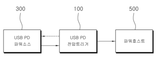
본 발명은 USB PD 타입 전압트리거에 관한 것으로서, SB PD규격에 따른 파워소스와, USB PD규격을 지원하지 않는 파워호스트 사이에 연결되며, 상기 파워호스트의 필요전압에 대한 전압정보를 상기 파워소스로 제공하여 파워소스로부터 상기 필요전압이 파워호스트로 공급되게 하는 것을 특징으로 한다.
이러한 본 발명에 의하면, 전원을 공급하는 파워소스와 전원을 필요로 하는 파워호스트 양쪽 모두의 관점에서 활용성을 크게 향상시킬 수 있는 장점이 있다.The present invention relates to a USB PD type voltage trigger, which is connected between a power source that complies with the SB PD standard and a power host that does not support the USB PD standard, and transmits voltage information about the required voltage of the power host to the power source. It is characterized in that the necessary voltage is supplied from the power source to the power host.
According to the present invention, there is an advantage of greatly improving usability from the perspective of both the power source that supplies power and the power host that requires power.
Description
본 발명은 USB PD 타입 전압트리거에 관한 것으로서, 더욱 상세하게는 USB PD규격에 따른 파워소스로부터 USB PD규격을 지원하지 않는 다양한 파워호스트로 요구되는 필요전압이 원활하게 공급될 수 있게 하는 USB PD 타입 전압트리거에 관한 것이다.The present invention relates to a USB PD type voltage trigger, and more specifically, to a USB PD type that allows the necessary voltage to be smoothly supplied from a power source compliant with the USB PD standard to various power hosts that do not support the USB PD standard. It's about voltage trigger.
USB(Universal Serial Bus)는 기기간 통신을 위한 표준화된 인터페이스로서, 테이터 전송과 전원 공급을 가능하게 하는 USB 인터페이스가 1996년에 처음으로 발표되었으며, 이후 데이터 전송속도와 전원 공급 성능의 향상이 지속적으로 이루어져 왔다.USB (Universal Serial Bus) is a standardized interface for communication between devices. The USB interface, which enables data transfer and power supply, was first announced in 1996. Since then, data transfer speed and power supply performance have continued to improve. come.
예컨대, 1996년에 발표된 USB 1.0 규격은 최대 12Mbp의 데이터 전송 속도를 지원할 수 있었으나, 이후 지속적인 발전을 거듭하여 데이터 전송 성능은 10Gbps까지 발전되기에 이르렀다.For example, the USB 1.0 standard announced in 1996 was able to support data transfer speeds of up to 12Mbps, but since then, continuous development has led to data transfer performance reaching 10Gbps.
한편, USB 규격의 데이터 전송 성능의 향상에도 불구하고, 최대 전력 공급량의 한계로 인하여 USB 방식에 따른 전원 공급의 문제점이 대두됨과 함께 USB의 전력 공급 성능의 향상에 대한 수요가 증가되어 왔다.Meanwhile, despite the improvement in data transmission performance of the USB standard, problems with power supply according to the USB method have emerged due to limitations in maximum power supply, and demand for improvement in USB power supply performance has increased.
이에 따라, USB-IF(USB Implementers Forum)는 2013년에 USB 방식을 이용하여 최대 100W의 전력을 공급할 수 있는 새로운 규격인 USB PD(USB Power Delivery) 규격을 확정하여 발표하였다.Accordingly, USB-IF (USB Implementers Forum) finalized and announced the USB PD (USB Power Delivery) standard in 2013, a new standard that can supply up to 100W of power using the USB method.
이렇게 최대 100W의 전력을 공급할 수 있는 USB PD 규격이 등장함에 따라, 기존의 USB 방식에 따라 전원을 공급할 수 없었던, 예컨대 노트북, 모니터 등과 같이 15V, 20V 등 상대적으로 큰 전압을 필요로 하는 다양한 전자기기들에 대해서도 USB PD 방식의 전원 공급이 가능하게 됨으로써 대응 기기가 대폭 확대되기에 이르렀다.With the advent of the USB PD standard that can supply power of up to 100W, various electronic devices that require relatively large voltages such as 15V, 20V, such as laptops and monitors, that could not be supplied power according to the existing USB method. As USB PD-type power supply became possible for devices, the number of compatible devices has expanded significantly.
그런데, 위와 같이 USB PD 방식으로 전원 공급이 가능한 기기들은 USB PD 규격의 통신이 가능한 구성을 포함하여 새롭게 출시된 기기들로 제한되며, USB PD 규격을 지원하지 않는 기존 기기들의 경우에는 여전히 USB PD 방식의 전원공급이 곤란한 문제점이 있다.However, devices that can supply power using the USB PD method as above are limited to newly released devices including configurations capable of communication in the USB PD standard, and in the case of existing devices that do not support the USB PD standard, the USB PD method is still used. There is a problem with power supply.
즉, 기존에 출시된 노트북, 악기용 앰프 등과 같은 기기들은 USB PD 규격을 지원하지 않으면서 전원 입력포트로서 DC 잭을 갖추고 있기 때문에, USB PD 규격의 전원공급원부터 전원공급을 받을 수 없으며, 여전히 AC/DC 어댑터를 사용하여 전원공급이 이루어져야만 하는 문제점이 있는 것이다.In other words, previously released devices such as laptops and instrument amplifiers do not support the USB PD standard and have a DC jack as a power input port, so they cannot receive power from a USB PD standard power source and still need to be powered by AC. There is a problem that power must be supplied using a /DC adapter.
본 발명은 상술한 종래의 문제점을 해결하기 위하여 제안되는 것으로서, 본 발명의 목적은 USB PD규격에 따른 파워소스로부터 USB PD규격을 지원하지 않는 다양한 파워호스트로 요구되는 필요전압이 원활하게 공급될 수 있게 하는 USB PD 타입 전압트리거를 제공하는 것이다.The present invention is proposed to solve the above-described conventional problems. The purpose of the present invention is to ensure that the required voltage can be smoothly supplied from a power source compliant with the USB PD standard to various power hosts that do not support the USB PD standard. It provides a USB PD type voltage trigger that allows
상기한 목적을 달성하기 위한 본 발명의 과제해결수단으로서,As a means of solving the problems of the present invention to achieve the above-mentioned purpose,
USB PD규격에 따른 파워소스와, USB PD규격을 지원하지 않는 파워호스트 사이에 연결되며, 상기 파워호스트의 필요전압에 대한 전압정보를 상기 파워소스로 제공하여 파워소스로부터 상기 필요전압이 파워호스트로 공급되게 하는, USB PD 타입 전압트리거가 개시된다.It is connected between a power source that complies with the USB PD standard and a power host that does not support the USB PD standard, and provides voltage information about the required voltage of the power host to the power source so that the required voltage can be transferred from the power source to the power host. A USB PD type voltage trigger that causes supply is disclosed.
여기서, 본 발명의 USB PD 타입 전압트리거는, 상기 파워소스와 연결되는 입력포트와, 상기 파워호스트와 연결되는 출력포트와, 사용자로부터 상기 전압정보를 설정받는 트리거스위치와, 상기 설정된 전압정보를 USB PD규격의 통신에 의하여 파워소스로 전송하는 통신부를 포함할 수 있다.Here, the USB PD type voltage trigger of the present invention includes an input port connected to the power source, an output port connected to the power host, a trigger switch that receives the voltage information from the user, and a USB PD type voltage trigger that transmits the set voltage information. It may include a communication unit that transmits to the power source through PD standard communication.
또한, 본 발명의 USB PD 타입 전압트리거는, 사용자로부터 설정되는 상기 전압정보를 표시하는 디스플레이부를 더 포함할 수 있다.Additionally, the USB PD type voltage trigger of the present invention may further include a display unit that displays the voltage information set by the user.
본 발명에 따른 USB PD 타입 전압트리거에 의하면,According to the USB PD type voltage trigger according to the present invention,
USB PD 규격의 파워소스가 USB PD 규격을 지원하는 기기 뿐만 아니라 더 다양한 기기들에 전력을 공급하는 것이 가능해짐과 함께, USB PD 규격을 지원하지 않는 파워호스트의 경우에도 USB PD 규격의 파워소스로부터 원활하게 필요전압을 공급받아 사용될 수 있는 장점이 있다.It is possible for a power source of the USB PD standard to supply power not only to devices that support the USB PD standard, but also to a wider variety of devices, and even in the case of a power host that does not support the USB PD standard, it can be supplied from a power source of the USB PD standard. It has the advantage of being able to be used by smoothly receiving the necessary voltage.
아울러, 상기한 바와 같이 구체적으로 명시한 효과 이외에 본 발명의 특징적인 구성으로부터 용이하게 도출되고 기대될 수 있는 특유한 효과 또한 본 발명의 효과에 포함될 수 있음을 첨언한다.In addition, it is to be added that, in addition to the effects specifically stated above, unique effects that can be easily derived and expected from the characteristic configuration of the present invention may also be included in the effects of the present invention.
도 1은 본 발명의 일 실시예에 따른 USB PD 타입 전압트리거를 일 예시한 도면이며,
도 2는 본 발명의 일 실시예에 따른 USB PD 타입 전압트리거의 세부구성을 일 예시한 도면이고,
도 3은 본 발명의 일 실시예에 따른 USB PD 타입 전압트리거의 사용예를 일 예시한 도면이다.1 is a diagram illustrating a USB PD type voltage trigger according to an embodiment of the present invention.
Figure 2 is a diagram illustrating the detailed configuration of a USB PD type voltage trigger according to an embodiment of the present invention.
Figure 3 is a diagram illustrating an example of use of a USB PD type voltage trigger according to an embodiment of the present invention.
이하, 첨부된 도면들을 참조하여 본 발명에 따른 USB PD 타입 전압트리거에 대한 바람직한 실시예를 상세하게 설명하기로 한다. Hereinafter, a preferred embodiment of the USB PD type voltage trigger according to the present invention will be described in detail with reference to the attached drawings.
본 실시예는 당업계에서 평균적인 지식을 가진 자에게 본 발명을 보다 명확하게 설명하기 위해서 제공되어지는 것으로서, 첨부된 도면에서의 요소의 형상, 크기, 갯수, 요소간의 간격 등은 보다 명확한 설명을 강조하기 위해서 축소되거나 과장되어 표현될 수 있으며, 특별하게 제한하지 않는 한 도면에 예시된 사항으로 한정되지는 않는다.This embodiment is provided to explain the present invention more clearly to those with average knowledge in the art, and the shape, size, number, and spacing between elements of the elements in the attached drawings are provided for a clearer explanation. It may be expressed in a reduced or exaggerated manner for emphasis, and is not limited to the matters illustrated in the drawings unless specifically limited.
또한, 실시예를 설명하는데 있어서, 만일 어떤 구성요소가 다른 구성요소에 “구비되어”, “형성되어”, “설치되어”, “결합되어”, “고정되어”, “연결되어” 있다고 기재된 때에는, 그 다른 구성요소에 직접적으로 구비, 형성, 설치, 결합, 고정, 연결되어 있을 수도 있지만, 중간에 다른 구성요소가 존재할 수도 있다고 이해되어야 할 것이다.Additionally, when describing an embodiment, if a component is described as being “provided,” “formed,” “installed,” “coupled,” “fixed,” or “connected” to another component, , it may be directly provided, formed, installed, combined, fixed, or connected to other components, but it should be understood that other components may exist in the middle.
또한, 전, 후, 좌, 우, 상, 하 등과 같은 방향을 나타내는 용어들은, 도면에 도시되고 관측되는 방향을 설명하기 위해 사용되었을 뿐, 도시되고 관측되는 방향이 달라지면 이 같은 용어들 역시 달라질 수 있음이 이해되어야 할 것이다.In addition, terms indicating directions such as front, back, left, right, up, down, etc. are only used to describe the direction shown and observed in the drawing, and these terms may also change if the shown and observed direction changes. It must be understood that it exists.
아울러, 실시예를 설명하는데 있어서 원칙적으로 관련된 공지의 기능이나 공지의 구성과 같이 이미 당해 기술분야의 통상의 기술자에게 자명한 사항으로서 본 발명의 기술적 특징을 불필요하게 흐릴 수 있다고 판단되는 경우에는 그 상세한 설명을 생략하기로 한다.In addition, when describing the embodiments, in principle, if it is determined that matters already obvious to those skilled in the art, such as related known functions or known configurations, may unnecessarily obscure the technical features of the present invention, We will omit the explanation.
본 발명은 USB PD규격에 따른 파워소스와, USB PD규격을 지원하지 않는 파워호스트 사이에 연결 설치되어, 상기 파워호스트의 필요전압에 대한 전압정보를 상기 파워소스로 제공함으로써 파워소스로부터 상기 필요전압이 파워호스트로 공급될 수 있게 하는 USB PD 타입 전압트리거에 관한 것이다.The present invention is connected and installed between a power source that complies with the USB PD standard and a power host that does not support the USB PD standard, and provides voltage information about the required voltage of the power host to the power source to obtain the required voltage from the power source. This concerns a USB PD type voltage trigger that can be supplied to the power host.
즉, USB PD규격에 따른 파워소스로부터 전원공급을 받을 수 없는 다양한 파워호스트의 경우에도 본 발명의 USB PD 타입 전압트리거를 통하여 간편하게 USB PD규격에 따른 파워소스로부터 전원공급을 원활하게 공급받을 수 있게 되는 것이다.In other words, even in the case of various power hosts that cannot receive power supply from a power source compliant with the USB PD standard, they can easily and smoothly receive power supply from a power source compliant with the USB PD standard through the USB PD type voltage trigger of the present invention. It will happen.
이를 위한 본 발명의 일 실시예에 따른 USB PD 타입 전압트리거가 도 1 내지 도 3에 일 예시되어 있다.For this purpose, a USB PD type voltage trigger according to an embodiment of the present invention is illustrated in FIGS. 1 to 3.
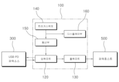
상기 도면들에 일 예시되어 있는 것처럼, 본 발명의 일 실시예에 따른 USB PD 타입 전압트리거(100, 이하, “전압트리거”라 약칭함.)는 하우징(110)과, 입력포트(120)와, 출력포트(130)와, 트리거스위치(140)와, 통신부(150)와, 디스플레이부(160)를 포함하여 구성될 수 있다.As illustrated in the drawings, the USB PD type voltage trigger 100 (hereinafter abbreviated as “voltage trigger”) according to an embodiment of the present invention includes a
상기 하우징(110)은 본 발명에 따른 전압트리거(100)의 외관을 구성하는 것으로서, 다른 구성요소들은 상기 하우징(110)의 내부에 수용되거나 외부로 노출되도록 설치될 수 있다.The
상기 하우징(110)은 휴대가 가능한 크기로 이루어질 수 있으며, 도면에 일 예시된 것처럼 직육면체 형상을 가질 수 있는데, 이에 한정되지는 않으며, 다양한 형상으로 구현되는 것이 물론 가능하다.The
상기 입력포트(120)는 파워소소(300, Power Source Device)와 연결되는 부분으로서, 본 발명의 전압트리거(100)는 입력포트(120)를 통해 파워소스(300)와 USB PD 통신 신호를 송수신함과 함께, 파워소스(300)로부터 제공되는 전력을 수신할 수 있다.The
이러한 입력포트(120)는 바람직하게는 USB Type-C Plug 또는 USB Type-C Receptacle로 형성될 수 있으나, 이에 한정되지는 않는다.This
USB Type-C Plug인 경우 본 발명의 전압트리거(100)를 파워소스(300)와 다이렉트로 연결할 경우에 유용하며, USB Type-C Receptacle인 경우에는 본 발명의 전압트리거(100)와 파워소스(300) 사이에 USB-C 케이블을 연결하여 기기간의 거리를 확보할 필요성이 있을 때 보다 유용할 수 있다.In the case of a USB Type-C Plug, it is useful when connecting the voltage trigger (100) of the present invention directly with the power source (300), and in the case of a USB Type-C Receptacle, the voltage trigger (100) of the present invention and the power source (300) are used. 300), it can be more useful when there is a need to secure the distance between devices by connecting a USB-C cable.
여기서, 입력포트(120)가 접속 연결되는 상기 파워소스(300)는 USB PD 규격에 따른 전원공급원으로서, USB PD 규격을 지원하는 보조배터리 또는 USB PD 규격을 지원하는 AC/DC 아답터 등이 제한없이 포함될 수 있다.Here, the
상기 파워소스(300)는 본 발명에 따른 전압트리거(100)의 입력포트(120)에 USB Type-C 커넥터 또는 USB 케이블로 연결될 수 있으며, USB PD 프로토콜(Protocol)에 따라 본 발명의 전압트리거(100)와 통신하여 요구된 전력을 전달할 수 있는 조건을 확인한 후 전압트리거(100)를 통하여 파워호스트(500)로 요구되는 전력을 공급하게 된다.The
상기 출력포트(130)는 파워호스트(500, Power Host Device)와 연결되는 부분으로서, 본 발명의 전압트리거(100)는 파워소스(300)로부터 수신된 전력을 출력포트(130)를 통해 파워호스트(500)로 출력하여 공급할 수 있다.The
출력포트(130)는 DC Plug로 형성되어 파워호스트(500)와 직결되거나 케이블을 통하여 연결될 수 있다.The
여기서, 상기 출력포트(130)가 접속 연결되는 상기 파워호스트(500)는 USB PD 규격을 지원하지 않는, 즉 전원공급원으로 AC/DC Adapter를 사용하는 다양한 전자기기들을 의미할 수 있다.Here, the
예를 들어, 파워호스트(500)는 전원공급원으로 AC/DC Adapter를 사용하는 노트북, 모니터, 악기용 앰프, 전자기타용 이펙터, 블루투스 앰프/스피커 등 특별하게 제한됨이 없이 다양한 전자기기들이 포함될 수 있다.For example, the
파워호스트(500)는 전원입력포트로 DC Jack을 가짐으로써 전압트리거(100)의 DC Plug와 연결될 수 있으며, 필요에 따라 연장 케이블을 사용하거나 Jack의 크기 및 극성을 고려하여 변환 젠더를 사용할 수도 있다The Power Host (500) has a DC Jack as a power input port and can be connected to the DC Plug of the voltage trigger (100). If necessary, an extension cable can be used or a conversion gender can be used considering the size and polarity of the Jack.
상기한 입력포트(120)와 출력포트(130)는 도 3에 일 예시된 것처럼 하우징(110)의 좌우 측면에 대칭구조를 이루어 각각 형성될 수 있다. 다만, 반드시 이에 한정되지는 않으며 입력포트(120)와 출력포트(130)의 형성 위치는 필요에 따라 다양하게 설정될 수 있다.The
상기 트리거스위치(140)는 사용자로부터 파워호스트(500)의 필요전압에 대한 전압정보를 설정 입력받는 부분이다.The
본 발명의 전압트리거(100)와 연결되는 파워호스트(500)는 기기 종류에 따라 다양한 필요전압이 요구될 수 있으며, 사용자는 이러한 파워호스트(500)의 필요전압을 트리거스위치(140)를 통해 입력 설정할 수 있다.The
즉, 본 발명의 전압트리거(100)가 연결되는 파워호스트(500)는 USB PD 규격을 지원하지 않기 때문에 자체적으로는 USB PD 규격의 통신이 불가능하며, 따라서 파워호스트(500)의 필요전압에 대한 전압정보는 트리거스위치(140)를 통해 사용자가 수동으로 설정하게 되는 것이다.That is, since the
이렇게 사용자로부터 트리거스위치(140)를 통하여 설정된 필요전압의 전압정보는 후술하는 통신부(150)로 제공될 수 있다.In this way, the voltage information of the required voltage set by the user through the
예를 들어, 본 발명의 전압트리거(100)가 연결된 파워호스트(500)의 필요전압이 15V인 경우 사용자는 트리거스위치(140)를 15V로 선택하여 필요전압을 설정할 수 있고, 파워호스트(500)의 필요전압이 20V인 경우 트리거스위치(140)를 20V로 조절하여 필요전압을 설정할 수 있는 것이며, 이렇게 설정된 필요전압 15V 또는 20V에 대한 전압정보가 통신부(150)로 전달되는 것이다.For example, if the required voltage of the
상기 통신부(150)는 파워소스(300)와 USB PD 규격의 통신을 수행하여 필요전압에 대한 전압정보를 파워소스(300)로 전달하는 부분이다.The
즉, 통신부(150)는 파워소스(300)와 통신이 가능한 USB PD 프로토콜 칩(IC)을 포함하며, 트리거스위치(140)를 통해 설정된 전압정보를 파워소스(300)로 전송하도록 파워소스(300)와 USB PD 규격의 통신을 수행하게 된다.That is, the
상기 디스플레이부(160)는 사용자로부터 설정되는 상기 전압정보를 사용자가 인식할 수 있도록 표시하는 부분이다.The
즉, 사용자는 디스플레이부(160)를 통해 표시되는 정보를 통하여 필요전압이 얼마로 설정되어 있는지를 쉽게 확인할 수 있다.In other words, the user can easily check how much the required voltage is set through the information displayed through the
이러한 디스플레이부(160)는 예를 들어, 소형화 및 단순화를 위하여 상이한 색상을 갖는 복수의 LED(Multi Color LED)로 구성되거나, 시인성의 향상을 위하여 구체적으로 문자화된 정보를 표시할 수 있는 디스플레이 패널(LED Display Panel)로 구성될 수 있다.For example, the
이상으로 본 발명의 일 실시예를 설명하였는 바, 이하에서는 그 작용에 대하여 간략하게 살펴본다.Having described an embodiment of the present invention above, its operation will be briefly discussed below.
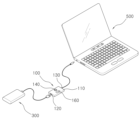
도 3에 일 예시된 것처럼, USB PD 규격에 따른 파워소스(300), 예컨대 보조배터리가 있고, USB PD 규격을 지원하지 않는 파워호스트(500), 예컨대 노트북을 사용한다고 가정한다.As illustrated in FIG. 3, it is assumed that there is a
상기 노트북은 USB PD 규격을 지원하지 않으면서 DC Jack이 전원입력포트로서 구비되어 있기 때문에, 상기 USB PD 규격의 보조배터리를 전원공급원으로 이용하여 노트북을 사용할 수는 없게 된다.Since the laptop does not support the USB PD standard and is equipped with a DC jack as a power input port, the laptop cannot be used using an auxiliary battery that complies with the USB PD standard as a power supply source.
이 때, 본 발명의 전압트리거(100)를 사용하면 USB PD 규격의 보조배터리를 전원공급원으로 이용하여 노트북을 사용할 수 있게 된다.At this time, by using the
먼저, 전압트리거(100)의 입력포트(120)를 USB PD 규격의 보조배터리와 연결시키고 출력포트(130)를 노트북과 연결시켜 보조배터리와 노트북 사이에 본 발명의 전압트리거(100)를 연결 설치한다.First, the
이 때, 보조배터리와 입력포트(120)는 USB 직결방식으로 연결되거나 USB 케이블을 통해 연결될 수 있으며, 출력포트(130)는 DC Plug를 노트북의 DC Jack에 끼워 연결할 수 있다.At this time, the auxiliary battery and the
이렇게 파워소스(300)인 보조배터리와 파워호스트(500)인 노트북 사이에 본 발명의 전압트리거(100)가 연결 설치되면, 사용자는 노트북이 요구하는 필요전압을 확인한 후 이에 맞추어 트리거스위치(140)를 선택하여 필요전압을 설정 입력하면 된다.When the
이 때, 사용자가 선택하는 필요전압에 대한 전압정보는 디스플레이부(160)를 통하여 표시되므로 사용자는 표시되는 정보를 확인하면서 쉽고 정확하게 필요전압을 설정 입력할 수 있게 된다.At this time, the voltage information for the required voltage selected by the user is displayed through the
위와 같이 트리거스위치(140)를 통해 필요전압이 설정되면 이러한 전압정보는 통신부(150)로 제공되고, 통신부(150)는 보조배터리와 USB PD 규격의 통신을 수행하여 설정된 전압정보를 보조배터리로 전달하게 된다.When the required voltage is set through the
그러면, 보조배터리는 USB PD 규격에 따른 파워호스트로 전원을 공급하는 것과 동일하게, 수신된 전압정보에 따라 필요전압을 노트북으로 공급하게 되며, 따라서 USB PD 규격을 지원하지 않는 노트북임에도 불구하고 간편하게 USBP PD 규격의 보조배터리로부터 전원을 공급받아 용이하게 사용할 수 있게 되는 것이다.Then, the auxiliary battery supplies the necessary voltage to the laptop according to the received voltage information, just as it supplies power to the power host according to the USB PD standard. Therefore, even though the laptop does not support the USB PD standard, it can be easily connected to USBP. It can be easily used by receiving power from a PD standard auxiliary battery.
이상에서 살펴본 것처럼, 본 발명에 따른 전압트리거에 의하면, USB PD 규격의 파워소스가 USB PD 규격을 지원하는 기기 뿐만 아니라 더 다양한 기기들에 전력을 공급하는 것이 가능하도록 해줄 수 있다.As seen above, according to the voltage trigger according to the present invention, a USB PD standard power source can supply power to a wider variety of devices as well as devices that support the USB PD standard.
다른 관점에서 보면, 본 발명에 따른 전압트리거는, USB PD 규격을 지원하지 않는 파워호스트의 경우에도 USB PD 규격의 파워소스로부터 원활하게 필요전압을 공급받아 사용될 수 있게 되며, 따라서 야외 등과 같이 AC 콘센트가 없는 다양한 곳에서도 원활하게 전력을 확보할 수 있게 된다.From another perspective, the voltage trigger according to the present invention can be used by smoothly receiving the necessary voltage from a power source of the USB PD standard even in the case of a power host that does not support the USB PD standard, and therefore can be used in an AC outlet such as outdoors. You will be able to secure power smoothly even in various places where there is no electricity.
결국, 본 발명의 전압트리거는, 전원을 공급하는 파워소스와 전원을 필요로 하는 파워호스트 양쪽 모두의 관점에서 활용성을 크게 향상시킬 수 있음과 함께, In-dorr 기기를 Out-door 기기처럼 편리하게 사용할 수 있는 편의성도 제공할 수 있음을 알 수 있다.Ultimately, the voltage trigger of the present invention can greatly improve usability from the perspective of both the power source that supplies power and the power host that requires power, and it is also convenient to use in-dorr devices as outdoor devices. It can be seen that it can also provide convenience for easy use.
이상으로 본 발명의 바람직한 실시예를 상세하게 설명하였는데, 본 발명의 기술적 범위는 상술한 실시예 및 도면들에 기재된 내용으로 한정되는 것은 아니며, 해당 기술분야의 통상의 지식을 가진 자에 의해 수정 또는 변경된 등가의 구성은 본 발명의 기술적 사상의 범위를 벗어나지 않는 것이라 할 것이다.Preferred embodiments of the present invention have been described in detail above, but the technical scope of the present invention is not limited to the content described in the above-described embodiments and drawings, and can be modified or modified by those skilled in the art. It will be said that the changed equivalent configuration does not deviate from the scope of the technical idea of the present invention.
첨부된 도면들의 주요부위에 대한 부호를 설명하면 다음과 같다.
100: 전압트리거
110: 하우징
120: 입력포트
130: 출력포트
140: 트리거스위치
150: 통신부
160: 디스플레이부
300: 파워소스
500: 파워호스트The symbols for major parts in the attached drawings are explained as follows.
100: Voltage trigger
110: housing 120: input port
130: output port 140: trigger switch
150: Communication unit 160: Display unit
300: Power source
500: Powerhost
Claims (3)
상기 파워호스트의 필요전압에 대한 전압정보를 상기 파워소스로 제공하여 파워소스로부터 상기 필요전압이 파워호스트로 공급되게 하는, USB PD 타입 전압트리거.It is connected between a power source that complies with the USB PD standard and a power host that does not support the USB PD standard.
A USB PD type voltage trigger that provides voltage information about the required voltage of the power host to the power source so that the required voltage is supplied from the power source to the power host.
상기 파워소스와 연결되는 입력포트와;
상기 파워호스트와 연결되는 출력포트와;
사용자로부터 상기 전압정보를 설정받는 트리거스위치와;
상기 설정된 전압정보를 USB PD규격의 통신에 의하여 파워소스로 전송하는 통신부를 포함하는, USB PD 타입 전압트리거.According to clause 1,
an input port connected to the power source;
an output port connected to the power host;
a trigger switch that receives the voltage information from the user;
A USB PD type voltage trigger including a communication unit that transmits the set voltage information to a power source through communication of the USB PD standard.
사용자로부터 설정되는 상기 전압정보를 표시하는 디스플레이부;를 더 포함하는, USB PD 타입 전압트리거.According to clause 2,
A USB PD type voltage trigger, further comprising a display unit that displays the voltage information set by the user.
Priority Applications (1)
| Application Number | Priority Date | Filing Date | Title |
|---|---|---|---|
| KR1020220045099A KR20230146292A (en) | 2022-04-12 | 2022-04-12 | USB PD Voltage Trigger |
Applications Claiming Priority (1)
| Application Number | Priority Date | Filing Date | Title |
|---|---|---|---|
| KR1020220045099A KR20230146292A (en) | 2022-04-12 | 2022-04-12 | USB PD Voltage Trigger |
Publications (1)
| Publication Number | Publication Date |
|---|---|
| KR20230146292A true KR20230146292A (en) | 2023-10-19 |
Family
ID=88507868
Family Applications (1)
| Application Number | Title | Priority Date | Filing Date |
|---|---|---|---|
| KR1020220045099A KR20230146292A (en) | 2022-04-12 | 2022-04-12 | USB PD Voltage Trigger |
Country Status (1)
| Country | Link |
|---|---|
| KR (1) | KR20230146292A (en) |
Citations (1)
| Publication number | Priority date | Publication date | Assignee | Title |
|---|---|---|---|---|
| KR20190005643A (en) | 2017-07-07 | 2019-01-16 | 삼성전자주식회사 | Electronic device supporting usb power delivery standard and a method of charging the electronic device |
-
2022
- 2022-04-12 KR KR1020220045099A patent/KR20230146292A/en not_active Application Discontinuation
Patent Citations (1)
| Publication number | Priority date | Publication date | Assignee | Title |
|---|---|---|---|---|
| KR20190005643A (en) | 2017-07-07 | 2019-01-16 | 삼성전자주식회사 | Electronic device supporting usb power delivery standard and a method of charging the electronic device |
Similar Documents
| Publication | Publication Date | Title |
|---|---|---|
| JP3979300B2 (en) | Interface module for digital video signal transmission | |
| US8794997B2 (en) | Wall outlet type USB hub with independent charging function | |
| US20180165053A1 (en) | Docking station with dual-display synchronous output | |
| US20090153536A1 (en) | Receiving module and signal transmitting apparatus using the same | |
| EP3343907B1 (en) | Television mainboard device, connection device, television, and television system | |
| US10474204B2 (en) | Electrical power supply expansion card and computer case | |
| CN101567177A (en) | Display apparatus and a method for supplying power thereto | |
| KR20030036364A (en) | Structure for modular computer | |
| US20120096286A1 (en) | Charging management method, charging control circuit and the host apparatus having the same | |
| US7722406B2 (en) | Output adapting device of plug-in power system | |
| CN107579402A (en) | A kind of VR/AR connection cables | |
| US20130022320A1 (en) | Universal modular connector | |
| KR20230146292A (en) | USB PD Voltage Trigger | |
| JP2008228041A (en) | Signal transmitter and transmission module | |
| CN217405088U (en) | Display circuit and display device | |
| JP4345652B2 (en) | Digital video signal interface module | |
| CN212659070U (en) | Adapter | |
| CN217008117U (en) | Upgradable all-in-one | |
| US20070139295A1 (en) | Extra-monitor control circuit system for monitor | |
| CN220935246U (en) | HDMI optical fiber signal transmission cable, HDMI receiving equipment and video matrix switch | |
| CN218630761U (en) | Double-blind insertion handwriting device | |
| CN218896913U (en) | Multifunctional connecting wire, display screen and display device | |
| CN204462951U (en) | The integrated display of built-in prolongation receiver function | |
| CN211319323U (en) | Control device for self-lifting cabinet and self-lifting cabinet | |
| CN219997567U (en) | Type-C docking station supporting multi-host connection and system thereof |
Legal Events
| Date | Code | Title | Description |
|---|---|---|---|
| E902 | Notification of reason for refusal |