KR20230140887A - Fuel control device using electrochemical compressor - Google Patents
Fuel control device using electrochemical compressor Download PDFInfo
- Publication number
- KR20230140887A KR20230140887A KR1020220039700A KR20220039700A KR20230140887A KR 20230140887 A KR20230140887 A KR 20230140887A KR 1020220039700 A KR1020220039700 A KR 1020220039700A KR 20220039700 A KR20220039700 A KR 20220039700A KR 20230140887 A KR20230140887 A KR 20230140887A
- Authority
- KR
- South Korea
- Prior art keywords
- hydrogen
- fuel
- tank
- electrochemical
- space
- Prior art date
- Legal status (The legal status is an assumption and is not a legal conclusion. Google has not performed a legal analysis and makes no representation as to the accuracy of the status listed.)
- Granted
Links
Images




Classifications
-
- C—CHEMISTRY; METALLURGY
- C01—INORGANIC CHEMISTRY
- C01B—NON-METALLIC ELEMENTS; COMPOUNDS THEREOF; METALLOIDS OR COMPOUNDS THEREOF NOT COVERED BY SUBCLASS C01C
- C01B3/00—Hydrogen; Gaseous mixtures containing hydrogen; Separation of hydrogen from mixtures containing it; Purification of hydrogen; Reversible storage of hydrogen
- C01B3/50—Separation of hydrogen or hydrogen-containing gases from gaseous mixtures, e.g. purification
-
- B—PERFORMING OPERATIONS; TRANSPORTING
- B01—PHYSICAL OR CHEMICAL PROCESSES OR APPARATUS IN GENERAL
- B01D—SEPARATION
- B01D53/00—Separation of gases or vapours; Recovering vapours of volatile solvents from gases; Chemical or biological purification of waste gases, e.g. engine exhaust gases, smoke, fumes, flue gases, aerosols
- B01D53/32—Separation of gases or vapours; Recovering vapours of volatile solvents from gases; Chemical or biological purification of waste gases, e.g. engine exhaust gases, smoke, fumes, flue gases, aerosols by electrical effects other than those provided for in group B01D61/00
- B01D53/326—Separation of gases or vapours; Recovering vapours of volatile solvents from gases; Chemical or biological purification of waste gases, e.g. engine exhaust gases, smoke, fumes, flue gases, aerosols by electrical effects other than those provided for in group B01D61/00 in electrochemical cells
-
- C—CHEMISTRY; METALLURGY
- C01—INORGANIC CHEMISTRY
- C01B—NON-METALLIC ELEMENTS; COMPOUNDS THEREOF; METALLOIDS OR COMPOUNDS THEREOF NOT COVERED BY SUBCLASS C01C
- C01B3/00—Hydrogen; Gaseous mixtures containing hydrogen; Separation of hydrogen from mixtures containing it; Purification of hydrogen; Reversible storage of hydrogen
- C01B3/50—Separation of hydrogen or hydrogen-containing gases from gaseous mixtures, e.g. purification
- C01B3/501—Separation of hydrogen or hydrogen-containing gases from gaseous mixtures, e.g. purification by diffusion
- C01B3/503—Separation of hydrogen or hydrogen-containing gases from gaseous mixtures, e.g. purification by diffusion characterised by membranes
-
- F—MECHANICAL ENGINEERING; LIGHTING; HEATING; WEAPONS; BLASTING
- F02—COMBUSTION ENGINES; HOT-GAS OR COMBUSTION-PRODUCT ENGINE PLANTS
- F02K—JET-PROPULSION PLANTS
- F02K9/00—Rocket-engine plants, i.e. plants carrying both fuel and oxidant therefor; Control thereof
- F02K9/42—Rocket-engine plants, i.e. plants carrying both fuel and oxidant therefor; Control thereof using liquid or gaseous propellants
- F02K9/44—Feeding propellants
- F02K9/50—Feeding propellants using pressurised fluid to pressurise the propellants
-
- F—MECHANICAL ENGINEERING; LIGHTING; HEATING; WEAPONS; BLASTING
- F02—COMBUSTION ENGINES; HOT-GAS OR COMBUSTION-PRODUCT ENGINE PLANTS
- F02K—JET-PROPULSION PLANTS
- F02K9/00—Rocket-engine plants, i.e. plants carrying both fuel and oxidant therefor; Control thereof
- F02K9/42—Rocket-engine plants, i.e. plants carrying both fuel and oxidant therefor; Control thereof using liquid or gaseous propellants
- F02K9/44—Feeding propellants
- F02K9/56—Control
-
- F—MECHANICAL ENGINEERING; LIGHTING; HEATING; WEAPONS; BLASTING
- F02—COMBUSTION ENGINES; HOT-GAS OR COMBUSTION-PRODUCT ENGINE PLANTS
- F02K—JET-PROPULSION PLANTS
- F02K9/00—Rocket-engine plants, i.e. plants carrying both fuel and oxidant therefor; Control thereof
- F02K9/42—Rocket-engine plants, i.e. plants carrying both fuel and oxidant therefor; Control thereof using liquid or gaseous propellants
- F02K9/60—Constructional parts; Details not otherwise provided for
- F02K9/605—Reservoirs
-
- C—CHEMISTRY; METALLURGY
- C01—INORGANIC CHEMISTRY
- C01B—NON-METALLIC ELEMENTS; COMPOUNDS THEREOF; METALLOIDS OR COMPOUNDS THEREOF NOT COVERED BY SUBCLASS C01C
- C01B2203/00—Integrated processes for the production of hydrogen or synthesis gas
- C01B2203/04—Integrated processes for the production of hydrogen or synthesis gas containing a purification step for the hydrogen or the synthesis gas
- C01B2203/0405—Purification by membrane separation
Landscapes
- Engineering & Computer Science (AREA)
- Chemical & Material Sciences (AREA)
- Combustion & Propulsion (AREA)
- Organic Chemistry (AREA)
- Mechanical Engineering (AREA)
- General Engineering & Computer Science (AREA)
- Inorganic Chemistry (AREA)
- Analytical Chemistry (AREA)
- Oil, Petroleum & Natural Gas (AREA)
- Chemical Kinetics & Catalysis (AREA)
- General Chemical & Material Sciences (AREA)
- Electrochemistry (AREA)
- Fuel Cell (AREA)
Abstract
Description
본 발명은 전기화학적 수소 압축기를 이용한 연료제어 장치에 관한 것으로, 더욱 상세하게는 전기화학적 수소 압축기를 이용하여 우주 발사체에서 사용되는 액체 연료의 압력과 유량을 정밀하게 제어할 수 있도록, 구조가 개선된 전기화학적 수소 압축기를 이용한 연료제어 장치에 관한 것이다. The present invention relates to a fuel control device using an electrochemical hydrogen compressor. More specifically, the present invention relates to an improved structure so that the pressure and flow rate of liquid fuel used in a space launch vehicle can be precisely controlled using an electrochemical hydrogen compressor. This relates to a fuel control device using an electrochemical hydrogen compressor.
현재 전 세계적으로 우주 탐사에 대한 관심이 높아지고 있다. 이에 따라 여러 국가들뿐만 아니라 민감 기업에서도 우주 탐사를 위해 많은 연구와 기술개발이 진행되고 있다. 우주 탐사를 위해서 사용되는 우주 발사체는 균일한 압력과 유량으로 연료를 연소시키기 위해, 고체 연료를 많이 사용하고 있다. 하지만 고체 연료의 사용 시 연료가 모두 소모될 때까지 연소되기 때문에 그 연료의 압력과 유량을 정밀하게 제어하기 어렵다. 이러한 단점을 개선하기 위해 액체 연료를 사용하는 우주 발사체의 개발도 다양하게 이루어지고 있다. Currently, interest in space exploration is increasing worldwide. Accordingly, a lot of research and technology development is being conducted for space exploration not only in many countries but also in sensitive companies. Space launch vehicles used for space exploration use a lot of solid fuel to burn fuel at uniform pressure and flow rate. However, when solid fuel is used, it is difficult to precisely control the pressure and flow rate of the fuel because it burns until all of the fuel is consumed. To improve these shortcomings, various space launch vehicles using liquid fuel are being developed.
우주 발사체에 액체 연료를 사용할 경우, 연료 제어의 높은 정밀성과 추진력을 얻을 수 있고 연료의 재사용이 가능한 장점을 갖는다. 그러나 우주 발사체가 우주에 있을 때는 중력이 균일하지 않음으로써, 연료 탱크에서 그 액체 연료를 원하는 압력과 유량으로 제어할 수 없다는 단점을 가진다. When liquid fuel is used in a space launch vehicle, high precision and propulsion can be achieved in fuel control, and the fuel can be reused. However, when a space launch vehicle is in space, gravity is not uniform, so it has the disadvantage of not being able to control the liquid fuel in the fuel tank to the desired pressure and flow rate.
따라서, 연료 탱크를 원하는 압력으로 유지할 수 있도록 하고 액체 연료의 압력뿐만 아니라 유량을 정밀하게 제어할 수 있도록 하며, 액체 연료의 공급 시 맥동 유동을 방지하면서 강한 추진력을 얻을 수 있도록 하는 연료제어 기술이 요구되고 있다. Therefore, fuel control technology is required to maintain the fuel tank at the desired pressure, to precisely control the flow rate as well as the pressure of the liquid fuel, and to obtain strong propulsion while preventing pulsation flow when supplying liquid fuel. It is becoming.
종래기술로는 공개특허공보 제10-2006-0060435호가 있다. The prior art includes Patent Publication No. 10-2006-0060435.
본 발명은 상기와 같은 문제점을 해결하기 위해 안출된 것으로, 본 발명의 목적은 우주 발사체에 사용되는 액체 연료의 압력과 유량 정밀하게 제어할 수 있도록 하고, 연료 탱크를 원하는 압력으로 유지시킬 수 있으며 액체 연료의 공급 시 맥동 유동을 방지하면서 고체 연료에 비해 장거리 추진을 가능하게 하며 강한 추진력을 얻을 수 있도록 하는, 전기화학적 수소 압축기를 이용한 연료제어 장치를 제공하고자 하는 것이다. The present invention was created to solve the above problems, and the purpose of the present invention is to precisely control the pressure and flow rate of liquid fuel used in space launch vehicles, to maintain the fuel tank at the desired pressure, and to maintain the liquid fuel tank at the desired pressure. The goal is to provide a fuel control device using an electrochemical hydrogen compressor that prevents pulsating flow when supplying fuel, enables long-distance propulsion and obtains strong propulsion compared to solid fuel.
본 발명의 해결과제는 이상에서 언급된 것들에 한정되지 않으며, 언급되지 아니한 다른 해결과제들은 아래의 기재로부터 당업자에게 명확하게 이해되어 질 수 있을 것이다.The problems to be solved by the present invention are not limited to those mentioned above, and other problems not mentioned can be clearly understood by those skilled in the art from the description below.
상기 목적을 달성하기 위한 본 발명의 일실시예에 의한 전기화학적 수소 압축기를 이용한 연료제어 장치는, 수소의 이동 경로 상에 배치되어, 전압 인가에 따른 산화 환원 반응에 의해 수소를 압축된 상태로 이동시킬 수 있게 하는 막전극 접합체를 포함한 전기화학적 수소 압축기; 및, 연료가 저장되는 연료 탱크와, 상기 연료 탱크 내에 이동 가능하게 설치되고 그 연료 탱크 내의 공간을 연료가 저장되는 연료저장공간과 수소가 유입되는 수소유입공간(전기화학적 수소 압축기의 토출구와 연결)으로 분할되게 배치되는 것으로, 상기 수소유입공간으로 유입된 수소 압력에 의해 연료저장공간 측으로 이동되어 그 연료저장공간에 수용되어 있는 연료를 가압하여 토출시킬 수 있게 하는 가압디스크를 구비하는 연료 분사 유닛;을 포함하여 이루어진다.In order to achieve the above object, a fuel control device using an electrochemical hydrogen compressor according to an embodiment of the present invention is disposed on the hydrogen movement path and moves hydrogen in a compressed state by an oxidation-reduction reaction according to the application of voltage. An electrochemical hydrogen compressor including a membrane electrode assembly that enables And, a fuel tank in which fuel is stored, movably installed within the fuel tank, and the space within the fuel tank is divided into a fuel storage space in which fuel is stored and a hydrogen inlet space in which hydrogen flows (connected to the discharge port of the electrochemical hydrogen compressor). A fuel injection unit arranged to be divided into a fuel injection unit that is moved toward the fuel storage space by the pressure of hydrogen flowing into the hydrogen inflow space and has a pressurizing disk that pressurizes and discharges the fuel contained in the fuel storage space; It is made including.
상기 연료 분사 유닛은, 일측은 상기 연료 탱크의 중심부를 관통하여 상기 가압디스크에 연결되고, 타측은 연료 탱크의 외부로 노출되는 연결로드;를 포함하여 이루어지는 것이 바람직하다. The fuel injection unit preferably includes a connecting rod, one side of which penetrates the center of the fuel tank and is connected to the pressurizing disk, and the other side of which is exposed to the outside of the fuel tank.
본 발명의 다른 실시예에 의한 전기화학적 수소 압축기를 이용한 연료제어 장치는, 수소의 이동 경로 상에 배치되어, 전압 인가에 따른 산화 환원 반응에 의해 수소를 압축된 상태로 이동시킬 수 있게 하는 막전극 접합체를 포함한 전기화학적 수소 압축기; 및, 연료가 저장되는 연료 탱크와, 전기화학적 수소 압축기의 토출구와 연결되어서 수소가 유입되는 수소 유입 탱크와, 상기 연료 탱크 내에 이동 가능하게 설치되고 그 연료 탱크 내의 공간이 2분할되도록 배치되는 연료측 디스크와, 상기 수소 유입 탱크 내에 이동 가능하게 설치되고 그 수소 유입 탱크 내의 공간이 2분할되도록 배치되는 수소측 디스크와, 일측은 상기 연료 탱크를 관통하여 연료측 디스크에 연결되고 타측은 상기 수소 유입 탱크를 관통하여 상기 수소측 디스크에 연결되어서 연료측 디스크와 수소측 디스크를 함께 이동될 수 있게 하는 연결로드를 구비하는 연료 분사 유닛;을 포함하여 이루어져서, 상기 수소 유입 탱크 내부로 유입된 수소 압력에 의해 상기 수소측 디스크가 가압되어서 연료측 디스크와 함께 이동되어서 상기 연료 탱크에 수용되어 있는 연료를 가압하여 토출되게 하고, 연료가 유입되는 공간과 수소가 유입되는 공간을 연료 탱크와 수소 유입 탱크로 각각 별도로 형성하는 것에 의해 서로 섞이지 않게 함으로써 수소와 연료 간의 반응을 방지할 수 있게 한다. A fuel control device using an electrochemical hydrogen compressor according to another embodiment of the present invention includes a membrane electrode disposed on the hydrogen movement path to move hydrogen in a compressed state through an oxidation-reduction reaction according to the application of voltage. Electrochemical hydrogen compressor including conjugate; and a fuel tank in which fuel is stored, a hydrogen inflow tank connected to the discharge port of the electrochemical hydrogen compressor into which hydrogen flows, and a fuel side that is movably installed in the fuel tank and arranged so that the space in the fuel tank is divided into two. A disk, a hydrogen side disk that is movably installed in the hydrogen inlet tank and arranged so that the space in the hydrogen inlet tank is divided into two, one side penetrates the fuel tank and is connected to the fuel side disk, and the other side is connected to the hydrogen inlet tank. A fuel injection unit having a connecting rod that penetrates and is connected to the hydrogen side disk so that the fuel side disk and the hydrogen side disk can be moved together, by the pressure of hydrogen flowing into the hydrogen introduction tank. The hydrogen side disk is pressurized and moves together with the fuel side disk to pressurize and discharge the fuel contained in the fuel tank, and the space into which the fuel flows and the space into which the hydrogen flows are separately divided into a fuel tank and a hydrogen inlet tank. By forming them so they do not mix together, it is possible to prevent a reaction between hydrogen and fuel.
상기 전기화학적 수소 압축기는, 각각 수소가 이동할 수 있는 수소이동로가 형성되어 있고, 동일한 축선 상에 간격을 두고 서로 대향 배치되는 한 쌍의 분리판들; 상기 한 쌍의 분리판들 중 어느 하나를 통과한 수소의 이동 경로 상에 배치되어, 전압 인가에 따른 산화 환원 반응에 의해 수소를 압축된 상태로 다른 하나의The electrochemical hydrogen compressor includes a pair of separator plates, each of which is formed with a hydrogen movement path through which hydrogen can move, and which are disposed opposite to each other at intervals on the same axis; It is placed on the path of hydrogen passing through one of the pair of separator plates, and the hydrogen is compressed by an oxidation-reduction reaction according to the application of voltage and is stored in the other plate.
분리판 측으로 이동시킬 수 있게 하는 막전극 접합체; 및 상기 다른 하나의 분리판과 막전극 접합체 사이에 배치되는 것으로, 상기 막전극 접합체를 통과한 수소가 상기 다른 하나의 분리판 측으로 유입될 수 있게 하는 복수의 통과슬릿들과, 상기 각 통과슬릿을 통과한 수소가 역류하는 것을 방지시켜 주기 위한 역류방지부들이 마련되어 있는 역류방지 패턴막;을 포함하여 이루어질 수 있다.A membrane electrode assembly that allows movement to the separator side; and a plurality of passage slits disposed between the other separator and the membrane electrode assembly, allowing hydrogen passing through the membrane electrode assembly to flow into the other separator, each of the passage slits It may include a backflow prevention pattern film provided with backflow prevention units to prevent backflow of hydrogen that has passed.
상기 역류방지 패턴막은, 탄성을 가진 전도성 폴리머 재질을 포함하여 이루어지는 것이 바람직하다. The backflow prevention pattern film is preferably made of an elastic conductive polymer material.
상기 각 역류방지부는, 수소의 순방향 통과시 서로 틈새를 형성하도록 이격되어서 수소 통과를 가능하게 하고, 수소 통과 이후 상기 틈새를 메우는 원래의 위치로 복원되어서 수소의 역방향 역류를 방지시키는 탄성을 가진 한 쌍의 밸브체들을 포함할 수 있다. Each of the backflow prevention units is spaced apart from each other to form a gap when hydrogen passes in the forward direction, allowing hydrogen to pass through, and is restored to its original position to fill the gap after the hydrogen passes through, so it is a pair having elasticity to prevent reverse backflow of hydrogen. It may include valve elements.
상술한 바와 같은 구성을 가지는 본 발명에 의한 전기화학적 수소 압축기를 이용한 연료제어 장치는, 상기 전기화학적 수소 압축기가 수소를 압축된 상태로 이동될 수 있게 하고, 연료 분사 유닛의 연료 탱크에 배치된 가압디스크에 의해 그 연료 탱크의 내부가 연료저장공간 및 수소유입공간으로 분할되고, 상기 수소유입공간으로 유입된 수소의 압력에 의해 가압디스크가 연료저장공간 측으로 이동되어 연료를 가압하여 토출시킬 수 있게 함으로써, 우주 발사체에 사용되는 연료의 압력과 유량을 정밀하게 제어할 수 있고, 연료 탱크를 원하는 압력으로 유지시키며 연료의 공급 시 맥동 유동을 방지하면서, 고체 연료에 비해 장거리 추진을 가능하게 하며 강한 추진력을 얻을 수 있게 하는 효과를 가진다. The fuel control device using an electrochemical hydrogen compressor according to the present invention having the above-described configuration allows the electrochemical hydrogen compressor to move hydrogen in a compressed state and pressurize the fuel disposed in the fuel tank of the fuel injection unit. The interior of the fuel tank is divided into a fuel storage space and a hydrogen inlet space by the disk, and the pressure of the hydrogen flowing into the hydrogen inlet space moves the pressurizing disk to the fuel storage space to pressurize and discharge the fuel. , the pressure and flow rate of the fuel used in the space launch vehicle can be precisely controlled, the fuel tank is maintained at the desired pressure, and pulsation flow is prevented during fuel supply, enabling long-distance propulsion compared to solid fuel and providing strong propulsion. It has the effect of allowing you to obtain
본 발명의 효과는 이상에서 언급된 것들에 한정되지 않으며, 언급되지 아니한 다른 효과들은 아래의 기재로부터 당업자에게 명확하게 이해되어 질 수 있을 것이다.The effects of the present invention are not limited to those mentioned above, and other effects not mentioned will be clearly understood by those skilled in the art from the description below.
도 1은 본 발명의 일실시예에 의한 전기화학적 수소 압축기를 이용한 연료제어 장치를 설명하기 위한 도면.
도 2는 본 발명 일실시예에 채용된 연료 분사 유닛의 작동 상태를 설명하기 위한 도면.
도 3 및 도 4는 본 발명 일실시예에 채용된 액체 연료탱크를 설명하기 위한 도면.
도 5는 본 발명의 다른 실시예에 의한 전기화학적 수소 압축기를 이용한 연료제어 장치를 설명하기 위한 도면.
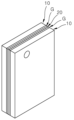
도 6은 본 발명에 의한 전기화학적 수소 압축기를 이용한 연료제어 장치에 채용된 전기 화학적 수소 압축기의 일실시예를 설명하기 위한 사시도.
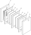
도 7은 본 발명에 채용된 전기 화학적 수소 압축기의 일실시예의 분리 사시도.
도 8은 본 발명에 채용된 전기 화학적 수소 압축기의 일실시예의 부분단면 정면도.
도 9는 도 8의 Ⅸ 부분 확대도.
도 10은 도 9의 Ⅹ부분 발췌단면도.
도 11은 본 발명에 채용된 전기 화학적 수소 압축기의 다른 실시예의 역류방지 패턴막의 구조를 보인 도면.1 is a diagram illustrating a fuel control device using an electrochemical hydrogen compressor according to an embodiment of the present invention.
Figure 2 is a diagram for explaining the operating state of a fuel injection unit employed in one embodiment of the present invention.
Figures 3 and 4 are views for explaining a liquid fuel tank employed in one embodiment of the present invention.
Figure 5 is a diagram for explaining a fuel control device using an electrochemical hydrogen compressor according to another embodiment of the present invention.
Figure 6 is a perspective view illustrating an embodiment of an electrochemical hydrogen compressor employed in a fuel control device using an electrochemical hydrogen compressor according to the present invention.
Figure 7 is an exploded perspective view of one embodiment of an electrochemical hydrogen compressor employed in the present invention.
Figure 8 is a partial cross-sectional front view of one embodiment of the electrochemical hydrogen compressor employed in the present invention.
Figure 9 is an enlarged view of part Ⅸ of Figure 8.
Figure 10 is a cross-sectional view of part X of Figure 9.
Figure 11 is a diagram showing the structure of a backflow prevention pattern film of another embodiment of the electrochemical hydrogen compressor employed in the present invention.
이하에서는 본 발명의 일실시예에 의한 전기화학적 수소 압축기를 이용한 연료제어 장치를 첨부된 도면을 참조하여 상세히 설명하기로 한다. Hereinafter, a fuel control device using an electrochemical hydrogen compressor according to an embodiment of the present invention will be described in detail with reference to the attached drawings.
도 1은 본 발명의 일실시예에 의한 전기화학적 수소 압축기를 이용한 연료제어 장치를 설명하기 위한 도면이고, 도 2는 본 발명 일실시예에 채용된 연료 분사 유닛의 작동 상태를 설명하기 위한 도면이며, 도 3 및 도 4는 본 발명 일실시예에 채용된 액체 연료탱크를 설명하기 위한 도면이다. FIG. 1 is a diagram for explaining a fuel control device using an electrochemical hydrogen compressor according to an embodiment of the present invention, and FIG. 2 is a diagram for explaining the operating state of a fuel injection unit employed in an embodiment of the present invention. , FIGS. 3 and 4 are views for explaining the liquid fuel tank employed in one embodiment of the present invention.
이들 도면에 도시된 바와 같이, 본 발명의 일실시예에 의한 전기화학적 수소 압축기를 이용한 연료제어 장치는 전기화학적 수소 압축기(100) 및 연료 분사 유닛(200)을 포함하여 이루어진다. As shown in these figures, a fuel control device using an electrochemical hydrogen compressor according to an embodiment of the present invention includes an
상기 수소 압축기(100)는 액체 연료(이하, '연료'라 함)의 압력과 유량 제어를 위해 이용되는 수소의 이동 경로 상에 배치되어, 전압 인가에 따른 산화 환원 반응에 의해 상기 수로를 압축된 상태로 이동시킬 수 있게 한다. 상기 수소 압축기(100)는 막전극 접합체(20)를 포함하여 이루어짐으로써, 산화 환원 반응을 통해 상기 수소를 압축된 상태로 이동시킨다. 상기 수소 압축기(100)는 외부의 수소 탱크(110)에서 상기 연료 분사 유닛(200)측으로 이동하는 수소의 이동 경로 상에 배치되는 것이 바람직하다. The
상기 연료 분사 유닛(200)은 연료를 저장하고 그 연료의 압력과 유량을 제어하기 위한 것으로 연료 탱크(210) 및 가압디스크(220)를 포함하여 이루어진다. 상기 연료 분사 유닛(200)의 연료 탱크(210)는 내부에 연료의 저장을 위한 공간을 구비하고, 그 공간에 연료를 저장시킨다. 상기 연료 탱크(210)의 내부의 공간에 가압디스크(220)가 마련되며, 그 가압디스크(220)에 의해 가압된 연료를 토출되게 한다. The
상기 연료 분사 유닛(200)의 가압디스크(220)는 연료 탱크(210)의 내부 공간에 이동 가능하게 설치되고, 그 연료 탱크(210) 내부의 공간을 연료저장공간(211)과 수소유입공간(212)으로 분할시킨다. 여기서 상기 연료저장공간(211)에는 연료가 저장되고, 상기 수소유입공간(212)에는 수소 압축기(100)의 토출구와 연결되어 수소를 유입시킨다. 상기 가압디스크(220)는, 수소유입공간(212)으로 유입된 수소 압력에 의해 상기 연료저장공간(211) 측으로 이동되어 그 연료저장공간(211)에 수용되어 있는 연료를 가압하여 토출되게 한다(도 2 및 도 4 참조). The pressurizing
상기 가압디스크(220)는 연료 탱크(210) 내부의 단면 형태와 대응되는 형태로 이루어지며, 그 연료 탱크 내부에서 연료저장공간(211) 측으로 이동된다. 상기 가압디스크(220)는, 수소유입공간(212)으로 유입된 수소가 연료저장공간(211)으로 유입되는 것을 방지하기 위해 그 연료 탱크의 내면과 접촉되는 접촉부분에 실링수단(221)을 구비할 수 있을 것이다. The pressurizing
상기 연료 분사 유닛(200)의 연료 탱크(210) 및 가압디스크(220)는 내부식성과 내마모성을 가진 소재로 이루어질 수 있으며, 우주 발사체의 내부에 설치될 수 있고 그 우주 발사체의 추진체에 연료를 공급시킴으로써, 상기 우주 발사체가 강한 추진력을 확보할 수 있게 한다. The
이러한 구성을 가진 본 발명의 일실시예에 의한 전기화학적 수소 압축기를 이용한 연료제어 장치는, 상기 전기화학적 수소 압축기(100)가 수소를 압축된 상태로 이동될 수 있게 하고, 연료 분사 유닛(200)의 연료 탱크(210)에 배치된 가압디스크(220)에 의해 그 연료 탱크(210)의 내부가 연료저장공간(211) 및 수소유입공간(212)으로 분할되고, 상기 수소유입공간(212)으로 유입된 수소의 압력에 의해 가압디스크(220)가 연료저장공간(211) 측으로 이동되어 연료를 가압하여 토출시킬 수 있게 함으로써, 우주 발사체에 사용되는 연료의 압력과 유량을 정밀하게 제어할 수 있고, 연료 탱크(210)를 원하는 압력으로 유지시키며 연료의 공급 시 맥동 유동을 방지하면서, 고체 연료에 비해 장거리 추진을 가능하게 하며 강한 추진력을 얻을 수 있게 하는 효과를 가진다. The fuel control device using an electrochemical hydrogen compressor according to an embodiment of the present invention having this configuration allows the
한편 상기 연료 분사 유닛(200)은 연결로드(230)를 더 포함하여 이루어지는 것이 바람직하다. 상기 연료 분사 유닛(200)의 연결로드(230)는 길게 형성된 바 형태로 이루어질 수 있고, 일측이 상기 연료 탱크(210)의 중심부를 관통하여 가압디스크(220)에 연결되며, 타측이 연료 탱크(210)의 외부로 노출된다. 상기 연결로드(230)는 가압디스크(220)에 연결된 상태에서, 가압디스크(220)의 이동 시에 연료 탱크를 관통한 상태에서 그 가압디스크와 함께 이동됨으로써, 수소 압력에 의해 가압디스크(220)가 이동될 때 그 가압디스크(220)의 틀어짐을 방지하면서 균일한 이동(연료저장공간 측으로 하강)을 가이드한다. Meanwhile, the
상기 연결로드(230)는 가압디스크(220)와 접합 방식이나 나사결합 방식 등으로 결합될 수 있고, 상기 가압디스크(220)와 동일한 소재로 이루어져서 일체형으로도 이루어질 수 있을 것이다. 또한 상기 연료 분사 유닛(200)은 가압된 연료의 토출을 위해 연료 토출구 측에 토출밸브(V1)를 구비할 수 있고, 제어기(미도시)에 의한 제어를 통해 그 토출밸브(V1)의 구동이 이루어질 수 있을 것이다. The connecting
한편 상기 연료 분사 유닛(200)은, 외부의 액체 연료탱크(T)와 연결되어서 연료 탱크(210)의 상기 연료저장공간(211)으로 연료가 주입되도록 할 수 있고, 상기 액체 연료탱크(T)와 연결되는 부분에 연료주입밸브(V2)를 구비하여서 주입된 연료의 역류를 방지하고 연료의 주입을 제어할 수 있을 것이다(도 3 및 도 4 참조). 또한 상기 연료 분사 유닛(200)은 연료 탱크(210)와 전기화학적 수소 압축기(100) 사이에 수소토출밸브(V3)를 구비할 수 있다. 본 실시예에서 채용되는 밸브들은 제어기의 제어를 통해 구동될 수 있고, 연료저장공간(211)의 압력에 따라 수소의 주입량이 조절되게 하여 상기 연료저장공간(211)의 압력을 균일하게 유지할 수 있도록 한다.Meanwhile, the
또한 상기 연료 분사 유닛(200)은 연료저장공간(211)과 수소유입공간(212)의 압력을 측정하기 위해 압력센서(P)를 구비할 수 있다. 상기 압력센서(P)는 상기 연료 탱크(210) 내부의 압력을 측정할 수 있게 하고, 제어부가 그 측정값에 기초하여 수소토출밸브(V3)와 토출밸브(V1)의 구동을 제어할 수 있게 한다. Additionally, the
이상 본 발명의 일실시예에 의한 전기화학적 수소 압축기를 이용한 연료제어 장치를 설명하였다. 이하에서는 본 발명의 다른 실시예에 의한 전기화학적 수소 압축기를 이용한 연료제어 장치를 설명하기로 한다. The fuel control device using an electrochemical hydrogen compressor according to an embodiment of the present invention has been described above. Hereinafter, a fuel control device using an electrochemical hydrogen compressor according to another embodiment of the present invention will be described.
도 5는 본 발명의 다른 실시예에 의한 전기화학적 수소 압축기를 이용한 연료제어 장치를 설명하기 위한 도면이다. Figure 5 is a diagram for explaining a fuel control device using an electrochemical hydrogen compressor according to another embodiment of the present invention.
본 실시예는 앞서 설명한 실시예와 대부분의 구성이 유사하나 연료 분사 유닛(200)의 구조에 있어서 차이점이 있다. This embodiment is similar in most configurations to the previously described embodiment, but there is a difference in the structure of the
즉 본 실시예에 채용된 연료 분사 유닛(200)은, 연료 탱크(210)와 수소 유입 탱크(400)가 별도로 마련되어서 연료와 수소가 개별적으로 저장되게 한다. 상기 수소 유입 탱크(400)는 연료 탱크(210)와 인접하게 마련되고, 전기화학적 수소 압축기(100)의 토출구와 연결되어서 수소가 내부로 유입될 수 있게 한다. 또한 상기 연료 탱크(210)는 연료 탱크 내부에 이동 가능하게 설치되는 연료측 디스크(213)를 포함하여 이루어짐으로써, 그 연료 탱크 내부의 공간이 2분할된다. 상기 연료 탱크에서 분할된 공간 중 연료가 토출되는 부분(연료 탱크에서 하부)에 상기 연료가 저장된다. That is, the
또한 상기 연료 분사 유닛(200)의 수소 유입 탱크(400)의 내부에는 수소측 디스크(410)가 마련된다. 상기 수소측 디스크(410)는 수소 유입 탱크(400) 내에서 이동 가능하게 설치되고, 상기 수소 유입 탱크 내의 공간을 2분할시킨다. 상기 수소 유입 탱크(400)의 2분할된 공간 중 상기 전기화학적 수소 압축기(100)의 토출구와 연결된 부분(수소 유입 탱크의 상부)에는 상기 수소가 수용된다. Additionally, a
아울러 상기 연료 분사 유닛(200)은, 연료측 디스크(213)와 수소측 디스크(410)를 연결시키는 연결로드(230)를 더 포함하여 이루어지는 것이 바람직하다. 본 실시예에 채용된 상기 연결로드(230)는, 일측이 연료 탱크(210)를 관통하여 상기 연료측 디스크(213)에 연결되고, 타측이 상기 수소 유입 탱크(400)를 관통하여 상기 수소측 디스크(410)에 연결됨으로써, 상기 수소 유입 탱크로 유입된 수소에 의한 압력으로 상기 수소측 디스크(410)가 연료 탱크(210)를 향해 이동될 때 상기 연료측 디스크(213)를 함께 이동시켜서 연료를 압축시킬 수 있게 한다(도 5의 (b) 참조). In addition, the
한편, 상기 연료 탱크(210)는 상부가 수요 유입 탱크(400)의 하부와 접하도록 배치될 수 있고, 상기 수소 유입 탱크(400)와 분리된 상태로 배치될 수 있을 것이다. 또한 상기 연료측 디스크(213), 수소측 디스크(410) 및 연결로드(230)는 일체형 또는 분리형으로 이루어질 수도 있다. Meanwhile, the upper part of the
또한 본 실시예는, 상기 수소 유입 탱크(400) 내부로 유입된 수소 압력에 의해 상기 수소측 디스크(410)가 가압되어서 연료측 디스크(213)와 함께 이동되고, 상기 연료 탱크(210)에 수용되어 있는 연료를 가압하여 토출되게 하며, 연료가 유입되는 공간과 수소가 유입되는 공간을 연료 탱크(210)와 수소 유입 탱크(400)로 각각 별도로 형성함으로써, 상기 연료와 수소가 서로 섞이지 않게 하고 그 연료와 수소 간의 반응을 방지할 수 있게 한다. In addition, in this embodiment, the
이상 본 발명에 의한 전기화학적 수소 압축기를 이용한 연료제어 장치를 설명하였다. 이하에서는 본 발명에 채용된 전기화학적 수소 압축기의 일실시예에 대하여 설명하기로 한다. The fuel control device using the electrochemical hydrogen compressor according to the present invention has been described above. Hereinafter, an embodiment of the electrochemical hydrogen compressor employed in the present invention will be described.
도 6은 본 발명에 의한 전기화학적 수소 압축기를 이용한 연료제어 장치에 채용된 전기 화학적 수소 압축기의 일실시예를 설명하기 위한 사시도이고, 도 7은 본 발명에 채용된 전기 화학적 수소 압축기의 일실시예의 분리 사시도이며, 도 8은 본 발명에 채용된 전기 화학적 수소 압축기의 일실시예의 부분단면 정면도이며, 도 9는 도 8의 Ⅸ 부분 확대도이며, 도 10은 도 9의 Ⅹ부분 발췌단면도이다. Figure 6 is a perspective view for explaining an embodiment of the electrochemical hydrogen compressor employed in the fuel control device using the electrochemical hydrogen compressor according to the present invention, and Figure 7 is an embodiment of the electrochemical hydrogen compressor employed in the present invention. It is an separated perspective view, Figure 8 is a partial cross-sectional front view of an embodiment of the electrochemical hydrogen compressor employed in the present invention, Figure 9 is an enlarged view of part Ⅸ of Figure 8, and Figure 10 is a cross-sectional view of part Ⅹ of Figure 9.
이들 도면에 도시된 바와 같이, 본 발명의 각 실시예에 채용된 전기화학적 수소 압축기(100)는 한 쌍의 분리판들(10), 막전극 접합체(20) 및 역류방지 패턴막(30)을 포함하여 이루어진다. As shown in these figures, the
상기 한 쌍의 분리판들(10)은 각각 수소가 이동할 수 있는 수소이동로가 형성되어 있고, 인접한 플레이트 또는 필름 형태의 요소들과 적층이 가능하도록 두께가 얇은 판 형태로 형성되며, 동일한 축선상에 간격을 두고 서로 대향 배치된다. 이러한 각 분리판(10)은 구리나 알루미늄과 같은 통전이 가능한 재질로 형성되고 전류가 인가되는 집전판(도시되지 않음)과 전기적으로 연결되어서 그 인가된 전류를 상기 막전극 접합체(20)에 전달시켜 줄 수 있게 한다(도 7 참조).The pair of
상기 막전극 접합체(20)는 상기 한 쌍의 분리판들(10) 중 어느 하나를 통과한 수소의 이동 경로 상에 배치되어, 전압 인가에 따른 산화 환원 반응에 의해 수소를 압축된 상태로 다른 하나의 분리판 측으로 이동시킬 수 있게 한다. 상기 막전극 접합체(20)는, 수소 이온을 이동시켜주는 고분자 전해질막, 전해질막의 양면에 백금 촉매를 도포하여 구성되는 촉매전극인 양극(Anode, 공기극)과 음극(Cathode, 연료극)으로 이루어져서, 양극에서의 산화 반응에 의해 수소를 이온화시키고 이온화된 수소 이온을 고분자 전해질막을 통해 이동시킨 후 음극에서 환원 반응에 의해 수소를 압축시킬 수 있게 한다(도 및 도 7 참조).The
상기 역류방지 패턴막(30)은 상기 다른 하나의 분리판(10)과 막전극 접합체(20) 사이에 배치되는 것으로, 복수의 통과슬릿(31)들과 역류방지부(32)들을 포함하여 이루어지고, 전도성 고무, 기능성 재료(Carbon black, Graphene nanoplatelets, ZnO nanorods, AgNWs, Graphene Oxide 등) 기반 실리콘이나 아크릴 계열 고분자(PDMS, polydimethylsiloxane) 또는 이들의 조합으로 구성될 수 있다(도 8 내지 도 10 참조).The backflow
상기 역류방지 패턴막(30)의 통과슬릿(31)은 상기 막전극 접합체(20)를 통과한 수소가 상기 다른 하나의 분리판(10) 측으로 유입될 수 있게 하는 수소의 순방향(도 9의 실선 화살표 방향) 이동 통로 역할을 하고, 상기 각 역류방지부(32)는 상기 각 통과슬릿(31)을 통과한 수소가 반대방향인 역방향(도 9의 점선 화살표 방향)으로 역류하는 것을 방지시켜 주기 역할을 한다.The passage slit 31 of the backflow
이러한 구성을 가지는 본 발명에 의한 전기화학적 수소 압축기는 산화-환원 반응에 의한 수소 압축이 발생하는 막전극 접합체(20)와 분리판(10) 사이에 배치된 역류방지 패턴막(30)을 포함하여 이루어져서, 그 막전극 접합체(20)과 역류방지 패턴막(30)을 통과함으로써 압축된 수소가 막전극 접합체(20) 측으로 역확산되는 것을 억제시킬 수 있게 됨에 따라, 수소 압축 효율을 향상시킬 수 있는 장점을 가진다.The electrochemical hydrogen compressor according to the present invention having this configuration includes a backflow
한편, 상기 역류방지 패턴막(30)은 상기 압축된 수소의 역확산 방지를 위한 다양한 구조 또는 재질에 의해 구현될 수 있음은 물론이나, 본 실시예에서는 탄성을 가진 전도성 폴리머 재질을 포함하여 이루어져서, 그 역류방지 패턴막(30)의 기본 구성인 상기 통과슬릿(31)과 역류방지부(32)를 하나의 재질에 의해 일체로 형성시킬 수 있도록 구성됨에 따라 성형의 용이성 및 구조의 간소화를 이룰 수 있게 하여 제품의 양산성 향상 및 제조원가 절감을 가능하게 한다.Meanwhile, the backflow
또한 상기 역류방지부(32)는 수소의 순방향 통과시 서로 틈새를 형성하도록 이격되어서 수소 통과를 가능하게 하고, 수소 통과 이후 상기 틈새를 메우는 원래의 위치로 복원되어서 수소의 역방향 역류를 방지시키는 탄성을 가진 한 쌍의 밸브체(32a)(32b)들을 포함하여 이루어진다(도 10 참조).In addition, the
이러한 구성을 가지는 본 실시예는 유체의 역방향 흐름을 방지시키는 일반적인 체크 밸브 또는 혈액의 역방향 흐름을 방지시키는 인공 판막과 같은 구조를 가진 한 쌍의 밸브체(32a)(32b)를 수소 압축기의 역류방지 패턴막(30)의 주요 구성으로 하고, 이러한 역류방지 패턴막(30)을 수소 압축기의 막전극 접합체(20) 및 분리판(10)과 유기적으로 결합시킴으로써 수소 압축 효율을 향상시킬 수 있게 하는 장점을 도출한다.This embodiment, which has this configuration, uses a pair of
한편 본 실시예 채용된 상기 역류방지 패턴막(30)은 상기 막전극 접합체(20)를 거쳐 수소가 압축된 이후 그 압축된 수소의 역확산을 방지시킬 수 있도록 상기 다른 하나의 분리판(10)과 막전극 접합체(20) 사이에 배치되는 것에 더하여, 그 막전극 접합체(20) 통과 이전의 수소가 상기 다른 하나의 분리판(10)과 대향 배치되는 어느 하나의 분리판(10) 측으로 역확산되는 것을 억제시킬 수 있도록, 그 어느 하나의 분리판(10)과 막전극 접합체(20) 사이에도 배치되도록 구성되었다.Meanwhile, the backflow
또한 본 실시예는 상기 역류방지 패턴막(30)과 막전극 접합체(20) 사이에 배치되는 가스 디퓨저 레이어(40)를 더 포함하여 이루어질 수 있다. Additionally, this embodiment may further include a
상기 가스 디퓨저 레이어(40)는 다공질 전도성 소재인 카본페이퍼 또는 메탈폼 재질로 이루어져서, 상기 분리판(10)에서 유동하는 가스의 막전극 접합체(20)로 향한 이동을 방해하지 않고, 상기 막전극 접합체(20)에 인가된 전압에 의한 산화반응이 수소가 이동하는 경로 전체에 걸쳐 골고루 일어나도록 하여, 수소압축 효율 향상에 기여하게 된다.The
그리고, 상기 분리판(10)과 막전극 접합체(20) 사이에는 실링을 위해 가스켓(G)이 설치되는데, 상기 가스 디퓨저 레이어(40)는 이러한 가스켓(G)과 간섭되지 않는 위치에 배치되는 것이 바람직하다.In addition, a gasket (G) is installed between the
이상 본 발명에 채용된 전기화학적 수소 압축기의 일실시예에 대하여 설명하였다. 이하에서는 본 발명에 채용된 전기화학적 수소 압축기의 다른 실시예에 대하여 설명하기로 한다. Above, an embodiment of the electrochemical hydrogen compressor employed in the present invention has been described. Hereinafter, another embodiment of the electrochemical hydrogen compressor employed in the present invention will be described.
도 11은 본 발명에 채용된 전기 화학적 수소 압축기의 다른 실시예의 역류방지 패턴막의 구조를 보인 도면이다. Figure 11 is a diagram showing the structure of a backflow prevention pattern film of another embodiment of the electrochemical hydrogen compressor employed in the present invention.
본 실시예에 채용된 역류방지 패턴막(300)은, 위에서 설명한 체크밸브와 같은 구조를 가지는 역류방지부(312)들이 하나의 재질에 의해 일체로 형성되는 패턴부(310)와 상기 패턴부(310)를 감싸는 형태로 그 패턴부(310)에 결합되고 상기 막전극 접합체(20)의 전극 부분과 통전이 가능한 전도성 재질로 이루어지는 통전부(320)를 포함하여 이루어져서, 상기 통전부(320)를 통해 막전극 접합체(20) 및 분리판(10)과 전기적으로 연결되고 상기 패턴부(310)를 통해 압축된 수소의 역확산을 방지할 수 있도록 구성되었다.The backflow
이상, 본 발명에 대한 바람직한 실시예를 설명하였으나 본 발명은, 위에서 설명된 실시예들에 한정되지 않고 청구범위에 기재된 바에 의해 정의되며 본 발명이 속하는 기술분야에서 다양한 변형과 개발을 할 수 있음은 자명하다.Although the preferred embodiments of the present invention have been described above, the present invention is not limited to the embodiments described above, but is defined by the claims, and various modifications and developments can be made in the technical field to which the present invention pertains. Self-explanatory.
100: 전기화학적 수소 압축기
110: 수소 탱크
10: 분리판들
20: 막전극 접합체
30, 300: 역류방지 패턴막
31: 통과슬릿
32, 312: 역류방지부
40: 가스 디퓨저 레이어
310: 패턴부
320: 통전부
200: 연료 분사 유닛
P: 압력센서
T: 액체 연료탱크
V1: 토출밸브
V2: 연료주입밸브
V3: 수소토출밸브
210: 연료 탱크
211: 연료저장공간
212: 수소유입공간
213: 연료측 디스크
220: 가압디스크
230: 연결로드
400: 수소 유입 탱크
410: 수소측 디스크100: electrochemical hydrogen compressor 110: hydrogen tank
10: Separation plates 20: Membrane electrode assembly
30, 300: Backflow prevention pattern film 31: Pass slit
32, 312: backflow prevention unit 40: gas diffuser layer
310: Pattern part 320: Electricity part
200: Fuel injection unit P: Pressure sensor
T: Liquid fuel tank V1: Discharge valve
V2: Fuel injection valve V3: Hydrogen discharge valve
210: fuel tank 211: fuel storage space
212: Hydrogen inflow space 213: Fuel side disk
220: Pressurized disk 230: Connecting rod
400: Hydrogen inlet tank 410: Hydrogen side disk
Claims (6)
연료가 저장되는 연료 탱크와, 상기 연료 탱크 내에 이동가능하게 설치되고 그 연료 탱크 내의 공간을 연료가 저장되는 연료저장공간과 수소가 유입되는 수소유입공간(전기화학적 수소 압축기의 토출구와 연결)으로 분할되게 배치되는 것으로, 상기 수소유입공간으로 유입된 수소 압력에 의해 연료저장공간 측으로 이동되어 그 연료저장공간에 수용되어 있는 연료를 가압하여 토출시킬 수 있게 하는 가압디스크를 구비하는 연료 분사 유닛;을 포함하여 이루어지는 것을 특징으로 하는 전기화학적 수소 압축기를 이용한 연료제어 장치.
An electrochemical hydrogen compressor including a membrane electrode assembly disposed on the hydrogen movement path and enabling hydrogen to be moved in a compressed state by an oxidation-reduction reaction according to voltage application; and
A fuel tank in which fuel is stored, movably installed within the fuel tank, and the space within the fuel tank is divided into a fuel storage space in which fuel is stored and a hydrogen inflow space (connected to the discharge port of the electrochemical hydrogen compressor) into which hydrogen flows. It is arranged so that it is moved toward the fuel storage space by the pressure of hydrogen flowing into the hydrogen inflow space, and includes a fuel injection unit having a pressurizing disk that pressurizes and discharges the fuel contained in the fuel storage space. A fuel control device using an electrochemical hydrogen compressor, characterized in that:
상기 연료 분사 유닛은,
일측은 상기 연료 탱크의 중심부를 관통하여 상기 가압디스크에 연결되고, 타측은 연료 탱크의 외부로 노출되는 연결로드;를 포함하여 이루어지는 것을 특징으로 하는 전기화학적 수소 압축기를 이용한 연료제어 장치.
According to paragraph 1,
The fuel injection unit,
A fuel control device using an electrochemical hydrogen compressor, comprising a connecting rod, one side of which penetrates the center of the fuel tank and is connected to the pressurizing disk, and the other side of which is exposed to the outside of the fuel tank.
연료가 저장되는 연료 탱크와, 전기화학적 수소 압축기의 토출구와 연결되어서 수소가 유입되는 수소 유입 탱크와, 상기 연료 탱크 내에 이동 가능하게 설치되고 그 연료 탱크 내의 공간이 2분할되도록 배치되는 연료측 디스크와, 상기 수소 유입 탱크 내에 이동 가능하게 설치되고 그 수소 유입 탱크 내의 공간이 2분할되도록 배치되는 수소측 디스크와, 일측은 상기 연료 탱크를 관통하여 연료측 디스크에 연결되고 타측은 상기 수소 유입 탱크를 관통하여 상기 수소측 디스크에 연결되어서 연료측 디스크와 수소측 디스크를 함께 이동될 수 있게 하는 연결로드를 구비하는 연료 분사 유닛;을 포함하여 이루어져서,
상기 수소 유입 탱크 내부로 유입된 수소 압력에 의해 상기 수소측 디스크가 가압되어서 연료측 디스크와 함께 이동되어서 상기 연료 탱크에 수용되어 있는 연료를 가압하여 토출되게 하고, 연료가 유입되는 공간과 수소가 유입되는 공간을 연료 탱크와 수소 유입 탱크로 각각 별도로 형성하는 것에 의해 서로 섞이지 않게 함으로써 수소와 연료 간의 반응을 방지할 수 있게 하는 것을 특징으로 하는 전기화학적 수소 압축기를 이용한 연료제어 장치.
An electrochemical hydrogen compressor including a membrane electrode assembly disposed on the hydrogen movement path and enabling hydrogen to be moved in a compressed state by an oxidation-reduction reaction according to voltage application; and
A fuel tank in which fuel is stored, a hydrogen inflow tank connected to the discharge port of the electrochemical hydrogen compressor into which hydrogen flows, a fuel side disk movably installed in the fuel tank and arranged to divide the space in the fuel tank into two; , a hydrogen side disk that is movably installed in the hydrogen inlet tank and arranged so that the space in the hydrogen inlet tank is divided into two, one side penetrates the fuel tank and is connected to the fuel side disk, and the other side penetrates the hydrogen inlet tank. and a fuel injection unit including a connecting rod that is connected to the hydrogen side disk and allows the fuel side disk and the hydrogen side disk to move together,
The hydrogen side disk is pressurized by the pressure of the hydrogen flowing into the hydrogen inflow tank and moves together with the fuel side disk to pressurize and discharge the fuel contained in the fuel tank, and the space where the fuel flows and the hydrogen flows. A fuel control device using an electrochemical hydrogen compressor, characterized in that the reaction between hydrogen and fuel is prevented by forming separate spaces into a fuel tank and a hydrogen inlet tank so that they do not mix.
상기 전기화학적 수소 압축기는,
각각 수소가 이동할 수 있는 수소이동로가 형성되어 있고, 동일한 축선 상에
간격을 두고 서로 대향 배치되는 한 쌍의 분리판들;
상기 한 쌍의 분리판들 중 어느 하나를 통과한 수소의 이동 경로 상에 배치
되어, 전압 인가에 따른 산화 환원 반응에 의해 수소를 압축된 상태로 다른 하나의
분리판 측으로 이동시킬 수 있게 하는 막전극 접합체; 및
상기 다른 하나의 분리판과 막전극 접합체 사이에 배치되는 것으로, 상기 막
전극 접합체를 통과한 수소가 상기 다른 하나의 분리판 측으로 유입될 수 있게 하는 복수의 통과슬릿들과, 상기 각 통과슬릿을 통과한 수소가 역류하는 것을 방지시켜 주기 위한 역류방지부들이 마련되어 있는 역류방지 패턴막;을 포함하여 이루어지는 것을 특징으로 하는 전기화학적 수소 압축기를 이용한 연료제어 장치.
According to any one of claims 1 to 3,
The electrochemical hydrogen compressor,
Each hydrogen passageway is formed through which hydrogen can move, and on the same axis
A pair of separation plates arranged opposite each other at intervals;
Placed on the path of hydrogen passing through one of the pair of separator plates
Hydrogen is compressed by an oxidation-reduction reaction upon voltage application and is converted into another
A membrane electrode assembly that allows movement to the separator side; and
disposed between the other separator plate and the membrane electrode assembly, wherein the membrane
A backflow prevention device is provided with a plurality of passage slits that allow hydrogen that has passed through the electrode assembly to flow into the other separator side, and backflow prevention units that prevent the hydrogen that has passed through each passage slit from flowing back. A fuel control device using an electrochemical hydrogen compressor, comprising a patterned film.
상기 역류방지 패턴막은 탄성을 가진 전도성 폴리머 재질을 포함하여 이루어지는 것을 특징으로 하는 전기화학적 수소 압축기를 이용한 연료제어 장치.
According to paragraph 4,
A fuel control device using an electrochemical hydrogen compressor, wherein the backflow prevention pattern film includes an elastic conductive polymer material.
상기 각 역류방지부는, 수소의 순방향 통과시 서로 틈새를 형성하도록 이격되어서 수소 통과를 가능하게 하고, 수소 통과 이후 상기 틈새를 메우는 원래의 위치로 복원되어서 수소의 역방향 역류를 방지시키는 탄성을 가진 한 쌍의 밸브체들을 포함하는 것을 특징으로 하는 전기화학적 수소 압축기를 이용한 연료제어 장치.According to paragraph 4,
Each of the backflow prevention units is spaced apart from each other to form a gap when hydrogen passes in the forward direction, allowing hydrogen to pass through, and is restored to its original position to fill the gap after the hydrogen passes through, so it is a pair having elasticity to prevent reverse backflow of hydrogen. A fuel control device using an electrochemical hydrogen compressor, characterized in that it includes valve elements.
Priority Applications (1)
| Application Number | Priority Date | Filing Date | Title |
|---|---|---|---|
| KR1020220039700A KR102724438B1 (en) | 2022-03-30 | 2022-03-30 | Fuel control device using electrochemical compressor |
Applications Claiming Priority (1)
| Application Number | Priority Date | Filing Date | Title |
|---|---|---|---|
| KR1020220039700A KR102724438B1 (en) | 2022-03-30 | 2022-03-30 | Fuel control device using electrochemical compressor |
Publications (2)
| Publication Number | Publication Date |
|---|---|
| KR20230140887A true KR20230140887A (en) | 2023-10-10 |
| KR102724438B1 KR102724438B1 (en) | 2024-10-30 |
Family
ID=88292476
Family Applications (1)
| Application Number | Title | Priority Date | Filing Date |
|---|---|---|---|
| KR1020220039700A Active KR102724438B1 (en) | 2022-03-30 | 2022-03-30 | Fuel control device using electrochemical compressor |
Country Status (1)
| Country | Link |
|---|---|
| KR (1) | KR102724438B1 (en) |
Cited By (1)
| Publication number | Priority date | Publication date | Assignee | Title |
|---|---|---|---|---|
| WO2026102224A1 (en) * | 2024-11-07 | 2026-05-15 | Stoke Space Technologies, Inc. | Hydrogen pressurization of a tank with a liquid stored therein |
Citations (6)
| Publication number | Priority date | Publication date | Assignee | Title |
|---|---|---|---|---|
| JP2003148688A (en) * | 2001-11-13 | 2003-05-21 | Hitachi Constr Mach Co Ltd | Compressed natural gas supply device, compressed natural gas supply system, and compressed natural gas supply method |
| KR20140003768A (en) * | 2012-06-28 | 2014-01-10 | 현대제철 주식회사 | Device for storage of gas |
| CN203594973U (en) * | 2013-12-05 | 2014-05-14 | 重庆梅安森科技股份有限公司 | Gas output device capable of keeping gas flow stable |
| CN106382462A (en) * | 2016-11-18 | 2017-02-08 | 贵州望江气体有限公司 | High pressure gas filling process |
| KR20200086530A (en) * | 2019-01-09 | 2020-07-17 | 현대자동차주식회사 | Electrochemical hydrogen compressor |
| CN214580428U (en) * | 2021-04-02 | 2021-11-02 | 蒲城清洁能源化工有限责任公司 | A liquid ammonia delivery system |
-
2022
- 2022-03-30 KR KR1020220039700A patent/KR102724438B1/en active Active
Patent Citations (6)
| Publication number | Priority date | Publication date | Assignee | Title |
|---|---|---|---|---|
| JP2003148688A (en) * | 2001-11-13 | 2003-05-21 | Hitachi Constr Mach Co Ltd | Compressed natural gas supply device, compressed natural gas supply system, and compressed natural gas supply method |
| KR20140003768A (en) * | 2012-06-28 | 2014-01-10 | 현대제철 주식회사 | Device for storage of gas |
| CN203594973U (en) * | 2013-12-05 | 2014-05-14 | 重庆梅安森科技股份有限公司 | Gas output device capable of keeping gas flow stable |
| CN106382462A (en) * | 2016-11-18 | 2017-02-08 | 贵州望江气体有限公司 | High pressure gas filling process |
| KR20200086530A (en) * | 2019-01-09 | 2020-07-17 | 현대자동차주식회사 | Electrochemical hydrogen compressor |
| CN214580428U (en) * | 2021-04-02 | 2021-11-02 | 蒲城清洁能源化工有限责任公司 | A liquid ammonia delivery system |
Cited By (1)
| Publication number | Priority date | Publication date | Assignee | Title |
|---|---|---|---|---|
| WO2026102224A1 (en) * | 2024-11-07 | 2026-05-15 | Stoke Space Technologies, Inc. | Hydrogen pressurization of a tank with a liquid stored therein |
Also Published As
| Publication number | Publication date |
|---|---|
| KR102724438B1 (en) | 2024-10-30 |
Similar Documents
| Publication | Publication Date | Title |
|---|---|---|
| US10301179B2 (en) | Electrochemical hydrogen pump | |
| JP7249588B2 (en) | electrochemical hydrogen pump | |
| US11228044B2 (en) | Bipolar plate having asymmetrical sealing sections, and fuel cell stack having such a bipolar plate | |
| US11239477B2 (en) | Purge circuit of a fuel cell | |
| CN103081195B (en) | electrochemically actuated valve | |
| US7674550B2 (en) | Fuel cell | |
| KR101632092B1 (en) | Preventing migration of liquid electrolyte out of a fuel cell | |
| US20070246363A1 (en) | Integrated electrochemical hydrogen compression systems | |
| JP2014529851A (en) | Fuel cell system comprising an ejector for recirculating off-gas from the stack | |
| US7807308B2 (en) | Fuel cell system and start-up method | |
| JP2013182818A (en) | Fuel cell stack | |
| KR102258287B1 (en) | Electrochemical hydrogen compressor | |
| WO2007124389A2 (en) | Integrated electrochemical hydrogen separation systems | |
| CN116826110A (en) | Fuel cell activation method and device | |
| JP2004207071A (en) | Fuel cell | |
| KR102724438B1 (en) | Fuel control device using electrochemical compressor | |
| EP3238298A1 (en) | Anode chambers with variable volumes | |
| CN109546177B (en) | Fuel cell sealing device | |
| CN102187505A (en) | Fuel cell and fuel cell system | |
| JP7002045B1 (en) | Compressor and compressor control method | |
| US20060141322A1 (en) | Fuel cell system | |
| Niaz et al. | Tracing resistances of anion exchange membrane water electrolyzer during long-term stability tests | |
| KR102865627B1 (en) | Hydrogen recirculation system for fuel cell stack | |
| US7374836B2 (en) | Fuel cell apparatus | |
| US8968950B2 (en) | Method of starting operation of solid polymer electrolyte fuel cell |
Legal Events
| Date | Code | Title | Description |
|---|---|---|---|
| PA0109 | Patent application |
Patent event code: PA01091R01D Comment text: Patent Application Patent event date: 20220330 |
|
| PA0201 | Request for examination | ||
| PG1501 | Laying open of application | ||
| E902 | Notification of reason for refusal | ||
| PE0902 | Notice of grounds for rejection |
Comment text: Notification of reason for refusal Patent event date: 20240405 Patent event code: PE09021S01D |
|
| E701 | Decision to grant or registration of patent right | ||
| PE0701 | Decision of registration |
Patent event code: PE07011S01D Comment text: Decision to Grant Registration Patent event date: 20240813 |
|
| GRNT | Written decision to grant | ||
| PR0701 | Registration of establishment |
Comment text: Registration of Establishment Patent event date: 20241028 Patent event code: PR07011E01D |
|
| PR1002 | Payment of registration fee |
Payment date: 20241028 End annual number: 3 Start annual number: 1 |
|
| PG1601 | Publication of registration |