KR20230117841A - Corner module apparatus for vehicle - Google Patents
Corner module apparatus for vehicle Download PDFInfo
- Publication number
- KR20230117841A KR20230117841A KR1020220014080A KR20220014080A KR20230117841A KR 20230117841 A KR20230117841 A KR 20230117841A KR 1020220014080 A KR1020220014080 A KR 1020220014080A KR 20220014080 A KR20220014080 A KR 20220014080A KR 20230117841 A KR20230117841 A KR 20230117841A
- Authority
- KR
- South Korea
- Prior art keywords
- unit
- knuckle
- steering
- vehicle
- joint
- Prior art date
- Legal status (The legal status is an assumption and is not a legal conclusion. Google has not performed a legal analysis and makes no representation as to the accuracy of the status listed.)
- Pending
Links
Images


Classifications
-
- B—PERFORMING OPERATIONS; TRANSPORTING
- B62—LAND VEHICLES FOR TRAVELLING OTHERWISE THAN ON RAILS
- B62D—MOTOR VEHICLES; TRAILERS
- B62D5/00—Power-assisted or power-driven steering
- B62D5/04—Power-assisted or power-driven steering electrical, e.g. using an electric servo-motor connected to, or forming part of, the steering gear
- B62D5/0418—Electric motor acting on road wheel carriers
-
- B—PERFORMING OPERATIONS; TRANSPORTING
- B62—LAND VEHICLES FOR TRAVELLING OTHERWISE THAN ON RAILS
- B62D—MOTOR VEHICLES; TRAILERS
- B62D7/00—Steering linkage; Stub axles or their mountings
- B62D7/06—Steering linkage; Stub axles or their mountings for individually-pivoted wheels, e.g. on king-pins
- B62D7/14—Steering linkage; Stub axles or their mountings for individually-pivoted wheels, e.g. on king-pins the pivotal axes being situated in more than one plane transverse to the longitudinal centre line of the vehicle, e.g. all-wheel steering
-
- B—PERFORMING OPERATIONS; TRANSPORTING
- B62—LAND VEHICLES FOR TRAVELLING OTHERWISE THAN ON RAILS
- B62D—MOTOR VEHICLES; TRAILERS
- B62D7/00—Steering linkage; Stub axles or their mountings
- B62D7/16—Arrangement of linkage connections
-
- B—PERFORMING OPERATIONS; TRANSPORTING
- B62—LAND VEHICLES FOR TRAVELLING OTHERWISE THAN ON RAILS
- B62D—MOTOR VEHICLES; TRAILERS
- B62D7/00—Steering linkage; Stub axles or their mountings
- B62D7/18—Steering knuckles; King pins
Landscapes
- Engineering & Computer Science (AREA)
- Chemical & Material Sciences (AREA)
- Combustion & Propulsion (AREA)
- Transportation (AREA)
- Mechanical Engineering (AREA)
- Steering-Linkage Mechanisms And Four-Wheel Steering (AREA)
Abstract
본 발명은 차량용 코너 모듈 장치에 관한 것으로, 차량의 휠의 내측에 설치되고, 휠에 구동력을 제공하는 구동유닛과, 구동유닛과 결합되는 제1너클부와, 제1너클부와 차량의 폭 방향으로 이격되어 마주보게 배치되는 제2너클부와, 제2너클부에 연결되고, 차체에 대해 제2너클부를 지지하는 서스펜션유닛과, 제2너클부에 설치되어 조향력을 생성하는 조향구동부 및 제1너클부와 연결되고, 조향구동부로부터 생성되는 조향력에 연동되어 휠의 조향각을 조절하는 조향각조절부를 포함하는 것을 특징으로 한다.The present invention relates to a corner module device for a vehicle, and relates to a drive unit installed inside a wheel of a vehicle and providing a driving force to the wheel, a first knuckle portion coupled to the drive unit, and the first knuckle portion in the width direction of the vehicle. A second knuckle part spaced apart from each other and disposed facing each other, a suspension unit connected to the second knuckle part and supporting the second knuckle part with respect to the vehicle body, a steering driving unit installed in the second knuckle part to generate a steering force, and a first It is characterized in that it includes a steering angle control unit connected to the knuckle unit and interlocked with the steering force generated from the steering drive unit to adjust the steering angle of the wheel.
Description
본 발명은 차량용 코너 모듈 장치에 관한 것으로, 보다 상세하게는 구동, 제동, 조향, 현가 시스템이 일체형으로 구성되는 차량용 코너 모듈 장치에 관한 것이다.The present invention relates to a corner module device for a vehicle, and more particularly, to a corner module device for a vehicle in which a driving, braking, steering, and suspension system are integrally configured.
일반적으로, 전기자동차는 배기가스의 배출이 전혀 없는 친환경 차량을 말하며, 주행을 위한 에너지를 공급하는 고전압 배터리와, 고전압 배터리로부터 출력되는 전력으로부터 회전력을 발생시키는 주행용 모터 등이 탑재되어 있고, 모터의 회전동력이 구동축을 통해 휠로 전달되어 주행이 이루어진다.In general, an electric vehicle refers to an eco-friendly vehicle that does not emit exhaust gas at all, and is equipped with a high-voltage battery that supplies energy for driving and a driving motor that generates rotational force from power output from the high-voltage battery. The rotational power is transmitted to the wheels through the drive shaft to drive.
최근에는 감속기나 차동기어와 같은 중간 단계의 동력전달장치를 생략할 수 있어 차량의 무게를 감소시킬 수 있고, 동력전달과정에서의 에너지 손실을 저감시킬 수 있는 장점을 고려하여 휠의 내부에 모터를 직접 내설하여 모터의 동력이 휠에 직접 전달하도록 하는 인휠 모터 차량이 각광받고 있으며, 이에 더 나아가 구동 시스템뿐만 아니라 제동, 조향, 현가 시스템이 일체형으로 구성된 휠에 대한 개발 또한 활발하게 이루어지고 있다.Recently, the weight of the vehicle can be reduced by omitting intermediate power transmission devices such as reducers and differential gears, and motors are installed inside the wheels in consideration of the advantages of reducing energy loss in the power transmission process. In-wheel motor vehicles, which are directly installed in the snow and transmit power from the motor directly to the wheels, are in the limelight, and furthermore, development of wheels composed of an integrated braking, steering, and suspension system as well as a driving system is actively being carried out.
본 발명의 배경기술은 대한민국 공개특허공보 제10-2019-0041855호(2019.04.23 공개, 발명의 명칭: 인휠 모터 차량의 조향 시스템)에 개시되어 있다.The background art of the present invention is disclosed in Republic of Korea Patent Publication No. 10-2019-0041855 (published on April 23, 2019, title of the invention: steering system for in-wheel motor vehicles).
본 발명은 각각의 휠의 동작을 독립적으로 제어할 수 있는 차량용 코너 모듈 장치를 제공하는데 그 목적이 있다.An object of the present invention is to provide a corner module device for a vehicle capable of independently controlling the operation of each wheel.
또한, 본 발명은 타이로드 없이도 주행 안정성을 확보할 수 있는 차량용 코너 모듈 장치를 제공하는데 그 목적이 있다.In addition, an object of the present invention is to provide a corner module device for a vehicle capable of securing driving stability without a tie rod.
상술한 과제를 해결하기 위해 본 발명에 따른 차량용 코너 모듈 장치는: 차량의 휠의 내측에 설치되고, 상기 휠에 구동력을 제공하는 구동유닛; 상기 구동유닛과 결합되는 제1너클부; 상기 제1너클부와 상기 차량의 폭 방향으로 이격되어 마주보게 배치되는 제2너클부; 상기 제2너클부에 연결되고, 차체에 대해 상기 제2너클부를 지지하는 서스펜션유닛; 상기 제2너클부에 설치되어 조향력을 생성하는 조향구동부; 및 상기 제1너클부와 연결되고, 상기 조향구동부로부터 생성되는 조향력에 연동되어 상기 휠의 조향각을 조절하는 조향각조절부;를 포함한다.In order to solve the above problems, a corner module device for a vehicle according to the present invention includes: a driving unit installed inside a wheel of a vehicle and providing a driving force to the wheel; a first knuckle portion coupled to the driving unit; a second knuckle part disposed to face the first knuckle part and spaced apart from each other in the width direction of the vehicle; a suspension unit connected to the second knuckle part and supporting the second knuckle part with respect to the vehicle body; a steering drive unit installed in the second knuckle unit to generate a steering force; and a steering angle adjusting unit that is connected to the first knuckle unit and adjusts the steering angle of the wheel by interlocking with the steering force generated from the steering driving unit.
또한, 상기 제2너클부는, 상기 제1너클부와 마주보게 배치되고, 상기 조향구동부가 삽입되는 수용부가 구비되는 바디부; 상기 바디부의 일측으로부터 연장되고, 상기 조향각조절부를 지지하는 마운팅부; 상기 마운팅부로부터 연장되고, 상기 서스펜션유닛에 구비되는 제1암과 연결되는 제1연결부; 및 상기 바디부의 타측으로부터 연장되고, 상기 서스펜션유닛에 구비되는 제2암과 연결되는 제2연결부;를 포함한다.The second knuckle part may include a body part disposed to face the first knuckle part and provided with an accommodating part into which the steering driving part is inserted; a mounting portion extending from one side of the body portion and supporting the steering angle adjusting portion; a first connection portion extending from the mounting portion and connected to a first arm provided in the suspension unit; and a second connection portion extending from the other side of the body portion and connected to a second arm provided in the suspension unit.
상기 제1연결부와 상기 제2연결부는 지면에 대해 수직한 방향으로 나란하게 배치된다.The first connection part and the second connection part are disposed side by side in a direction perpendicular to the ground.
또한, 상기 조향각조절부는, 상기 제2너클부에 결합되고, 상기 조향구동부로부터 생성되는 조향력을 감속하여 출력하는 감속부; 및 상기 감속부로부터 출력되는 조향력을 상기 제1너클부로 전달하여 상기 휠의 조향각을 가변시키는 조인트부;를 포함한다.In addition, the steering angle control unit, coupled to the second knuckle portion, a deceleration unit for outputting the decelerated steering force generated from the steering drive unit; and a joint unit that transmits the steering force output from the deceleration unit to the first knuckle unit to vary the steering angle of the wheel.
또한, 상기 감속부는, 상기 조향구동부의 입력축과 함께 회전되는 제1전달기어부; 상기 제1전달기어부와 맞물려 결합되고, 상기 제1전달기어부의 회전에 연동되어 회전되는 제2전달기어부; 및 상기 제2전달기어부와 맞물려 결합되고, 상기 제2전달기어부의 회전에 연동되어 출력축을 회전시키는 제3전달기어부;를 포함한다.In addition, the reduction unit may include a first transmission gear unit rotated together with the input shaft of the steering drive unit; a second transmission gear unit engaged with the first transmission gear unit and rotated in conjunction with the rotation of the first transmission gear unit; and a third transmission gear unit engaged with the second transmission gear unit and rotating the output shaft in conjunction with rotation of the second transmission gear unit.
또한, 상기 제1전달기어부는 외주면에 웜나사산이 구비된 웜축의 형태를 갖도록 형성된다.In addition, the first transmission gear unit is formed to have a shape of a worm shaft having a worm screw thread on an outer circumferential surface thereof.
또한, 상기 조인트부는, 상기 출력축으로부터 연장되고, 상기 제1너클부의 일측에 연결되는 제1조인트; 및 상기 제2너클부로부터 연장되고, 상기 제1조인트와 이격되게 배치되며, 상기 제1너클부의 타측에 연결되는 제2조인트;를 포함한다.In addition, the joint part may include a first joint extending from the output shaft and connected to one side of the first knuckle part; and a second joint extending from the second knuckle portion, spaced apart from the first joint, and connected to the other side of the first knuckle portion.
또한, 상기 제1조인트와 상기 제2조인트는 지면에 대해 소정 각도 경사지게 배치된다.In addition, the first joint and the second joint are disposed inclined at a predetermined angle with respect to the ground.
또한, 상기 제1조인트와 상기 제2조인트는 등속 조인트이다.In addition, the first joint and the second joint are constant velocity joints.
본 발명에 따른 차량용 코너 모듈 장치는 킹핀축과 서스펜션 축이 차량의 폭 방향으로 상호 이격된 제1너클부와 제2너클부에 각각 분리 배치됨에 따라 킹핀축이 휠과 과도하게 멀어지는 것을 방지함으로써 킹핀 오프셋 값을 감소시킬 수 있고, 차량의 주행 및 제동 안정성을 향상시킬 수 있다.In the vehicle corner module device according to the present invention, the kingpin axis and the suspension axis are separately disposed in the first knuckle part and the second knuckle part spaced apart from each other in the width direction of the vehicle, thereby preventing the kingpin axis from moving excessively away from the wheel. The offset value can be reduced, and driving and braking stability of the vehicle can be improved.
또한, 본 발명에 따른 차량용 코너 모듈 장치는 조향구동부와 조향각조절부가 제2너클부에 결합되어 지지됨에 따라 PBV 차량의 설계 자유도를 확보할 수 있다.In addition, in the corner module device for a vehicle according to the present invention, the degree of freedom in design of a PBV vehicle can be secured as the steering driving unit and the steering angle adjusting unit are coupled to and supported by the second knuckle unit.
도 1은 본 발명의 일 실시예에 따른 차량용 코너 모듈 장치의 구성을 개략적으로 나타내는 사시도이다.
도 2는 본 발명의 일 실시예에 따른 차량용 코너 모듈 장치의 구성을 개략적으로 나타내는 측면도이다.
도 3은 본 발명의 일 실시예에 따른 차량용 코너 모듈 장치의 구성을 개략적으로 나타내는 분해사시도이다.
도 4는 본 발명의 일 실시예에 따른 제2너클부의 구성을 개략적으로 나타내는 사시도이다.
도 5는 본 발명의 일 실시예에 따른 조향구동부와 조향각조절부의 구성을 개략적으로 나타내는 사시도이다.
도 6은 본 발명의 일 실시예에 따른 조향구동부와 조향각조절부의 구성을 개략적으로 나타내는 단면도이다.
도 7은 본 발명의 일 실시예에 따른 제1조인트의 구성을 개략적으로 나타내는 확대도이다.
도 8은 본 발명의 일 실시예에 따른 제2조인트의 구성을 개략적으로 나타내는 확대도이다.1 is a perspective view schematically illustrating the configuration of a corner module device for a vehicle according to an embodiment of the present invention.
2 is a side view schematically illustrating the configuration of a corner module device for a vehicle according to an embodiment of the present invention.
3 is an exploded perspective view schematically illustrating the configuration of a corner module device for a vehicle according to an embodiment of the present invention.
4 is a perspective view schematically illustrating a configuration of a second knuckle part according to an embodiment of the present invention.
5 is a perspective view schematically illustrating configurations of a steering driving unit and a steering angle adjusting unit according to an embodiment of the present invention.
6 is a cross-sectional view schematically showing configurations of a steering drive unit and a steering angle control unit according to an embodiment of the present invention.
7 is an enlarged view schematically showing the configuration of a first joint according to an embodiment of the present invention.
8 is an enlarged view schematically showing the configuration of a second joint according to an embodiment of the present invention.
이하, 첨부된 도면들을 참조하여 본 발명에 따른 차량용 코너 모듈 장치의 실시예를 설명한다.Hereinafter, an embodiment of a corner module device for a vehicle according to the present invention will be described with reference to the accompanying drawings.
이 과정에서 도면에 도시된 선들의 두께나 구성요소의 크기 등은 설명의 명료성과 편의상 과장되게 도시되어 있을 수 있다. 또한, 후술되는 용어들은 본 발명에서의 기능을 고려하여 정의된 용어들로서, 이는 사용자, 운용자의 의도 또는 관례에 따라 달라질 수 있다. 그러므로 이러한 용어들에 대한 정의는 본 명세서 전반에 걸친 내용을 토대로 내려져야 할 것이다.In this process, the thickness of lines or the size of components shown in the drawings may be exaggerated for clarity and convenience of explanation. In addition, terms to be described later are terms defined in consideration of functions in the present invention, which may vary according to the intention or custom of a user or operator. Therefore, definitions of these terms will have to be made based on the content throughout this specification.
또한, 본 명세서에서, 어떤 부분이 다른 부분과 "연결(또는 접속)"되어 있다고 할 때, 이는 "직접적으로 연결(또는 접속)"되어 있는 경우뿐만 아니라, 그 중간에 다른 부재를 사이에 두고 "간접적으로 연결(또는 접속)"되어 있는 경우도 포함한다. 본 명세서에서, 어떤 부분이 어떤 구성요소를 "포함(또는 구비)"한다고 할 때, 이는 특별히 반대되는 기재가 없는 한 다른 구성요소를 제외하는 것이 아니라 다른 구성요소를 더 "포함(또는 구비)"할 수 있다는 것을 의미한다.In addition, in this specification, when a part is said to be “connected (or connected)” to another part, this is not only the case where it is “directly connected (or connected)”, but also “with another member in between” It also includes cases where it is indirectly connected (or connected). In this specification, when it is said that a certain part "includes (or includes)" a certain component, this does not exclude other components unless otherwise stated, but "includes (or includes)" other components. It means you can.
또한, 본 명세서 전체에 걸쳐 동일한 참조 부호는 동일한 구성 요소를 지칭할 수 있다. 동일한 참조 부호 또는 유사한 참조 부호들은 특정 도면에서 언급 또는 설명되지 않았더라도, 그 부호들은 다른 도면을 토대로 설명될 수 있다. 또한, 특정 도면에 참조 부호가 표시되지 않은 부분이 있더라도, 그 부분은 다른 도면들을 토대로 설명될 수 있다. 또한, 본 출원의 도면들에 포함된 세부 구성요소들의 개수, 형상, 크기 및 크기의 상대적인 차이 등은 이해의 편의를 위해 설정된 것으로서, 실시예들을 제한하지 않으며 다양한 형태로 구현될 수 있다.Also, like reference numerals may refer to like elements throughout this specification. Even if the same reference numerals or similar reference numerals are not mentioned or described in a particular drawing, the numerals may be described based on another drawing. In addition, even if there are parts not marked with reference numerals in specific drawings, the parts can be described based on other drawings. In addition, the number, shape, size, and relative difference of the detailed components included in the drawings of the present application are set for convenience of understanding, and may be implemented in various forms without limiting the embodiments.
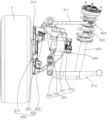
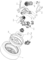
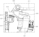
도 1은 본 발명의 일 실시예에 따른 차량용 코너 모듈 장치의 구성을 개략적으로 나타내는 사시도이고, 도 2는 본 발명의 일 실시예에 따른 차량용 코너 모듈 장치의 구성을 개략적으로 나타내는 측면도이며, 도 3은 본 발명의 일 실시예에 따른 차량용 코너 모듈 장치의 구성을 개략적으로 나타내는 분해사시도이다.1 is a perspective view schematically showing the configuration of a corner module device for a vehicle according to an embodiment of the present invention, FIG. 2 is a side view schematically showing the configuration of a corner module device for a vehicle according to an embodiment of the present invention, and FIG. is an exploded perspective view schematically showing the configuration of a corner module device for a vehicle according to an embodiment of the present invention.
도 1, 도 2를 참조하면, 본 발명의 일 실시예에 따른 차량용 코너 모듈 장치(1)는 구동유닛(100), 제동유닛(200), 제1너클부(310), 제2너클부(320), 서스펜션유닛(400), 조향구동부(500), 조향각조절부(600)를 포함한다.1 and 2, the vehicle corner module device 1 according to an embodiment of the present invention includes a
구동유닛(100)은 차량의 휠(2)의 내측에 설치되고, 휠(2)에 구동력을 제공하여 휠(2)을 회전시킨다. 구동유닛(100)의 차량의 휠(2) 각각에 설치되어 복수개의 휠(2)에 개별적으로 구동력을 제공한다. 본 발명의 일 실시예에 따른 구동유닛(100)은 휠(2)의 내측에 고정되고, 차량의 배터리로부터 전원을 인가받아 자계를 형성하는 스테이터와, 휠(2)의 내측에 회전 가능하게 설치되고, 스테이터와의 전자기적 상호작용에 의해 휠(2)을 회전시키는 로터를 포함하여 구성될 수 있다. 스테이터와 로터는 중심축이 휠(2)의 중심축과 동일선상에 위치하고, 휠(2)의 내측에서 동심원상으로 상호 적층되도록 배치될 수 있다.The
제동유닛(200)은 휠(2)의 내측에 설치되고, 휠(2)의 회전에 간섭되어 제동력을 인가하거나 해제한다.The
본 발명의 일 실시예에 따른 제동유닛(200)은 브레이크 디스크(210), 브레이크 캘리퍼(220)를 포함한다.The
브레이크 디스크(210)는 휠(2) 또는 구동유닛(100)과 연결되고, 휠(2)의 회전에 연동되어 회전된다. 본 발명의 일 실시예에 따른 브레이크 디스크(210)는 원판 형상을 갖도록 형성되어 휠(2)의 내측에 설치된다. 브레이크 디스크(210)는 중심축이 휠(2)의 중심축과 동일선상에 위치하도록 배치된다. 브레이크 디스크(210)는 볼팅 등에 의해 휠(2) 또는 구동유닛(100)의 로터와 일체로 연결될 수 있다. 이에 따라 브레이크 디스크(210)는 휠(2)의 회전 시 휠(2)과 함께 중심축을 축으로 회전될 수 있다. 브레이크 디스크(210)의 직경은 휠(2)의 직경, 구동유닛(100)의 크기 등에 따라 다양하게 설계 변경이 가능하다.The
브레이크 캘리퍼(220)는 차량의 제동 시 브레이크 디스크(210)를 가압하여 제동력을 인가한다. 본 발명의 일 실시예에 따른 브레이크 캘리퍼(220)는 브레이크 디스크(210)와 마주보게 배치되는 브레이크 패드, 후술하는 제1너클부(310)에 결합되고, 브레이크 패드를 이동 가능하게 지지하는 캘리퍼 하우징 및 캘리퍼 하우징에 진퇴 이동 가능하게 설치되고, 이동 방향에 따라 브레이크 패드를 브레이크 디스크(210)로 향해 가압하거나 가압 해제하는 피스톤을 포함하여 구성될 수 있다. The
제1너클부(310)는 구동유닛(100)과 결합되고, 후술하는 조향각조절부(600)의 휠(2)에 대한 기계적인 연결을 제공하여 조향의 중심축인 킹핀축을 지지하는 구성으로서 기능한다. 본 발명의 일 실시예에 따른 제1너클부(310)는 볼팅 등에 의해 구동유닛(100)의 스테이터에 결합되어 지지될 수 있다. 제1너클부(310)는 휠베어링 등을 매개로 구동유닛(100)의 로터를 회전 가능하게 지지할 수 있다. 제1너클부(310)는 충분한 강성을 확보하기 위해 금속 계열의 소재를 주물 등으로 성형하여 제작될 수 있다. 제1너클부(310)의 구체적인 형상은 도 1, 도 2에 도시된 형상에 한정되는 것은 아니고, 구동유닛(100)과 결합되어 휠(2)의 내측면과 마주보게 배치될 수 있는 형상의 기술사상 안에서 다양한 설계 변경이 가능하다. The
제2너클부(320)는 제1너클부(310)와 이격되게 배치되고, 후술하는 조향구동부(500)와 조향각조절부(600)를 전체적으로 지지함과 동시에 서스펜션유닛(300)의 차체에 대한 기계적인 연결을 제공하여 휠(2)의 범프 및 리바운드 시 상하 운동을 하는 서스펜션 축을 지지하는 구성으로서 기능한다. 제2너클부(320)는 제1너클부(310)와 차량의 폭 방향으로 소정 간격 이격되어 마주보게 배치된다. 이에 따라 제1너클부(310)와 제2너클부(320)는 제2너클부(320)에 형성된 서스펜션 축과, 제1너클부(310)에 형성된 킹핀축을 차량의 폭 방향으로 상호 분리시킴으로써, 킹핀축을 휠(2)과 근접한 위치에 배치시켜 킹핀 오프셋 값을 감소시킬 수 있고, 차량의 주행 및 제동 안정성을 향상시킬 수 있다.The
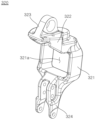
도 4는 본 발명의 일 실시예에 따른 제2너클부의 구성을 개략적으로 나타내는 사시도이다.4 is a perspective view schematically illustrating a configuration of a second knuckle part according to an embodiment of the present invention.
도 4를 참조하면, 본 발명의 일 실시예에 따른 제2너클부(320)는 바디부(321), 마운팅부(322), 제1연결부(323), 제2연결부(324)를 포함한다. Referring to FIG. 4 , the
바디부(321)는 제2너클부(320)의 중앙부 외관을 형성하고, 후술하는 마운팅부(322), 제1연결부(323), 제2연결부(324)를 전체적으로 지지한다. 본 발명의 일 실시예에 따른 바디부(321)에는 바디부(321)를 차량의 폭 방향으로 관통하는 홀 형태의 수용부(321a)가 구비될 수 있다. 이에 따라 바디부(321)는 대략 중공형의 사각틀의 형태를 갖도록 형성될 수 있다. 수용부(321a)에는 후술하는 조향구동부(500)가 삽입되고, 바디부(321)는 수용부(321a)로 삽입된 조향구동부(500)와 용접, 볼팅 등에 의해 결합되어 조향구동부(500)를 지지한다. 바디부(321)는 후술하는 조향각조절부(600)의 출력축(614)이 킹핀축과 나란하게 배치되도록 지면에 대해 소정 각도 경사지게 배치될 수 있다.The
마운팅부(322)는 바디부(321)의 일측으로부터 연장되어 제2너클부(320)의 일측 외관을 형성한다. 마운팅부(322)는 후술하는 조향각조절부(600)와 결합되어 조향각조절부(600)를 지지한다. 본 발명의 일 실시예에 따른 마운팅부(322)는 바디부(321)의 상단부로부터 휠(2)을 향해 연장된다. 마운팅부(322)의 하측면은 조향각조절부(600)의 감속부(610)의 상측면이 안착될 수 있도록 형성된다. 마운팅부(322)는 하측면에 감속부(610)의 상측면이 안착된 상태에서 볼팅 결합 등에 의해 감속부(610)와 일체로 결합됨에 따라 조향각조절부(600)를 지지한다.The mounting
제1연결부(323)는 마운팅부(322)로부터 연장되고, 서스펜션유닛(400)에 구비되는 제1암(411)과 연결된다. 본 발명의 일 실시예에 따른 제1연결부(323)는 마운팅부(322)의 상측면으로부터 상방으로 돌출되는 고리의 형태를 갖도록 형성될 수 있다. 제1연결부(323)는 부시, 볼조인트, 핀 등을 매개로 서스펜션유닛(400)에 구비되는 제1암(411)의 일단과 연결될 수 있다. 제1연결부(323)는 제1암(411)의 일단을 회전 가능하게 지지하여 휠(2)의 범프 및 리바운드 시 상하 운동을 하는 서스펜션 축의 상단 기준점으로서 기능한다.The
제2연결부(324)는 바디부(321)의 타측으로부터 연장되어 제2너클부(320)의 타측 외관을 형성한다. 제2연결부(324)는 서스펜션유닛(400)에 구비되는 제2암(412)과 연결된다. 본 발명의 일 실시예에 따른 제2연결부(324)는 바디부(321)의 하단부로부터 하방으로 연장되는 한 쌍의 막대 형태를 갖도록 형성될 수 있다. 제2연결부(324)는 부시, 볼조인트, 핀 등을 매개로 서스펜션유닛(400)에 구비되는 제2암(412)의 일단과 연결될 수 있다. 제2연결부(324)는 제2암(412)의 일단을 회전 가능하게 지지하여 휠(2)의 범프 및 리바운드 시 상하 운동을 하는 서스펜션 축의 하단 기준점으로서 기능한다.The
제1연결부(323)와 제2연결부(324)는 지면에 대해 수직한 방향으로 나란하게 배치된다. 이에 따라 제1연결부(323)와 제2연결부(324)는 서스펜션 축의 방향을 휠(2)의 범프 및 리바운드의 운동 방향과 나란하게 배치시킬 수 있다. The
서스펜션유닛(400)은 제2너클부(320)와 연결되고, 차체에 대해 제2너클부(320)를 지지한다. 서스펜션유닛(400)은 차량의 주행 시 휠(2)을 통해 노면으로부터 전달되는 충격을 흡수할 수 있도록 구비된다. 여기서 차체는 차량의 하방에 설치되는 서브프레임(미도시) 등과 같은 샤시프레임으로 예시될 수 있다.The
본 발명의 일 실시예에 따른 서스펜션유닛(400)은 서스펜션암(410), 쇽업소버(420)를 포함한다.A
서스펜션암(410)은 제2너클부(320)와 차체 사이에 구비되어 제2너클부(320)를 지지한다. 보다 구체적으로, 서스펜션암(410)은 제2너클부(320)를 매개로 휠(2)을 차체와 연결시킴과 동시에 자체적인 강성에 의해 차량의 주행 중 휠(2)로부터 가해지는 하중을 흡수하며, 휠(2)의 움직임을 조절하는 역할을 수행한다.The
본 발명의 일 실시예에 따른 서스펜션암(410)은 제1암(411), 제2암(412)을 포함할 수 있다. The
제1암(411)과 제2암(412)은 상하 방향으로 이격되어 마주보게 배치된다. 제1암(411)은 일단이 제1연결부(323)에 회전 가능하게 연결되고, 타단이 차체에 회전 가능하게 연결된다. 제2암(412)은 제2연결부(324)에 회전 가능하게 연결되고, 타단이 차체에 회전 가능하게 연결된다. 이 경우, 제1암(411)과 제2암(412)은 부시, 볼조인트, 핀 등을 매개로 양단이 각각 제1연결부(323) 또는 제2연결부(324)와 차체에 회전 가능하게 지지될 수 있다. 제1암(411)과 제2암(412)은 더블위시본 형태를 갖도록 형성될 수 있다. 이에 따라 제1암(411)과 제2암(412)은 휠(2)의 네거티브 캠버 설정이 가능해져 차량의 코너링 성능을 향상시킬 수 있고, 차고를 낮추는 저상화 설정이 가능해질 수 있다.The
쇽업소버(420)는 길이 방향을 따라 신축 가능하게 구비되어 노면으로부터 휠(2)을 통해 차체로 전달되는 충격 또는 진동을 흡수한다. 본 발명의 일 실시예에 따른 쇽업소버(420)는 실린더(421), 로드(422), 탄성체(423)를 포함한다.The
실린더(421)는 상하 방향으로 연장되며 내부에 유체가 충진된다. 실린더(421)는 하단부가 제1암(411)을 관통하여 제2암(412)의 상측면에 회전 가능하게 연결될 수 있다.The
로드(422)는 실린더(421)의 길이 방향을 따라 연장된다. 로드(422)는 하측이 실린더(421)의 상단부로 삽입되어 실린더(421)의 길이 방향을 따라 슬라이드 이동 가능하게 설치된다. 로드(422)는 타측이 조향본체(2410)에 볼팅 등에 의해 결합된다. 로드(422)는 실린더(421) 내부에 충진된 유체의 압력에 연동되어 실린더(421)의 길이 방향을 따라 슬라이드 이동된다. The
탄성체(423)는 실린더(421) 및 로드(422)의 외측면을 감싸도록 배치되고, 로드(422)의 슬라이드 이동에 연동되어 길이가 가변된다. 본 발명의 일 실시예에 따른 탄성체(423)는 길이 방향을 따라 신축 가능한 코일 스프링의 형태를 갖도록 형성될 수 있다. 탄성체(423)는 양단부가 각각 실린더(421)에 고정되는 하부 시트 및 로드(422)에 고정되는 상부 시트에 결합되어 지지될 수 있다. 탄성체(423)는 로드(422)의 슬라이드 이동 시 압축 또는 인장되며 탄성복원력을 축적하고, 축적된 탄성복원력에 의해 노면으로부터 인가되는 충격을 상쇄시킬 수 있다.The
조향구동부(500)는 제2너클부(320)에 설치되어 조향력을 생성한다. The
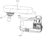
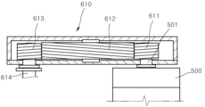
도 5는 본 발명의 일 실시예에 따른 조향구동부와 조향각조절부의 구성을 개략적으로 나타내는 사시도이고, 도 6은 본 발명의 일 실시예에 따른 조향구동부와 조향각조절부의 구성을 개략적으로 나타내는 단면도이다.5 is a perspective view schematically showing the configuration of a steering drive unit and a steering angle control unit according to an embodiment of the present invention, and FIG. 6 is a cross-sectional view schematically showing the configuration of a steering drive unit and a steering angle control unit according to an embodiment of the present invention.
도 1 내지 도 6을 참조하면, 본 발명의 일 실시예에 따른 조향구동부(500)는 외부로부터 인가되는 전원으로부터 회전력을 발생시키는 다양한 종류의 전동 모터로 예시될 수 있다. 조향구동부(500)는 수용부(321a)의 내부로 삽입되고, 용접 또는 볼팅 등에 의해 바디부(321)와 일체로 결합되어 지지된다. 조향구동부(500)는 차량의 배터리와 연결되어 배터리로부터 전원을 공급받을 수 있다. 조향구동부(500)는 차량의 ECU 등과 연결되고, ECU의 제어 신호에 의해 회전력의 발생 여부, 회전력의 방향 등이 제어될 수 있다.Referring to FIGS. 1 to 6 , the
조향구동부(500)에는 조향구동부(500)로부터 발생되는 회전력을 후술하는 조향각조절부(600)로 전달하는 입력축(501)이 구비된다. 본 발명의 일 실시예에 따른 입력축(501)은 대략 막대 형상을 갖도록 형성되어 조향구동부(500)의 상단부로부터 마운팅부(322)를 향해 돌출된다. The
조향각조절부(600)는 제1너클부(310)와 연결되고, 조향구동부(500)로부터 생성되는 조향력에 연동되어 휠(2)의 조향각을 조절한다.The steering
본 발명의 일 실시예에 따른 조향각조절부(600)는 감속부(610), 조인트부(620)를 포함한다.The steering
감속부(610)는 제2너클부(320)에 결합되어 지지된다. 보다 구체적으로, 감속부(610)는 상측면이 마운팅부(322)의 하측면에 안착되고, 볼팅 결합 등에 의해 마운팅부(322)와 일체로 결합되어 지지된다. 감속부(610)는 조향구동부(500)로부터 생성되는 조향력을 감속하여 출력한다. 즉, 감속부(610)는 조향구동부(500)의 동작에 연동되어 회전되는 입력축(501)의 회전 속도를 설정된 감속비로 감속하여 휠(2)로 전달되는 조향력의 크기를 증폭시킬 수 있도록 구비된다.The
본 발명의 일 실시예에 따른 감속부(610)는 제1전달기어부(611), 제2전달기어부(612), 제3전달기어부(613)를 포함한다.The
제1전달기어부(611)는 조향구동부(500)의 입력축(501)과 함께 회전된다. 본 발명의 일 실시예에 따른 제1전달기어부(611)는 외주면에 웜나사산이 구비된 웜축의 형태를 갖도록 형성될 수 있다. 이에 따라 제1전달기어부(611)는 제2전달기어부(612)와 맞물린 경우, 제2전달기어부(612)로부터 전달되는 회전력에 의해 역회전되는 것이 방지될 수 있어 휠(2)의 조향각이 임의로 가변되는 것을 방지할 수 있다. 제1전달기어부(611) 외주면에 형성된 웜나사산은 피치경이 제1전달기어부(611)의 축 방향을 따라 가변될 수 있다. 제1전달기어부(611)는 도 6에 도시된 바와 같이 입력축(501)이 중심축을 직접 관통하여 삽입됨에 따라 중심축이 입력축(501)과 평행하게 배치될 수 있고, 별도의 기어 연결 구조를 통해 입력축(501)과 수직하게 배치되는 것도 가능하다.The first
제2전달기어부(612)는 제1전달기어부(611)와 맞물려 결합되고, 제1전달기어부(611)의 회전에 연동되어 회전된다. 본 발명의 일 실시예에 따른 제2전달기어부(612)는 중심축의 방향이 입력축(501)과 평행하게 배치된다. 제2전달기어부(612)는 도 6에 도시된 바와 같이 외주면에 제1전달기어부(611)에 형성된 웜나사산에 공액이 되는 나선형의 치형을 갖도록 형성될 수 있다. 제2전달기어부(612)의 외주면에 형성된 치형은 피치경이 제2전달기어부(612)의 축 방향을 따라 가변될 수 있다. The second
이와 달리 제2전달기어부(612)는 제1전달기어부(611)가 입력축(501)과 수직하게 배치되는 경우, 중심축이 입력축(501)과 평행하게 배치되고, 제1전달기어부(611)의 웜나사산과 맞물려 결합되는 통상적인 웜휠의 형태를 갖도록 형성되는 것도 가능하다.In contrast, when the second
제3전달기어부(613)는 제2전달기어부(612)와 맞물려 결합되고, 제2전달기어부(612)의 회전에 연동되어 출력축(614)을 회전시킨다. 본 발명의 일 실시예에 따른 제3전달기어부(613)는 중심축의 방향이 입력축(501)과 평행하게 배치되고, 출력축(614)이 중심축을 관통하여 삽입된다. 이에 따라 출력축(614)은 중심축이 입력축(501)과 평행하게 배치되며, 제3전달기어부(613)와 일체로 회전될 수 있다. 출력축(614)은 제3전달기어부(613)는 도 6에 도시된 바와 같이 외주면에 제2전달기어부(612)에 형성된 치형에 공액이 되는 나선형의 치형을 갖도록 형성될 수 있다. 제3전달기어부(613)의 외주면에 형성된 치형은 피치경이 제3전달기어부(613)의 축 방향을 따라 가변될 수 있다.The third
이와 달리 제3전달기어부(613)는 제2전달기어부(612)가 웜휠의 형태로 형성되는 경우, 제2전달기어부(612)의 외주면에 맞물려 결합되는 통상적인 헬리컬기어, 스퍼기어 등의 형태를 갖도록 형성되는 것도 가능하다. In contrast, when the second
조인트부(620)는 제2너클부(320)와 제1너클부(310)의 기계적인 연결을 제공함과 동시에 감속부(510)로부터 출력되는 조향력을 제1너클부(310)로 최종적으로 전달하여 휠(2)의 조향각을 가변시킨다.The
본 발명의 일 실시예에 따른 조인트부(620)는 제1조인트(621), 제2조인트(622)를 포함한다.The
제1조인트(621)는 출력축(614)으로부터 연장되고, 제1너클부(310)의 일측에 연결된다. 제1조인트(621)는 조향구동부(500)로부터 생성된 조향력을 최종적으로 제1너클부(310)로 전달한다. 이 경우, 제1조인트(621)는 휠(2)의 조향 동작 시 휠(2)이 회전하는 중심축이 되는 킹핀축의 상단 기준점으로서 기능한다. The first joint 621 extends from the
도 7은 본 발명의 일 실시예에 따른 제1조인트의 구성을 개략적으로 나타내는 확대도이다.7 is an enlarged view schematically showing the configuration of a first joint according to an embodiment of the present invention.
도 1 내지 도 7을 참조하면, 본 발명의 일 실시예에 따른 제1조인트(621)는 양측이 각각 출력축(614)의 하단부와 제1너클부(310)의 상측에 연결된다. 제1조인트(621)는 휠(2)의 상하 거동에 따른 출력축(614)과 제1너클부(310)의 절각을 일부 허용함과 동시에 출력축(614)과 제1너클부(310)가 동일한 각속도로 회전될 수 있도록 다양한 종류의 등속 조인트로 예시될 수 있다. 1 to 7 , both sides of the first joint 621 according to an embodiment of the present invention are connected to the lower end of the
제2조인트(622)는 제2너클부(320)로부터 연장되고, 제1너클부(310)의 타측에 연결된다. 제2조인트(622)는 제1조인트(621)와 차량의 높이 방향을 따라 상하로 이격되게 배치된다. 제2조인트(622)는 휠(2)의 조향 동작 시 휠(2)이 회전하는 중심축이 되는 킹핀축의 하단 기준점으로서 기능한다. 이에 따라 제2조인트(622)는 제1조인트(621)로부터 전달되는 조향력에 의해 제1너클부(310)가 회전되는 경우, 제1너클부(310)의 하측이 킹핀축을 유지하며 회전될 수 있도록 유도할 수 있다. The second joint 622 extends from the
도 8은 본 발명의 일 실시예에 따른 제2조인트의 구성을 개략적으로 나타내는 확대도이다.8 is an enlarged view schematically showing the configuration of a second joint according to an embodiment of the present invention.
도 1 내지 도 8을 참조하면, 본 발명의 일 실시예에 따른 제2조인트(622)는 제2너클부(320)의 하단부에 연결되고, 제1너클부(310)를 향해 연장되는 연장암(622a)의 단부에 결합되어 지지될 수 있다. 제2조인트(622)는 제1조인트(621)와 차량의 높이 방향을 따라 상하로 이격되어 제1너클부(310)의 하측에 연결된다. 제2조인트(622)는 제1조인트(621)와 마찬가지로 다양한 종류의 등속 조인트로 예시될 수 있다. 1 to 8, the second joint 622 according to an embodiment of the present invention is connected to the lower end of the
제1조인트(621)와 제2조인트(622)는 킹핀축이 일정한 크기의 킹핀 경사각을 이룰 수 있도록 지면에 대해 소정 각도 경사지게 배치된다.The first joint 621 and the second joint 622 are disposed inclined at a predetermined angle with respect to the ground so that the kingpin axis can form a kingpin inclination angle of a predetermined size.
본 발명은 도면에 도시된 실시예를 참고로 하여 설명되었으나, 이는 예시적인 것에 불과하며 당해 기술이 속하는 기술분야에서 통상의 지식을 가진 자라면 이로부터 다양한 변형 및 균등한 타 실시예가 가능하다는 점을 이해할 것이다. 따라서, 본 발명의 진정한 기술적 보호범위는 아래의 특허청구범위에 의하여 정해져야할 것이다.Although the present invention has been described with reference to the embodiments shown in the drawings, it should be noted that this is only exemplary and various modifications and equivalent other embodiments are possible from those skilled in the art to which the technology pertains. will understand Therefore, the true technical protection scope of the present invention will be defined by the claims below.
1 : 차량용 코너 모듈 장치
2 : 휠
100 : 구동유닛
200 : 제동유닛
210 : 브레이크 디스크
220 : 브레이크 캘리퍼
310 : 제1너클부
320 : 제2너클부
321 : 바디부
321a : 수용부
322 : 마운팅부
323 : 제1연결부
324 : 제2연결부
400 : 서스펜션유닛
410 : 서스펜션암
411 : 제1암
412 : 제2암
420 : 쇽업소버
421 : 실린더
422 : 로드
423 : 탄성체
500 : 조향구동부
501 : 입력축
600 : 조향각조절부
610 : 감속부
611 : 제1전달기어부
612 : 제2전달기어부
613 : 제3전달기어부
614 : 출력축
620 : 조인트부
621 : 제1조인트
622 : 제2조인트1: vehicle corner module device 2: wheel
100: driving unit 200: braking unit
210: brake disc 220: brake caliper
310: first knuckle part 320: second knuckle part
321:
322: mounting part 323: first connection part
324: second connection part 400: suspension unit
410: suspension arm 411: first arm
412: second arm 420: shock absorber
421: cylinder 422: rod
423: elastic body 500: steering drive unit
501: input shaft 600: steering angle control unit
610: reduction part 611: first transmission gear part
612: second transmission gear unit 613: third transmission gear unit
614: output shaft 620: joint part
621: first joint 622: second joint
Claims (9)
상기 구동유닛과 결합되는 제1너클부;
상기 제1너클부와 상기 차량의 폭 방향으로 이격되어 마주보게 배치되는 제2너클부;
상기 제2너클부에 연결되고, 차체에 대해 상기 제2너클부를 지지하는 서스펜션유닛;
상기 제2너클부에 설치되어 조향력을 생성하는 조향구동부; 및
상기 제1너클부와 연결되고, 상기 조향구동부로부터 생성되는 조향력에 연동되어 상기 휠의 조향각을 조절하는 조향각조절부;를 포함하는 것을 특징으로 하는 차량용 코너 모듈 장치.
a driving unit installed inside a wheel of a vehicle and providing a driving force to the wheel;
a first knuckle portion coupled to the driving unit;
a second knuckle part disposed to face the first knuckle part and spaced apart from each other in the width direction of the vehicle;
a suspension unit connected to the second knuckle part and supporting the second knuckle part with respect to the vehicle body;
a steering drive unit installed in the second knuckle unit to generate a steering force; and
and a steering angle adjusting unit connected to the first knuckle unit and interlocked with the steering force generated from the steering driving unit to adjust the steering angle of the wheel.
상기 제2너클부는,
상기 제1너클부와 마주보게 배치되고, 상기 조향구동부가 삽입되는 수용부가 구비되는 바디부;
상기 바디부의 일측으로부터 연장되고, 상기 조향각조절부를 지지하는 마운팅부;
상기 마운팅부로부터 연장되고, 상기 서스펜션유닛에 구비되는 제1암과 연결되는 제1연결부; 및
상기 바디부의 타측으로부터 연장되고, 상기 서스펜션유닛에 구비되는 제2암과 연결되는 제2연결부;를 포함하는 것을 특징으로 하는 차량용 코너 모듈 장치.
According to claim 1,
The second knuckle part,
a body portion disposed to face the first knuckle portion and provided with an accommodating portion into which the steering driving portion is inserted;
a mounting portion extending from one side of the body portion and supporting the steering angle adjusting portion;
a first connection portion extending from the mounting portion and connected to a first arm provided in the suspension unit; and
A corner module device for a vehicle comprising: a second connection portion extending from the other side of the body portion and connected to a second arm provided in the suspension unit.
상기 제1연결부와 상기 제2연결부는 지면에 대해 수직한 방향으로 나란하게 배치되는 것을 특징으로 하는 차량용 코너 모듈 장치.
According to claim 2,
The corner module device for a vehicle, characterized in that the first connection part and the second connection part are arranged side by side in a direction perpendicular to the ground.
상기 조향각조절부는,
상기 제2너클부에 결합되고, 상기 조향구동부로부터 생성되는 조향력을 감속하여 출력하는 감속부; 및
상기 감속부로부터 출력되는 조향력을 상기 제1너클부로 전달하여 상기 휠의 조향각을 가변시키는 조인트부;를 포함하는 것을 특징으로 하는 차량용 코너 모듈 장치.
According to claim 1,
The steering angle control unit,
a deceleration unit coupled to the second knuckle unit and decelerating and outputting steering force generated from the steering driving unit; and
and a joint part that transmits the steering force output from the deceleration part to the first knuckle part to vary the steering angle of the wheel.
상기 감속부는,
상기 조향구동부의 입력축과 함께 회전되는 제1전달기어부;
상기 제1전달기어부와 맞물려 결합되고, 상기 제1전달기어부의 회전에 연동되어 회전되는 제2전달기어부; 및
상기 제2전달기어부와 맞물려 결합되고, 상기 제2전달기어부의 회전에 연동되어 출력축을 회전시키는 제3전달기어부;를 포함하는 것을 특징으로 하는 차량용 코너 모듈 장치.
According to claim 4,
The deceleration part,
a first transmission gear part that rotates together with the input shaft of the steering drive part;
a second transmission gear unit engaged with the first transmission gear unit and rotated in conjunction with the rotation of the first transmission gear unit; and
and a third transmission gear unit engaged with the second transmission gear unit and rotating an output shaft in conjunction with rotation of the second transmission gear unit.
상기 제1전달기어부는 외주면에 웜나사산이 구비된 웜축의 형태를 갖도록 형성되는 것을 특징으로 하는 차량용 코너 모듈 장치.
According to claim 5,
The first transmission gear unit is a corner module device for a vehicle, characterized in that formed to have a shape of a worm shaft having a worm thread on an outer circumferential surface.
상기 조인트부는,
상기 출력축으로부터 연장되고, 상기 제1너클부의 일측에 연결되는 제1조인트; 및
상기 제2너클부로부터 연장되고, 상기 제1조인트와 이격되게 배치되며, 상기 제1너클부의 타측에 연결되는 제2조인트;를 포함하는 것을 특징으로 하는 차량용 코너 모듈 장치.
According to claim 5,
The joint part,
a first joint extending from the output shaft and connected to one side of the first knuckle part; and
and a second joint extending from the second knuckle part, disposed to be spaced apart from the first joint, and connected to the other side of the first knuckle part.
상기 제1조인트와 상기 제2조인트는 지면에 대해 소정 각도 경사지게 배치되는 것을 특징으로 하는 차량용 코너 모듈 장치.
According to claim 7,
The corner module device for a vehicle, characterized in that the first joint and the second joint are disposed inclined at a predetermined angle with respect to the ground.
상기 제1조인트와 상기 제2조인트는 등속 조인트인 것을 특징으로 하는 차량용 코너 모듈 장치.According to claim 7,
The corner module device for a vehicle, characterized in that the first joint and the second joint are constant velocity joints.
Priority Applications (4)
| Application Number | Priority Date | Filing Date | Title |
|---|---|---|---|
| KR1020220014080A KR20230117841A (en) | 2022-02-03 | 2022-02-03 | Corner module apparatus for vehicle |
| US18/080,974 US12409692B2 (en) | 2022-02-03 | 2022-12-14 | Corner module apparatus for vehicle |
| CN202211633479.3A CN116534114B (en) | 2022-02-03 | 2022-12-19 | Vehicle turning module equipment |
| EP22214408.1A EP4223564B1 (en) | 2022-02-03 | 2022-12-19 | Corner module apparatus for a vehicle |
Applications Claiming Priority (1)
| Application Number | Priority Date | Filing Date | Title |
|---|---|---|---|
| KR1020220014080A KR20230117841A (en) | 2022-02-03 | 2022-02-03 | Corner module apparatus for vehicle |
Publications (1)
| Publication Number | Publication Date |
|---|---|
| KR20230117841A true KR20230117841A (en) | 2023-08-10 |
Family
ID=87560795
Family Applications (1)
| Application Number | Title | Priority Date | Filing Date |
|---|---|---|---|
| KR1020220014080A Pending KR20230117841A (en) | 2022-02-03 | 2022-02-03 | Corner module apparatus for vehicle |
Country Status (1)
| Country | Link |
|---|---|
| KR (1) | KR20230117841A (en) |
Cited By (1)
| Publication number | Priority date | Publication date | Assignee | Title |
|---|---|---|---|---|
| CN118753370A (en) * | 2024-08-09 | 2024-10-11 | 吉林大学 | A dual-tandem steering suspension integrated module based on linear rotary motor |
-
2022
- 2022-02-03 KR KR1020220014080A patent/KR20230117841A/en active Pending
Cited By (1)
| Publication number | Priority date | Publication date | Assignee | Title |
|---|---|---|---|---|
| CN118753370A (en) * | 2024-08-09 | 2024-10-11 | 吉林大学 | A dual-tandem steering suspension integrated module based on linear rotary motor |
Similar Documents
| Publication | Publication Date | Title |
|---|---|---|
| EP4223564B1 (en) | Corner module apparatus for a vehicle | |
| CN101287616B (en) | In-wheel suspension | |
| US7938210B2 (en) | Wheel-embedded suspension | |
| CN112368160B (en) | In-wheel three-arm suspension for vehicles | |
| WO2022134087A1 (en) | Suspension structure, angle module system and motor vehicle | |
| JP2000233619A (en) | Assembly provided with wheel and suspension integrally formed with wheel | |
| JP2020111270A (en) | Steering device and vehicle wheel mounting module including the same | |
| KR20240062711A (en) | Corner module apparatus for vehicle | |
| JP2022177048A (en) | Suspension system and steering capability | |
| KR20230142925A (en) | Suspension apparatus for vehicle | |
| US20240124058A1 (en) | Corner module apparatus for vehicle | |
| CN111032374B (en) | Wheel suspension for motor vehicles | |
| WO2012133245A1 (en) | In-wheel motor apparatus | |
| US20240400127A1 (en) | Corner module apparatus for vehicle | |
| JP2023160024A (en) | vehicle suspension equipment | |
| EP4467364B1 (en) | Corner module apparatus | |
| KR20230117841A (en) | Corner module apparatus for vehicle | |
| US11364761B2 (en) | Vehicle suspension device | |
| KR20230117842A (en) | Corner module apparatus for vehicle | |
| KR20240051593A (en) | Corner module apparatus for vehicle | |
| KR102632583B1 (en) | a steering system for a vehicle | |
| CN221642546U (en) | Corner module equipment for vehicles | |
| CN223574196U (en) | Modularized driving steering and hanging integrated bridge | |
| KR102580457B1 (en) | an control apparatus of position for a vehicle | |
| KR20240171817A (en) | Corner module apparatus for vehicle |
Legal Events
| Date | Code | Title | Description |
|---|---|---|---|
| PA0109 | Patent application |
St.27 status event code: A-0-1-A10-A12-nap-PA0109 |
|
| R18-X000 | Changes to party contact information recorded |
St.27 status event code: A-3-3-R10-R18-oth-X000 |
|
| PG1501 | Laying open of application |
St.27 status event code: A-1-1-Q10-Q12-nap-PG1501 |
|
| A201 | Request for examination | ||
| D21 | Rejection of application intended |
Free format text: ST27 STATUS EVENT CODE: A-1-2-D10-D21-EXM-PE0902 (AS PROVIDED BY THE NATIONAL OFFICE) |
|
| PE0902 | Notice of grounds for rejection |
St.27 status event code: A-1-2-D10-D21-exm-PE0902 |