KR20230096997A - mechanical pencil - Google Patents
mechanical pencil Download PDFInfo
- Publication number
- KR20230096997A KR20230096997A KR1020237013080A KR20237013080A KR20230096997A KR 20230096997 A KR20230096997 A KR 20230096997A KR 1020237013080 A KR1020237013080 A KR 1020237013080A KR 20237013080 A KR20237013080 A KR 20237013080A KR 20230096997 A KR20230096997 A KR 20230096997A
- Authority
- KR
- South Korea
- Prior art keywords
- rotor
- cam
- rotation
- knock
- mechanical pencil
- Prior art date
Links
Images


Classifications
-
- B—PERFORMING OPERATIONS; TRANSPORTING
- B43—WRITING OR DRAWING IMPLEMENTS; BUREAU ACCESSORIES
- B43K—IMPLEMENTS FOR WRITING OR DRAWING
- B43K21/00—Propelling pencils
- B43K21/02—Writing-core feeding mechanisms
- B43K21/16—Writing-core feeding mechanisms with stepwise feed of writing-cores
-
- B—PERFORMING OPERATIONS; TRANSPORTING
- B43—WRITING OR DRAWING IMPLEMENTS; BUREAU ACCESSORIES
- B43K—IMPLEMENTS FOR WRITING OR DRAWING
- B43K21/00—Propelling pencils
- B43K21/02—Writing-core feeding mechanisms
- B43K21/22—Writing-cores gripping means, e.g. chucks
Abstract
축통(11) 내에 배치된 척 유닛(20)의 전후 이동에 의해 필기심의 해제 및 파지를 행함으로써, 필기심을 전방으로 조출하도록 구성되고, 척 유닛(20)이, 필기심을 파지한 상태에서 중심축선 둘레로 회전 가능하게 되도록 축통(11) 내에 유지되는 제1 샤프 펜슬(1)이, 회전자(30)를 가지고, 필기심이 받는 필기압에 의한 척 유닛(20)의 후퇴 동작에 수반하여 회전자(30)가 후퇴하여, 회전자(30)를 회전 운동시키는 회전 구동 기구(22)를 구비하고, 회전자(30)의 회전 운동이 척 유닛(20)을 매개로 하여 필기심에 전달되도록 구성되고, 회전자(30)의 회전을 락하는 회전 락 기구를 더 구비한다. The writing lead is released and gripped by the back and forth movement of the chuck unit 20 disposed in the barrel 11, so that the writing lead is drawn forward, and the chuck unit 20 moves along the central axis line in a state where the writing lead is held. The first mechanical pencil 1 held in the barrel 11 so as to be able to rotate around has a rotor 30, and the chuck unit 20 moves backward due to the writing pressure applied to the writing lead so that the rotor rotates. 30 is retracted, and the rotor 30 is provided with a rotational drive mechanism 22 that rotates the rotor 30, and the rotational motion of the rotor 30 is transmitted to the writing lead via the chuck unit 20 And, a rotation lock mechanism for locking the rotation of the rotor 30 is further provided.
Description
본 발명은 샤프 펜슬에 관한 것이다. The present invention relates to a mechanical pencil.
필기심의 전진을 허용하고 후퇴를 저지하는 척을 구비한 슬라이더를 포함하는 회전 부재와, 회전자를 가지고 또한 척에 파지된 필기심이 받는 필기압에 의한 축선 방향의 후퇴 동작 및 필기압의 해제에 의한 축선 방향의 전진 동작을 받아, 회전자를 일방향으로 회전 구동시키는 회전 구동 기구를 구비하고, 척이, 회전자의 회전 구동력을 받아 회전하는 것에 의해서, 필기심이 회전하도록 구성된 샤프 펜슬이 공지이다(특허문헌 1). A rotational member including a slider having a chuck for allowing advancement of a writing lead and preventing retraction, a retreating operation in an axial direction by a writing pressure applied to a writing lead held by a rotor and a writing lead held by the chuck, and release of the writing pressure A mechanical pencil having a rotation drive mechanism for rotationally driving a rotor in one direction in response to forward movement in an axial direction, and configured such that a writing lead rotates when a chuck rotates by receiving rotational driving force of the rotor is known (patented). Literature 1).
특허문헌 1에 기재된 샤프 펜슬에서는, 써 나감에 따라서 필기심이 회전하기 때문에, 필기심의 편마모를 방지할 수 있다. 한편으로, 회전 구동 기구에 의해서 필기심을 회전시키기 위해 미소(微小)하지만 필기심의 전진 및 후퇴도 행해지기 때문에, 예를 들어 속기(速記)하는 경우 등에 있어서, 이러한 필기심의 전진 및 후퇴가 번거롭게 느껴지는 경우가 있다. 따라서, 사용자가 회전 구동 기구의 온(가동 또는 유효화)과 오프(정지 또는 무효화)를 자유롭게 전환할 수 있도록 하는 것이 바람직하다. In the mechanical pencil described in Patent Literature 1, since the writing lead rotates as you write, uneven wear of the writing lead can be prevented. On the other hand, in order to rotate the writing lead by the rotational drive mechanism, the writing lead advances and retreats, albeit in a small way, for example, in the case of shorthand writing, etc., when such advances and retreats are cumbersome. there is Therefore, it is desirable to allow the user to freely switch between on (activation or activation) and off (stopping or inactivation) of the rotary drive mechanism.
본 발명은 회전 구동 기구의 온과 오프를 자유롭게 전환 가능한 샤프 펜슬을 제공하는 것을 목적으로 한다. An object of the present invention is to provide a mechanical pencil capable of freely switching on and off a rotation drive mechanism.
본 발명의 일 양태에 의하면, 축통(軸筒) 내에 배치된 척 유닛의 전후 이동에 의해 필기심의 해제 및 파지를 행함으로써, 상기 필기심을 전방으로 조출(繰出, 계속 내보냄)하도록 구성되고, 상기 척 유닛이, 상기 필기심을 파지한 상태에서 중심축선 둘레로 회전 가능하게 되도록 상기 축통 내에 유지되는 샤프 펜슬로서, 회전자를 가지고, 상기 필기심이 받는 필기압에 의한 상기 척 유닛의 후퇴 동작에 수반하여 상기 회전자가 후퇴하여, 상기 회전자를 회전 운동시키는 회전 구동 기구를 구비하고, 상기 회전자의 회전 운동이 상기 척 유닛을 매개로 하여 상기 필기심에 전달되도록 구성된 샤프 펜슬에 있어서, 상기 회전자의 회전을 락(lock)하는 회전 락 기구를 더 구비하는 것을 특징으로 하는 샤프 펜슬이 제공된다. According to one aspect of the present invention, the writing lead is released and gripped by forward and backward movement of a chuck unit disposed in a barrel, so that the writing lead is drawn out forward, and the chuck A mechanical pencil held in the barrel so that the unit is rotatable around a central axis while holding the writing lead, has a rotor, and moves the chuck unit to retract by the writing pressure applied to the writing lead, A mechanical pencil having a rotational drive mechanism for rotating the rotor by retracting the rotor, and transmitting the rotational motion of the rotor to the writing lead via the chuck unit, wherein the rotation of the rotor There is provided a mechanical pencil characterized in that it further comprises a rotation lock mechanism for locking.
본 발명의 다른 양태에 의하면, 상기 회전 락 기구가, 상기 회전자를 상기 회전 구동 기구에 있어서 상대적으로 후퇴한 상태에서 락하도록 구성되어 있어도 된다. 상기 회전 락 기구가, 상기 회전자를 후방으로 압압(押壓)하거나 또는 상기 회전 구동 기구를 전방으로 압압하여 상기 회전자를 상기 회전 구동 기구에 있어서 상대적으로 후퇴시키도록 구성되어 있어도 된다. According to another aspect of the present invention, the rotation lock mechanism may be configured to lock the rotor in a relatively retracted state in the rotation drive mechanism. The rotation lock mechanism may be configured to push the rotor backward or press the rotation drive mechanism forward to cause the rotor to move relatively backward in the rotation drive mechanism.
상기 회전자 또는 상기 회전 구동 기구가, 상기 회전 락 기구에 의해서 직접적 또는 간접적으로 압압되어 있어도 된다. 상기 회전 락 기구가 캠을 구비한 회전 부재를 가지고, 상기 회전 부재의 회전 운동이 상기 캠의 작용에 의해서 직진 운동으로 변환되어, 상기 회전자가 압압되어 있어도 된다. The rotor or the rotation drive mechanism may be directly or indirectly pressed by the rotation lock mechanism. The rotation lock mechanism may include a rotating member with a cam, and rotational motion of the rotating member may be converted into linear motion by an action of the cam, and the rotor may be pressed.
상기 회전자가 상기 척 유닛을 매개로 하여 후방으로 압압되어 있어도 된다. 상기 회전 락 기구가, 상기 회전 구동 기구를 전방으로 압압하는 출몰(出沒) 기구 또는 회전 조출 기구를 가지고 있어도 된다. The rotor may be pressed backward via the chuck unit. The rotation lock mechanism may have a protruding/retracting mechanism or a rotation drawing mechanism for pressing the rotation drive mechanism forward.
상기 출몰 기구 또는 상기 회전 조출 기구가, 스프링과, 상기 스프링을 가압하는 접동(摺動) 부재를 가지고, 상기 접동 부재를 전진시켜 상기 회전 구동 기구를 전방으로 압압해도 된다. The protruding/retracting mechanism or the rotary drawing/out mechanism may have a spring and a sliding member that urges the spring, and may advance the sliding member to press the rotary driving mechanism forward.
상기 출몰 기구가, 상기 축통의 후단부에 배치된 노크 부재와 노크 회전자를 더 가지고, 상기 노크 부재의 노크 조작을 행하여 상기 노크 회전자를 소정 위치까지 전진시키면, 상기 노크 회전자가 중심축선 둘레로 회전하여, 상기 노크 회전자의 후퇴가 멈춤과 아울러, 상기 회전 구동 기구를 전진시켜 상기 회전자가 상기 회전 구동 기구에 있어서 상대적으로 후퇴한 상태에서 락되도록 해도 된다. 상기 회전자가 스페이서를 매개로 하여 후방으로 압압되도록 해도 된다. The projecting/retracting mechanism further has a knock member and a knock rotor arranged at the rear end of the barrel, and when a knock operation of the knock member is performed to advance the knock rotor to a predetermined position, the knock rotor rotates around the central axis. It may be rotated to stop the retraction of the knock rotor, and the rotation drive mechanism may be advanced so that the rotor is locked in a relatively retracted state in the rotation drive mechanism. The rotor may be pressed backward via a spacer.
상기 회전 락 기구가 상기 회전자를 락한 상태에서, 상기 척 유닛을 전후 이동시키는 것에 의해서 상기 필기심이 조출되도록 해도 된다. 상기 회전 구동 기구가, 제1 캠 형성 부재 및 제2 캠 형성 부재를 가지고, 상기 회전자가 링 모양으로 형성되어 그 축선 방향의 일단면 및 타단면에 제1 캠면 및 제2 캠면이 각각 형성됨과 아울러, 상기 제1 캠면 및 상기 제2 캠면에 각각 대치하도록 상기 제1 캠 형성 부재 및 상기 제2 캠 형성 부재에 형성된 제1 고정 캠면 및 제2 고정 캠면이 배치되고, 상기 필기압에 의한 상기 척 유닛의 후퇴 동작에 의해서, 상기 회전자의 상기 제1 캠면이 상기 제1 고정 캠면에 맞닿아 서로 맞물려지고, 상기 필기압의 해제에 의해서, 상기 회전자의 상기 제2 캠면이 상기 제2 고정 캠면에 맞닿아 서로 맞물려지도록 구성되고, 상기 회전자의 상기 제1 캠면이, 상기 제1 고정 캠면에 서로 맞물려진 상태에 있어서, 상기 회전자의 상기 제2 캠면과 상기 제2 고정 캠면이, 축선 방향에 있어서 캠의 하나의 치(齒)에 대해서 위상이 어긋난 관계로 설정되고, 상기 회전자의 상기 제2 캠면이 상기 제2 고정 캠면에 서로 맞물려진 상태에 있어서, 상기 회전자의 상기 제1 캠면과 상기 제1 고정 캠면이 축선 방향에 있어서 캠의 하나의 치에 대해서 위상이 어긋난 관계로 설정되며, 상기 회전 구동 기구가, 상기 회전자에 있어서의 상기 제1 캠면을 상기 제1 고정 캠면에 서로 맞물리게 하여, 상기 회전자를 락하도록 해도 된다. The lead may be drawn out by moving the chuck unit back and forth in a state where the rotation lock mechanism locks the rotor. The rotation drive mechanism has a first cam forming member and a second cam forming member, the rotor is formed in a ring shape, and a first cam surface and a second cam surface are formed on one end surface and the other end surface in the axial direction, respectively. , a first fixed cam surface and a second fixed cam surface formed on the first cam forming member and the second cam forming member are disposed to face the first cam surface and the second cam surface, respectively, and the chuck unit by the writing pressure by the retracting operation, the first cam surface of the rotor abuts against and engages with the first fixed cam surface, and by releasing the writing pressure, the second cam surface of the rotor engages with the second fixed cam surface. configured to abut and engage with each other, and in a state in which the first cam surface of the rotor is engaged with the first fixed cam surface, the second cam surface and the second fixed cam surface of the rotor are in an axial direction In a state in which the phase is set in an out of phase relationship with respect to one tooth of the cam, and the second cam surface of the rotor is engaged with the second fixed cam surface, the first cam surface of the rotor and The first fixed cam surface is set to be out of phase with respect to one tooth of the cam in the axial direction, and the rotation drive mechanism engages the first cam surface of the rotor with the first fixed cam surface. Thus, the rotor may be locked.
본 발명의 양태에 의하면, 회전 구동 기구의 온과 오프를 자유롭게 전환 가능한 샤프 펜슬을 제공한다고 하는 공통된 효과를 달성한다. ADVANTAGE OF THE INVENTION According to the aspect of this invention, the common effect of providing the mechanical pencil which can freely switch ON and OFF of a rotary drive mechanism is achieved.
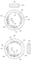
도 1은 제1 샤프 펜슬의 정면도이다.
도 2는 제1 샤프 펜슬의 종단면도이다.
도 3은 회전 구동 기구의 확대 단면도이다.
도 4는 회전 구동 기구의 회전자의 회전 구동을 설명하는 모식도이다.
도 5는 도 4에 이어지는 회전자의 회전 구동을 설명하는 모식도이다.
도 6은 제1 샤프 펜슬의 후축(後軸)의 종단면도이다.
도 7은 전환 스위치 및 제1 회전 부재의 분해 사시도이다.
도 8은 제1 회전 락 기구의 동작을 설명하는 종단면도이다.
도 9는 제2 샤프 펜슬의 종단면도이다.
도 10은 제2 회전 락 기구의 동작을 설명하는 종단면도이다.
도 11은 제3 샤프 펜슬의 종단면도이다.
도 12는 제3 샤프 펜슬의 후축의 후단부의 종단면도이다.
도 13은 제3 샤프 펜슬의 노크 부재의 사시도이다.
도 14는 제3 샤프 펜슬의 노크 회전자의 사시도이다.
도 15는 제3 회전 락 기구의 동작을 설명하는 모식도이다.
도 16은 제3 회전 락 기구의 동작을 설명하는 종단면도이다.
도 17은 제4 회전 락 기구의 동작을 설명하는 종단면도이다.
도 18은 제1 볼펜의 비(非)필기 상태에 있어서의 종단면도이다.
도 19는 제1 볼펜의 후축의 후단부의 종단면도이다.
도 20은 제1 볼펜의 제3 회전 부재의 사시도이다.
도 21은 제1 볼펜의 제1 접동 부재의 사시도이다.
도 22는 제1 볼펜의 비필기 상태에 있어서의 사시도이다.
도 23은 제1 볼펜의 필기 상태에 있어서의 사시도이다.
도 24는 제1 회전 조출 기구의 동작을 설명하는 횡단면도이다.
도 25는 제4 샤프 펜슬의 종단면도이다.
도 26은 제4 샤프 펜슬의 후축의 후단부의 종단면도이다.
도 27은 제4 샤프 펜슬의 제4 회전 부재의 사시도이다.
도 28은 제4 샤프 펜슬의 제2 접동 부재의 사시도이다.
도 29는 제2 회전 조출 기구의 동작을 설명하는 횡단면도이다.
도 30은 제5 회전 락 기구 및 제2 회전 조출 기구의 동작을 설명하는 종단면도이다.
도 31은 제6 회전 락 기구의 동작을 설명하는 종단면도이다. 1 is a front view of a first mechanical pencil.
2 is a longitudinal sectional view of a first mechanical pencil.
3 is an enlarged cross-sectional view of the rotary drive mechanism.
4 : is a schematic diagram explaining the rotation drive of the rotor of a rotation drive mechanism.
FIG. 5 is a schematic diagram illustrating rotational driving of the rotor following FIG. 4 .
Fig. 6 is a longitudinal sectional view of the rear shaft of the first mechanical pencil.
7 is an exploded perspective view of a changeover switch and a first rotating member.
Fig. 8 is a longitudinal sectional view explaining the operation of the first rotation lock mechanism.
9 is a longitudinal sectional view of a second mechanical pencil.
Fig. 10 is a longitudinal sectional view explaining the operation of the second rotation lock mechanism.
Fig. 11 is a longitudinal sectional view of a third mechanical pencil.
Fig. 12 is a longitudinal sectional view of the rear end of the rear shaft of the third mechanical pencil.
13 is a perspective view of a knock member of a third mechanical pencil.
14 is a perspective view of a knock rotor of a third mechanical pencil.
Fig. 15 is a schematic diagram explaining the operation of the third rotation lock mechanism.
Fig. 16 is a longitudinal sectional view explaining the operation of the third rotation lock mechanism.
Fig. 17 is a longitudinal sectional view explaining the operation of the fourth rotational lock mechanism.
Fig. 18 is a longitudinal sectional view of the first ballpoint pen in a non-writing state.
Fig. 19 is a longitudinal sectional view of the rear end of the rear shaft of the first ballpoint pen.
Fig. 20 is a perspective view of a third rotating member of the first ballpoint pen;
Fig. 21 is a perspective view of the first sliding member of the first ballpoint pen;
Fig. 22 is a perspective view of the first ballpoint pen in a non-writing state;
Fig. 23 is a perspective view of the first ballpoint pen in a writing state;
Fig. 24 is a cross-sectional view illustrating the operation of the first rotary drawing mechanism.
Fig. 25 is a longitudinal sectional view of a fourth mechanical pencil.
Fig. 26 is a longitudinal sectional view of the rear end of the rear shaft of the fourth mechanical pencil.
Fig. 27 is a perspective view of a fourth rotating member of a fourth mechanical pencil;
Fig. 28 is a perspective view of a second sliding member of a fourth mechanical pencil;
Fig. 29 is a cross-sectional view illustrating the operation of the second rotary drawing mechanism.
Fig. 30 is a longitudinal sectional view explaining the operation of the fifth rotary lock mechanism and the second rotary drawing mechanism.
Fig. 31 is a longitudinal sectional view explaining the operation of the sixth rotation lock mechanism;
이하, 도면을 참조하면서 본 발명의 실시 형태를 상세하게 설명한다. 모든 도면에 걸쳐, 대응하는 구성 요소에는 공통된 참조 부호를 붙인다. EMBODIMENT OF THE INVENTION Hereinafter, embodiment of this invention is described in detail, referring drawings. Throughout all figures, corresponding elements are given common reference numerals.
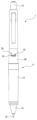
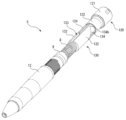
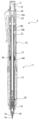
도 1은 제1 샤프 펜슬(1)의 정면도이고, 도 2는 제1 샤프 펜슬(1)의 종단면도이다. 1 is a front view of the first mechanical pencil 1 , and FIG. 2 is a longitudinal sectional view of the first mechanical pencil 1 .
제1 샤프 펜슬(1)은 통 모양으로 형성된 축통(11)을 가지고 있다. 축통(11)은 전축(12)과, 전축(12)의 후단부에 감합 또는 나사 결합하는 후축(40)과, 전축(12)의 전단부에 감합 또는 나사 결합하는 입구 부재(14)를 가지고 있다. 제1 샤프 펜슬(1)은 입구 부재(14)의 선단에 마련된 선단 파이프(16)로부터 필기심이 돌출하도록 구성되어 있다. 본 명세서에서는, 제1 샤프 펜슬(1)의 축선 방향에 있어서, 필기심측을 「전(前)」측으로 규정하고, 필기심측과는 반대측을 「후(後)」측으로 규정한다. The first mechanical pencil 1 has a
후축(40)의 전측의 측면에는, 둘레 방향을 따라서 연장되는 직사각형의 관통공(43)이 마련되어 있다. 관통공(43)으로부터는, 전환 스위치(50)의 스위치부(52)가 돌출되어 있다. 후축(40)의 후단부에는, 노크 커버(15)가 장착되고, 소거 부재로서의 지우개(17)를 덮고 있다. 축통(11)의 전단부의 내부에는, 슬라이더(18)가, 축선 방향으로 슬라이드 가능하고, 또한 중심축선 둘레로 회전 가능하게 배치되어 있다. 선단 파이프(16)는 슬라이더(18)에 장착되어 있다. 선단 파이프(16)의 후방의 슬라이더(18)의 내부에는, 중앙에 통공(通孔)이 형성된 유지 척(19)이 배치되어 있다. 유지 척(19)의 통공은, 필기심의 외주면에 슬라이드 접촉하고, 필기심을 일시적으로 유지하도록 작용한다. A rectangular through
슬라이더(18)의 후단부에는, 필기심을 파지하는 척 유닛(20) 및 원통 모양으로 형성된 중계 부재(21)가 접속되어 있다. 척 유닛(20)에 의하면, 필기심에 필기압이 가해졌을 경우에는, 필기심을 파지하여 필기심의 후퇴는 저지되고, 필기심을 전방으로 인출하는 힘이 작용했을 경우에는, 필기심을 저항없이 전방으로 인출할 수 있다. To the rear end of the
척 유닛(20) 및 중계 부재(21)는, 슬라이더(18)와 함께 축선 방향으로 일체적으로 이동 가능하다. 중계 부재(21)의 후단부는, 회전 구동 기구(22)에 연결되어 있다. 척 유닛(20)의 후단부의 외주면에는, 심 케이스(23)의 전단부가 감합하고 있다. 심 케이스(23)는 원통 모양으로 형성되고, 내부에는 필기심이 수용된다. The
축통(11)의 후단부, 구체적으로는 후축(40)의 후단부의 내부에는, 노크 부재(24)가 축통(11)에 대해서 전후 이동 가능하게 마련되어 있다. 노크 부재(24)는 코일 스프링(25)에 의해서 후방으로 가압되어 있다. 노크 부재(24)의 후단부의 내부에는, 지우개(17)가 착탈 가능하게 장착되어 있다. 노크 부재(24)의 후단부의 외주면에는, 상술한 노크 커버(15)가 착탈 가능하게 장착되어, 지우개(17)를 오염 등으로부터 보호하고 있다. Inside the rear end of the
노크 부재(24) 또는 노크 커버(15)를 전방으로 압압하는 노크 조작을 하는 것에 의해서, 심 케이스(23)가 전진한다. 이것에 의해, 척 유닛(20)을 매개로 하여 필기심도 전진하여, 필기심을 선단 파이프(16)로부터 조출시키도록 작용한다. 노크 조작에 의한 압압을 해제하면, 코일 스프링(25)의 가압력에 의해서, 노크 부재(24)는, 후퇴하여 원래의 위치로 복귀한다. 이때, 필기심은, 슬라이더(18) 내에 배치된 유지 척(19)에 의해서 유지되기 때문에, 척 유닛(20)의 작용으로서, 필기심은 척 유닛(20)으로부터 저항없이 인출된다. 그 결과, 필기심은, 선단 파이프(16)로부터 조출되기 때문에, 노크 조작을 반복할 때마다, 필기심을 소정량씩 조출할 수 있다. The
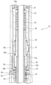
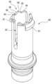
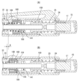
도 3은 회전 구동 기구(22)의 확대 단면도이다. 회전 구동 기구(22)는 후축(40)의 내부 공간에 배치되어 있다. 회전 구동 기구(22)는 중계 부재(21)의 후단부에 접속되어 있다. 전축(12)의 후단면과 회전 구동 기구(22)의 전단면과의 사이에 축 스프링(26)이 배치되어, 회전 구동 기구(22)가 후방으로 가압되어 있다. 축 스프링(26)의 가압력에 의한 회전 구동 기구(22)의 후퇴는, 회전 구동 기구(22)의 후단면이, 후술하는 후축(40)의 규제 돌기부(41)의 전단면(42)에 맞닿는 것에 의해서 규제된다. 심 케이스(23)는 중계 부재(21) 및 회전 구동 기구(22)의 내부를 관통하고, 회전 구동 기구(22)와는 이간(離間)하고 있다. 3 is an enlarged sectional view of the
회전 구동 기구(22)는 원통 모양으로 형성된 회전자(30)와, 원통 모양으로 형성된 제1 캠 형성 부재인 상부 캠 형성 부재(31)와, 원통 모양으로 형성된 제2 캠 형성 부재인 하부 캠 형성 부재(32)와, 원통 모양으로 형성된 실린더 부재(33)와, 원통 모양으로 형성된 토크 캔슬러(canceller)(34)와, 코일 모양의 쿠션 스프링(35)을 가지고 있다. 회전 구동 기구(22)는 이들 부재가 일체로 되어, 유닛화되어 있다. The
또한, 회전 구동 기구(22)의 전방에는, 후술하는 바와 같이, 전환 스위치(50) 및 제1 회전 부재(54)를 가지는 제1 회전 락 기구가 배치되어 있다. Further, in front of the
회전자(30)의 전단부의 내주면에는, 중계 부재(21)의 후단부의 외주면이 감합하고 있다. 회전자(30)의 전단부 근방은, 약간만 지름이 큰 플랜지 모양으로 형성된 부분을 가지며, 해당 부분의 후단면에는 제1 캠면(30a)이 형성되고, 해당 부분의 전단면에는 제2 캠면(30b)이 형성되어 있다. The outer circumferential surface of the rear end of the
상부 캠 형성 부재(31)는, 회전자(30)의 제1 캠면(30a)의 후방에 있어서, 회전자(30)를 회동 가능하게 포위하고 있다. 하부 캠 형성 부재(32)는 상부 캠 형성 부재(31)의 전단부의 외주면에 감합하고 있다. 회전자(30)의 제1 캠면(30a)에 대향하는 상부 캠 형성 부재(31)의 전단면에는, 제1 고정 캠면(31a)이 형성되어 있다. 회전자(30)의 제2 캠면(30b)에 대향하는 하부 캠 형성 부재(32)의 전단부 내면에는, 제2 고정 캠면(32a)이 형성되어 있다. The upper
상부 캠 형성 부재(31)의 후단부의 외주면에는, 원통 모양으로 형성된 실린더 부재(33)가 감합하고 있다. 실린더 부재(33)의 후단부에는, 심 케이스(23)를 삽입 통과시킬 수 있는 삽통공(揷通孔)(33a)이 형성되어 있다. 실린더 부재(33) 내에는, 원통 모양으로 형성되어 전후로 이동 가능한 토크 캔슬러(34)가 배치되어 있다. 토크 캔슬러(34)의 전단부 내면과 실린더 부재(33)의 후단부 내면과의 사이에는, 쿠션 스프링(35)이 배치되어 있다. 쿠션 스프링(35)은, 토크 캔슬러(34)를 매개로 하여, 회전자(30)를 전방으로 가압하고 있다. A
여기서, 중계 부재(21)는 필기 동작에 기초하는 필기심의 후퇴 및 전진 동작(쿠션 동작)을 회전 구동 기구(22), 즉 회전자(30)에 전달함과 아울러, 쿠션 동작에 의해서 생기는 회전 구동 기구(22)에 있어서의 회전자(30)의 회전 운동을, 필기심을 파지한 상태의 척 유닛(20)에 전달한다. 따라서, 척 유닛(20)에 유지된 필기심도 회전한다. Here, the
제1 샤프 펜슬(1)로 필기하고 있을 때 이외에, 즉, 필기심에 필기압이 가해지고 있지 않을 때, 회전자(30)는, 토크 캔슬러(34)를 매개로 한 쿠션 스프링(35)의 가압력에 의해서 전방에 위치하고 있다. 따라서, 회전자(30)의 제2 캠면(30b)은, 제2 고정 캠면(32a)에 맞닿아 서로 맞물린 상태로 된다. 제1 샤프 펜슬(1)로 필기하고 있을 때, 즉, 필기심에 필기압이 가해지고 있을 때, 척 유닛(20)은, 쿠션 스프링(35)의 가압력에 저항하여 후퇴하고, 이것에 수반하여 회전자(30)도 후퇴한다. 따라서, 회전자(30)의 제1 캠면(30a)은, 제1 고정 캠면(31a)에 맞닿아 서로 맞물린 상태로 된다. Except when writing with the first mechanical pencil 1, that is, when writing pressure is not applied to the writing lead, the
도 4는 회전 구동 기구(22)의 회전자(30)의 회전 구동을 설명하는 모식도이며, 도 5는 도 4에 이어지는 회전자(30)의 회전 구동을 설명하는 모식도이다. 도 4 및 도 5에 있어서, 회전자(30)의 상측의 면인 후단면에는, 둘레 방향을 따라서 연속적으로 톱니 모양으로 이루어진 제1 캠면(30a)이 링 모양으로 형성되고, 회전자(30)의 하측의 면인 전단면에는, 마찬가지로 둘레 방향을 따라서 연속적으로 톱니 모양으로 이루어진 제2 캠면(30b)이 링 모양으로 형성되어 있다. FIG. 4 is a schematic view illustrating the rotation drive of the
회전자(30)의 제1 캠면(30a)에 대치하는 상부 캠 형성 부재(31)의 링 모양의 단면(端面)에도 둘레 방향을 따라서 연속적으로 톱니 모양으로 이루어진 제1 고정 캠면(31a)이 형성되고, 회전자(30)의 제2 캠면(30b)에 대치하는 하부 캠 형성 부재(32)의 링 모양의 단면에도 둘레 방향을 따라서 연속적으로 톱니 모양으로 이루어진 제2 고정 캠면(32a)이 형성되어 있다. 회전자(30)에 형성된 제1 캠면(30a) 및 제2 캠면(30b)의 각 캠면과, 상부 캠 형성 부재(31)에 형성된 제1 고정 캠면(31a) 및 하부 캠 형성 부재(32)에 형성된 제2 고정 캠면(32a)의 각 캠면은, 피치가 서로 거의 동일하게 되도록 형성되어 있다. The ring-shaped end surface of the upper
도 4의 (A)는, 필기심에 필기압이 가해지고 있지 않을 때의 상태에 있어서의 회전자(30), 상부 캠 형성 부재(31) 및 하부 캠 형성 부재(32)의 관계를 나타내고 있다. 이 상태에 있어서는, 회전자(30)에 형성된 제2 캠면(30b)은, 쿠션 스프링(35)의 가압력에 의해서, 하부 캠 형성 부재(32)의 제2 고정 캠면(32a)에 대해서 맞닿아 있다. 이때, 회전자(30)의 제1 캠면(30a)과 상부 캠 형성 부재(31)의 제1 고정 캠면(31a)이, 축선 방향에 있어서 캠의 하나의 치(齒)에 대해서 반(半)위상(반피치) 어긋난 관계가 되도록 설정되어 있다. 4(A) shows the relationship between the
도 4의 (B)는, 제1 샤프 펜슬(1)에 의한 필기를 위해서, 필기심에 필기압이 가해진 초기의 상태를 나타내고 있다. 이 상태에 있어서는, 회전자(30)는, 척 유닛(20)의 후퇴에 수반하여 쿠션 스프링(35)을 수축시켜 후퇴한다. 그것에 의해서, 회전자(30)는 상부 캠 형성 부재(31)의 제1 고정 캠면(31a)측으로 이동한다. 4(B) shows an initial state in which writing pressure is applied to the writing lead for writing with the first mechanical pencil 1. As shown in FIG. In this state, the
다음으로, 도 4의 (C)는, 필기심에 필기압이 더 가해져, 회전자(30)가 상부 캠 형성 부재(31)의 제1 고정 캠면(31a)에 맞닿아 후퇴한 상태를 나타내고 있다. 이 상태에 있어서는, 회전자(30)의 제1 캠면(30a)은, 상부 캠 형성 부재(31)의 제1 고정 캠면(31a)에 서로 맞물려 있다. 그것에 의해서, 회전자(30)는 제1 캠면(30a)의 하나의 치의 반위상(반피치)에 상당하는 회전 구동을 받는다. Next, FIG. 4(C) shows a state in which writing pressure is further applied to the writing lead and the
또한, 도 4 및 도 5에 있어서의 회전자(30)의 중앙부에 그린 ○표는, 회전자(30)의 회전 이동량을 나타내고 있다. 그리고 도 4의 (C)에 나타내진 상태에 있어서는, 회전자(30)의 제2 캠면(30b)과 하부 캠 형성 부재(32)의 제2 고정 캠면(32a)이, 축선 방향에 있어서 캠의 하나의 치에 대해서 반위상(반피치) 어긋난 관계가 되도록 설정되어 있다. 4 and 5, the circle drawn at the center of the
다음으로, 도 5의 (D)는, 제1 샤프 펜슬(1)에 의한 필기가 끝나고, 필기심에 대한 필기압이 해제된 초기의 상태를 나타내고 있다. 이 경우에 있어서는, 회전자(30)는 쿠션 스프링(35)의 가압력에 의해서 전진한다. 이것에 의해, 회전자(30)는 하부 캠 형성 부재(32)측으로 이동한다. Next, FIG. 5(D) shows an initial state in which writing with the first mechanical pencil 1 is finished and the writing pressure applied to the writing lead is released. In this case, the
다음으로, 도 5의 (E)는, 회전자(30)가 쿠션 스프링(35)의 가압력에 의해서 하부 캠 형성 부재(32)의 제2 고정 캠면(32a)에 맞닿아 전진한 상태를 나타내고 있다. 이 경우에 있어서는, 회전자(30)의 제2 캠면(30b)은, 하부 캠 형성 부재(32)의 제2 고정 캠면(32a)에 서로 맞물려 있다. 그것에 의해서, 회전자(30)는 제2 캠면(30b)의 하나의 치의 반위상(반피치)에 상당하는 회전 구동을 다시 받는다. Next, FIG. 5(E) shows a state in which the
따라서, 회전자(30)의 중앙부에 그린 ○표로 나타내는 바와 같이, 필기압을 받은 회전자(30)의 축선 방향으로의 왕복 운동, 즉 전후 이동에 수반하여, 회전자(30)는 제1 캠면(30a) 및 제2 캠면(30b)의 하나의 치(1 피치)에 상당하는 회전 구동을 받고, 척 유닛(20)을 매개로 하여, 이것에 파지된 필기심도 마찬가지로 회전 구동된다. 따라서, 필기에 의한 회전자(30)의 축선 방향으로의 1회의 전후 이동에 의해 회전자(30)는 캠의 하나의 치에 대응하는 회전 운동을 받고, 이것을 반복하는 것에 의해서, 필기심은 순차 회전 구동된다. 그럼으로써, 써 나감에 따라서 필기심이 치우쳐 마모되는 것을 방지할 수 있어, 묘선의 굵기나 묘선의 농도가 크게 변화되는 것을 방지할 수 있다. Therefore, as indicated by the circle drawn in the center of the
또한, 쿠션 스프링(35)의 가압력을 받아 회전자(30)를 전방으로 밀어 내는 토크 캔슬러(34)는, 그 전단면과 회전자(30)의 후단면과의 사이에서 미끄러짐을 발생시켜, 회전자(30)의 회전 운동이 쿠션 스프링(35)에 전달되는 것을 방지하고 있다. 즉, 토크 캔슬러(34)에 의해서, 회전자(30)의 회전 운동이 쿠션 스프링(35)에 전달되는 것을 방지하고, 그것에 의해서, 회전자(30)의 회전 동작을 저해하는 쿠션 스프링(35)의 디토션(detorsion)(토크)이 발생하는 것을 방지하고 있다. In addition, the
이상으로부터, 제1 샤프 펜슬(1)은 척 유닛(20)과 회전자(30)를 가지며, 척 유닛(20)의 전후 이동에 의해 필기심의 해제 및 파지를 행함으로써, 필기심을 전방으로 조출할 수 있도록 구성되고, 척 유닛(20)이, 필기심을 파지한 상태에서 중심축선 둘레로 회전 가능하게 되도록 축통(11) 내에 유지되고, 필기심이 받는 필기압에 의한 척 유닛(20)의 후퇴 동작에 수반하여 회전자(30)가 후퇴하여, 회전자(30)를 회전 운동시키는 회전 구동 기구(22)를 구비하고, 회전자(30)의 회전 운동이 척 유닛(20)을 매개로 하여 필기심에 전달되도록 구성되어 있다. From the foregoing, the first mechanical pencil 1 has the
여기서, 사용자가 회전 구동 기구의 온(가동 또는 유효화)과 오프(정지 또는 무효화)를 자유롭게 전환할 수 있도록 하는, 회전 락 기구의 원리에 대해서 설명한다. Here, the principle of the rotary lock mechanism that enables the user to freely switch between on (activation or activation) and off (stopping or invalidation) of the rotation drive mechanism will be described.
회전자(30)는 토크 캔슬러(34)를 매개로 한 쿠션 스프링(35)의 가압력에 의해서 전방으로 가압되어 있다. 따라서, 필기심에 필기압이 가해지고 있지 않은 상태에서는, 도 4의 (A)에 나타내지는 바와 같이, 회전자(30)의 제2 캠면(30b)이 하부 캠 형성 부재(32)의 제2 고정 캠면(32a)에 서로 맞물려 있다. 회전 락 기구는, 필기심에 필기압이 가해지고 있지 않은 상태에 있어서, 도 4의 (C)에 나타내지는 바와 같이, 회전자(30)의 제1 캠면(30a)을 상부 캠 형성 부재(31)의 제1 고정 캠면(31a)에 서로 맞물리도록 구성되어 있다. 그 결과, 필기심에 필기압이 가해졌다고 해도, 회전자(30)가 후퇴하고, 회전하지 않는다. 따라서, 회전 락 기구에 의해서, 회전자(30)의 회전이 락된다. The
이하, 회전 락 기구의 구체적 구성에 대해서 설명한다. Hereinafter, the specific configuration of the rotation lock mechanism will be described.
도 6은 제1 샤프 펜슬(1)의 후축(40)의 종단면도이다. 도 6에 있어서, 상방이 제1 샤프 펜슬(1)에 있어서의 후측이다. 후축(40)의 전측의 측면에는, 상술한 관통공(43)이 마련되어 있다. 후축(40)의 내주면에는, 중심축선 둘레의 둘레 방향을 따라서 경사지게 연장되고 또한 전방을 향해 있는 경사 캠 받이면(44)이 마련되어 있다. 경사 캠 받이면(44)의 후방에는, 축선 방향을 따라서 연장되는 복수의 규제 돌기부(41)가, 둘레 방향을 따라서 등간격으로 마련되어 있다. 규제 돌기부(41)의 전단면(42)은, 회전 구동 기구(22)의 후퇴를 규제하고 있다. 6 is a longitudinal sectional view of the
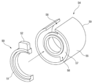
도 7은 전환 스위치(50) 및 제1 회전 부재(54)의 분해 사시도이다. 전환 스위치(50)는 C자 모양의 스위치 지지부(51)와, 스위치부(52)를 가지고 있다. 스위치부(52)는 만곡한 스위치 지지부(51)의 일단의 외면에 있어서, 외방으로 돌출하도록 마련되어 있다. 7 is an exploded perspective view of the
제1 회전 부재(54)는 C자형의 횡단면 형상을 가지는 원통 모양의 캠 본체(55)와, 캠 본체(55)의 전방의 개구(56)을 부분적으로 폐쇄하는 지지판(57)을 가지고 있다. 캠 본체(55)는 C자형의 횡단면 형상을 가지고 있기 때문에, 캠 본체(55)의 측면에는 축선 방향으로 연장되는 간격(58)이 형성되어 있다. 캠 본체(55)의 후단면에는, 경사 캠면(59)이 마련되어 있다. 경사 캠면(59)은 후축(40)의 경사 캠 받이면(44)에 대응하도록 형성되어 있다. The first rotating
축통(11) 내에 있어서, 전환 스위치(50)는 제1 회전 부재(54)의 전방의 개구(56) 내에 삽입되어, 지지판(57)에 맞닿도록 배치된다. 이때, 전환 스위치(50)의 스위치부(52)는, 제1 회전 부재(54)의 간격(58) 내에 삽입된다. 스위치부(52)의 폭은, 간격(58)의 폭과 비교해서 약간만 작게 마련되어 있다. 스위치부(52)는, 도 1에 나타내지는 바와 같이, 후축(40)의 관통공(43)을 거쳐 외부로 돌출되어 있다. 도 1에 있어서, 스위치부(52)는 관통공(43) 내의 좌측에 위치하고 있지만, 다음에 설명하는 바와 같이, 스위치부(52)를 관통공(43) 내의 우측에 위치하도록 슬라이드시킬 수 있다. In
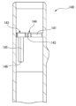
도 8은 제1 회전 락 기구의 동작을 설명하는 종단면도이다. 도 8의 (A)에 나타내진 상태는, 회전 구동 기구(22)가 온인 회전 락 해제 상태이며, 도 8의 (B)에 나타내진 상태는, 회전 구동 기구(22)가 오프인 회전 락 상태이다. 따라서, 도 8의 (A)에 나타내진 회전 구동 기구(22)는, 도 4의 (A)에 나타내진 회전자(30)의 상태에 상당한다. 또한, 도 8의 (A)에 나타내진 상태는, 도 1에 나타내진 스위치부(52)의 상태에 대응한다. 한편, 도 8의 (B)에 나타내진 회전 구동 기구(22)는, 도 4의 (C)에 나타내진 회전자(30)의 상태에 상당하기 때문에, 회전자(30)의 제1 캠면(30a)과 상부 캠 형성 부재(31)의 제1 고정 캠면(31a)은, 서로 맞물려 있다. Fig. 8 is a longitudinal sectional view explaining the operation of the first rotation lock mechanism. The state shown in FIG. 8(A) is a rotation lock release state in which the
도 8의 (A)의 종단면도에서는, 스위치부(52)는 나타내져 있지 않다. 도 8의 (A)의 종단면도에 있어서, 하방에 나타내진 제1 회전 부재(54)의 경사 캠면(59)은 후축(40)의 경사 캠 받이면(44)에 맞닿아 있지만, 상방에 나타내진 제1 회전 부재(54)의 경사 캠면(59)은 후축(40)의 경사 캠 받이면(44)에 맞닿아 있지 않다. 한편, 도 8의 (B)의 종단면도에 있어서, 제1 회전 부재(54)의 경사 캠면(59)은 모두, 후축(40)의 경사 캠 받이면(44)에 맞닿아 있다. 즉, 도 8의 (A)에 나타내진 전환 스위치(50) 및 제1 회전 부재(54)는, 도 8의 (B)에 나타내진 전환 스위치(50) 및 제1 회전 부재(54)보다도 축통(11)에 있어서 후방에 배치되어 있다. In the longitudinal sectional view of Fig. 8 (A), the
도 8의 (A)에 나타내진 상태로부터, 전환 스위치(50)를 조작하는 것에 의해서, 구체적으로는, 도 1에 있어서 스위치부(52)를 둘레 방향을 따라서 손가락으로 슬라이드시켜 관통공(43) 내의 좌에서 우로 이동시키는 것에 의해서, 전환 스위치(50)와 함께 제1 회전 부재(54)를 중심축선 둘레로 회전시킨다. 여기서, 전환 스위치(50) 및 제1 회전 부재(54)는, 축 스프링(26)에 의해서 항상 후방으로 가압되어 있다. 따라서, 제1 회전 부재(54)의 경사 캠면(59)이 후축(40)의 경사 캠 받이면(44)을 따라서 맞닿으면서 슬라이드하고, 슬라이드에 따라서 전환 스위치(50) 및 제1 회전 부재(54)는, 거리 D만큼 후퇴한다. 그 결과, 제1 회전 부재(54), 구체적으로는 지지판(57)의 후단면이 회전자(30)의 전단면을 압압하고, 회전자(30)를 후퇴시킨다. 회전자(30)가 후퇴하는 것에 의해서, 도 4의 (C)에 나타내진 회전자(30)의 상태가 되어, 회전자(30)의 회전이 락된다. By operating the
한편, 도 8의 (B)에 나타내진 상태로부터, 전환 스위치(50)를 조작하는 것에 의해서, 구체적으로는, 도 1에 있어서 스위치부(52)를 둘레 방향을 따라서 손가락으로 슬라이드시켜 관통공(43) 내의 우에서 좌로 이동시키는 것에 의해서, 전환 스위치(50)와 함께 제1 회전 부재(54)를 중심축선 둘레로 역방향으로 회전시킨다. 그것에 의해서, 제1 회전 부재(54)의 경사 캠면(59)이 후축(40)의 경사 캠 받이면(44)을 따라서 맞닿으면서 역방향으로 슬라이드한다. 슬라이드에 따라서 전환 스위치(50) 및 제1 회전 부재(54)는, 축 스프링(26)의 가압력에 저항하여 거리 D만큼 전진하고, 도 8의 (A)에 나타내진 상태가 된다. 전환 스위치(50) 및 제1 회전 부재(54)의 전진에 수반하여, 회전자(30)는 쿠션 스프링(35)의 가압력에 의해서 전진한다. 회전자(30)가 전진하는 것에 의해서, 도 4의 (A)에 나타내진 회전자(30)의 상태가 되어, 회전자(30)의 회전의 락이 해제된다. 또한, 후축(40)의 관통공(43)은, 전환 스위치(50)의 스위치부(52)의 전진 또는 후퇴를 저해하지 않도록, 스위치부(52)의 형상과 비교하여 약간만 크게 형성되어 있다. On the other hand, by operating the
제1 회전 락 기구에 있어서, 전환 스위치(50) 및 제1 회전 부재(54)는, 전환 스위치(50)의 조작에 따라서, 회전 운동을 직진 운동으로 변환하고, 제1 회전 부재(54)에 의한 회전자(30)의 압압 또는 압압의 해제를 가능한 한 임의로 구성할 수 있다. 예를 들어, 전환 스위치(50) 및 제1 회전 부재(54)를 일체적으로 구성해도 된다. 또한, 후축(40)의 경사 캠 받이면(44) 및 제1 회전 부재(54)의 경사 캠면(59)의 형상도, 서로 협동하는 한 임의로 구성할 수 있다. In the first rotational lock mechanism, the
제1 회전 락 기구에서는, 전환 스위치(50)를, 제1 회전 부재(54)가 회전하도록 둘레 방향을 따라서 슬라이드시켰지만, 전환 스위치를 축선 방향을 따라서 슬라이드시키는 것에 의해서, 보다 직접적으로 회전자(30)를 전진 또는 후퇴시키도록 해도 된다. 이 경우, 전환 스위치를, 축통(11) 내에 있어서 회전자(30)를 압압하는 전진 위치와 회전자(30)의 압압을 해제하는 후퇴 위치와의 사이에서 택일적으로 전환할 수 있도록 해도 된다. In the first rotation lock mechanism, the
또한, 이하에 설명하는 다른 회전 락 기구는, 전환 스위치(50) 및 제1 회전 부재(54)를 가지고 있지 않다. 그 때문에, 축 스프링(26)은 회전 구동 기구(22)를 직접적으로 후방으로 가압하고 있다. In addition, other rotation lock mechanisms described below do not have the
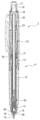
도 9는 제2 샤프 펜슬(2)의 종단면도이고, 도 10은 제2 회전 락 기구의 동작을 설명하는 종단면도이다. 제2 샤프 펜슬(2)은, 제1 샤프 펜슬(1)과 비교하여, 제1 회전 락 기구를 대신하여, 제2 회전 락 기구를 가지고 있다. 그 때문에, 후축(13)의 내면에는 경사 캠 받이면(44) 등은 마련되어 있지 않다. 제2 회전 락 기구는 제2 회전 부재(60) 및 고리 모양 탄성 부재(65)를 가지고 있다. Fig. 9 is a longitudinal sectional view of the second
제2 회전 부재(60)는 입구 부재(14)의 외주면에 감합하고 있다. 제2 회전 부재(60)의 내주면에는, 나선 모양의 캠 홈(61)이 마련되어 있다. 한편, 입구 부재(14)의 외주면에는, 대응하는 나선 모양의 캠 돌기부(14a)가 마련되어 있다. 요컨대, 제2 회전 부재(60)의 캠 홈(61)은 암나사에 상당하고, 입구 부재(14)의 캠 돌기부(14a)는 수나사에 상당한다. 따라서, 입구 부재(14)에 대해서 제2 회전 부재(60)를 중심축선 둘레로 회전시키면, 제2 회전 부재(60)는 회전 방향을 따라서 전진 또는 후퇴한다. 슬라이더(18)의 외주면에는 고리 모양 오목부(18a)가 마련되어 있다. 고리 모양 오목부(18a)에는, 고리 모양 탄성 부재(65)가 감합하고 있다. 고리 모양 탄성 부재(65)는, 예를 들면 O링이다. The second rotating
도 10의 (A)에 나타내진 상태는, 회전 구동 기구(22)가 온인 회전 락 해제 상태이고, 도 10의 (B)에 나타내진 상태는, 회전 구동 기구(22)가 오프인 회전 락 상태이다. 도 10의 (A)에 나타내진 상태에서는, 제2 회전 부재(60)는 전방에 위치하고 있고, 고리 모양 탄성 부재(65)와 간섭하고 있지 않다. The state shown in FIG. 10(A) is the rotation lock release state in which the
이 상태로부터 제2 회전 부재(60)를 회전시키면, 캠 홈(61) 및 캠 돌기부(14a)가 협동하여, 제2 회전 부재(60)가 후퇴한다. 제2 회전 부재(60)의 후퇴에 수반하여, 제2 회전 부재(60)의 내면에 형성된 경사면(62)에 의해서 고리 모양 탄성 부재(65)가 압압되어 후퇴하여, 도 10의 (B)에 나타내진 상태가 된다. 상세하게는, 제2 회전 부재(60)의 후퇴에 의해서, 고리 모양 탄성 부재(65)와 함께, 슬라이더(18), 나아가서는 척 유닛(20) 및 중계 부재(21)가 거리 D만큼 후퇴한다. 중계 부재(21)의 후단부에는 회전자(30)가 감합하고 있기 때문에, 회전자(30)가 후퇴하는 것에 의해서, 도 4의 (C)에 나타내진 회전자(30)의 상태가 되어, 회전자(30)의 회전이 락된다. When the second rotating
한편, 제2 회전 부재(60)를 역방향으로 회전시키면, 캠 홈(61) 및 캠 돌기부(14a)가 협동하여, 제2 회전 부재(60)가 전진한다. 제2 회전 부재(60)의 전진에 수반하여, 제2 회전 부재(60)의 경사면(62)에 의한 고리 모양 탄성 부재(65)의 압압이 해제되어, 도 10의 (A)에 나타내진 상태가 된다. 그 결과, 회전자(30)가 전진하는 것에 의해서, 도 4의 (A)에 나타내진 회전자(30)의 상태가 되어, 회전자(30)의 회전의 락이 해제된다. On the other hand, when the second rotating
제2 회전 락 기구에 있어서, 제2 회전 부재(60) 및 고리 모양 탄성 부재(65)는, 회전 운동을 직진 운동으로 변환하고, 중계 부재(21)를 매개로 하여 회전자(30)의 압압 또는 압압의 해제를 가능한 한 임의로 구성할 수 있다. 예를 들어, 고리 모양 탄성 부재(65) 및 슬라이더(18)를 일체적으로 구성해도 된다. 또한, 제2 회전 락 기구에서는, 제2 회전 부재(60)를 회전시켜 조작했지만, 입구 부재(14)에 감합시킨 감합 부재를 축선 방향을 따라서 슬라이드시키는 것에 의해서, 보다 직접적으로 고리 모양 탄성 부재(65), 나아가서는 회전자(30)를 전진 또는 후퇴시키도록 해도 된다. 이 경우, 감합 부재를, 입구 부재(14)의 외면에 있어서 회전자(30)를 압압하는 전진 위치와 회전자(30)의 압압을 해제하는 후퇴 위치와의 사이에서 택일적으로 전환할 수 있도록 해도 된다. In the second rotational lock mechanism, the second rotational member (60) and the annular elastic member (65) convert rotational motion into linear motion, and the rotor (30) is pressed via the relay member (21). Alternatively, release of the pressure can be configured arbitrarily as much as possible. For example, the annular
도 11은 제3 샤프 펜슬(3)의 종단면도이다. 제3 샤프 펜슬(3)은, 제1 샤프 펜슬(1)과 비교하여, 제1 회전 락 기구를 대신하여, 제3 회전 락 기구를 가지고 있다. 제3 회전 락 기구는 노크 부재(80), 노크 회전자(90) 및 가압 스프링(99)을 가지고 있고, 노크식의 필기구의 출몰 기구 또는 노크 기구를 이용하고 있다. 따라서, 후술하는 출몰 기구 이외의 다른 출몰 기구를 적용하여, 제3 회전 락 기구를 구성해도 된다. Fig. 11 is a longitudinal sectional view of the third
도 12는 제3 샤프 펜슬(3)의 후축(70)의 후단부의 종단면도이다. 도 12에 있어서, 상방이 제3 샤프 펜슬(3)에 있어서의 전측이다. 후축(70)의 내주면에는, 축선 방향으로 연재하고 또한 후단부에 있어서 서로 연결하는 4개의 제1 돌기부(71) 및 4개의 제2 돌기부(72)를 가진다. 제1 돌기부(71) 및 제2 돌기부(72)는, 둘레 방향을 따라서 등간격이면서 교호로 배치되어 있다. 12 is a longitudinal sectional view of the rear end of the
제1 돌기부(71) 각각의 상면, 즉 후축(70)의 중심축선에 대향하는 면에는, 전후 방향에 대해서 수직인 평면에 대해서 둘레 방향으로 경사지고 또한 전방을 향해 있는 캠면(73)이 마련되어 있다. 따라서, 제1 돌기부(71)에 있어서, 캠면(73)의 후방은 보다 두꺼운, 즉 보다 높은 돌기이다. 한편, 제1 돌기부(71)에 있어서, 캠면(73)의 전방은 보다 얇은, 즉 보다 낮은 돌기이며, 제2 돌기부(72)와 동일한 높이의 돌기이다. 제1 돌기부(71) 및 제2 돌기부(72)의 전단면(74)은, 회전 구동 기구(22)의 후퇴를 규제하고 있다. 제1 돌기부(71) 및 제2 돌기부(72) 각각은, 전후 방향을 따라서 연장되는 규제면인 세로벽면(75)을 가지고 있다. 제1 돌기부(71) 및 제2 돌기부(72) 각각을 연결하는 부분의 전단면에는, 맞닿음면(76)이 형성되어 있다. 캠면(73) 및 세로벽면(75)은, 외부 캠(77)을 구성한다. On the upper surface of each of the
도 13은 제3 샤프 펜슬(3)의 노크 부재(80)의 사시도이다. 도 13에 있어서, 상방이 제3 샤프 펜슬(3)에 있어서의 전측이다. 노크 부재(80)는 양단이 개구된 통 모양의 부재이다. 노크 부재(80)의 전측의 외주면에는, 2개의 돌기부(81)가 대칭 위치에 마련되어 있다. 또한, 2개의 돌기부(81) 사이에는, 노크 부재(24)의 전단면으로부터 후방을 향하여 연장되는 슬릿부(82)가 마련되어 있다. 돌기부(81) 각각은, 노크 조작에 의해서, 제1 돌기부(71) 사이를 전후로 이동하도록 구성되어 있다. 즉, 2개의 돌기부(81)의 외면을 포함하도록 하는 외접원의 지름은, 후축(70)의 제1 돌기부(71)의 상면에 접하는 내접원의 지름보다도 크고, 후축(70)의 제2 돌기부(72)의 상면에 접하는 내접원의 지름보다도 작게 설정되어 있다. 노크 부재(80)의 전단면에는 캠면(83)이 형성되어 있다. 캠면(83)은 대칭적으로 형성된 산부(山部)(84) 및 골부(85)를 가진다. 8개의 산부(84) 및 골부(85)는, 경사면(86)에 의해서 접속되어 있다. 13 is a perspective view of the
도 14는 제3 샤프 펜슬(3)의 노크 회전자(90)의 사시도이다. 도 14에 있어서, 상방이 제3 샤프 펜슬(3)에 있어서의 전측이다. 노크 회전자(90)는 양단이 개구된 통 모양의 부재이다. 노크 회전자(90)는 대경부(大徑部)(90a)와, 대경부(90a)의 후방에 형성되고 또한 노크 부재(80) 내에 삽입되어 심(芯)맞춤에 사용되는 소경부(小徑部)(90b)를 가지고 있다. 대경부(90a)는 소경부(90b)보다도 큰 지름을 가진다. 대경부(90a)의 외주면에는, 둘레 방향을 따라서 등간격으로 배치되고 또한 전후 방향을 따라서 연장되는 4개의 세로홈(91)이 형성되어 있다. 세로홈(91)의 깊이는, 대경부(90a)와 소경부(90b)와의 반경의 차이보다는 얕다. 대경부(90a)에는, 4개의 세로홈(91)에 의해서 형성된 4개의 돌기부(92a)로 이루어지는 내부 캠(92)이 형성되어 있다. 대경부(90a)의 후단면에 있어서, 내부 캠(92)보다도 지름 방향 내측에는, 전체 둘레에 걸쳐, 노크 부재(80)의 캠면(83)과 상보적으로 형성되어 협동하는 캠 받이면(93)이 형성되어 있다. 즉, 대경부(90a)에는, 내부 캠(92) 및 캠 받이면(93)이 일체적으로 마련되어 있다. 14 is a perspective view of the
캠 받이면(93)은 톱날 모양으로 형성되어 있고, 전후 방향에 대해서 수직인 평면에 대해서 둘레 방향으로 경사진 경사면(94)을 가진다. 8개의 경사면(94)에 있어서 1개씩 걸러 있는 경사면(94a)은, 상술한 세로홈(91)에 의해서 절결되어 있다. 인접하는 세로홈(91)과의 사이의 인접하는 경사면(94)은, 전후 방향을 따라서 연장되는 세로벽면(95)에 의해서 접속되어 있다. 즉, 캠 받이면(93)은 4개의 세로벽면(95)을 가진다. 노크 부재(80)의 캠면(83)과 노크 회전자(90)의 캠 받이면(93)은 상보적으로 형성되어 있기 때문에, 세로홈(91)의 부분, 및 경사면(94)과 세로벽면(95)에 의해서 형성된 예각의 부분에는, 경사면(94)과는 역방향으로 경사진 경사면(94b)이 마련되어 있다. 경사면(94b)은 노크 부재(80)의 캠면(83)과 협동하는데 충분한 높이, 즉 지름 방향의 길이로 마련되어 있다. The
요컨대, 대경부(90a)의 지름 방향 내측에는, 노크 부재(80)의 캠면(83)과 협동하는 캠 받이면(93)이 마련되고, 대경부(90a)의 지름 방향 외측에는, 후축(70)의 외부 캠(77)과 협동하는 내부 캠(92)이 마련되어 있다. 또한, 노크 회전자(90)에는, 중심축선을 따라서 관통공(96)이 마련되어 있고, 관통공(96)에는, 심 케이스(23)가 삽입된다. In short, a
내부 캠(92)은, 노크 조작에 의해서 노크 회전자(90)가 중심축선 둘레로 회전하면, 외부 캠(77)과 맞물리거나 또는 맞물림 해제된다. 즉, 내부 캠(92)의 돌기부(92a)는, 노크 조작에 의해서 노크 회전자(90)가 중심축선 둘레로 회전하면, 외부 캠(77)의 제1 돌기부(71)와 맞물리거나 또는 외부 캠(77)의 제1 돌기부(71) 사이에 배치된다. 내부 캠(92)의 돌기부(92a)가 외부 캠(77)의 제1 돌기부(71) 사이에 배치될 때, 외부 캠(77)의 제1 돌기부(71)는 내부 캠(92)의 돌기부(92a) 사이, 즉 세로홈(91) 내에 배치된다. The
노크 부재(80)의 캠면(83) 및 노크 회전자(90)의 캠 받이면(93)은, 내부 캠(92)이 외부 캠(77)과 맞물리거나 또는 맞물림 해제될 때, 노크 부재(80)의 캠면(83)의 산부(84)가, 둘레 방향에 있어서, 내부 캠(92)의 캠 받이면(93)의 경사면(94) 상에 위치하도록 구성되어 있다. 즉, 캠면(83)의 경사면(86)과 캠 받이면(93)의 경사면(94)은, 위상이 어긋나게 배치된다. 이 때문에, 노크 조작에 의해서 캠면(83)의 경사면(86)이 캠 받이면(93)의 경사면(94)을 압압하면, 이 조작 하중 및 가압 스프링(99)에 의한 가압력에 기인하여, 노크 회전자(90)는 둘레 방향의 분력(分力)을 받아 중심축선 둘레로 회전한다. 한편, 노크 부재(80)는 돌기부(81)가 외부 캠(77)의 세로벽면(75)에 둘레 방향으로 맞닿는 것에 의해서 중심축선 둘레의 회전이 규제되어 있다. 이러한 동작에 대해서, 도 15를 참조하면서 설명한다. The cam face 83 of the
도 15는 제3 회전 락 기구의 동작, 즉 출몰 기구의 동작을 설명하는 모식도이며, 제3 샤프 펜슬(3)의 각 캠의 관계를 나타내는 모식도이다. 즉, 도 15는 후축(70)의 외부 캠(77)과 노크 부재(80)와 노크 회전자(90)의 위치 관계를 나타내는 모식도이다. 보다 상세하게는, 외부 캠(77)을 둘레 방향으로 전개한 것에 대해서, 노크 부재(80)의 캠면(83) 및 노크 회전자(90)의 캠 받이면(93)의 위치를 나타낸 것이다. 도면 중, 상방이 제3 샤프 펜슬(3)의 전측이며, 하방이 제3 샤프 펜슬(3)의 후측이다. 또한, 도 16은 제3 회전 락 기구의 동작을 설명하는 종단면도이다. FIG. 15 is a schematic diagram explaining the operation of the third rotational lock mechanism, that is, the operation of the retracting mechanism, and is a schematic diagram showing the relationship between the respective cams of the third
제3 회전 락 기구의 동작은, 노크식의 필기구의 출몰 기구와 마찬가지로, 노크 부재(80) 또는 노크 커버(15)를 전방으로 압압하는 노크 조작을 하는 것에 의해서 행해진다. 그리고, 노크식의 필기구에 있어서의 필기 상태, 즉 노크 회전자(90)가 전방에 위치하는 회전 락 상태인, 도 16의 (B)에 나타내진 상태에서, 회전 구동 기구가 오프로 된다. 한편, 노크식의 필기구에 있어서의 비필기 상태, 즉 노크 회전자(90)가 후방에 위치하는 상태인, 도 16의 (A)에 나타내진 회전 락 해제 상태에서, 회전 구동 기구가 온으로 된다. 노크 회전자(90)는 노크 부재(80)의 캠면(83)과 노크 회전자(90)의 캠 받이면(93)의 캠 기구에 의해서 회전력이 주어지고, 노크 조작마다 도 15에 있어서 좌에서 우로 이동한다. The operation of the third rotational lock mechanism is performed by carrying out a knocking operation to press the
도 15의 (A)에 나타내진 상태는, 도 16의 (A)와 동일한 상태이다. 도 15의 (A)에 나타내진 상태에서는, 내부 캠(92)은 외부 캠(77)과 맞물려 있지 않다. 즉, 내부 캠(92)의 돌기부(92a)가 외부 캠(77)의 제1 돌기부(71) 사이에 배치되고, 외부 캠(77)의 제1 돌기부(71)는 내부 캠(92)의 돌기부(92a) 사이, 즉 세로홈(91) 내에 배치되어 있다. 캠면(83) 및 캠 받이면(93)은, 위상이 어긋나게 배치되어 있다. The state shown in FIG. 15(A) is the same state as that of FIG. 16(A). In the state shown in FIG. 15(A), the
이 상태로부터, 가압 스프링(99)의 가압력에 저항하여 노크 부재(80)를 압압하여, 노크 부재(80) 및 노크 회전자(90)를 전진시키면, 도 15의 (B)에 나타내지는 바와 같이, 내부 캠(92)의 캠 받이면(93)의 세로홈(91)의 후단부가, 전후 방향에 있어서 외부 캠(77)의 제1 돌기부(71)의 전단부를 넘는다. 이때, 노크 회전자(90)의 캠 받이면(93)의 경사면(94)과 외부 캠(77)의 캠면(73)이 일치하고, 외부 캠(77)의 제1 돌기부(71)의 세로벽면(75)에 의한, 노크 회전자(90)의 중심축선 둘레의 회전의 규제는, 해제된다. From this state, when the
도 15의 (B)에 나타내진 상태로부터 노크 부재(80)의 압압을 해제하면, 노크 부재(80) 및 노크 회전자(90)는, 가압 스프링(99)의 가압력에 의해서 후퇴한다. 이때, 노크 회전자(90)의 중심축선 둘레의 회전은, 외부 캠(77)의 제1 돌기부(71)의 세로벽면(75)에 의해서 규제되어 있지 않다. 그 때문에, 가압 스프링(99)의 가압력에 의해서, 노크 회전자(90)의 캠 받이면(93)의 경사면(94)이 외부 캠(77)의 캠면(73) 또는 노크 부재(80)의 캠면(83)의 경사면(86)을 압압하면, 노크 회전자(90)는 둘레 방향의 분력을 받아 중심축선 둘레로 회전한다. When the pressing of the
노크 회전자(90)의 후퇴 및 회전은, 내부 캠(92)은 외부 캠(77)과 맞물리는 것에 의해서 규제된다. 즉, 내부 캠(92)의 캠 받이면(93)의 경사면(94) 및 세로벽면(95)이, 외부 캠(77)의 제1 돌기부(71)의 캠면(73) 및 세로벽면(75)과 맞물리는 것에 의해서, 노크 회전자(90)의 후퇴 및 회전이 규제되어, 도 15의 (C)에 나타내진 상태가 된다. The retraction and rotation of the
도 15의 (C)에 나타내진 상태는, 도 16의 (B)와 동일한 상태이다. 이 상태로부터, 가압 스프링(99)의 가압력에 저항하여 노크 부재(80)를 압압하여, 노크 부재(80) 및 노크 회전자(90)를 전진시키면, 도 15의 (D)에 나타내지는 바와 같이, 내부 캠(92)의 캠 받이면(93)의 세로벽면(95)의 후단부가, 전후 방향에 있어서 외부 캠(77)의 제1 돌기부(71)의 전단부를 넘는다. 이때, 노크 회전자(90)의 캠 받이면(93)의 경사면(94)과 외부 캠(77)의 캠면(73)이 일치하고, 외부 캠(77)의 제1 돌기부(71)의 세로벽면(75)에 의한, 노크 회전자(90)의 중심축선 둘레의 회전의 규제는, 해제된다. The state shown in FIG. 15(C) is the same state as that of FIG. 16(B). From this state, when the
도 15의 (D)에 나타내진 상태로부터 노크 부재(80)의 압압을 해제하면, 노크 부재(80) 및 노크 회전자(90)는, 가압 스프링(99)의 가압력에 의해서 후퇴한다. 이때, 노크 회전자(90)의 중심축선 둘레의 회전은, 외부 캠(77)의 제1 돌기부(71)의 세로벽면(75)에 의해서 규제되어 있지 않다. 그 때문에, 가압 스프링(99)의 가압력에 의해서, 노크 회전자(90)의 캠 받이면(93)의 경사면(94)이 외부 캠(77)의 캠면(73) 또는 노크 부재(80)의 캠면(83)의 경사면(86)을 압압하면, 노크 회전자(90)는 둘레 방향의 분력을 받아 중심축선 둘레로 회전한다. When the pressing of the
노크 회전자(90)는 회전하면서 후퇴하기 때문에, 도 15의 (E)에 나타내지는 바와 같이, 내부 캠(92)의 돌기부(92a)가 외부 캠(77)의 제1 돌기부(71) 사이에 배치되고, 외부 캠(77)의 제1 돌기부(71)는 내부 캠(92)의 돌기부(92a) 사이, 즉 세로홈(91) 내에 배치된다. 그 결과, 외부 캠(77)과 내부 캠(92)과의 맞물림은 해제된다. 돌기부(81)가 외부 캠(77)의 세로벽면(75)에 둘레 방향으로 맞닿는 것에 의해서, 노크 부재(80)의 중심축선 둘레의 회전은, 항상 규제되어 있다. 도 15의 (E)에 나타내진 상태로부터, 노크 부재(80) 및 노크 회전자(90)는 그대로 후퇴하여, 다시 도 15의 (A)에 나타내진 상태가 된다. Since the
도 16의 (B)에 나타내진 회전 락 상태에서는, 노크 회전자(90)가 전진하는 것에 의해서, 가압 스프링(99)이 보다 압축된다. 가압 스프링(99)의 일단은 노크 회전자(90)에 맞닿고, 가압 스프링(99)의 타단은 회전 구동 기구(22)의 후단면에 맞닿아 있다. 따라서, 회전 구동 기구(22)는 가압 스프링(99)의 압축에 의해서 증가한 전방을 향하는 가압력과, 축 스프링(26)의 후방을 향하는 가압력의 밸런스에 의해서, 도 16의 (A)에 나타내진 상태와 비교하여 거리 D만큼 전진하고 있다. In the rotation locked state shown in FIG. 16(B), the
회전 구동 기구(22)가 전진하면, 축통(11) 내의 각 부재 사이에 존재하고 있던 미소한 클리어런스, 예를 들면, 입구 부재(14), 척 유닛(20)이나 중계 부재(21) 등의 사이에 존재하고 있던 클리어런스가 없어진다. 그 결과, 회전자(30)가 회전 구동 기구(22)에 있어서 상대적으로 후퇴한 상태가 되어, 도 4의 (C)에 나타내진 회전자(30)의 상태가 되기 때문에, 회전자(30)의 회전이 락된다. When the
제3 샤프 펜슬(3)에서는, 사용자는 회전 구동 기구(22)를 온 또는 오프로 하는 회전 락 노크 조작과, 필기심을 조출하는 조출 노크 조작의 2개의 노크 조작을 행할 수 있다. 즉, 회전 구동 기구(22)를 온 또는 오프로 하고 싶은 경우에는, 도 15를 참조하면서 설명한 바와 같이, 내부 캠(92)이, 전후 방향에 있어서 외부 캠(77)을 넘을 때까지 노크 부재(80), 나아가서는 노크 회전자(90)를 전진시킨다. 한편, 필기심을 조출하기 위한 노크 조작은, 척 유닛(20)이 작동할 정도로 노크 부재(80), 나아가서는 척 유닛(20)을 전진시킨다. 즉, 회전 락 노크 조작은 조출 노크 조작보다도 깊게 노크할 필요가 있다. 또한, 회전 락 노크 조작에 있어서도 필기심의 조출은 행해진다. In the third
도 17은 제4 회전 락 기구의 동작을 설명하는 종단면도이다. 제4 회전 락 기구는, 제3 회전 락 기구의 구성에 더하여, 스페이서(100)를 가지고 있다. 스페이서(100)는 회전자(30)의 전방에 배치되어 있다. 구체적으로는, 전축(12)의 후단부에 있어서 중계 부재(21)의 외주면에 감합하도록 배치되어 있다. 노크 조작에 의해서, 노크 회전자(90), 나아가서는 회전 구동 기구(22)가 전진할 때, 회전자(30)의 전단면이 스페이서(100)의 후단면에 맞닿아, 회전자(30)의 전진이 규제된다. 그 결과, 도 4의 (C)에 나타내진 회전자(30)의 상태가 되어, 회전자(30)의 회전이 락된다. Fig. 17 is a longitudinal sectional view explaining the operation of the fourth rotational lock mechanism. The fourth rotation lock mechanism has a
제4 회전 락 기구가, 제3 회전 락 기구에 더하여 스페이서(100)를 가지고 있는 것에 의해서, 스페이서(100)가 직접적으로 회전자(30)를 압압하기 때문에, 보다 확실하게 회전자(30)의 회전을 락할 수 있다. Since the
그런데, 축통의 일부, 즉 전축 또는 후축을, 중심축선 둘레로 회전시키는 것에 의해서 리필이 출몰하는 회전 조출 기구를 구비한 필기구가 일반적으로 알려져 있다. 다음으로, 신규한 회전 조출 기구를 이용한 회전 락 기구에 대해서 설명한다. 그 전에 우선은, 이 신규한 회전 조출 기구를 구비한 볼펜을 이용하여, 그 구성을 설명한다. [0003] By the way, a writing instrument equipped with a rotary drawing mechanism in which a refill emerges and retracts by rotating a part of the barrel, that is, a front shaft or a rear shaft around a central axis, is generally known. Next, a rotation lock mechanism using a novel rotation drawing mechanism will be described. Before that, first, the configuration will be described using a ballpoint pen equipped with this novel rotary drawing mechanism.
도 18은 제1 볼펜(5)의 비필기 상태에 있어서의 종단면도이다. 제1 볼펜(5)은 통 모양으로 형성된 축통(11)을 가지고 있다. 축통(11)은 전축(12)과, 전축(12)의 후단부에 감합(嵌合) 또는 나사 결합하는 후축(110)과, 후축(110)의 후단부에 마련된 통 모양으로 형성된 제3 회전 부재(120)를 가지고 있다. 또한, 제1 볼펜(5)은 축통(11) 내에 배치되고 또한 일단에 필기부(6)를 구비한 필기체(筆記體)인 리필(7)과, 코일 스프링(8)과, 스프링 지지 부재(9)와, 제1 접동 부재(130)를 가지고 있다. Fig. 18 is a longitudinal sectional view of the
제1 볼펜(5)의 축선 방향에 있어서, 필기부(6)측을 「전」측으로 규정하고, 필기부(6)와는 반대측을 「후」측으로 규정한다. 제1 볼펜(5)에서는, 제1 회전 조출 기구의 조작에 의해서, 리필(7)이 축통(11) 내를 전후로 이동한다. 이때, 필기부(6)가 축통(11)으로부터 돌출된 상태를 필기 상태(도 23)라고 칭하고, 필기부(6)가 축통(11) 내에 몰입(沒入)한 상태를 비필기 상태(도 18 및 도 22)라고 칭한다. In the axial direction of the
도 19는 제1 볼펜(5)의 후축(110)의 후단부의 종단면도이다. 도 19에 있어서, 상방이 제1 볼펜(5)에 있어서의 후측이다. 후축(110)의 후부의 내주면에는, 둘레 방향을 따라서 고리 모양 돌기부(111)가 마련되어 있다. 후술하는 도 24에 나타내지는 바와 같이, 고리 모양 돌기부(111)는 전체 둘레에 걸쳐 마련되어 있지 않다. 예를 들어, 후축(110)의 내주면에 있어서, 둘레 방향에 따른 일부분, 예를 들면 전체 둘레 중 1/4의 부분에는, 고리 모양 돌기부(111)를 대신하여, 오목부(112)가 형성된다. 오목부(112)에는, 고리 모양 돌기부(111)의 양방의 단부로부터 약간 이간하여, 2개의 소(小)돌기부(113)가 각각 마련되어 있다. 그 결과, 고리 모양 돌기부(111)와 소돌기부(113)와의 사이에는, 2개의 걸림 오목부(114)가 형성된다. 둘레 방향에 있어서의 고리 모양 돌기부(111)의 중앙에는, 키 돌기부(115)가 마련되고, 대향하는 둘레 방향에 있어서의 오목부(112)의 중앙에는, 마찬가지의 키 돌기부(115)가 마련되어 있다. 2개의 키 돌기부(115)는, 축선 방향에 있어서, 고리 모양 돌기부(111)와 인접하여 마련되어 있다. 19 is a longitudinal sectional view of the rear end of the
도 20은 제1 볼펜(5)의 제3 회전 부재(120)의 사시도이다. 도 20에 있어서, 상방이 제1 볼펜(5)에 있어서의 후측이다. 제3 회전 부재(120)는 후축(110)에 대해서 중심축선 둘레로 회전 가능하게 장착된다. 제3 회전 부재(120)는 회전시킬 때에 사용자가 파지하는 통 모양의 파지부(121)를 가지고 있다. 파지부(121)의 외주면에는, 클립(121a)이 마련되어 있다. 파지부(121)의 전방에는, 보다 소경으로 형성되고 또한 후축(110) 내에 삽입되는 삽입부(122)가 마련되어 있다. 삽입부(122)에는, 전단면으로부터 후방을 향하여 대략 직사각형이면서 대향하는 2개의 절결부(123)가 마련되어 있다. 2개의 절결부(123)에 의해서, 전방을 향하여 연장되는 2개의 캠 암(124)이 형성되어 있다. 2개의 캠 암(124)의 전단면에는, 둘레 방향을 따라서 동일 방향으로 경사진 캠면(125)이 마련되어 있다. 일방의 절결부에 있어서의 삽입부(122)의 전단면의 중앙 부분에는, 전방을 향하여 연장되는 직사각형 돌기부(126)가 형성되어 있다. 직사각형 돌기부(126)의 외면에는, 걸림 돌기부(127)이 마련되어 있다. 2개의 캠 암(124) 각각의 외면에는, 축선 방향에 있어서 걸림 돌기부(127)와 동일한 위치에, 둘레 방향을 따라서 접동 홈(128)이 마련되어 있다. 20 is a perspective view of the third
도 21은 제1 볼펜(5)의 제1 접동 부재(130)의 사시도이다. 도 21에 있어서, 상방이 제1 볼펜(5)에 있어서의 후측이다. 제1 접동 부재(130)는 접동 본체부(131)를 가지고 있다. 접동 본체부(131)는 후단부가 폐쇄된 통 모양의 부재이다. 접동 본체부(131)의 외주면에는, 2개의 캠 돌기부(132)가 마련되어 있다. 2개의 캠 돌기부(132)는, 축선 방향을 따라서 연장되는 2개의 키 홈(133)에 의해서 각각 이간하고 있다. 2개의 캠 돌기부(132)의 후단면에는, 제3 회전 부재(120)의 캠면(125)에 대응하여 마찬가지로 경사진 캠 받이면(134)이 마련되어 있다. 캠 받이면(134) 각각에 있어서, 가장 전방에 위치하는 부분을 시단부(始端部)(134a)로 하고, 가장 후방에 위치하는 부분을 종단부(終端部)(134b)로 정의한다. 21 is a perspective view of the first sliding
축통(11) 내에 있어서, 제3 회전 부재(120)는, 후축(110)의 후방으로부터 내부로 삽입된다. 이때, 2개의 캠 암(124)이 지름 방향 내측으로 휘고, 접동 홈(128) 내에 후축(110)의 고리 모양 돌기부(111)가 배치된다. 제3 회전 부재(120)를 후축(110)에 대해서 중심축선 둘레로 회전시킬 때, 접동 홈(128)이 레일의 역할을 하여, 접동 홈(128) 내에서 고리 모양 돌기부(111)를 상대적으로 이동시킬 수 있다. 또한, 후축(110)의 고리 모양 돌기부(111)가 제3 회전 부재(120)의 접동 홈(128) 내에 배치되는 것에 의해서, 제3 회전 부재(120)가 후축(110)으로부터 떨어지기 어렵게 된다. 제3 회전 부재(120)의 걸림 돌기부(127)는, 오목부(112) 내에 배치된다. In the
제1 접동 부재(130)는 후축(110)의 전방으로부터 내부로 삽입되고, 접동 본체부(131)의 후단부가 제3 회전 부재(120)의 전방으로부터 내부로 삽입된다. 제1 접동 부재(130)의 삽입시에는, 후축(110)의 키 돌기부(115)가 제1 접동 부재(130)의 키 홈(133) 내에 배치되도록, 제3 회전 부재(120)의 캠 암(124)이 제1 접동 부재(130)의 캠 받이면(134)에 의해서 안내된다. 키 돌기부(115)가 키 홈(133) 내에 배치되는 것에 의해서, 제1 접동 부재(130)는 중심축선 둘레로 회전하지 않고, 축통(11) 내를 전후로 이동시킬 수 있다. 제1 접동 부재(130)의 접동 본체부(131)가 제3 회전 부재(120)의 내부에 삽입되는 것에 의해서, 2개의 캠 암(124)은 지름 방향 내측으로 휠 수 없게 된다. 그 결과, 제3 회전 부재(120)가 후축(110)으로부터 탈락하는 것을 방지할 수 있다. The first sliding
제1 접동 부재(130)는 코일 스프링(8)에 의해서 후방으로 가압되어 있다. 코일 스프링(8)의 일단은, 제1 접동 부재(130)의 캠 돌기부(132)의 전단면에 맞닿고, 코일 스프링(8)의 타단은, 스프링 지지 부재(9)에 의해서 지지된다. 스프링 지지 부재(9)는, 전축(12)의 후단면에 의해서, 전진이 규제되어 있다. 리필(7)은 코일 스프링(8) 및 스프링 지지 부재(9)를 관통하고 있다. 리필(7)의 후단부가 접동 본체부(131)의 전방의 개구로부터 내부에 삽입되어 감합하는 것에 의해서, 리필(7)은 제1 접동 부재(130)에 대해서 일체적으로 장착되어 있다(도 18). The first sliding
도 22는 제1 볼펜(5)의 비필기 상태에 있어서의 사시도이고, 도 23은 제1 볼펜(5)의 필기 상태에 있어서의 사시도이다. 도 22 및 도 23에 있어서, 후축(110)은 생략되어 있다. 22 is a perspective view of the
도 22에 나타내진 비필기 상태에서는, 코일 스프링(8)에 의한 제1 접동 부재(130)의 후퇴는, 후술하는 바와 같이, 제3 회전 부재(120)의 캠 암(124)이, 후축(110)의 키 돌기부(115)에 대해서 둘레 방향으로 맞닿아 제3 회전 부재(120)의 회전이 규제된 상태에서, 캠 암(124)이 캠 돌기부(132)와 걸리는 것에 의해서 규제된다. 이때, 제3 회전 부재(120)의 캠면(125)은, 제1 접동 부재(130)의 캠 받이면(134)에 있어서 시단부(134a)에 배치되어 있다. In the non-writing state shown in FIG. 22, retraction of the first sliding
이 상태로부터, 파지부(121)를 파지하여 제3 회전 부재(120)를 회전시키면, 제3 회전 부재(120)의 캠면(125) 및 제1 접동 부재(130)의 캠 받이면(134)이 협동하는 것에 의해서, 제3 회전 부재(120)에 가해지는 회전 방향의 힘이, 제1 접동 부재(130)를 전진시키는 힘으로 변환된다. 즉, 캠면(125) 및 캠 받이면(134)에 있어서, 서로 동일 방향으로 경사진 경사면으로부터 축 방향의 분력을 받아, 코일 스프링(8)의 가압력에 저항하여 제1 접동 부재(130)는 전진한다. 제3 회전 부재(120)의 캠면(125)이, 제1 접동 부재(130)의 캠 받이면(134)에 있어서 종단부(134b)까지 이동하면, 제1 접동 부재(130)의 전진은 정지하여, 제1 볼펜(5)은 필기 상태가 된다(도 23). From this state, when the third
한편, 도 23에 나타내진 필기 상태에서는, 제3 회전 부재(120)를 역방향으로 회전시키는 것에 의해서, 코일 스프링(8)의 가압력을 받아 제1 접동 부재(130)가 후퇴한다. 제3 회전 부재(120)의 캠면(125)이, 제1 접동 부재(130)의 캠 받이면(134)에 있어서 시단부(134a)까지 이동하면, 제1 접동 부재(130)의 후퇴는 정지하여, 제1 볼펜(5)은 비필기 상태가 된다(도 22). On the other hand, in the writing state shown in FIG. 23, by rotating the third
도 24는 제1 회전 조출 기구의 동작을 설명하는 횡단면도이다. 구체적으로는, 도 24는, 제1 볼펜(5)에 있어서, 제3 회전 부재(120)의 걸림 돌기부(127)를 포함하는 횡단면이다. 도 24의 (A)는, 제3 회전 부재(120)가 일방으로 회전된, 도 22에 상당하는 비필기 상태의 제1 볼펜(5)을 나타내고 있다. 한편, 도 24의 (B)는, 제3 회전 부재(120)가 타방으로 회전된, 도 23에 상당하는 필기 상태의 제1 볼펜(5)을 나타내고 있다. Fig. 24 is a cross-sectional view illustrating the operation of the first rotary drawing mechanism. Specifically, FIG. 24 is a cross section including the locking
도 24의 (A)에 나타내지는 바와 같이, 캠 암(124)의 일방은, 키 돌기부(115)의 일방에 대해서 둘레 방향에 있어서 맞닿아 있다. 이것에 대해, 도 24의 (B)에 나타내지는 바와 같이, 캠 암(124)의 상기 일방은, 키 돌기부(115)의 타방에 대해서 둘레 방향에 있어서 맞닿아 있다. 각각의 경우, 즉 캠 암(124)이 키 돌기부(115)에 맞닿아 있는 경우, 제3 회전 부재(120)의 걸림 돌기부(127)가, 후축(110)의 걸림 오목부(114) 내에 감합하고 있다. 요컨대, 걸림 돌기부(127)는 제3 회전 부재(120)의 회전에 따라서 소돌기부(113)를 타고 넘어, 캠 암(124)이 키 돌기부(115)에 맞닿는 것과 동시에, 걸림 오목부(114) 내에 감합한다. 그 결과, 제3 회전 부재(120)를 일시적으로 고정할 수 있어, 의도하지 않게 필기 상태 또는 비필기 상태가 해제되는 것이 방지된다. As shown in FIG. 24(A) , one side of the
걸림 돌기부(127)가, 소돌기부(113)를 타고 넘을 때, 직사각형 돌기부(126)가 지름 방향 내측으로 휘기 때문에, 걸림 돌기부(127)는 걸림 오목부(114) 내에 스냅식으로 감합한다. 따라서, 사용자는, 조출 완료의 피드백을, 클릭음 또는 클릭감으로서 얻을 수 있다. 소돌기부(113) 또는 걸림 돌기부(127)의 높이 등을 변경하는 것에 의해서, 클릭음 또는 클릭감의 정도를 자유롭게 설계할 수 있다. When the locking
요컨대, 상술한 제1 회전 조출 기구는, 내부에 걸림부가 마련된 축통(11)과, 후축(110)에 대해서 중심축선 둘레로 회전 가능하게 마련된 제3 회전 부재(120)와, 제3 회전 부재(120)와 협동하는 제1 접동 부재(130)를 구비하고, 제3 회전 부재(120) 및 제1 접동 부재(130) 각각에, 제3 회전 부재(120) 및 제1 접동 부재(130)의 타방과 협동하는 캠면이 형성되어 있고, 제3 회전 부재(120)의 회전 방향을 따라서, 제1 접동 부재(130)가 축통(11) 내를 전후로 이동하여, 제3 회전 부재(120)를 일방으로 회전시키면, 제3 회전 부재(120)가 걸림부와 걸릴 때까지 제1 접동 부재(130)가 전진하고, 제3 회전 부재(120)를 타방으로 회전시키면, 제3 회전 부재(120)가 걸림부와 걸릴 때까지 제1 접동 부재(130)가 후퇴한다. In short, the above-described first rotation drawing mechanism includes a
여기서, 걸림부는 제3 회전 부재(120)의 순방향의 회전을 멈추는 제1 걸림부와, 제3 회전 부재(120)의 역방향의 회전을 멈추는 제2 걸림부를 가지고 있다. 제1 걸림부는 구체적으로는 키 돌기부(115)이며, 제2 걸림부는 구체적으로는 걸림 오목부(114)이다. 「순방향」이란, 사용자가 의도하여 회전시키는 방향을 말하고, 「역방향」이란, 사용자가 의도하여 회전시키는 방향과 반대 방향을 말한다. 또한, 제3 회전 부재(120)가, 제1 걸림부와 걸리는 제1 피(被)걸림부와, 제2 걸림부와 걸리는 제2 피걸림부를 가지고 있다. 제1 피걸림부는 구체적으로는 캠 암(124)이며, 제2 피걸림부는 구체적으로는 걸림 돌기부(127)이다. Here, the locking portion has a first locking portion that stops the forward rotation of the third
제3 회전 부재(120)의 캠면(125) 및 제1 접동 부재(130)의 캠 받이면(134)은, 제3 회전 부재(120)의 회전 운동을 제1 접동 부재(130)의 직진 운동으로 변환할 수 있는 한 임의로 구성할 수 있다. 따라서, 제3 회전 부재(120) 또는 제1 접동 부재(130) 중 적어도 일방에, 제3 회전 부재(120) 또는 제1 접동 부재(130)의 타방과 협동하는 캠면이 형성되도록 해도 된다. 또한, 제3 회전 부재(120)의 캠 암(124) 및 대응하는 제1 접동 부재(130)의 캠 돌기부(132) 각각은, 적어도 1개이면 되고, 3개 이상이어도 되며, 서로 다른 수여도 된다. The
상술한 제1 회전 조출 기구에 의하면, 상술한 바와 같이, 제3 회전 부재(120)를 일방으로 회전시키면, 제3 회전 부재(120)가 걸림부와 걸릴 때까지 제1 접동 부재(130)가 전진하고, 제3 회전 부재(120)를 타방으로 회전시키면, 제3 회전 부재(120)가 걸림부와 걸릴 때까지 제1 접동 부재(130)가 후퇴한다. 따라서, 낭비가 없는 동작 및 구조로 확실하게 조출이 가능하게 된다. 또한, 제3 회전 부재(120)의 순방향의 회전을 멈추는 제1 걸림부와, 제3 회전 부재(120)의 역방향의 회전을 멈추는 제2 걸림부를 가지고 있기 때문에, 의도한 회전을 정지시키는 것과 동시에 역회전도 방지되기 때문에, 보다 확실한 조출이 가능하게 된다. According to the above-described first rotation drawing mechanism, as described above, when the third
또한, 회전 운동을 직진 운동으로 변환하는 기구인 캠면, 즉, 제3 회전 부재(120)의 캠면(125) 및 제1 접동 부재(130)의 캠 받이면(134)과, 회전을 멈추는 기구인 걸림부, 즉, 걸림 오목부(114), 키 돌기부(115), 캠 암(124) 및 걸림 돌기부(127)가, 이간하여, 구체적으로는 축선 방향으로 이간하여 배치되어 있다. 그 때문에, 운동의 변환과 회전의 멈춤이라고 하는 별개의 기구를 독립해서 설계 및 배치할 수 있기 때문에, 상술한 제1 회전 조출 기구에 의하면, 보다 자유로운 설계가 가능하게 된다. 예를 들면, 제3 회전 부재(120)의 캠면(125) 및 제1 접동 부재(130)의 캠 받이면(134)의 경사의 각도를 변경하는 것에 의해서, 회전량에 대한 직진량을 용이하게 조정할 수 있다. 또한, 상술한 제1 회전 조출 기구에 의하면, 종래의 회전 조출 기구보다도 적은 부품수로, 회전 조출 기구를 실현할 수 있어, 부품의 성형 또는 가공도 용이하게 행할 수 있다. In addition, the cam surface, which is a mechanism for converting rotational motion into linear motion, that is, the
제3 회전 부재(120)의 회전은, 캠 암(124)의 측면이 후축(110)의 키 돌기부(115)의 측면에 맞닿는 것에 의해서 규제되기 때문에, 제3 회전 부재(120)를 과잉의 힘으로 회전시키려고 해도, 확실하게 회전을 규제할 수 있다. 또한, 이러한 회전을 규제하는 기구가, 회전 운동을 직진 운동으로 변환하는 변환 기구 및 회전을 멈추는 걸림 기구와 이간하고 있기 때문에, 과잉의 힘에 의해서, 변환 기구 및 걸림 기구를 손상시키지 않는다. Since the rotation of the third
상술한 제1 회전 조출 기구는, 도포구(塗布具) 전반에 넓게 적용할 수 있다. 즉, 도포구는 상술한 제1 회전 조출 기구와, 도포체를 구비하고, 도포체는 접동 부재와 함께 전후로 이동한다. 여기서 「도포구」란, 수정액, 접착제 및 약품 등의 도포구, 그리고, 마스카라, 아이라이너, 립스틱 및 매니큐어 등의 화장료의 도포구뿐만 아니라, 볼펜, 사인펜, 마커펜, 샤프 펜슬, 만년필, 열변색성 필기구 등의 필기구도 넓게 포함하는 것이다. 또한, 「도포체」는, 상술한 도포구에 따라서, 예를 들면 볼펜의 리필 등의 필기체나 아이라이너의 잉크 수용 용기 등을 넓게 포함하는 것이다. The above-described first rotary drawing mechanism can be widely applied to the overall applicator. That is, the applicator includes the above-described first rotary drawing mechanism and the coating body, and the coating body moves forward and backward together with the sliding member. Here, "applicator" refers to applicators such as correction fluid, adhesives, and chemicals, and applicators for cosmetics such as mascara, eyeliner, lipstick, and nail polish, as well as ballpoint pens, marker pens, marker pens, mechanical pencils, fountain pens, and thermal discoloration. Writing instruments such as castle writing instruments are also widely included. In addition, the "applicator" broadly includes, for example, a writing object such as a refill for a ballpoint pen, an ink container for eyeliner, and the like, depending on the applicator described above.
열변색성 필기구에 있어서의 필기체로서의 리필은, 열변색성 잉크를 수용해도 된다. 이 경우, 소거 부재인 마찰체에 의해서 찰과(擦過)했을 때에 생기는 마찰열에 의해서, 필적을 열변색 가능하다. 여기서, 열변색성 잉크란, 상온(예를 들면 25℃)에서 소정의 색채(제1 색)를 유지하고, 소정 온도(예를 들면 60℃)까지 승온(昇溫)시키면 다른 색채(제2 색)로 변화하고, 그 후, 소정 온도(예를 들면 -5℃)까지 냉각시키면, 다시 원래의 색채(제1 색)로 복귀하는 성질을 가지는 잉크를 말한다. 열변색성 잉크를 이용한 열변색성 필기구에서는 상기 제2 색을 무색으로 하고, 제1 색(예를 들면 적색)으로 필기한 묘선을 승온시켜 무색으로 하는 것을, 여기에서는 「소거한다」라고 하는 것으로 한다. 따라서, 묘선이 필기된 필기면 등에 대해서 소거부로서의 마찰체에 의해서 찰과하여 마찰열을 일으키고, 그것에 의해서 묘선을 무색으로 변화, 즉 소거시킨다. 또한, 당연하지만 상기 제2 색은, 무색 이외의 유색이어도 된다. A refill as a writing body in a thermochromic writing instrument may contain thermochromic ink. In this case, the handwriting can be thermally discolored by the frictional heat generated when rubbed by the friction body as an erasing member. Here, the thermochromic ink maintains a predetermined color (first color) at room temperature (eg, 25 ° C.), and when the temperature is raised to a predetermined temperature (eg, 60 ° C.), a different color (second color) ), and then cooled to a predetermined temperature (for example, -5 ° C), it refers to an ink having a property of returning to the original color (first color) again. In a thermochromic writing instrument using thermochromic ink, making the second color colorless and heating the drawn lines written in the first color (for example, red) to make them colorless is referred to as "erasing" here. do. Therefore, the writing surface or the like on which the drawn lines are written is rubbed by the friction body as the erasing portion to generate frictional heat, whereby the drawn lines are changed to colorless, that is, erased. In addition, as a matter of course, the second color may be colored other than colorless.
다음으로, 상술한 회전 조출 기구를 이용한 회전 락 기구에 대해서 설명한다. 도 25는 제4 샤프 펜슬(4)의 종단면도이다. 제4 샤프 펜슬(4)은, 제1 샤프 펜슬(1)과 비교하여, 제1 회전 락 기구를 대신하여, 제5 회전 락 기구를 가지고 있고, 제1 회전 조출 기구를 대신하여, 제2 회전 조출 기구를 가지고 있다. 제5 회전 락 기구는, 제4 회전 부재(150), 제2 접동 부재(160) 및 가압 스프링(169)을 가지고 있고, 상술한 회전 조출 기구를 이용하고 있다. 그 외의 회전 조출 기구를 적용하여, 제5 회전 락 기구를 구성해도 된다. 제4 샤프 펜슬(4)의 제2 회전 조출 기구는, 제1 볼펜(5)의 제1 회전 조출 기구와 비교하여, 접동 부재의 길이에 있어서만 크게 다르다. Next, a rotation lock mechanism using the rotation drawing mechanism described above will be described. Fig. 25 is a longitudinal sectional view of the fourth mechanical pencil 4. Compared to the first mechanical pencil 1, the fourth mechanical pencil 4 has a fifth rotation lock mechanism instead of the first rotation lock mechanism, and a second rotation lock mechanism instead of the first rotation drawing mechanism. It has an ejection device. The 5th rotation lock mechanism has the
도 26은 제4 샤프 펜슬(4)의 후축(140)의 후단부의 종단면도이다. 도 26에 있어서, 상방이 제4 샤프 펜슬(4)에 있어서의 후측이다. 후축(140)의 후부의 내주면에는, 둘레 방향을 따라서 고리 모양 돌기부(141)가 마련되어 있다. 후술하는 도 29에 나타내지는 바와 같이, 고리 모양 돌기부(141)는 전체 둘레에 걸쳐 마련되어 있지 않다. 예를 들어, 후축(140)의 내주면에 있어서, 둘레 방향을 따른 일부분, 예를 들면 전체 둘레 중 1/4의 부분에는, 고리 모양 돌기부(141)를 대신하여, 오목부(142)가 형성된다. 오목부(142)에는, 고리 모양 돌기부(141)의 양방의 단부로부터 약간 이간하여, 2개의 소돌기부(143)가 각각 마련되어 있다. 그 결과, 고리 모양 돌기부(141)와 소돌기부(143)와의 사이에는, 2개의 걸림 오목부(144)가 형성된다. 둘레 방향에 있어서의 고리 모양 돌기부(141)의 중앙에는, 키 돌기부(145)가 마련되고, 대향하는 둘레 방향에 있어서의 오목부(142)의 중앙에는, 마찬가지의 키 돌기부(145)가 마련되어 있다. 2개의 키 돌기부(145)는, 축선 방향에 있어서, 고리 모양 돌기부(141)와 인접하여 마련되어 있다. 26 is a longitudinal sectional view of the rear end of the
도 27은 제4 샤프 펜슬(4)의 제4 회전 부재(150)의 사시도이다. 도 27에 있어서, 상방이 제4 샤프 펜슬(4)에 있어서의 후측이다. 제4 회전 부재(150)는 후축(140)에 대해서 중심축선 둘레로 회전 가능하게 장착된다. 제4 회전 부재(150)는 회전시킬 때에 사용자가 파지하는 통 모양의 파지부(151)를 가지고 있다. 파지부(151)의 외주면에는, 클립(151a)이 마련되어 있다. 파지부(151)의 전방에는, 보다 소경으로 형성되고 또한 후축(140) 내에 삽입되는 삽입부(152)가 마련되어 있다. 삽입부(152)에는, 전단면으로부터 후방을 향하여 대략 직사각형이면서 대향하는 2개의 절결부(153)가 마련되어 있다. 2개의 절결부(153)에 의해서, 전방을 향하여 연장되는 2개의 캠 암(154)이 형성되어 있다. 2개의 캠 암(154)의 전단면에는, 둘레 방향을 따라서 동일 방향으로 경사진 캠면(125)이 마련되어 있다. 일방의 절결부에 있어서의 삽입부(152)의 전단면의 중앙 부분에는, 전방을 향하여 연장되는 직사각형 돌기부(156)가 형성되어 있다. 직사각형 돌기부(156)의 외면에는, 걸림 돌기부(157)가 마련되어 있다. 2개의 캠 암(154) 각각의 외면에는, 축선 방향에 있어서 걸림 돌기부(157)와 동일한 위치에, 둘레 방향을 따라서 접동 홈(158)이 마련되어 있다. 27 is a perspective view of the fourth rotating
도 28은 제4 샤프 펜슬(4)의 제2 접동 부재(160)의 사시도이다. 도 28에 있어서, 상방이 제4 샤프 펜슬(4)에 있어서의 후측이다. 제2 접동 부재(160)는 접동 본체부(161)를 가지고 있다. 접동 본체부(161)의 외주면에는, 2개의 캠 돌기부(162)가 마련되어 있다. 2개의 캠 돌기부(162)는, 축선 방향을 따라서 연장되는 2개의 키 홈(163)에 의해서 각각 이간하고 있다. 2개의 캠 돌기부(162)의 후단면에는, 제4 회전 부재(150)의 캠면(155)에 대응하여 마찬가지로 경사진 캠 받이면(164)이 마련되어 있다. 캠 받이면(164) 각각에 있어서, 가장 전방에 위치하는 부분을 시단부(164a)로 하고, 가장 후방에 위치하는 부분을 종단부(164b)로 정의한다. 제2 접동 부재(160)에는, 중심축선에 따라서 관통공(165)이 마련되어 있고, 관통공(165)에는, 심 케이스(23)가 삽입된다. 28 is a perspective view of the second sliding
축통(11) 내에 있어서, 제4 회전 부재(150)는, 후축(140)의 후방으로부터 내부로 삽입된다. 이때, 2개의 캠 암(154)이 지름 방향 내측으로 휘고, 접동 홈(158) 내에 후축(140)의 고리 모양 돌기부(141)가 배치된다. 제4 회전 부재(150)를 후축(140)에 대해서 중심축선 둘레로 회전시킬 때, 접동 홈(158)이 레일의 역할을 하여, 접동 홈(158) 내에서 고리 모양 돌기부(141)를 상대적으로 이동시킬 수 있다. 또한, 후축(140)의 고리 모양 돌기부(141)가 제4 회전 부재(150)의 접동 홈(158) 내에 배치되는 것에 의해서, 제4 회전 부재(150)가 후축(140)으로부터 떨어지기 어렵게 된다. 제4 회전 부재(150)의 걸림 돌기부(157)는, 오목부(142) 내에 배치된다. In the
제2 접동 부재(160)는 후축(140)의 전방으로부터 내부로 삽입되고, 접동 본체부(161)의 후단부가 제4 회전 부재(150)의 전방으로부터 내부로 삽입된다. 제2 접동 부재(160)의 삽입시에는, 후축(140)의 키 돌기부(145)가 제2 접동 부재(160)의 키 홈(163) 내에 배치되도록, 제4 회전 부재(150)의 캠 암(154)이 제2 접동 부재(160)의 캠 받이면(164)에 의해서 안내된다. 키 돌기부(145)가 키 홈(163) 내에 배치되는 것에 의해서, 제2 접동 부재(160)는 중심축선 둘레로 회전하지 않고, 축통(11) 내를 전후로 이동시킬 수 있다. 제2 접동 부재(160)의 접동 본체부(131)가 제4 회전 부재(150)의 내부에 삽입되는 것에 의해서, 2개의 캠 암(154)은 지름 방향 내측으로 휠 수 없게 된다. 그 결과, 제4 회전 부재(150)가 후축(140)으로부터 탈락하는 것을 방지할 수 있다. The second sliding
제2 접동 부재(160)는 가압 스프링(169)에 의해서 후방으로 가압되어 있다. 가압 스프링(169)의 일단은, 제2 접동 부재(160)의 내부에 마련된 단차에 맞닿고, 가압 스프링(169)의 타단은, 회전 구동 기구(22)의 후단면에 의해서 지지된다. 축 스프링(26)의 가압력에 의한 회전 구동 기구(22)의 후퇴는, 회전 구동 기구(22)의 후단면이, 후축(140)의 키 돌기부의 전단면(146)에 맞닿는 것에 의해서 규제된다. The second sliding
도 29는 제2 회전 조출 기구의 동작을 설명하는 횡단면도이고, 도 30은 제5 회전 락 기구 및 제2 회전 조출 기구의 동작을 설명하는 종단면도이다. 도 29는, 구체적으로는, 제4 샤프 펜슬(4)에 있어서, 제4 회전 부재(150)의 걸림 돌기부(157)를 포함하는 횡단면이다. 도 29의 (A) 및 도 30의 (A)에 나타내진 상태는, 회전 구동 기구(22)가 온인 회전 락 해제 상태이며, 도 29의 (B) 및 도 30의 (B)에 나타내진 상태는, 회전 구동 기구(22)가 오프인 회전 락 상태이다. Fig. 29 is a cross-sectional view illustrating the operation of the second rotary drawing mechanism, and Fig. 30 is a longitudinal cross-sectional view illustrating the operation of the fifth rotary locking mechanism and the second rotary drawing mechanism. 29 is, specifically, a cross section including the locking
도 29의 (A) 및 도 30의 (A)에 나타내진 회전 락 해제 상태에서는, 가압 스프링(169)에 의한 제2 접동 부재(160)의 후퇴는, 후술하는 바와 같이, 제4 회전 부재(150)의 캠 암(154)이, 후축(140)의 키 돌기부(145)에 대해서 둘레 방향으로 맞닿아 제4 회전 부재(150)의 회전이 규제된 상태에서, 캠 암(154)이 캠 돌기부(162)와 걸리는 것에 의해서 규제된다. 이때, 제4 회전 부재(150)의 캠면(155)은, 제2 접동 부재(160)의 캠 받이면(164)에 있어서 시단부(164a)에 배치되어 있다. In the rotation lock released state shown in FIGS. 29(A) and 30(A) , retraction of the second sliding
이 상태로부터, 파지부(151)를 파지하여 제4 회전 부재(150)를 회전시키면, 제4 회전 부재(150)의 캠면(155) 및 제2 접동 부재(160)의 캠 받이면(164)이 협동하는 것에 의해서, 제4 회전 부재(150)에 가해지는 회전 방향의 힘이, 제2 접동 부재(160)를 전진시키는 힘으로 변환된다. 즉, 캠면(155) 및 캠 받이면(164)에 있어서, 서로 동일 방향으로 경사진 경사면으로부터 축 방향의 분력을 받아, 가압 스프링(169)의 가압력에 저항하여 제2 접동 부재(160)는 전진한다. 제4 회전 부재(150)의 캠면(155)이, 제2 접동 부재(160)의 캠 받이면(164)에 있어서 종단부(164b)까지 이동하면, 제2 접동 부재(160)의 전진은 정지하고, 회전 구동 기구(22)가 회전 락 상태가 된다(도 29의 (B) 및 도 30의 (B)). From this state, when the fourth rotating
회전 락 상태에서는, 제2 접동 부재(160)가 전진하고 있는 것에 의해서, 가압 스프링(169)이 보다 압축된다. 가압 스프링(169)의 일단은 제2 접동 부재(160)에 맞닿고, 가압 스프링(169)의 타단은 회전 구동 기구(22)의 후단면에 맞닿아 있다. 따라서, 회전 구동 기구(22)는 가압 스프링(169)의 압축에 의해서 증가한 전방을 향하는 가압력과, 축 스프링(26)의 후방을 향하는 가압력의 밸런스에 의해서, 도 30의 (A)에 나타내진 상태와 비교하여 거리 D만큼 전진하고 있다. In the rotationally locked state, the biasing
회전 구동 기구(22)가 전진하면, 축통(11) 내의 각 부재 사이에 존재하고 있던 미소한 클리어런스, 예를 들면, 입구 부재(14), 척 유닛(20)이나 중계 부재(21) 등의 사이에 존재하고 있던 클리어런스가 없어진다. 그 결과, 회전자(30)가 회전 구동 기구(22)에 있어서 상대적으로 후퇴한 상태가 되어, 도 4의 (C)에 나타내진 회전자(30)의 상태가 되기 때문에, 회전자(30)의 회전이 락된다. When the
한편, 회전 락 상태에서는, 제4 회전 부재(150)를 역방향으로 회전시키는 것에 의해서, 가압 스프링(169)의 가압력을 받아 제2 접동 부재(160)가 후퇴한다. 제4 회전 부재(150)의 캠면(155)이, 제2 접동 부재(160)의 캠 받이면(164)에 있어서 시단부(164a)까지 이동하면, 제2 접동 부재(160)의 후퇴는 정지하고, 회전 구동 기구(22)가 회전 락 해제 상태가 된다(도 29의 (A) 및 도 30의 (A)). On the other hand, in the rotation lock state, by rotating the
제4 회전 부재(150)의 회전은, 캠 암(154)의 측면이 후축(140)의 키 돌기부(145)의 측면에 맞닿는 것에 의해서 규제된다. 즉, 도 29의 (A)에 나타내지는 바와 같이, 캠 암(154)의 일방은, 키 돌기부(145)의 일방에 대해서 둘레 방향에 있어서 맞닿아 있다. 이것에 대해, 도 29의 (B)에 나타내지는 바와 같이, 캠 암(154)의 상기 일방은, 키 돌기부(145)의 타방에 대해서 둘레 방향에 있어서 맞닿아 있다. 각각의 경우, 즉 캠 암(154)이 키 돌기부(145)에 맞닿아 있는 경우, 제4 회전 부재(150)의 걸림 돌기부(157)가, 후축(140)의 걸림 오목부(144) 내에 감합하고 있다. 요컨대, 걸림 돌기부(157)는 제4 회전 부재(150)의 회전에 따라서 소돌기부(143)를 타고 넘어, 캠 암(154)이 키 돌기부(145)에 맞닿는 것과 동시에, 걸림 오목부(144) 내에 감합한다. 그 결과, 제4 회전 부재(150)를 일시적으로 고정할 수 있어, 의도하지 않게 회전 락 상태 또는 회전 락 해제 상태가 해제되는 것이 방지된다. The rotation of the fourth rotating
걸림 돌기부(157)가, 소돌기부(143)를 타고 넘을 때, 직사각형 돌기부(156)가 지름 방향 내측으로 휘기 때문에, 걸림 돌기부(157)는 걸림 오목부(144) 내에 스냅식으로 감합한다. 따라서, 사용자는, 조출 완료의 피드백을, 클릭음 또는 클릭감으로서 얻을 수 있다. 소돌기부(143) 또는 걸림 돌기부(157)의 높이 등을 변경하는 것에 의해서, 클릭음 또는 클릭감의 정도를 자유롭게 설계할 수 있다. When the locking
또한, 제4 회전 부재(150)의 회전에 의해서 제2 접동 부재(160)를 전진 또는 후퇴시키는 제2 회전 조출 기구와, 노크 부재(24) 또는 노크 커버(15)를 전방으로 압압하는 노크 조작에 의해서 필기심을 조출하는 출몰 기구는, 독립해서 조작 가능하다. 따라서, 제4 샤프 펜슬(4)에서는, 제5 회전 락 기구에 의해서 회전 구동 기구가 온 또는 오프로 되어도 노크 조작을 행할 수 있다. In addition, a second rotary drawing mechanism for advancing or retracting the second sliding
도 31은 제6 회전 락 기구의 동작을 설명하는 종단면도이다. 제6 회전 락 기구는, 제5 회전 락 기구의 구성에 더하여, 스페이서(100)를 가지고 있다. 스페이서(100)는 회전자(30)의 전방에 배치되어 있다. 구체적으로는, 전축(12)의 후단부에 있어서 중계 부재(21)의 외주면에 감합하도록 배치되어 있다. 제2 회전 조출 기구의 조작에 의해서, 제2 접동 부재(160), 나아가서는 회전 구동 기구(22)가 전진할 때, 회전자(30)의 전단면이 스페이서(100)의 후단면에 맞닿아, 회전자(30)의 전진이 규제된다. 그 결과, 도 4의 (C)에 나타내진 회전자(30)의 상태가 되어, 회전자(30)의 회전이 락된다. Fig. 31 is a longitudinal sectional view explaining the operation of the sixth rotation lock mechanism; The sixth rotation lock mechanism has a
제6 회전 락 기구가, 제5 회전 락 기구에 더하여 스페이서(100)를 가지고 있는 것에 의해서, 스페이서(100)가 직접적으로 회전자(30)를 압압하기 때문에, 보다 확실하게 회전자(30)의 회전을 락할 수 있다. Since the 6th rotation lock mechanism has the
또한, 회전자를 회전 구동 기구에 있어서 상대적으로 후퇴한 상태에서 락하도록 구성되어 있는 한, 회전 락 기구를 임의로 구성할 수 있다. 회전 락 기구는 회전자를 후방으로 압압하거나 또는 회전 구동 기구를 전방으로 압압하여 회전자를 회전 구동 기구에 있어서 상대적으로 후퇴시키도록 구성되어 있어도 된다. 회전자 또는 회전 구동 기구가, 회전 락 기구에 의해서 직접적 또는 간접적으로 압압되어 있어도 된다. 회전 락 기구가 캠을 구비한 회전 부재를 가지고, 회전 부재의 회전 운동이 캠의 작용에 의해서 직진 운동으로 변환되어, 회전자가 압압되도록 해도 된다. Further, as long as the rotor is configured to be locked in a relatively retracted state in the rotation drive mechanism, the rotation lock mechanism can be configured arbitrarily. The rotation lock mechanism may be configured to push the rotor backward or press the rotation drive mechanism forward to cause the rotor to move relatively backward in the rotation drive mechanism. The rotor or rotation drive mechanism may be directly or indirectly pressed by the rotation lock mechanism. The rotation lock mechanism may have a rotating member with a cam, and the rotational motion of the rotating member may be converted into linear motion by the action of the cam so that the rotor is pressed.
당연하지만, 회전 락 기구가 회전자를 락한 상태라도, 척 유닛(20)을 전후 이동시키는 것에 의해서 필기심을 조출할 수 있다. 즉, 회전 락 기구가 회전자를 락한 상태는, 노크 조작에 의한 척 유닛(20)의 전진 또는 후퇴에 영향을 주지 않는다. 따라서, 회전 락 기구가 회전자를 락한 상태의 샤프 펜슬은, 통상의 샤프 펜슬과 마찬가지로 사용할 수 있다. 그 때문에, 예를 들어 속기하는 경우 등에 있어서, 회전 구동 기구에 의한 필기심의 전진 및 후퇴가 번거롭게 느껴지는 경우는, 회전 구동 기구를 오프로 할 수 있다. 한편, 필기심의 편마모에 의한 필적의 굵기의 불균일을 방지한 정중한 필기를 행하는 경우, 회전 구동 기구를 온으로 할 수 있다. 요컨대, 사용자가 회전 구동 기구의 온(가동 또는 유효화)과 오프(정지 또는 무효화)를 자유롭게 전환할 수 있다. As a matter of course, even in a state where the rotation lock mechanism locks the rotor, the writing lead can be drawn out by moving the
제2 회전 락 기구에 의하면, 회전자가 척 유닛을 매개로 하여 후방으로 압압되었지만, 심 케이스를 전방으로부터 후방으로 압압하거나, 또는, 후방으로부터 견인하도록 하여, 심 케이스를 후퇴시켜도 된다. 심 케이스를 후퇴시키는 것에 의해서, 중계 부재(21)가 후퇴하고, 결과적으로 회전자를 후퇴시켜, 회전 구동 기구(22)를 회전 락 상태로 할 수 있다According to the second rotation lock mechanism, the rotor is pressed backward through the chuck unit, but the shim case may be pushed backward from the front or pulled from the rear to cause the shim case to be retracted. By retracting the shim case, the
회전 락 기구가, 회전 구동 기구를 전방으로 압압하는 출몰 기구 또는 회전 조출 기구를 가지고 있어도 된다. 출몰 기구 또는 회전 조출 기구가, 스프링과, 스프링을 가압하는 접동 부재를 가지고, 접동 부재를 전진시켜 회전 구동 기구를 전방으로 압압하도록 해도 된다. 출몰 기구가, 축통의 후단부에 배치된 노크 부재와 노크 회전자를 더 가지고, 노크 부재의 노크 조작을 행하여 노크 회전자를 소정 위치까지 전진시키면, 노크 회전자가 중심축선 둘레로 회전하여, 노크 회전자의 후퇴가 멈춤과 아울러, 회전 구동 기구를 전진시켜 회전자가 회전 구동 기구에 있어서 상대적으로 후퇴한 상태에서 락되도록 해도 된다. The rotational locking mechanism may have a protruding/retracting mechanism or a rotational drawing-out mechanism that presses the rotational drive mechanism forward. The protruding/retracting mechanism or the rotary drawing/out mechanism may have a spring and a sliding member that urges the spring, and may advance the sliding member to press the rotary driving mechanism forward. The protruding/retracting mechanism further has a knock member and a knock rotor disposed at the rear end of the barrel, and when a knock operation of the knock member is performed to advance the knock rotor to a predetermined position, the knock rotor rotates around the central axis, and the knock rotor rotates around the central axis. In addition to stopping the retraction of the electrons, the rotary driving mechanism may be advanced so that the rotor is locked in a relatively retracted state in the rotary driving mechanism.
1 : 제1 샤프 펜슬
5 : 제1 볼펜
8 : 코일 스프링
11 : 축통
12 : 전축
14 : 입구 부재
15 : 노크 커버
16 : 선단 파이프
17 : 지우개
18 : 슬라이더
19 : 유지 척
20 : 척 유닛
21 : 중계 부재
22 : 회전 구동 기구
23 : 심 케이스
24 : 노크 부재
25 : 코일 스프링
26 : 축 스프링
30 : 회전자
31 : 상부 캠 형성 부재
32 : 하부 캠 형성 부재
33 : 실린더 부재
34 : 토크 캔슬러
35 : 쿠션 스프링
40 : 후축
41 : 규제 돌기부
42 : 전단면
43 : 관통공
44 : 경사 캠 받이면
50 : 전환 스위치
51 : 스위치 지지부
52 : 스위치부
54 : 제1 회전 부재
55 : 캠 본체
56 : 개구
57 : 지지판
58 : 간격
59 : 경사 캠면
110 : 후축
120 : 제3 회전 부재
121 : 파지부
122 : 삽입부
123 : 절결부
124 : 캠 암
125 : 캠면
130 : 제1 접동 부재
131 : 접동 본체부
132 : 캠 돌기부
133 : 키 홈
134 : 캠 받이면1: first mechanical pencil 5: first ballpoint pen
8: coil spring 11: barrel
12: front axis 14: entrance member
15: knock cover 16: tip pipe
17: eraser 18: slider
19: holding chuck 20: chuck unit
21: relay member 22: rotation drive mechanism
23: shim case 24: knock member
25: coil spring 26: axial spring
30: rotor 31: upper cam forming member
32: lower cam forming member 33: cylinder member
34: torque canceller 35: cushion spring
40: rear axis 41: regulatory protrusion
42: shear surface 43: through hole
44: inclined cam receiving surface 50: changeover switch
51: switch support part 52: switch part
54: first rotating member 55: cam body
56: opening 57: support plate
58: spacing 59: inclined cam surface
110: rear shaft 120: third rotating member
121: gripping part 122: insertion part
123: cutout 124: cam arm
125: cam surface 130: first sliding member
131: sliding body part 132: cam protrusion part
133: key groove 134: cam receiving surface
Claims (12)
회전자를 가지고, 상기 필기심이 받는 필기압에 의한 상기 척 유닛의 후퇴 동작에 수반하여 상기 회전자가 후퇴하여, 상기 회전자를 회전 운동시키는 회전 구동 기구를 구비하고, 상기 회전자의 회전 운동이 상기 척 유닛을 매개로 하여 상기 필기심에 전달되도록 구성된 샤프 펜슬에 있어서,
상기 회전자의 회전을 락하는 회전 락 기구를 더 구비하는 것을 특징으로 하는 샤프 펜슬. The writing lead is released and gripped by the forward and backward movement of a chuck unit disposed in the barrel, so that the writing lead is drawn forward, and the chuck unit is rotatable around a central axis while holding the writing lead. As a mechanical pencil held in the barrel,
a rotation drive mechanism having a rotor and causing the rotor to retract in response to a retracting operation of the chuck unit by writing pressure applied to the writing lead, thereby causing rotational motion of the rotor; In the mechanical pencil configured to be delivered to the writing lead via a chuck unit,
The mechanical pencil, characterized in that it further comprises a rotation lock mechanism for locking the rotation of the rotor.
상기 회전 락 기구가 상기 회전자를 상기 회전 구동 기구에 있어서 상대적으로 후퇴한 상태에서 락하도록 구성되어 있는 샤프 펜슬. The method of claim 1,
The mechanical pencil in which the rotational locking mechanism locks the rotor in a relatively retracted state in the rotational driving mechanism.
상기 회전 락 기구가 상기 회전자를 후방으로 압압하거나 또는 상기 회전 구동 기구를 전방으로 압압하여 상기 회전자를 상기 회전 구동 기구에 있어서 상대적으로 후퇴시키도록 구성되어 있는 샤프 펜슬. The method of claim 2,
The mechanical pencil in which the rotation lock mechanism is configured to push the rotor backward or press the rotation drive mechanism forward to cause the rotor to move relatively backward in the rotation drive mechanism.
상기 회전자 또는 상기 회전 구동 기구가, 상기 회전 락 기구에 의해서 직접적 또는 간접적으로 압압되는 샤프 펜슬. The method of claim 3,
The mechanical pencil in which the rotor or the rotation drive mechanism is directly or indirectly pressed by the rotation lock mechanism.
상기 회전 락 기구가 캠을 구비한 회전 부재를 가지고, 상기 회전 부재의 회전 운동이 상기 캠의 작용에 의해서 직진 운동으로 변환되어, 상기 회전자가 압압되는 샤프 펜슬. The method of claim 4,
The mechanical pencil according to claim 1 , wherein the rotating lock mechanism has a rotating member with a cam, and rotational motion of the rotating member is converted into linear motion by an action of the cam, so that the rotor is pressed.
상기 회전자가 상기 척 유닛을 매개로 하여 후방으로 압압되는 샤프 펜슬. The method of claim 5,
A mechanical pencil in which the rotor is pressed backward through the chuck unit.
상기 회전 락 기구가, 상기 회전 구동 기구를 전방으로 압압하는 출몰 기구 또는 회전 조출 기구를 가지고 있는 샤프 펜슬. According to claim 3 or claim 4,
The mechanical pencil wherein the rotational lock mechanism has a protruding/retracting mechanism or a rotational drawing mechanism that presses the rotational driving mechanism forward.
상기 출몰 기구 또는 상기 회전 조출 기구가, 스프링과, 상기 스프링을 가압하는 접동 부재를 가지고, 상기 접동 부재를 전진시켜 상기 회전 구동 기구를 전방으로 압압하는 샤프 펜슬. The method of claim 7,
The mechanical pencil wherein the retracting mechanism or the rotary drawing mechanism has a spring and a sliding member that presses the spring, and advances the sliding member to press the rotary driving mechanism forward.
상기 출몰 기구가, 상기 축통의 후단부에 배치된 노크 부재와 노크 회전자를 더 가지고,
상기 노크 부재의 노크 조작을 행하여 상기 노크 회전자를 소정 위치까지 전진시키면, 상기 노크 회전자가 중심축선 둘레로 회전하여, 상기 노크 회전자의 후퇴가 멈춤과 아울러, 상기 회전 구동 기구를 전진시켜 상기 회전자가 상기 회전 구동 기구에 있어서 상대적으로 후퇴한 상태에서 락되는 샤프 펜슬. According to claim 7 or claim 8,
The retracting mechanism further has a knock member and a knock rotor disposed at the rear end of the barrel,
When the knock operation of the knock member is performed to advance the knock rotor to a predetermined position, the knock rotor rotates around the central axis, the retraction of the knock rotor stops, and the rotation driving mechanism advances to rotate the knock rotor. A mechanical pencil that is locked in a relatively retracted state in the rotation driving mechanism.
상기 회전자가 스페이서를 매개로 하여 후방으로 압압되는 샤프 펜슬. The method according to any one of claims 7 to 9,
A mechanical pencil in which the rotor is pressed backward through a spacer.
상기 회전 락 기구가 상기 회전자를 락한 상태에서, 상기 척 유닛을 전후 이동시키는 것에 의해서 상기 필기심이 조출되는 샤프 펜슬. The method according to any one of claims 1 to 10,
The mechanical pencil in which the writing lead is drawn out by moving the chuck unit back and forth in a state where the rotation lock mechanism locks the rotor.
상기 회전 구동 기구가, 제1 캠 형성 부재 및 제2 캠 형성 부재를 가지고,
상기 회전자가 링 모양으로 형성되어 그 축선 방향의 일단면 및 타단면에 제1 캠면 및 제2 캠면이 각각 형성됨과 아울러, 상기 제1 캠면 및 상기 제2 캠면에 각각 대치하도록 상기 제1 캠 형성 부재 및 상기 제2 캠 형성 부재에 형성된 제1 고정 캠면 및 제2 고정 캠면이 배치되고,
상기 필기압에 의한 상기 척 유닛의 후퇴 동작에 의해서, 상기 회전자의 상기 제1 캠면이 상기 제1 고정 캠면에 맞닿아 서로 맞물려지고, 상기 필기압의 해제에 의해서, 상기 회전자의 상기 제2 캠면이 상기 제2 고정 캠면에 맞닿아 서로 맞물려지도록 구성되고,
상기 회전자의 상기 제1 캠면이, 상기 제1 고정 캠면에 서로 맞물려진 상태에 있어서, 상기 회전자의 상기 제2 캠면과 상기 제2 고정 캠면이, 축선 방향에 있어서 캠의 하나의 치(齒)에 대해서 위상이 어긋난 관계로 설정되고, 상기 회전자의 상기 제2 캠면이 상기 제2 고정 캠면에 서로 맞물려진 상태에 있어서, 상기 회전자의 상기 제1 캠면과 상기 제1 고정 캠면이 축선 방향에 있어서 캠의 하나의 치에 대해서 위상이 어긋난 관계로 설정되며,
상기 회전 구동 기구가, 상기 회전자에 있어서의 상기 제1 캠면을 상기 제1 고정 캠면에 서로 맞물리게 하여, 상기 회전자를 락하는 샤프 펜슬. According to any one of claims 1 to 11,
The rotation drive mechanism has a first cam forming member and a second cam forming member,
The rotor is formed in a ring shape, a first cam surface and a second cam surface are formed on one end surface and the other end surface in the axial direction, respectively, and the first cam forming member so as to face the first cam surface and the second cam surface, respectively. and a first fixed cam surface and a second fixed cam surface formed on the second cam forming member are disposed;
By the retracting operation of the chuck unit by the writing pressure, the first cam surface of the rotor abuts and engages with the first fixed cam surface, and by release of the writing pressure, the second cam surface of the rotor The cam surface is configured to contact and engage with the second fixed cam surface,
In a state where the first cam face of the rotor is engaged with the first fixed cam face, the second cam face of the rotor and the second fixed cam face are formed by one tooth of the cam in the axial direction. ), and in a state where the second cam surface of the rotor is engaged with the second fixed cam surface, the first cam surface of the rotor and the first fixed cam surface are in an axial direction In, the phase is set in a relationship that is out of phase with respect to one tooth of the cam,
The mechanical pencil wherein the rotation drive mechanism engages the first cam surface of the rotor with the first fixed cam surface to lock the rotor.
Applications Claiming Priority (3)
| Application Number | Priority Date | Filing Date | Title |
|---|---|---|---|
| JP2020183622A JP2022073560A (en) | 2020-11-02 | 2020-11-02 | mechanical pencil |
| JPJP-P-2020-183622 | 2020-11-02 | ||
| PCT/JP2021/040132 WO2022092293A1 (en) | 2020-11-02 | 2021-10-29 | Mechanical pencil |
Publications (1)
| Publication Number | Publication Date |
|---|---|
| KR20230096997A true KR20230096997A (en) | 2023-06-30 |
Family
ID=81382624
Family Applications (1)
| Application Number | Title | Priority Date | Filing Date |
|---|---|---|---|
| KR1020237013080A KR20230096997A (en) | 2020-11-02 | 2021-10-29 | mechanical pencil |
Country Status (4)
| Country | Link |
|---|---|
| JP (1) | JP2022073560A (en) |
| KR (1) | KR20230096997A (en) |
| CN (1) | CN116507505A (en) |
| WO (1) | WO2022092293A1 (en) |
Citations (1)
| Publication number | Priority date | Publication date | Assignee | Title |
|---|---|---|---|---|
| WO2007142135A1 (en) | 2006-06-05 | 2007-12-13 | Mitsubishi Pencil Co., Ltd. | Mechanical pencil |
Family Cites Families (5)
| Publication number | Priority date | Publication date | Assignee | Title |
|---|---|---|---|---|
| US6116799A (en) * | 1998-11-19 | 2000-09-12 | Kotobuki & Co., Ltd. | Installation structure of lead advancing mechanism in writing instrument |
| JP5806538B2 (en) * | 2011-07-21 | 2015-11-10 | 株式会社パイロットコーポレーション | mechanical pencil |
| JP2014058097A (en) * | 2012-09-18 | 2014-04-03 | Micro Kk | Mechanical pencil |
| US9738112B2 (en) * | 2013-03-26 | 2017-08-22 | Kotobuki & Co., Ltd. | Mechanical pencil |
| JP2020183043A (en) * | 2019-04-26 | 2020-11-12 | 三菱鉛筆株式会社 | mechanical pencil |
-
2020
- 2020-11-02 JP JP2020183622A patent/JP2022073560A/en active Pending
-
2021
- 2021-10-29 KR KR1020237013080A patent/KR20230096997A/en unknown
- 2021-10-29 WO PCT/JP2021/040132 patent/WO2022092293A1/en active Application Filing
- 2021-10-29 CN CN202180073559.5A patent/CN116507505A/en active Pending
Patent Citations (1)
| Publication number | Priority date | Publication date | Assignee | Title |
|---|---|---|---|---|
| WO2007142135A1 (en) | 2006-06-05 | 2007-12-13 | Mitsubishi Pencil Co., Ltd. | Mechanical pencil |
Also Published As
| Publication number | Publication date |
|---|---|
| CN116507505A (en) | 2023-07-28 |
| JP2022073560A (en) | 2022-05-17 |
| WO2022092293A1 (en) | 2022-05-05 |
Similar Documents
| Publication | Publication Date | Title |
|---|---|---|
| US5810496A (en) | Writing instrument | |
| JP6143229B2 (en) | Various pencils | |
| JP4642782B2 (en) | Advance / retract mechanism | |
| US9180722B2 (en) | Mechanical pencil having lead-rotating mechanism | |
| JP2022073577A (en) | Rotary feeding mechanism and application tool provided with rotary feeding mechanism | |
| KR20230096997A (en) | mechanical pencil | |
| JPH0529908Y2 (en) | ||
| US20220227164A1 (en) | Retractable element for a writing implement | |
| JP2022109748A (en) | Knock type writing tool | |
| JP7377061B2 (en) | writing implements | |
| JP6774331B2 (en) | Thermal discoloration writing instrument | |
| WO2023238812A1 (en) | Retractable writing instrument | |
| JPS6347510Y2 (en) | ||
| JP7145036B2 (en) | Rod-shaped core feeding tool | |
| JP2024000377A (en) | Retractable writing instrument | |
| JP7377062B2 (en) | writing implements | |
| JP2023091242A (en) | Retractable writing tool | |
| EP4265430A1 (en) | Retractable writing instrument | |
| WO2023238815A1 (en) | Retractable writing instrument | |
| JP2024000378A (en) | Retractable writing instrument | |
| JP2024000379A (en) | Retractable writing instrument | |
| JP2024000380A (en) | Retractable writing instrument | |
| JP2024000381A (en) | Retractable writing instrument | |
| JP6248289B2 (en) | Various pencils | |
| JP2505737Y2 (en) | Rotary writing instrument |