KR20230054392A - applicator - Google Patents
applicator Download PDFInfo
- Publication number
- KR20230054392A KR20230054392A KR1020237008376A KR20237008376A KR20230054392A KR 20230054392 A KR20230054392 A KR 20230054392A KR 1020237008376 A KR1020237008376 A KR 1020237008376A KR 20237008376 A KR20237008376 A KR 20237008376A KR 20230054392 A KR20230054392 A KR 20230054392A
- Authority
- KR
- South Korea
- Prior art keywords
- shaft
- cap
- coating liquid
- protrusion
- threaded portion
- Prior art date
Links
- 239000007788 liquid Substances 0.000 claims abstract description 83
- 239000011248 coating agent Substances 0.000 claims abstract description 58
- 238000000576 coating method Methods 0.000 claims abstract description 58
- 238000000034 method Methods 0.000 claims description 4
- 239000002537 cosmetic Substances 0.000 abstract description 41
- XLYOFNOQVPJJNP-UHFFFAOYSA-N water Substances O XLYOFNOQVPJJNP-UHFFFAOYSA-N 0.000 description 9
- 238000009423 ventilation Methods 0.000 description 8
- 239000000463 material Substances 0.000 description 7
- UQSXHKLRYXJYBZ-UHFFFAOYSA-N Iron oxide Chemical compound [Fe]=O UQSXHKLRYXJYBZ-UHFFFAOYSA-N 0.000 description 6
- 239000002245 particle Substances 0.000 description 6
- 230000000694 effects Effects 0.000 description 5
- 239000003795 chemical substances by application Substances 0.000 description 4
- 230000005484 gravity Effects 0.000 description 4
- 239000011347 resin Substances 0.000 description 4
- 229920005989 resin Polymers 0.000 description 4
- GWEVSGVZZGPLCZ-UHFFFAOYSA-N Titan oxide Chemical compound O=[Ti]=O GWEVSGVZZGPLCZ-UHFFFAOYSA-N 0.000 description 3
- IRERQBUNZFJFGC-UHFFFAOYSA-L azure blue Chemical compound [Na+].[Na+].[Na+].[Na+].[Na+].[Na+].[Na+].[Na+].[Al+3].[Al+3].[Al+3].[Al+3].[Al+3].[Al+3].[S-]S[S-].[O-][Si]([O-])([O-])[O-].[O-][Si]([O-])([O-])[O-].[O-][Si]([O-])([O-])[O-].[O-][Si]([O-])([O-])[O-].[O-][Si]([O-])([O-])[O-].[O-][Si]([O-])([O-])[O-] IRERQBUNZFJFGC-UHFFFAOYSA-L 0.000 description 3
- 239000003960 organic solvent Substances 0.000 description 3
- 230000001105 regulatory effect Effects 0.000 description 3
- OGIDPMRJRNCKJF-UHFFFAOYSA-N titanium oxide Inorganic materials [Ti]=O OGIDPMRJRNCKJF-UHFFFAOYSA-N 0.000 description 3
- 235000013799 ultramarine blue Nutrition 0.000 description 3
- SGHZXLIDFTYFHQ-UHFFFAOYSA-L Brilliant Blue Chemical compound [Na+].[Na+].C=1C=C(C(=C2C=CC(C=C2)=[N+](CC)CC=2C=C(C=CC=2)S([O-])(=O)=O)C=2C(=CC=CC=2)S([O-])(=O)=O)C=CC=1N(CC)CC1=CC=CC(S([O-])(=O)=O)=C1 SGHZXLIDFTYFHQ-UHFFFAOYSA-L 0.000 description 2
- LFQSCWFLJHTTHZ-UHFFFAOYSA-N Ethanol Chemical compound CCO LFQSCWFLJHTTHZ-UHFFFAOYSA-N 0.000 description 2
- -1 Green No. 402 Chemical compound 0.000 description 2
- KFZMGEQAYNKOFK-UHFFFAOYSA-N Isopropanol Chemical compound CC(C)O KFZMGEQAYNKOFK-UHFFFAOYSA-N 0.000 description 2
- PPBRXRYQALVLMV-UHFFFAOYSA-N Styrene Chemical compound C=CC1=CC=CC=C1 PPBRXRYQALVLMV-UHFFFAOYSA-N 0.000 description 2
- CQPFMGBJSMSXLP-UHFFFAOYSA-M acid orange 7 Chemical compound [Na+].OC1=CC=C2C=CC=CC2=C1N=NC1=CC=C(S([O-])(=O)=O)C=C1 CQPFMGBJSMSXLP-UHFFFAOYSA-M 0.000 description 2
- CEZCCHQBSQPRMU-UHFFFAOYSA-L chembl174821 Chemical compound [Na+].[Na+].COC1=CC(S([O-])(=O)=O)=C(C)C=C1N=NC1=C(O)C=CC2=CC(S([O-])(=O)=O)=CC=C12 CEZCCHQBSQPRMU-UHFFFAOYSA-L 0.000 description 2
- 239000003086 colorant Substances 0.000 description 2
- 238000004040 coloring Methods 0.000 description 2
- 238000010586 diagram Methods 0.000 description 2
- LQJVOKWHGUAUHK-UHFFFAOYSA-L disodium 5-amino-4-hydroxy-3-phenyldiazenylnaphthalene-2,7-disulfonate Chemical compound [Na+].[Na+].OC1=C2C(N)=CC(S([O-])(=O)=O)=CC2=CC(S([O-])(=O)=O)=C1N=NC1=CC=CC=C1 LQJVOKWHGUAUHK-UHFFFAOYSA-L 0.000 description 2
- 239000000839 emulsion Substances 0.000 description 2
- SEACYXSIPDVVMV-UHFFFAOYSA-L eosin Y Chemical compound [Na+].[Na+].[O-]C(=O)C1=CC=CC=C1C1=C2C=C(Br)C(=O)C(Br)=C2OC2=C(Br)C([O-])=C(Br)C=C21 SEACYXSIPDVVMV-UHFFFAOYSA-L 0.000 description 2
- 235000012732 erythrosine Nutrition 0.000 description 2
- 239000000835 fiber Substances 0.000 description 2
- DCYOBGZUOMKFPA-UHFFFAOYSA-N iron(2+);iron(3+);octadecacyanide Chemical compound [Fe+2].[Fe+2].[Fe+2].[Fe+3].[Fe+3].[Fe+3].[Fe+3].N#[C-].N#[C-].N#[C-].N#[C-].N#[C-].N#[C-].N#[C-].N#[C-].N#[C-].N#[C-].N#[C-].N#[C-].N#[C-].N#[C-].N#[C-].N#[C-].N#[C-].N#[C-] DCYOBGZUOMKFPA-UHFFFAOYSA-N 0.000 description 2
- 229960003351 prussian blue Drugs 0.000 description 2
- 239000013225 prussian blue Substances 0.000 description 2
- 238000003756 stirring Methods 0.000 description 2
- UJMBCXLDXJUMFB-UHFFFAOYSA-K trisodium;5-oxo-1-(4-sulfonatophenyl)-4-[(4-sulfonatophenyl)diazenyl]-4h-pyrazole-3-carboxylate Chemical compound [Na+].[Na+].[Na+].[O-]C(=O)C1=NN(C=2C=CC(=CC=2)S([O-])(=O)=O)C(=O)C1N=NC1=CC=C(S([O-])(=O)=O)C=C1 UJMBCXLDXJUMFB-UHFFFAOYSA-K 0.000 description 2
- XLTMWFMRJZDFFD-UHFFFAOYSA-N 1-[(2-chloro-4-nitrophenyl)diazenyl]naphthalen-2-ol Chemical compound OC1=CC=C2C=CC=CC2=C1N=NC1=CC=C([N+]([O-])=O)C=C1Cl XLTMWFMRJZDFFD-UHFFFAOYSA-N 0.000 description 1
- SMZOUWXMTYCWNB-UHFFFAOYSA-N 2-(2-methoxy-5-methylphenyl)ethanamine Chemical compound COC1=CC=C(C)C=C1CCN SMZOUWXMTYCWNB-UHFFFAOYSA-N 0.000 description 1
- NIXOWILDQLNWCW-UHFFFAOYSA-N 2-Propenoic acid Natural products OC(=O)C=C NIXOWILDQLNWCW-UHFFFAOYSA-N 0.000 description 1
- GNCOVOVCHIHPHP-UHFFFAOYSA-N 2-[[4-[4-[(1-anilino-1,3-dioxobutan-2-yl)diazenyl]-3-chlorophenyl]-2-chlorophenyl]diazenyl]-3-oxo-n-phenylbutanamide Chemical compound C=1C=CC=CC=1NC(=O)C(C(=O)C)N=NC(C(=C1)Cl)=CC=C1C(C=C1Cl)=CC=C1N=NC(C(C)=O)C(=O)NC1=CC=CC=C1 GNCOVOVCHIHPHP-UHFFFAOYSA-N 0.000 description 1
- UBVSIAHUTXHQTD-UHFFFAOYSA-N 2-n-(4-bromophenyl)-1,3,5-triazine-2,4-diamine Chemical compound NC1=NC=NC(NC=2C=CC(Br)=CC=2)=N1 UBVSIAHUTXHQTD-UHFFFAOYSA-N 0.000 description 1
- QCDWFXQBSFUVSP-UHFFFAOYSA-N 2-phenoxyethanol Chemical compound OCCOC1=CC=CC=C1 QCDWFXQBSFUVSP-UHFFFAOYSA-N 0.000 description 1
- WLDHEUZGFKACJH-ZRUFZDNISA-K Amaranth Chemical compound [Na+].[Na+].[Na+].C12=CC=C(S([O-])(=O)=O)C=C2C=C(S([O-])(=O)=O)C(O)=C1\N=N\C1=CC=C(S([O-])(=O)=O)C2=CC=CC=C12 WLDHEUZGFKACJH-ZRUFZDNISA-K 0.000 description 1
- QQILFGKZUJYXGS-UHFFFAOYSA-N Indigo dye Chemical compound C1=CC=C2C(=O)C(C3=C(C4=CC=CC=C4N3)O)=NC2=C1 QQILFGKZUJYXGS-UHFFFAOYSA-N 0.000 description 1
- CERQOIWHTDAKMF-UHFFFAOYSA-N Methacrylic acid Chemical compound CC(=C)C(O)=O CERQOIWHTDAKMF-UHFFFAOYSA-N 0.000 description 1
- SJEYSFABYSGQBG-UHFFFAOYSA-M Patent blue Chemical compound [Na+].C1=CC(N(CC)CC)=CC=C1C(C=1C(=CC(=CC=1)S([O-])(=O)=O)S([O-])(=O)=O)=C1C=CC(=[N+](CC)CC)C=C1 SJEYSFABYSGQBG-UHFFFAOYSA-M 0.000 description 1
- XTXRWKRVRITETP-UHFFFAOYSA-N Vinyl acetate Chemical compound CC(=O)OC=C XTXRWKRVRITETP-UHFFFAOYSA-N 0.000 description 1
- 239000006096 absorbing agent Substances 0.000 description 1
- 239000000980 acid dye Substances 0.000 description 1
- 125000005907 alkyl ester group Chemical group 0.000 description 1
- 239000004599 antimicrobial Substances 0.000 description 1
- 239000003963 antioxidant agent Substances 0.000 description 1
- 239000006229 carbon black Substances 0.000 description 1
- 235000012730 carminic acid Nutrition 0.000 description 1
- 239000002738 chelating agent Substances 0.000 description 1
- PZTQVMXMKVTIRC-UHFFFAOYSA-L chembl2028348 Chemical compound [Ca+2].[O-]S(=O)(=O)C1=CC(C)=CC=C1N=NC1=C(O)C(C([O-])=O)=CC2=CC=CC=C12 PZTQVMXMKVTIRC-UHFFFAOYSA-L 0.000 description 1
- ONTQJDKFANPPKK-UHFFFAOYSA-L chembl3185981 Chemical compound [Na+].[Na+].CC1=CC(C)=C(S([O-])(=O)=O)C=C1N=NC1=CC(S([O-])(=O)=O)=C(C=CC=C2)C2=C1O ONTQJDKFANPPKK-UHFFFAOYSA-L 0.000 description 1
- 229920001577 copolymer Polymers 0.000 description 1
- 239000008406 cosmetic ingredient Substances 0.000 description 1
- 230000008878 coupling Effects 0.000 description 1
- 238000010168 coupling process Methods 0.000 description 1
- 238000005859 coupling reaction Methods 0.000 description 1
- 238000005336 cracking Methods 0.000 description 1
- 229940099449 d&c orange no. 4 Drugs 0.000 description 1
- 229940056316 d&c red no. 28 Drugs 0.000 description 1
- 229940075493 d&c red no. 6 Drugs 0.000 description 1
- 229940057946 d&c red no. 7 Drugs 0.000 description 1
- VPWFPZBFBFHIIL-UHFFFAOYSA-L disodium 4-[(4-methyl-2-sulfophenyl)diazenyl]-3-oxidonaphthalene-2-carboxylate Chemical compound [Na+].[Na+].[O-]S(=O)(=O)C1=CC(C)=CC=C1N=NC1=C(O)C(C([O-])=O)=CC2=CC=CC=C12 VPWFPZBFBFHIIL-UHFFFAOYSA-L 0.000 description 1
- FPAYXBWMYIMERV-UHFFFAOYSA-L disodium;5-methyl-2-[[4-(4-methyl-2-sulfonatoanilino)-9,10-dioxoanthracen-1-yl]amino]benzenesulfonate Chemical compound [Na+].[Na+].[O-]S(=O)(=O)C1=CC(C)=CC=C1NC(C=1C(=O)C2=CC=CC=C2C(=O)C=11)=CC=C1NC1=CC=C(C)C=C1S([O-])(=O)=O FPAYXBWMYIMERV-UHFFFAOYSA-L 0.000 description 1
- 239000012153 distilled water Substances 0.000 description 1
- 238000002296 dynamic light scattering Methods 0.000 description 1
- 229940057841 eosine yellowish Drugs 0.000 description 1
- IINNWAYUJNWZRM-UHFFFAOYSA-L erythrosin B Chemical compound [Na+].[Na+].[O-]C(=O)C1=CC=CC=C1C1=C2C=C(I)C(=O)C(I)=C2OC2=C(I)C([O-])=C(I)C=C21 IINNWAYUJNWZRM-UHFFFAOYSA-L 0.000 description 1
- 229940011411 erythrosine Drugs 0.000 description 1
- 239000004174 erythrosine Substances 0.000 description 1
- 229940057915 fd&c red no. 4 Drugs 0.000 description 1
- 239000003205 fragrance Substances 0.000 description 1
- 239000001023 inorganic pigment Substances 0.000 description 1
- 238000003780 insertion Methods 0.000 description 1
- 230000037431 insertion Effects 0.000 description 1
- 238000009434 installation Methods 0.000 description 1
- SXQCTESRRZBPHJ-UHFFFAOYSA-M lissamine rhodamine Chemical compound [Na+].C=12C=CC(=[N+](CC)CC)C=C2OC2=CC(N(CC)CC)=CC=C2C=1C1=CC=C(S([O-])(=O)=O)C=C1S([O-])(=O)=O SXQCTESRRZBPHJ-UHFFFAOYSA-M 0.000 description 1
- 235000010187 litholrubine BK Nutrition 0.000 description 1
- 229910052751 metal Inorganic materials 0.000 description 1
- 239000002184 metal Substances 0.000 description 1
- 230000003020 moisturizing effect Effects 0.000 description 1
- 239000000178 monomer Substances 0.000 description 1
- 238000000465 moulding Methods 0.000 description 1
- CTIQLGJVGNGFEW-UHFFFAOYSA-L naphthol yellow S Chemical compound [Na+].[Na+].C1=C(S([O-])(=O)=O)C=C2C([O-])=C([N+]([O-])=O)C=C([N+]([O-])=O)C2=C1 CTIQLGJVGNGFEW-UHFFFAOYSA-L 0.000 description 1
- 239000012860 organic pigment Substances 0.000 description 1
- 230000000149 penetrating effect Effects 0.000 description 1
- 230000002093 peripheral effect Effects 0.000 description 1
- 229960005323 phenoxyethanol Drugs 0.000 description 1
- GVKCHTBDSMQENH-UHFFFAOYSA-L phloxine B Chemical compound [Na+].[Na+].[O-]C(=O)C1=C(Cl)C(Cl)=C(Cl)C(Cl)=C1C1=C2C=C(Br)C(=O)C(Br)=C2OC2=C(Br)C([O-])=C(Br)C=C21 GVKCHTBDSMQENH-UHFFFAOYSA-L 0.000 description 1
- 235000019237 ponceau SX Nutrition 0.000 description 1
- 239000011148 porous material Substances 0.000 description 1
- 239000003755 preservative agent Substances 0.000 description 1
- 230000002335 preservative effect Effects 0.000 description 1
- 230000002265 prevention Effects 0.000 description 1
- 239000008213 purified water Substances 0.000 description 1
- 229940051201 quinoline yellow Drugs 0.000 description 1
- 235000012752 quinoline yellow Nutrition 0.000 description 1
- FZUOVNMHEAPVBW-UHFFFAOYSA-L quinoline yellow ws Chemical compound [Na+].[Na+].O=C1C2=CC=CC=C2C(=O)C1C1=NC2=C(S([O-])(=O)=O)C=C(S(=O)(=O)[O-])C=C2C=C1 FZUOVNMHEAPVBW-UHFFFAOYSA-L 0.000 description 1
- 230000000717 retained effect Effects 0.000 description 1
- AZJPTIGZZTZIDR-UHFFFAOYSA-L rose bengal Chemical compound [K+].[K+].[O-]C(=O)C1=C(Cl)C(Cl)=C(Cl)C(Cl)=C1C1=C2C=C(I)C(=O)C(I)=C2OC2=C(I)C([O-])=C(I)C=C21 AZJPTIGZZTZIDR-UHFFFAOYSA-L 0.000 description 1
- VVNRQZDDMYBBJY-UHFFFAOYSA-M sodium 1-[(1-sulfonaphthalen-2-yl)diazenyl]naphthalen-2-olate Chemical compound [Na+].C1=CC=CC2=C(S([O-])(=O)=O)C(N=NC3=C4C=CC=CC4=CC=C3O)=CC=C21 VVNRQZDDMYBBJY-UHFFFAOYSA-M 0.000 description 1
- 239000007787 solid Substances 0.000 description 1
- 239000002904 solvent Substances 0.000 description 1
- 238000005507 spraying Methods 0.000 description 1
- 229910021642 ultra pure water Inorganic materials 0.000 description 1
- 239000012498 ultrapure water Substances 0.000 description 1
- 239000004034 viscosity adjusting agent Substances 0.000 description 1
Images


Classifications
-
- B—PERFORMING OPERATIONS; TRANSPORTING
- B43—WRITING OR DRAWING IMPLEMENTS; BUREAU ACCESSORIES
- B43K—IMPLEMENTS FOR WRITING OR DRAWING
- B43K23/00—Holders or connectors for writing implements; Means for protecting the writing-points
- B43K23/08—Protecting means, e.g. caps
- B43K23/12—Protecting means, e.g. caps for pens
-
- A—HUMAN NECESSITIES
- A45—HAND OR TRAVELLING ARTICLES
- A45D—HAIRDRESSING OR SHAVING EQUIPMENT; EQUIPMENT FOR COSMETICS OR COSMETIC TREATMENTS, e.g. FOR MANICURING OR PEDICURING
- A45D34/00—Containers or accessories specially adapted for handling liquid toiletry or cosmetic substances, e.g. perfumes
- A45D34/04—Appliances specially adapted for applying liquid, e.g. using roller or ball
- A45D34/042—Appliances specially adapted for applying liquid, e.g. using roller or ball using a brush or the like
-
- A—HUMAN NECESSITIES
- A45—HAND OR TRAVELLING ARTICLES
- A45D—HAIRDRESSING OR SHAVING EQUIPMENT; EQUIPMENT FOR COSMETICS OR COSMETIC TREATMENTS, e.g. FOR MANICURING OR PEDICURING
- A45D40/00—Casings or accessories specially adapted for storing or handling solid or pasty toiletry or cosmetic substances, e.g. shaving soaps or lipsticks
- A45D40/20—Pencil-like cosmetics; Simple holders for handling stick-shaped cosmetics or shaving soap while in use
-
- A—HUMAN NECESSITIES
- A45—HAND OR TRAVELLING ARTICLES
- A45D—HAIRDRESSING OR SHAVING EQUIPMENT; EQUIPMENT FOR COSMETICS OR COSMETIC TREATMENTS, e.g. FOR MANICURING OR PEDICURING
- A45D40/00—Casings or accessories specially adapted for storing or handling solid or pasty toiletry or cosmetic substances, e.g. shaving soaps or lipsticks
- A45D40/26—Appliances specially adapted for applying pasty paint, e.g. using roller, using a ball
-
- B—PERFORMING OPERATIONS; TRANSPORTING
- B43—WRITING OR DRAWING IMPLEMENTS; BUREAU ACCESSORIES
- B43K—IMPLEMENTS FOR WRITING OR DRAWING
- B43K8/00—Pens with writing-points other than nibs or balls
- B43K8/02—Pens with writing-points other than nibs or balls with writing-points comprising fibres, felt, or similar porous or capillary material
- B43K8/04—Arrangements for feeding ink to writing-points
- B43K8/06—Wick feed from within reservoir to writing-points
- B43K8/08—Wick separate from writing-points
-
- B—PERFORMING OPERATIONS; TRANSPORTING
- B43—WRITING OR DRAWING IMPLEMENTS; BUREAU ACCESSORIES
- B43K—IMPLEMENTS FOR WRITING OR DRAWING
- B43K5/00—Pens with ink reservoirs in holders, e.g. fountain-pens
- B43K5/18—Arrangements for feeding the ink to the nibs
-
- B—PERFORMING OPERATIONS; TRANSPORTING
- B43—WRITING OR DRAWING IMPLEMENTS; BUREAU ACCESSORIES
- B43K—IMPLEMENTS FOR WRITING OR DRAWING
- B43K8/00—Pens with writing-points other than nibs or balls
- B43K8/02—Pens with writing-points other than nibs or balls with writing-points comprising fibres, felt, or similar porous or capillary material
- B43K8/04—Arrangements for feeding ink to writing-points
- B43K8/06—Wick feed from within reservoir to writing-points
Landscapes
- Coating Apparatus (AREA)
Abstract
도포액 탱크의 교환 완료 상태를 용이하게 판단할 수 있는 액체 화장료 도포구를 제공한다. 도포체에 공급하는 도포액 수용용의 도포액 탱크를 장착하는 선축과, 선축에 장착하여 도포액 탱크를 덮는 후축을 구비하고, 상기 선축의 외주에, 수 나사부와, 상기 수 나사부의 후방에 위치하고 또한 둘레 방향을 따라서 형성된 제1 맞물림부를 가지며, 상기 후축의 내주에, 상기 수 나사부에 나사 결합하기 위한 암 나사부와, 상기 제1 맞물림부에 맞물리기 위한 제2 맞물림부를 가지는 것을 특징으로 하는 도포구.Provided is a liquid cosmetic applicator that can easily determine the replacement state of the coating liquid tank. A front shaft for mounting a coating liquid tank for accommodating the coating liquid supplied to the coated body, and a rear shaft mounted on the front shaft to cover the coating liquid tank, a male threaded portion on the outer circumference of the leading shaft, and located behind the male threaded portion. In addition, it has a first engaging portion formed along the circumferential direction, and has a female threaded portion for screwing into the male threaded portion on the inner circumference of the rear shaft, and a second engaging portion for engaging with the first engaging portion. .
Description
본 개시는, 화장료 등의 도포액을 도포하는 도포구에 관한 것이다.The present disclosure relates to an applicator for applying a coating liquid such as cosmetics.
종래, 선단으로부터 도포체를 돌출시킨 선축(先軸) 내에, 도포체에 공급하는 도포액을 일시 보류하는 빗살 모양의 유도 부재인 컬렉터를 구비하고, 선축 내에 후방으로부터 도포액 탱크를 찔러 넣어 도포액 탱크 내의 도포액을 컬렉터 및 도포체에 유통 가능하게 한 도포구가 있다.Conventionally, a collector, which is a comb-shaped guide member for temporarily holding the coating liquid supplied to the coated body, is provided in a line shaft protruding the coated body from the tip, and a coating liquid tank is inserted into the line shaft from the rear to obtain the coating liquid. There is an applicator capable of distributing the coating liquid in the tank to the collector and the coated body.
이런 종류의 도포구에서, 선축의 후부(後部)로부터 도포액 탱크를 덮는 외축(外軸)이 선축에 감착(嵌着, 끼워 장착)되는 구조로서, 선축의 후부의 외주면에 외축 감착용의 돌기부가 외경 방향으로 팽출하여 형성된 것이 있다(예를 들면, 특허 문헌 1 참조).In this type of applicator, the outer shaft covering the coating liquid tank from the rear of the line shaft is fitted to the line shaft, and the outer circumferential surface at the rear of the line shaft has a projection for mounting the outer shaft. Some are formed by bulging in the outer radial direction (for example, see Patent Document 1).
특허 문헌 1의 도포구에서는, 도포액 탱크를 교환하는 경우에, 외축을 선축 외주면에 끼우는데, 선축의 돌기부가 외축 내주면에 걸려 끼워지는 구조이므로, 교환 완료 상태를 판단하기 어렵다고 하는 문제가 있었다.In the applicator of
본 개시는, 이러한 실정을 감안하여, 도포액 탱크의 교환 완료 상태를 용이하게 판단할 수 있는 액체 화장료 도포구를 제공하려고 하는 것이다.The present disclosure is intended to provide a liquid cosmetic applicator capable of easily determining the replacement state of the coating liquid tank in view of such a situation.
본 개시의 실시 형태는, 도포체에 공급하는 액체 화장료 수용용의 도포액 탱크를 장착하는 선축과, 선축에 장착되어 도포액 탱크를 덮는 후축(後軸)을 구비하고, 상기 선축의 외주에, 수 나사부와, 이 수 나사부의 후방에 위치하고 또한 둘레 방향을 따라서 형성된 제1 맞물림부를 가지며, 상기 후축의 내주에, 상기 수 나사부에 나사 결합하기 위한 암 나사부와, 상기 제1 맞물림부에 맞물리기 위한 제2 맞물림부를 가지는 것을 특징으로 하는 액체 화장료 도포구이다.Embodiments of the present disclosure include a line shaft for mounting a coating liquid tank for accommodating liquid cosmetics supplied to the coated body, and a rear shaft mounted on the line shaft to cover the coating liquid tank, and on the outer circumference of the line shaft, It has a male threaded portion and a first engaging portion located at the rear of the male threaded portion and formed along the circumferential direction, a female threaded portion for screwing into the male threaded portion on the inner circumference of the rear shaft, and a female threaded portion for engaging with the first engaging portion. A liquid cosmetic applicator characterized in that it has a second engaging portion.
본 개시의 실시 형태에서, 상기 도포체를 덮기 위해 선축에 장착 가능한 캡을 가지고, 상기 캡 내면에 제1 돌기부를 형성하며, 상기 선축 외주면에 제2 돌기부를 형성하고, 상기 캡을 상기 선축에 장착했을 경우에, 상기 외주면 제1 돌기부 및 제2 돌기부끼리가 서로 맞물림 가능하고, 제2 돌기부는 선축의 외주의 차양부 단면(端面)에 형성되어 있는 것이 바람직하다.In an embodiment of the present disclosure, a cap attachable to the line shaft is provided to cover the coated body, a first protrusion is formed on an inner surface of the cap, a second protrusion is formed on an outer circumferential surface of the line shaft, and the cap is mounted on the line shaft. In the case of doing so, it is preferable that the first projection and the second projection on the outer circumferential surface can be engaged with each other, and the second projection is formed on the end face of the rim on the outer circumference of the line shaft.
본 개시의 실시 형태에서, 상기 캡의 외주면에 오목부를 형성한 것이 바람직하다.In an embodiment of the present disclosure, it is preferable to form a concave portion on an outer circumferential surface of the cap.
본 개시의 실시 형태에서, 상기 선축 내주에 내선축(內先軸)을 마련하고, 이 내선축의 내주면에 삼각 형상의 꼭대기부를 형성한 것이 바람직하다.In an embodiment of the present disclosure, it is preferable to provide an inner circumference on the inner periphery of the line shaft, and to form a triangular top on the inner circumferential surface of the inner circumference.
본 개시의 실시 형태에 관한 도포구에 의하면, 선축의 외주에, 수 나사부와, 이 수 나사부의 후방에 위치하고 또한 둘레 방향을 따라서 형성된 제1 맞물림부를 가지고, 후축의 내주에, 상기 수 나사부에 나사 결합하기 위한 암 나사부와, 상기 제1 맞물림부에 맞물리기 위한 제2 맞물림부를 가지므로, 선축의 수 나사부에 후축의 암 나사부를 나사 결합시켰을 때에, 제1 맞물림부와 제2 맞물림부가 서로 맞물리므로, 사용자는 맞물림의 느낌을 손으로 느껴 선축에 후축이 맞물린 것을 용이하게 판단할 수 있다고 하는 뛰어난 효과를 발휘할 수 있다.According to the applicator according to the embodiment of the present disclosure, a male threaded portion is provided on the outer periphery of the leading shaft, and a first engaging portion located behind the male threaded portion and formed along the circumferential direction, and is screwed into the male threaded portion on the inner circumference of the rear shaft. Since it has a female threaded portion for coupling and a second engaging portion for engaging with the first engaging portion, when the female threaded portion of the rear shaft is screwed into the male threaded portion of the leading shaft, the first engaging portion and the second engaging portion are engaged with each other. , the user can exert an excellent effect of being able to easily determine that the rear shaft is engaged with the front shaft by feeling the feeling of engagement with the hand.
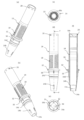
도 1은 본 개시의 제1 실시 형태에 관한 도포구의 설명도로서, (a)가 전체 정면도, (b)가 (a)의 B-B선에 따르는 종단면도, (c)가 선방부(先方部)의 확대 종단면도이다.
도 2는 도 1의 도포구의 선축으로부터 후축을 떼어낸 상태의 설명도로서, (a)가 전체 정면도, (b)가 (a)의 B-B선에 따르는 종단면도, (c)가 선방(先方)으로부터의 사시도이다.
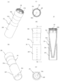
도 3은 도 1의 도포구에서의 선축의 부품도로서, (a)가 후방으로부터의 사시도, (b)가 선방으로부터의 사시도, (c)가 후방으로부터의 시도(視圖), (d)가 정면도, (e)가 선방으로부터의 시도, (f)가 (d)의 F-F선에 따르는 종단면도이다.
도 4는 도 1의 도포구에서의 캡의 부품도로서, (a)가 후방으로부터의 사시도, (b)가 선방으로부터의 사시도, (c)가 후방으로부터의 시도, (d)가 정면도, (e)가 선방으로부터의 시도, (f)가 (d)의 F-F선에 따르는 종단면도이다.
도 5는 도 1의 도포구의 후축의 종단한 부품도이다.
도 6은 도 1의 도포구의 내선축의 부품도로서, (a)가 후방으로부터의 사시도, (b)가 선방으로부터의 사시도, (c)가 후방으로부터의 시도, (d)가 정면도이다.
도 7은 본 개시의 제2 실시 형태에 관한 도포구의 설명도로서, (a)가 전체 정면도, (b)가 (a)의 B-B선에 따르는 종단면도, (c)가 선방부의 확대 종단면도이다.
도 8은 도 7의 도포구에서의 선축의 부품도로서, (a)가 후방으로부터의 사시도, (b)가 선방으로부터의 사시도, (c)가 후방으로부터의 시도, (d)가 정면도, (e)가 선방으로부터의 시도, (f)가 (d)의 F-F선에 따르는 종단면도이다.
도 9는 도 7의 도포구에서의 캡의 부품도로서, (a)가 후방으로부터의 사시도, (b)가 선방으로부터의 사시도, (c)가 후방으로부터의 시도, (d)가 정면도, (e)가 선방으로부터의 시도, (f)가 (a)의 F부의 상세도, (g)가 (d)의 G-G선에 따르는 종단면도이다.1 is an explanatory view of an applicator according to a first embodiment of the present disclosure, in which (a) is an overall front view, (b) is a longitudinal sectional view taken along line BB of (a), and (c) is a forward portion. ) is an enlarged longitudinal section of the
Figure 2 is an explanatory view of the state in which the rear shaft is removed from the front shaft of the applicator of Figure 1, (a) is the entire front view, (b) is a longitudinal cross-sectional view along line BB of (a), (c) is the front ) is a perspective view from
Figure 3 is a part view of the line shaft in the applicator of Figure 1, (a) is a perspective view from the rear, (b) is a perspective view from the front, (c) is a view from the rear, (d) is a perspective view Front view, (e) is a view from the forward direction, (f) is a longitudinal cross-sectional view along the FF line of (d).
Figure 4 is a part view of the cap in the applicator of Figure 1, (a) is a perspective view from the rear, (b) is a perspective view from the front, (c) is a view from the rear, (d) is a front view, (e) is a view from the forward direction, (f) is a longitudinal cross-sectional view along the FF line in (d).
Fig. 5 is a part view of the rear shaft of the applicator of Fig. 1 in a longitudinal sectional view.
Fig. 6 is a part view of the inner shaft of the applicator of Fig. 1, wherein (a) is a perspective view from the rear, (b) is a perspective view from the front, (c) is a view from the rear, and (d) is a front view.
7 is an explanatory view of an applicator according to a second embodiment of the present disclosure, in which (a) is an overall front view, (b) is a longitudinal sectional view taken along line BB of (a), and (c) is an enlarged longitudinal sectional view of a forward portion. am.
Figure 8 is a part view of the line shaft in the applicator of Figure 7, (a) is a perspective view from the rear, (b) is a perspective view from the front, (c) is a view from the rear, (d) is a front view, (e) is a view from the forward direction, (f) is a longitudinal cross-sectional view along the FF line in (d).
Figure 9 is a part view of the cap in the applicator of Figure 7, (a) is a perspective view from the rear, (b) is a perspective view from the front, (c) is a view from the rear, (d) is a front view, (e) is a view from the forward direction, (f) is a detailed view of part F in (a), and (g) is a longitudinal cross-sectional view along the GG line in (d).
이하, 본 개시의 실시 형태에 대해 첨부 도면을 참조하여 설명한다.EMBODIMENT OF THE INVENTION Hereinafter, embodiment of this disclosure is described with reference to accompanying drawings.
도 1은, 제1 실시 형태에 관한 도포구의 전체 설명도, 도 2가 리필 상태의 선축으로부터 후축을 떼어낸 상태의 설명도이다. 도 3이 선축, 도 4가 캡, 도 5가 후축의, 도 6이 내선축의 각 부품도이다.FIG. 1 is an overall explanatory diagram of the applicator according to the first embodiment, and FIG. 2 is an explanatory diagram of a state in which the rear shaft is removed from the front shaft in a refilled state. Fig. 3 is a part view of the front shaft, Fig. 4 is the cap, Fig. 5 is the rear shaft, and Fig. 6 is the inner shaft.
제1 실시 형태에 관한 도포구는, 도 1, 도 2에 도시되어 있는 것과 같이, 도포체(10)에 공급하는 액체 화장료 수용용의 도포액 탱크(12)를 장착하는 선축(14)과, 선축(14)에 후방으로부터 장착되어 도포액 탱크(12)를 덮는 후축(16)을 구비하고, 선축(14)의 외주에, 수 나사부(18)와, 수 나사부(18)의 후방에 위치하고 또한 둘레 방향을 따라서 형성된 제1 맞물림부(20)를 가지며(도 3 참조), 후축(16)(본체(16a))의 내주에, 수 나사부(18)에 나사 결합하기 위한 암 나사부(22)와, 제1 맞물림부(20)에 맞물리기 위한 제2 맞물림부(24)를 가진다(도 5 참조).As shown in FIGS. 1 and 2, the applicator according to the first embodiment includes a
도포구는, 도 1, 도 2에 도시되어 있는 것과 같이, 캡(26), 도포체(10), 선축(14), 내선축(34), 컬렉터(36) 및 도포액 탱크(12)를 부품 조립한 상태에서 리필(A)이 구성된다.As shown in FIGS. 1 and 2, the applicator includes a
도 3 및 도 4에 도시되어 있는 것과 같이, 도포체(10)를 덮기 위해 선축에 장착 가능한 캡(26)을 가지고, 캡(26) 내면에 제1 돌기부(28)를 형성하며, 선축(14) 외주면에 제2 돌기부(30)를 형성하고, 캡(26)을 선축(14)에 장착했을 경우에, 제1 돌기부(28) 및 제2 돌기부(30)끼리가 서로 맞물릴 수 있도록 구성된다. 제2 돌기부(30)는 선축(14)의 외주의 차양부(플랜지)(32) 단면(端面)에 형성되어 있다.As shown in FIGS. 3 and 4, it has a
본 도포구는, 선단측의 선축(14) 내에 내선축(34)을 매개로 하여 도포체(10)가 장착되고, 선축(14)의 후단측에 장착된 도포액 탱크(12) 내에 액체 화장료가 수용된다.In this applicator, the
선축(14) 내에 컬렉터(36)가 수용되고, 컬렉터(36)의 후방에 액체 화장료를 수용하는 도포액 탱크(12)가 장착된다. 선축(14)의 외주에 차양부(32)가 확경(擴徑)되고, 도 1에 도시되어 있는 것과 같이, 차양부(32)의 선측면(先側面)에 캡(26)이 맞닿으며, 차양부(32)의 후측면에 후축(16)의 전단(前端)이 맞닿는다.A
컬렉터(36)의 축중심을 관통하여 중계심(中繼芯)(38)이 배치된다. 중계심(38)은 액체의 화장료를 도포체(10)로 유도하는 것이다.A
도포구에서는, 선축(14) 내의 도포체(10)는, 그 전단부가 선축(14) 선단의 내선축(34)의 개구부(34b)(도 6 참조)로부터 돌출·노출하고 있다. 내선축(34)의 개구부(34b)의 내주면은, 도포체(10)의 외주에 접하고 있다.In the applicator, the front end of the coated
또, 선축(14) 내에서, 컬렉터(36) 내의 중계심(38)의 선단이 도포체(10)의 후단 내에 삽입되어, 화장료를 유도하는 구성으로 하고, 컬렉터(36)에서는 액체 화장료 유도홈(슬릿)을 경유하여 중계심(38)으로부터 도포체(10)로 액체 화장료를 유도하도록 한 도포구로 하고 있다. 또한, 컬렉터(36)에서, 중계심(38)은, 섬유 다발이나 수지제의 액체 화장료 유도홈을 형성한 유도체 구성으로 할 수도 있다.In addition, in the
또, 화장료 도포구는, 도 1에 도시되어 있는 것과 같이, 도포체(10)의 후단부는, 내부가 중공이고, 또한, 외부에 확경된 플랜지가 형성된다. 중공 내부에 중계심(38)의 선단부가 삽입되어 있다.In the cosmetic applicator, as shown in Fig. 1, the rear end of the
선축(14) 내에는, 복수개의 매엽체 사이에 액을 일시 보류(保留)하는 기능을 가지는 컬렉터(36)가 배치된다. 차양부(32)는, 컬렉터(36)의 선단에 의해 밀려 선축(14) 내에 고정된다. 컬렉터(36)의 중공 구멍(36a) 내의 중계심(38)은, 도포액 탱크(12) 내의 액체 화장료를 도포체(10)로 유도하는 구조이다.In the
선축(14) 후부 내에, 도포액 탱크(12)가 그 선단부가 내장되어 감착하는 것에 의해서 고정된다.In the rear part of the
[컬렉터(36)][Collector (36)]
컬렉터(36)의 내부에는, 도 1에 도시되어 있는 것과 같이, 선단으로부터 후단까지 축방향을 따르는 중공 구멍(36a)이 관통 형성되고, 당해 중공 구멍(36a) 내에 중계심(38)이 장착되어 있다. 컬렉터(36)의 외주부에는, 매엽체(36b)가 간격을 두고 복수 배열된다. 매엽체(36b) 사이에 그 모세관력에 의해서 액을 일시적으로 보류하는 컬렉터(36)의 기능을 발휘한다. 매엽체(36b)를 세로 방향(축방향)으로 잘라 넣도록 슬릿(도시 생략)이 형성된다. 컬렉터(36)는, 슬릿을 통해서 매엽체(36b)사이에 액체 화장료가 유입·유출 가능하게 되어 있다. 또, 중공 구멍(36a) 내에는 리브를 형성하고, 당해 리브에 의해 상기 중계심(38)을 지지하는 구조로 해도 괜찮다.Inside the
컬렉터(36)는, 선축(14)의 내부에 장착되어 있고, 당해 컬렉터(36)의 후단부에서, 중공 구멍(36a)과 슬릿이 도포액 탱크(12)의 전부(前部)의 개구에 대향하고 있다.The
컬렉터(36)의 중공 구멍(36a) 내에 장착된 중계심(38)의 후단면(후단부)이 도포액 탱크(12)에 노출되고, 중계심(38)이 도포액 탱크(12) 내의 액(액체 화장료)을 전방으로 향하게(도포체(10)를 향하게) 유도하는 구성이다.The rear end surface (rear end) of the
컬렉터(36)의 선단부는, 컵 모양을 나타내고, 그 컵의 선단부가 내선축(34) 내부에 형성된 내주면(34c)에 끼워 넣어져 꼭대기부(34a1)(도 6 참조)에 맞닿아 위치 결정된다. 또, 컬렉터(36)의 컵 모양의 선단부로 도포체(10)의 후단부(플랜지의 후단면)를 압압하고 있다. 또, 컬렉터(36) 내의 중계심(38)의 선단이 도포체(10)의 후단 공간 내에 삽입되어 있다. 컬렉터(36)의 후단부는 도포액 탱크(12)를 향해서 노출되어 있고, 기압이나 온도 변화 등에 의해서 도포액 탱크(12)의 내압이 오르면 도포액 탱크(12) 내의 액체 화장료가 슬릿을 경유하여 컬렉터(36)의 매엽체(36b) 사이에 보류된다. 선축(14)에는 컬렉터(36)에 대해서 내외를 기액(氣液) 치환을 위해서 통기(通氣)시키는 통기공(14b)이 형성되어 있다.The front end of the
그 통기공(14b)으로부터, 이 선축(14)의 내부에 외기가 유통되고, 따라서, 선축(14) 내에 수용된 컬렉터(36) 외주의 매엽체(36b)나 슬릿에 외기가 유통된다. 도포액 탱크(12)의 내압 변동이 있어도, 선축(14) 내의 통기에 의해서 완화되어, 도포체(10) 등으로부터의 액체 화장료의 내뿜음, 액체 화장료의 끊김 등을 방지하고 있다.From the
[도포액 탱크(12)][Coating liquid tank 12]
도포액 탱크(12)는, 도 1, 도 2에 도시되어 있는 것과 같이, 도포액 탱크(12)의 선방부(先方部)에, 선축(14)의 후부(차양부(32)보다도 후부) 내에 끼워 넣어지고, 그 선축(14) 내에 장착된 컬렉터(36)의 후부가, 도포액 탱크(12)의 선방 부 내에 인접하고 있다. 도포액 탱크(12) 내에는 액(도포액)과 함께 당해 액을 교반하기 위한 금속제 또는 수지제의 막대 모양(구 모양 등 적절한 형상이 가능)의 교반체(12a)가 수용되어 있다.As shown in FIGS. 1 and 2 , the
[선축(14)][Line axis (14)]
선축(14)은 도 3에 도시되어 있는 것과 같이, 전체가 개략 중공 통 모양을 나타내고, 선단부에서는 그 개구(14a)에 인접하여 후방의 둘레면부에는, 내주 및 외주 사이에 관통하는 공기 치환용의 통기공(14b)이 형성된다. 선축(14)의 후부의 외주에, 수 나사부(18)와, 수 나사부(18)의 후방에 위치하고 또한 둘레 방향을 따라서 형성된 제1 맞물림부(20)를 가진다.As shown in FIG. 3, the
구체적으로는, 선축(14)의 선단부의 통기공(14b)으로부터 후방의, 중앙부 부근에, 차양부(32)가 확경되어 구성된다. 차양부(32)로부터 후방부가 통 모양으로 연재(延在)하고, 그 후방부의 외주면에 수 나사부(18)가, 차양부(32)의 후단면에 인접하는 개소로부터 후부를 절반 정도가 남는 개소까지 형성된다. 수 나사부(18)는, 나사산 도중에 잘림이 있는 볼록한 모양의 수컷 나사산이 있다.Specifically, the
도 3에 도시되어 있는 것과 같이, 선축의 선축(14)의 통 모양의 후방부의 후단 부근에는, 제1 맞물림부(20)이 둘레 방향으로 돌기가 배열된 구조이다. 또한, 선축(14)의 후단부의 내주면에 내부 돌기(14c)가 둘레 방향으로 배열되고, 내부 돌기(14c)에 의해서, 도포액 탱크(12)를 맞물리게 하는 구조로 되어 있다.As shown in Fig. 3, near the rear end of the cylindrical rear portion of the
또, 외주 돌기(14d)의 후방이면서, 선축(14) 외주면에서 차양부(32)에 인접하는 전방에는, 선후(先後)를 따라서 세워 마련된 판 모양 리브로서, 외경 방향 단부가 가늘게 된 제2 돌기부(30)이 둘레 방향으로 복수 배열되어 돌출 형성된다. 제2 돌기부(30)는, 도 4에 도시되어 있는 것과 같이, 캡(26) 후단 내주면에 형성된 제1 돌기부(28)에 맞물려, 서로 맞물리는 구조가 되고, 선축(14)에 캡(26)을 끼운 상태에서는, 상대 회전이 규제되는 구조로 되어 있다.In addition, at the rear of the outer
또한, 선축(14)의 개구(14a)로부터 내부 후방에는, 내선축(34) 맞물림용의 단부(段部)(14e)가 형성된다. 선축(14)의 통기공(14b)과 차양부(32)와의 사이에는, 외주에 요철이 있는 외주 돌기(14d)가 형성된다. 제1 외주 돌기(14d)에는, 도 4에 도시되어 있는 것과 같이, 캡(26)의 걸림 돌기(26b)가 맞물려 선후 방향으로의 빠짐 방지를 하기 위한 것이다.In addition, an
[후축(16)][Rear axle (16)]
후축(16)은, 도 2에 도시되어 있는 것과 같이, 후단이 막힌 통 모양의 본체(16a)의 외주부에, 외면에 디자인이 입혀진 후단이 폐쇄된 외장통(外裝筒)(16b)이 감착이나 접착에 의해서 고정되어 있다.As shown in FIG. 2, in the
후축(16)은, 상세하게는, 도 5에 도시되어 있는 것과 같이, 후축(16)의 본체(16a)의 내주에, 수 나사부(18)에 나사 결합하기 위한 암 나사부(22)가 내향 나사산 모양으로 형성된다. 암 나사부(22)의 후방에 선축(14)의 제1 맞물림부(20)에 맞물리기 위한 제2 맞물림부(24)가 형성된다. 제2 맞물림부(24)는, 후축(16) 본체(16a)의 내주면의 전체 둘레에 걸쳐서 내향으로 볼록한 모양으로 돌출된 환상(環狀) 돌기(환상 리브)가 형성된다. 제2 맞물림부(24)는 제1 맞물림부(20)에 걸리고, 고정할 수 있는 구조이면, 요철부 등 그 외의 구조로 할 수 있다. 또, 후축(16)은 그 후단부가 막혀진 개략 통 모양을 나타낸다.As shown in FIG. 5 , in detail, the
후축(16)을 선축(14)에 장착할 때에는, 도 2에 도시되어 있는 것과 같이, 후축(16)의 선방(先方)을, 도포액 탱크(12)를 덮도록 하여, 선축(14)의 후부 외주에 끼운다. 그리고, 선축(14)의 수 나사부(18)에 후축(16) 암 나사부(22)를 나사 결합시켜 오른 나사 방향으로 돌려 넣고, 제1 맞물림부(20)를 제2 맞물림부(24)에 올라 타게 하여 긴밀하게 맞물리게 하여 고정하고, 도 1에 도시되어 있는 것과 같이 일체화한다. 선축(14)의 수 나사부(18)에 후축(16)의 암 나사부(22)를 나사 결합시켰을 때에, 제1 맞물림부(20)와 제2 맞물림부(24)가 올라 탔을 때 등에 서로 맞물리기 때문에, 사용자는 맞물리는 것을 손으로 느껴 선축(14)에 후축(16)이 맞물린 것을 용이하게 판단할 수 있다.When attaching the
[캡(26)][Cap (26)]
액체 화장료 도포구에서는, 도 1에 도시되어 있는 것과 같이, 도포체(10)를 덮기 위해 선축(14)에 장착 가능한 캡(26)을 가지고, 캡(26)의 내면에 제1 돌기부(28)를 형성하고, 도 3에 도시되어 있는 것과 같이, 선축(14)의 외주면에 제2 돌기부(30)를 형성하고 있으며, 캡(26)을 선축(14)에 장착하였을 경우에, 제1 돌기부(28) 및 제2 돌기부(30)끼리가 서로 맞물릴 수 있고, 제2 돌기부(30)는 선축(14)의 외주의 차양부(32) 단면(端面)에 형성되어 있다.In the liquid cosmetic applicator, as shown in FIG. 1, it has a
구체적으로는, 도 4에 도시되어 있는 것과 같이, 캡(26)은, 그 후단부의 내면에 선후를 따른 리브가 복수 둘레 방향으로 배열된 제1 돌기부(28)가 형성된다.Specifically, as shown in FIG. 4 , the
도 3에 도시되어 있는 것과 같이, 제2 돌기부(30)는, 선축(14)의 외주의 전체 둘레에 걸쳐서 외경 방향으로 돌출하는 차양부(플랜지)(32)의 선단 측면에 형성되어 있다. 제2 돌기부(30)는, 폭이 좁고 축방향으로 긴 벽 모양 또는 리브 모양으로 형성되어 있다.As shown in FIG. 3 , the
따라서, 캡(26)을 선축(14)에 장착하였을 경우에, 제1 돌기부(28) 및 제2 돌기부(30)끼리가 서로 맞물릴 수 있도록 구성된다. 후술하는 것과 같이 리필(A)을 교환할 때에, 캡(26)을 잡고 후축(16)을 돌리면, 캡(26)과 함께 선축(14)이 어긋나지 않게 회전하기 때문에, 후축(16)의 회전에 의해서 선축(14)에 대한 후축(16)의 장착, 분리를 확실하게 할 수 있다.Therefore, when the
또, 캡(26)은 그 외주면이 오목부(26a)를 형성한 것이다. 즉, 도 1, 도 4에 도시되어 있는 것과 같이, 오목부(26a)는 선후 방향의 중앙부의 외주면이, 선부(先部)(26f)·후부(26r)보다도 세경(細徑)으로 패인 형상으로 되어 있는 것으로, 캡(26) 전체가 개략 장구 모양을 나타내고 있다. 캡(26)은, 오목부(26a)가 형성되는 것에 의해서, 사용자가 캡(26)의 오목부(26a)에 손가락을 걸기 쉽고, 잡기 쉽워 장착, 분리하기 쉬운 작용 효과를 발휘한다.In addition, the
선부(26f)는, 후부(26r)로부터 연속하여 원추 형상의 내부통(26c)이 끝으로 갈수록 가늘어져 폐쇄된 것으로, 내부통(26c)의 외부에 원통 형상을 나타내고 선부(26f)가 일체로 형성된 것이다.The
또한, 캡(26)은, 그 내주부에, 제1 돌기부(28)에 인접하게 선방으로, 선축(14)의 외주 돌기(14d)에 맞물리는 고정용의 걸림 돌기(26b)가 복수 둘레 방향으로 배열하여 형성된다. 따라서, 외주 돌기(14d)에 걸림용 돌기(26b)를 걸림 고정시키면, 캡(26)이 선축(14)에 빠지기 어렵게 되어, 제1 돌기부(28) 및 제2 돌기부(30)끼리가 서로 맞물림 상태를 유지할 수 있으므로, 리필(A)로부터의 후축(16)의 장착, 분리를 확실하게 할 수 있다.Further, on the inner circumference of the
또, 캡(26)은, 리필(A)로서 거래할 때의 가(假)캡으로서, 리필(A)을 후축(16)에 장착하여 교환한 후에는, 캡(26)에 대신하여, 당초부터의 외주면에 의장을 입힌 화장 캡을 장착하는 구조로 할 수 있다.In addition, the
[내선축(34)][extension axis (34)]
도 1에 도시되어 있는 것과 같이, 선축(14)에는, 개구(14a)로부터 돌출하여, 선축(14) 내주에 내선축(34)이 마련되어 있다.As shown in FIG. 1 , the
상세하게는, 도 6에 도시되어 있는 것과 같이, 내선축(34)은, 선단의 개구부(34b)가 열린 개략 콘 형상의 통 모양을 나타내고, 후부의 내주면에 후방 방향의 삼각 형상이 돌출된 꼭대기부(34a1)를 가지는 리브(34a)가 형성되어 있다.Specifically, as shown in Fig. 6, the
내선축(34)의 후단으로부터 내부에 걸쳐서 평탄한 내주면(34c)이 약간 끝으로 갈수록 가늘어지는 테이퍼 모양 형성되고, 내주면(34c)에 면(面)하여 꼭대기부(34a1)가 내주 방향으로 단차 모양으로 돌출하도록 형성된다.From the rear end of the
또, 내선축(34)의 외주면에는, 축방향 중앙부 부근에 선축(14)의 내부의 단부(段部)(개구(14a)에 인접하는 단부(14e)(도 3 참조))에 맞물리기 위한 맞물림 단차(34d)가 형성되어 있다.Further, on the outer circumferential surface of the
내선축(34)은, 내부에 꼭대기부(34a1)가 있는 리브(34a)를 가지므로, 조립시에 도포체(10)를 장착할 때에, 리브(34a)의 꼭대기부(34a1)에서 도포체(10)가 빗겨지거나, 혹은 안내되므로, 도포체(10)의 각 섬유가 흐트러지지 않고 내선축(34) 내로 안내되어, 도포체(10)의 장착을 다시 하지 않고, 예쁘게 장착할 수 있다.Since the
또, 내선축(34)은, 선축(14)과 이색(二色) 성형 등에 의해서 일체 성형하는 것도 포함된다. 내선축(34)의 선축(14)과의 판별을 위해서 다른 색으로 하는 것이 바람직하다.In addition, the
[액체 화장료][Liquid cosmetics]
도포액 탱크(12)에 수용하는 액체 화장료는, 바람직하게는, 물과, 수용성 유기용제와, 피막 형성제와, 색재와, 방부제를 주요한 성분으로서 포함한다.The liquid cosmetic contained in the
구체적으로 설명하면 이용하는 색재로서는, 산화 티탄, 산화 철, 감청(紺靑), 군청(群靑) 등 중 적어도 1종을 이용할 수 있다. 산화 티탄은, 비중:3.8~4.2이고, 화장료 중의 입자 지름은 200~500nm인 것이 바람직하고, 산화 철은, 비중이 3.8~5.5이고, 화장료 중의 입자 지름은 90~600nm인 것이 바람직하며, 감청의 비중은, 1.8~1.9이고, 화장료 중의 입자 지름은 80~300nm인 것이 바람직하고, 군청의 비중은, 1.8~1.9이고, 화장료 중의 입자 지름은, 300~600nm인 것이 바람직하다. 여기서, 본 발명에서, 「입자 지름」은, 액체 화장료(25℃)를 동적 광산란법에 의한 입자 지름 측정기 FPAR-1000(오오츠카 덴시사제)에 의해 구한 값이다.Specifically, as the coloring material to be used, at least one of titanium oxide, iron oxide, Prussian blue, ultramarine blue, and the like can be used. Titanium oxide has a specific gravity of 3.8 to 4.2, and the particle diameter in cosmetics is preferably 200 to 500 nm, and iron oxide has a specific gravity of 3.8 to 5.5 and a particle diameter in cosmetics is preferably 90 to 600 nm. The specific gravity is 1.8 to 1.9, the particle diameter in cosmetics is preferably 80 to 300 nm, the specific gravity of ultramarine blue is 1.8 to 1.9, and the particle diameter in cosmetics is preferably 300 to 600 nm. Here, in the present invention, "particle diameter" is a value determined for liquid cosmetics (25 ° C.) by a particle diameter measuring instrument FPAR-1000 (manufactured by Otsuka Electronics Co., Ltd.) by a dynamic light scattering method.
그 밖에 이용할 수 있는 색재(色材)로서는, 예를 들면, 청색 1호 Al 레이크, 적색 202호, 적색 220호, 적색 226호, 적색 228호, 청색 201호, 청색 204호, 청색 404호, 황색 401호, 황색 205호, 황색 4호 Al 레이크, 황색 203호 Al 레이크, 적색 104호 Al 레이크, 카본 블랙, 카르민(carmine) 등의 유기 안료나, 적색 2호, 적색 3호(FD&C Red No.3), 적색 40호(FD&C Red No.40), 적색 102호, 적색 104호(D&C Red No.28), 적색 105호, 적색 106호, 적색 201호(D&C Red No.6), 적색 202호(D&C Red No.7), 적색 203호, 적색 205호, 적색 227호(D&C Red No.33), 적색 230-1호(D&C Red No.22), 적색 401호, 적색 402호, 적색 504호(FD&C Red No.4), 등(橙)색 205호(D&C Orange No.4), 등색 402호, 황색 4호(FD&C Yellow No.5), 황색 5호(FD&C Yellow No.6), 황색 203호(D&C Yellow No.10), 황색 402호, 황색 403-1호(Ext. D&C Yellow No.7), 황색 406호, 황색 407호, 녹색 3호(FD&C Green No.3), 녹색 201호, 녹색 402호, 청색 1호(FD&C Blue No.1), 청색 2호(FD&C Blue No.2), 청색 203호, 청색 205호(D&C Blue No.4), 청색 403호, 청색 404호, 갈색 201호(D&C Brown No.1), 자(紫)색 401호(Ext. D&C Violet No.2), 흑색 401호 등의 산성 염료나, 앞서 설명한 산화 티탄, 산화 철, 감청, 군청 등의 무기 안료로부터 선택되는 적어도 1종을 들 수 있고, 수성 화장료에 이용되고 있는 색재이면, 특별히 한정되는 것이 아니다.As other colorants that can be used, for example, Blue No. 1 Al Lake, Red No. 202, Red No. 220, Red No. 226, Red No. 228, Blue No. 201, Blue No. 204, Blue No. 404, Yellow No. 401, Yellow No. 205, Yellow No. 4 Al Lake, Yellow No. 203 Al Lake, Red No. 104 Al Lake, carbon black, organic pigments such as carmine, Red No. 2, Red No. 3 (FD&C Red No.3), Red No. 40 (FD&C Red No.40), Red No.102, Red No.104 (D&C Red No.28), Red No.105, Red No.106, Red No.201 (D&C Red No.6), Red No.202 (D&C Red No.7), Red No.203, Red No.205, Red No.227 (D&C Red No.33), Red No.230-1 (D&C Red No.22), Red No.401, Red No.402 , Red No.504 (FD&C Red No.4), Orange No.205 (D&C Orange No.4), Orange No.402, Yellow No.4 (FD&C Yellow No.5), Yellow No.5 (FD&C YellowNo. 6), Yellow No.203 (D&C Yellow No.10), Yellow No.402, Yellow No.403-1 (Ext. D&C Yellow No.7), Yellow No.406, Yellow No.407, Green No.3 (FD&C GreenNo.3 ), Green No. 201, Green No. 402, Blue No. 1 (FD&C BlueNo.1), Blue No. 2 (FD&C BlueNo.2), Blue No. 203, Blue No. 205 (D&C BlueNo.4), Blue No. 403 , Blue No. 404, Brown No. 201 (D&C "Brown" No. 1), Purple No. 401 (Ext. D & C "Violet" No. 2), and acid dyes such as Black No. 401, titanium oxide, iron oxide, At least one selected from inorganic pigments such as Prussian blue and ultramarine blue is exemplified, and it is not particularly limited as long as it is a color material used in water-based cosmetics.
이들 색재의 함유량은, 발색(發色)성, 바람직한 점성, 도포체를 구비한 수성 화장료 도포구에서의 스무스한 토출성 등의 점에서, 액체 화장료 전량에 대해, 0.05~30%가 바람직하고, 보다 바람직하게는, 0.1~20%가 바람직하다.The content of these colorants is preferably 0.05 to 30% with respect to the total amount of liquid cosmetics in terms of color development, desirable viscosity, and smooth ejection property from a water-based cosmetic applicator equipped with a coating body, etc. More preferably, 0.1 to 20% is preferable.
이용할 수 있는 수용성 유기용제로서는, 화장품에 일반적으로 이용되고 있는 것이면, 특별히 한정되지 않고 어느 것도 사용할 수 있다. 예를 들면, 에탄올, 이소프로파놀, 페녹시 에탄올 등을 들 수 있다.Any water-soluble organic solvent that can be used is not particularly limited as long as it is generally used for cosmetics. For example, ethanol, isopropanol, phenoxyethanol, etc. are mentioned.
이들 수용성 유기용제의 함유량은, 액체 화장료 전량에 대해서, 바람직하게는, 0~20%이며, 보다 바람직하게는, 8~15%이다.The content of these water-soluble organic solvents is preferably 0 to 20%, more preferably 8 to 15% of the total amount of liquid cosmetics.
이용할 수 있는 피막 형성제로서는, 예를 들면, 아크릴산, 메타크릴산 혹은 그들의 알킬에스테르 또는 유도체, 스틸렌, 아세트산비닐 중의 1종 또는 2종 이상의 모노머로부터 선택되어 이루어지는 공중합체의 에멀젼 수지를 들 수 있다.Examples of usable film forming agents include emulsion resins of copolymers selected from one or two or more monomers selected from acrylic acid, methacrylic acid or alkyl esters or derivatives thereof, styrene, and vinyl acetate.
이들 피막 형성제(에멀젼 수지)의 함유량은, 고형분(수지분) 환산으로 액체 화장료 전량에 대해서, 2~15%가 바람직하고, 보다 바람직하게는, 2~10%로 하는 것이 바람직하다.The content of these film forming agents (emulsion resin) is preferably 2 to 15%, more preferably 2 to 10%, based on the total amount of liquid cosmetics in terms of solid content (resin content).
이용하는 액체 화장료는, 물(정제수, 증류수, 이온 교환수, 순수, 초순수 등을 포함함)을 용매로 한다. 이 물의 함유량은, 상기 각 성분, 후술하는 임의 성분을 함유한 잔부가 되는 것이다.The liquid cosmetics used use water (including purified water, distilled water, ion-exchanged water, pure water, ultrapure water, etc.) as a solvent. The content of this water is the remainder containing each of the above components and optional components to be described later.
또한, 이용하는 액체 화장료에는, 상기 각 성분들 외에, 통상의 액체 화장료에 이용되는 임의 성분 등을 함유하게 할 수 있다. 구체적으로는, 방부제, 산화 방지제, 중화제, 자외선 흡수제, 킬레이트제, 보습제, 미용 성분, 향료, 점도 조정제 등을, 본 발명의 효과를 해치지 않는 범위에서 적절 양을 함유시킬 수 있다.In addition, the liquid cosmetics to be used may contain, in addition to the above components, arbitrary components used in general liquid cosmetics. Specifically, antiseptic agents, antioxidants, neutralizers, ultraviolet absorbers, chelating agents, moisturizing agents, cosmetic ingredients, fragrances, viscosity modifiers and the like can be incorporated in appropriate amounts within a range that does not impair the effects of the present invention.
이용하는 액체 화장료에서는, 바람직하게는, 도포액을 도포구로부터 스무스하게 토출하게 하는 점, 양호한 도포 성능을 발휘하게 하는 점 등에서, ELD형 점도계에 의한 온도 25℃, 시어(shear) 속도 76.6S-1에서의 점도가 2~9mPa·s의 범위로 하는 것이 바람직하고, 또, 액체 화장료의 표면 장력이 34mN/m 이상인 것이 바람직하다. 또한, 표면 장력은, 쿄와 가이멘카가쿠사제의 CBVP-Z형 표면 장력계(플레이트법)를 이용하여 온도 25℃에서 얻어진 측정값을 말한다.In the liquid cosmetics to be used, it is preferable to smoothly discharge the coating liquid from the applicator and to exhibit good coating performance at a temperature of 25°C and a shear rate of 76.6S -1 using an ELD viscometer. It is preferable that the viscosity in is in the range of 2 to 9 mPa·s, and it is preferable that the surface tension of the liquid cosmetic is 34 mN/m or more. In addition, surface tension refers to the measured value obtained at the temperature of 25 degreeC using the CBVP-Z surface tensiometer (plate method) by Kyowa Science and Technology Co., Ltd. product.
[리필(A)][Refill (A)]
여기서, 도 2에 도시되어 있는 것과 같이, 캡(26), 도포체(10), 선축(14), 내선축(34), 컬렉터(36), 중계심(38) 및 도포액 탱크(12)를 부품 조립한 상태에서 리필(A)이 구성된다. 교환용의 리필(A)로서 시장에서 판매할 수 있다.Here, as shown in FIG. 2, the
제1 실시 형태에 관한 액체 화장료 도포구에 의하면, 도 2에 도시되어 있는 것과 같이, 선축(14)의 외주에, 수 나사부(18)와, 수 나사부(18)의 후방에 위치하고 또한 둘레 방향을 따라서 형성된 제1 맞물림부(20)를 가지고, 후축(16)의 내주에, 수 나사부(18)에 나사 결합하기 위한 암 나사부(22)와, 제1 맞물림부(20)에 맞물리기 위한 제2 맞물림부(24)를 가지므로, 선축(14)의 수 나사부(18)에 후축(16)의 암 나사부(22)를 나사 결합시켰을 때에, 제1 맞물림부(20)와 제2 맞물림부(24)가 올라 탔을 때 등에 서로 맞물리기 때문에, 사용자는 맞물리는 것을 손으로 느껴 선축(14)에 후축(16)이 맞물린 것을 용이하게 판단할 수 있다고 하는 뛰어난 효과를 발휘할 수 있다.According to the liquid cosmetic applicator according to the first embodiment, as shown in FIG. 2, the external circumference of the
또, 도 2에 도시되어 있는 것과 같이, 도포체(10), 선축(14), 내선축(34), 컬렉터(36), 중계심(38) 및 도포액 탱크(12)를 부품 조립한 상태에서 리필(A)이 구성된다. 교환용의 리필(A)로서 시장에서 판매할 수 있다. 캡(26)을 잡고 후축(16)을 돌려 넣을 때에, 캡(26)의 제1 돌기부(28)가 선축(14)의 제2 돌기부(30)에 맞물려 있기 때문에(도 3, 도 4 참조), 캡(26)이 선축(14)에 대해서 상대 회전이 규제되므로, 선축(14)을 후축(16)이 스무스하게 나사 결합하고, 제1 맞물림부(20)이 제2 맞물림부(24)에 긴밀하게 맞물릴 때까지 후축(16)을 완전히 돌릴 수 있어서 실수없이 장착할 수 있다.In addition, as shown in FIG. 2, the
다음으로, 제2 실시 형태에 관한 도포구를 설명한다.Next, the applicator according to the second embodiment will be described.
도 7은, 제2 실시 형태에 관한 도포구의 전체 설명도, 도 8은, 선축(14B)의 부품도, 도 9는, 캡(26B)의 부품도이다. 이들 도면에서, 제2 실시 형태에 관한 도포구는, 제1 실시 형태와 마찬가지의 부분에 동일한 부호를 붙이고 있다.Fig. 7 is an overall explanatory view of the applicator according to the second embodiment, Fig. 8 is a parts view of the
도포구는, 도 7에 도시되어 있는 것과 같이, 캡(26B), 도포체(10), 선축(14B), 컬렉터(36) 및 도포액 탱크(12)를 부품 조립한 상태의 리필(B)을 구비하여 구성된다. 제1 실시 형태의 도포구는, 캡(26B)의 전체 구성과 선축(14B)의 일부 구성이 다르고, 그 외에는 마찬가지이다.As shown in FIG. 7, the applicator is a refill B in which the
도포구는, 도 7~도 9에 도시되어 있는 것과 같이, 도포체(10)를 덮기 위해 선축(14B)에 장착 가능한 캡(26B)을 가지고, 캡(26B) 후단부(선축(14B)를 끼워 넣는 측부)의 내면에 제1 돌기부(28B)를 형성하고, 선축(14B) 외주면에 제2 돌기부(30B)를 형성하며, 캡(26B)을 선축(14B)에 장착했을 경우에, 제1 돌기부(28B) 및 제2 돌기부(30B)끼리가 서로 맞물려 빠짐 방지 가능하게 구성된다. 제2 돌기부(30B)는 선축(14B)의 외주의 차양부(플랜지)(32)의 전측 단면으로부터 연재하여 형성되어 있다.As shown in Figs. 7 to 9, the applicator has a
[선축(14B)][Line axis (14B)]
도 8에 도시되어 있는 것과 같이, 선축(14B)은, 선단부까지 일체로 형성되어 있고, 제1 실시 형태의 별체의 내선축(34)의 마찬가지 구조를 선축(14B)의 선단부(14Bf)에 구비하고 있다. 또, 제1 맞물림부(20B)는 둘레 방향으로 긴 리브 모양으로 형성되어 있다.As shown in Fig. 8, the
선축(14B)은, 전체가 개략 중공 통 모양을 나타내고, 선단부(14Bf)에서는 선단의 개구(14Ba)로부터 후방의 테이퍼 모양으로 확경되는 둘레면부에는, 내주 및 외주 사이에 관통하는 공기 치환용의 통기공(14bb)가 형성된다.The
선단부(14Bf)는, 제1 실시 형태의 내선축(34)과 마찬가지 구성이 선축(14B)에 일체화된 중공 테이퍼 모양의 구성을 가진다. 통기공(14bb)의 위치의 내측에는 단부(段部)(14Bc)가 있고, 단부 내주가 개구(14Ba)에 연속하는 테이퍼 구멍으로 되어 있다. 단부(14Bc)로부터 선방의, 선단부(14Bf)의 내주면에는, 그 내측에 도포체(10)와 함께 컬렉터(36)의 컵 모양의 선단부를 들어가게 하여 위치 결정하는 테이퍼 모양의 위치 결정부(14Bd)가 형성된다. 또, 그 위치 결정부(14Bd)보다 전방의 내주면에 후방 방향의 삼각 형상의 돌출된 꼭대기부(34Ba1)를 가지는 리브(34Ba)가 형성되어 있다.The distal end portion 14Bf has a hollow tapered configuration in which a configuration similar to that of the
선축(14B)에서, 차양부(32)의 후방의 외주에는, 수 나사부(18B)와, 수 나사부(18B)의 후방에 위치하고 또한 둘레 방향을 따라서 길게 형성된 제1 맞물림부(20B)를 가진다. 수 나사부(18B)는, 나사산 도중에 끊김이 없는 볼록한 모양의 수 나사산으로 되어 있다.The
또, 선축(14B)의 외주 돌기(14d)의 후방이고, 차양부(32)에 인접하는 외주면의 전방에는, 선후를 따라서 세우 마련된 판 모양 리브로서, 외경 방향의 외측 단부가 평탄하게 된 제2 돌기부(30B)가 둘레 방향으로 복수 배열되어 돌출 형성된다.Further, in front of the outer circumferential surface adjacent to the
[캡(26B)][Cap (26B)]
도포구에서는, 도 7~도 9에 도시되어 있는 것과 같이, 도포체(10)를 덮기 위해 선축(14B)에 장착 가능한 캡(26B)을 가지고, 캡(26B)의 내면에 제1 돌기부(28B)를 형성하며, 선축(14B)의 외주면에 제2 돌기부(30B)를 형성하고 있고, 캡(26B)을 선축(14B)에 장착했을 경우에, 제1 돌기부(28B) 및 제2 돌기부(30B)끼리가 서로 맞물릴 수 있고, 제2 돌기부(30B)는 선축(14B)의 외주의 차양부(32) 단면(端面)에 형성되어 있다.As shown in FIGS. 7 to 9 , the applicator has a
구체적으로는, 도 9에 도시되어 있는 것과 같이, 캡(26B)은, 그 후단부의 내면에 선후를 따른 리브가 복수 둘레 방향으로 배열된 제1 돌기부(28B)가 형성된다. 이 제1 돌기부(28B)는, 도 9의 (f)에 도시되어 있는 것과 같이, 내주단(28Ba)이 평탄한 언덕 모양으로 형성되어 있다.Specifically, as shown in FIG. 9 , the
따라서, 캡(26B)을 선축(14B)에 장착했을 경우에, 제1 돌기부(28B) 및 제2 돌기부(30B)끼리가 서로 맞물릴 수 있게 구성된다.Therefore, when the
선축(14B)의 제2 돌기부(30)이, 캡(26B) 후단 내주면에 형성된 제1 돌기부(28B)에 맞물리고, 서로 맞물리는 구조로 되어 있으며, 선축(14B)에 캡(26B)을 끼운 상태에서는, 상대 회전이 규제되는 구조로 되어 있다.The
또, 제1 돌기부(28B)의 내주단(28Ba)이 평탄하고, 선축(14B)의 제2 돌기부(30B)는, 외경 방향의 외측 단부가 평탄하다.In addition, the inner circumferential end 28Ba of the
그 때문에, 캡(26B)을 선축(14B)에 장착할 때에, 제1 돌기부(28B) 및 제2 돌기부(30B)의 대향하는 선단부끼리가 평탄하게 구성되어 있기 때문에, 제1 돌기부(28B) 및 제2 돌기부(30B)끼리가 올라 타기 쉽게 된다. 올라 탄 후에 상대 회전시키면 제2 돌기부(30B)가 제1 돌기부(28B) 사이는 용이하게 끼워져 회전 규제된다. 또, 올라 타기 쉽게 힘을 분산할 수 있기 때문에, 제1 돌기부(28B) 및 제2 돌기부(30B) 중 일방 또는 쌍방이, 맞닿아 깨짐 등의 파손이 생기는 것을 확실히 방지할 수 있다.Therefore, when attaching the
또한, 리필(B)을 교환할 때에, 리필(A)과 마찬가지로, 캡(26B)을 잡고 후축(16)을 돌리면, 캡(26B)와 함께 선축(14B)이 어긋나지 않게 회전하기 때문에, 후축(16)의 회전에 의해서 선축(14B)에 대한 후축(16)의 장착, 분리를 확실하게 할 수 있다.In addition, when replacing the refill B, as in the case of the refill A, when the
또, 캡(26B)은 그 외주면이 오목부(26Ba)를 형성한 것이다. 즉, 도 9에 도시되어 있는 것과 같이, 오목부(26a)는 선후 방향의 중앙부의 외주면이, 선부(26Bf) 및 후부(26Br)보다도 세경(細徑)으로 패인 형상으로 된 것이고, 캡(26B) 전체가 개략 장구 모양을 나타내고 있다. 캡(26B)은, 오목부(26Ba)가 형성되는 것에 의해서, 제1 실시 형태와 마찬가지로, 사용자가 캡(26B)의 오목부(26a)에 손가락을 걸기 쉽고, 잡기 쉬어 장착, 분리하기 쉬운 작용 효과를 발휘한다.In addition, the
또, 선부(26Bf)는, 선단부가 평탄하게 폐쇄된 것이므로, 캡(26B)은 전체에 개략 장구 형상을 나타내고 있다. 제1 실시 형태와 같은 내부통(26c)은 구비하지 않고, 형상이 단순화되어 있다.Also, since the front end portion of the tip portion 26Bf is flatly closed, the
또, 캡(26B)의 내주부에는, 제1 돌기부(28B)에 인접하여 선방에, 선축(14B)의 외주 돌기(14d)에 맞물리는 고정용의 걸림 돌기(26Bb)가 복수 둘레 방향으로 배열되어 형성된다. 또, 도 9에 도시되어 있는 것과 같이, 걸림 돌기(26Bb)의 선방에는 축방향으로 긴 리브(26Be)가 내주면에 세워 마련되어 있고, 도 7에 도시되어 있는 것과 같이, 캡(26B)을 선축에 끼웠을 때에 선축(14B)를 주위로부터 지지하여, 캡(26B)의 덜거덕거림을 방지할 수 있다.Further, on the inner periphery of the
이상의 실시 형태는, 본 발명의 일례이며, 본 발명의 범위 내에서 변형 실시한 것도 기술적 범위 내인 것은 물론이다.The above embodiment is an example of the present invention, and it is needless to say that modified implementation within the scope of the present invention is also within the technical scope.
본 발명의 도포구는, 도포액의 도포구에 이용할 수 있다.The applicator of the present invention can be used as an applicator for a coating liquid.
10 : 도포체
12 : 도포액 탱크
14 : 선축
14c : 내부 돌기
14d : 외주 돌기
14e : 단부
14B : 선축
14Bf : 선단부
16 : 후축
16a : 본체
16b : 외장통
18 : 수 나사부
18B : 수 나사부
20 : 제1 맞물림부
20B : 제1 맞물림부
22 : 암 나사부
24 : 제2 맞물림부
26 : 캡
26a : 오목부
26b : 걸림 돌기
26c : 내부통
26f : 선부
26r : 후부
26B : 캡
26Ba : 오목부
26Bb : 걸림 돌기
26Be : 리브
26Bf : 선부
28 : 제1 돌기부
28B : 제1 돌기부
30 : 제2 돌기부
30B : 제2 돌기부
32 : 차양부
34 : 내선축
34a : 리브
34a1 : 꼭대기부
34b : 개구부
34c : 내주면
34d : 맞물림 단차
34Ba : 리브
34Ba1 : 꼭대기부
36 : 컬렉터
38 : 중계심
A : 리필
B : 리필10: coating body 12: coating liquid tank
14:
14d: outer
14B: front shaft 14Bf: front end
16:
16b: exterior cylinder 18: male thread
18B: male screw part 20: first engagement part
20B: first engagement part 22: female thread part
24: second engagement portion 26: cap
26a:
26c:
26r: rear 26B: cap
26Ba: concave portion 26Bb: snag protrusion
26Be: Rib 26Bf: Front part
28:
30:
32: awning part 34: inner shaft
34a: rib 34a1: top
34b:
34d: engagement step 34Ba: rib
34Ba1: top part 36: collector
38: intermediate core A: refill
B: Refill
Claims (4)
선축에 장착하여 도포액 탱크를 덮는 후축을 구비하고,
상기 선축의 외주에, 수 나사부와, 상기 수 나사부의 후방에 위치하고 또한 둘레 방향을 따라서 형성된 제1 맞물림부를 가지며,
상기 후축의 내주에, 상기 수 나사부에 나사 결합하기 위한 암 나사부와, 상기 제1 맞물림부에 맞물리기 위한 제2 맞물림부를 가지는 것을 특징으로 하는 도포구.A front shaft for mounting a coating liquid tank for accommodating a coating liquid supplied to the coated body;
Equipped with a rear shaft mounted on the front shaft to cover the coating liquid tank,
On the outer circumference of the line shaft, a male threaded portion and a first engaging portion located behind the male threaded portion and formed along the circumferential direction,
The applicator characterized in that it has a female threaded portion for screwing into the male threaded portion on an inner circumference of the rear shaft, and a second engaging portion for engaging with the first engaging portion.
상기 도포체를 덮기 위해 선축에 장착 가능한 캡을 가지고, 상기 캡 내면에 제1 돌기부를 형성하며, 상기 선축 외주면에 제2 돌기부를 형성하고, 상기 캡을 상기 선축에 장착했을 경우에, 상기 제1 돌기부 및 제2 돌기부끼리가 서로 맞물릴 수 있고, 제2 돌기부는 선축의 외주의 차양부 단면(端面)에 형성되어 있는 것을 특징으로 하는 도포구.The method of claim 1,
When a cap attachable to the line shaft is provided to cover the coated body, a first protrusion is formed on the inner surface of the cap, and a second protrusion is formed on the outer circumferential surface of the line shaft, and the cap is mounted on the line shaft, the first The applicator characterized in that the protrusions and the second protrusions can be engaged with each other, and the second protrusions are formed on the end face of the rim of the outer periphery of the line shaft.
상기 캡의 외주면에 오목부를 형성한 것을 특징으로 하는 도포구.The method of claim 2,
An applicator characterized in that a concave portion is formed on the outer circumferential surface of the cap.
상기 선축 내주에 내선축(內先軸)을 마련하고, 상기 내선축의 내주면에 삼각 형상의 꼭대기부를 형성한 것을 특징으로 하는 도포구. According to any one of claims 1 to 3,
An applicator characterized in that an internal wire shaft is provided on the inner circumference of the wire shaft, and a triangular top portion is formed on the inner circumferential surface of the wire shaft.
Applications Claiming Priority (3)
| Application Number | Priority Date | Filing Date | Title |
|---|---|---|---|
| JP2020139994 | 2020-08-21 | ||
| JPJP-P-2020-139994 | 2020-08-21 | ||
| PCT/JP2021/030471 WO2022039243A1 (en) | 2020-08-21 | 2021-08-19 | Applicator |
Publications (1)
| Publication Number | Publication Date |
|---|---|
| KR20230054392A true KR20230054392A (en) | 2023-04-24 |
Family
ID=80323507
Family Applications (1)
| Application Number | Title | Priority Date | Filing Date |
|---|---|---|---|
| KR1020237008376A KR20230054392A (en) | 2020-08-21 | 2021-08-19 | applicator |
Country Status (6)
| Country | Link |
|---|---|
| US (1) | US20230292910A1 (en) |
| EP (1) | EP4201252A4 (en) |
| JP (1) | JPWO2022039243A1 (en) |
| KR (1) | KR20230054392A (en) |
| CN (1) | CN116056802A (en) |
| WO (1) | WO2022039243A1 (en) |
Citations (1)
| Publication number | Priority date | Publication date | Assignee | Title |
|---|---|---|---|---|
| JP2018192242A (en) | 2017-05-16 | 2018-12-06 | 三菱鉛筆株式会社 | Applicator |
Family Cites Families (12)
| Publication number | Priority date | Publication date | Assignee | Title |
|---|---|---|---|---|
| US4289248A (en) * | 1979-10-15 | 1981-09-15 | Becton, Dickinson And Company | Container closure assembly having intermediate positioning means |
| FR2520328A1 (en) * | 1982-01-22 | 1983-07-29 | Chanel | DEVICE FOR PREVENTING THE SELF-DISCARDING OF A PLUG ON A BOTTLE |
| FR2564070B2 (en) * | 1983-10-13 | 1987-04-30 | Oreal | BOTTLE COMPRISING AN ANGULARLY ORIENTED CAPPING DEVICE RELATIVE TO THE BOTTLE AUDIT |
| AU9650098A (en) * | 1997-12-25 | 1999-07-19 | Mitsubishi Pencil Kabushiki Kaisha | Ball-point pen |
| JP3420078B2 (en) * | 1998-09-02 | 2003-06-23 | タチカワ株式会社 | Writing implement |
| JP4748897B2 (en) * | 2001-08-15 | 2011-08-17 | 三菱鉛筆株式会社 | Writing instrument |
| JP3133495U (en) * | 2007-05-01 | 2007-07-12 | パイロットインキ株式会社 | Ink tank exchangeable writing instrument |
| JP5486296B2 (en) * | 2009-12-25 | 2014-05-07 | 花王株式会社 | Applicator |
| JP2015165866A (en) * | 2014-03-04 | 2015-09-24 | 鈴野化成株式会社 | cartridge type cosmetic container |
| JP2020001193A (en) * | 2018-06-25 | 2020-01-09 | 株式会社パイロットコーポレーション | Thermochromic writing instrument |
| JP7158203B2 (en) * | 2018-08-07 | 2022-10-21 | 三菱鉛筆株式会社 | Applicator |
| JP7350487B2 (en) * | 2019-01-23 | 2023-09-26 | 三菱鉛筆株式会社 | cosmetic applicator |
-
2021
- 2021-08-19 US US18/021,614 patent/US20230292910A1/en active Pending
- 2021-08-19 EP EP21858386.2A patent/EP4201252A4/en active Pending
- 2021-08-19 JP JP2022544006A patent/JPWO2022039243A1/ja active Pending
- 2021-08-19 CN CN202180055893.8A patent/CN116056802A/en active Pending
- 2021-08-19 WO PCT/JP2021/030471 patent/WO2022039243A1/en unknown
- 2021-08-19 KR KR1020237008376A patent/KR20230054392A/en active Search and Examination
Patent Citations (1)
| Publication number | Priority date | Publication date | Assignee | Title |
|---|---|---|---|---|
| JP2018192242A (en) | 2017-05-16 | 2018-12-06 | 三菱鉛筆株式会社 | Applicator |
Also Published As
| Publication number | Publication date |
|---|---|
| EP4201252A1 (en) | 2023-06-28 |
| WO2022039243A1 (en) | 2022-02-24 |
| JPWO2022039243A1 (en) | 2022-02-24 |
| US20230292910A1 (en) | 2023-09-21 |
| CN116056802A (en) | 2023-05-02 |
| EP4201252A4 (en) | 2024-08-21 |
Similar Documents
| Publication | Publication Date | Title |
|---|---|---|
| JP7401175B2 (en) | applicator | |
| KR100897854B1 (en) | Tool for applying liquid cosmetic material | |
| KR200475064Y1 (en) | Eye liner | |
| JP2018192242A (en) | Applicator | |
| US3446563A (en) | Fiber-tip writing pen with replaceable cartridge | |
| CA1232573A (en) | Applicator tip assembly for a pen-like instrument | |
| KR20230054392A (en) | applicator | |
| JP6549473B2 (en) | Applicator | |
| JP2602464Y2 (en) | Liquid applicator | |
| KR102042589B1 (en) | Ball-type Eyeliner | |
| US11053056B2 (en) | Anti-clog cap and associated containers and methods | |
| JP6745387B2 (en) | Applicator | |
| JP4605341B2 (en) | Cosmetic storage application container | |
| JP5470173B2 (en) | Cap for writing instrument with clip and writing instrument | |
| JPH07299985A (en) | Writing implement | |
| JP3751378B2 (en) | Applicator brush mounting structure | |
| JPH077192Y2 (en) | Writing instrument | |
| JP7503688B2 (en) | Writing implements | |
| CN115211654B (en) | Cosmetic container with application member | |
| JPH0810405Y2 (en) | Ink tank type applicator | |
| WO2024029380A1 (en) | Cosmetic applicator | |
| JPS6112131Y2 (en) | ||
| BR112018010461B1 (en) | Ink cartridge and writing instrument | |
| JP2607230Y2 (en) | Writing implement | |
| JP2020092964A (en) | Applicator |
Legal Events
| Date | Code | Title | Description |
|---|---|---|---|
| A201 | Request for examination |