KR20230050428A - Image data creation method of dental sculpture, image data creation device of dental sculpture, image data creation program of dental sculpture, manufacturing method of dental sculpture, and dental sculpture - Google Patents
Image data creation method of dental sculpture, image data creation device of dental sculpture, image data creation program of dental sculpture, manufacturing method of dental sculpture, and dental sculpture Download PDFInfo
- Publication number
- KR20230050428A KR20230050428A KR1020237008652A KR20237008652A KR20230050428A KR 20230050428 A KR20230050428 A KR 20230050428A KR 1020237008652 A KR1020237008652 A KR 1020237008652A KR 20237008652 A KR20237008652 A KR 20237008652A KR 20230050428 A KR20230050428 A KR 20230050428A
- Authority
- KR
- South Korea
- Prior art keywords
- image data
- dental
- reinforcing member
- molding
- denture base
- Prior art date
Links
Images


Classifications
-
- A—HUMAN NECESSITIES
- A61—MEDICAL OR VETERINARY SCIENCE; HYGIENE
- A61C—DENTISTRY; APPARATUS OR METHODS FOR ORAL OR DENTAL HYGIENE
- A61C13/00—Dental prostheses; Making same
- A61C13/0003—Making bridge-work, inlays, implants or the like
- A61C13/0004—Computer-assisted sizing or machining of dental prostheses
-
- A—HUMAN NECESSITIES
- A61—MEDICAL OR VETERINARY SCIENCE; HYGIENE
- A61C—DENTISTRY; APPARATUS OR METHODS FOR ORAL OR DENTAL HYGIENE
- A61C13/00—Dental prostheses; Making same
- A61C13/0003—Making bridge-work, inlays, implants or the like
- A61C13/0006—Production methods
- A61C13/0013—Production methods using stereolithographic techniques
-
- A—HUMAN NECESSITIES
- A61—MEDICAL OR VETERINARY SCIENCE; HYGIENE
- A61C—DENTISTRY; APPARATUS OR METHODS FOR ORAL OR DENTAL HYGIENE
- A61C13/00—Dental prostheses; Making same
- A61C13/0003—Making bridge-work, inlays, implants or the like
- A61C13/0006—Production methods
- A61C13/0019—Production methods using three dimensional printing
-
- A—HUMAN NECESSITIES
- A61—MEDICAL OR VETERINARY SCIENCE; HYGIENE
- A61C—DENTISTRY; APPARATUS OR METHODS FOR ORAL OR DENTAL HYGIENE
- A61C13/00—Dental prostheses; Making same
- A61C13/01—Palates or other bases or supports for the artificial teeth; Making same
-
- A—HUMAN NECESSITIES
- A61—MEDICAL OR VETERINARY SCIENCE; HYGIENE
- A61C—DENTISTRY; APPARATUS OR METHODS FOR ORAL OR DENTAL HYGIENE
- A61C9/00—Impression cups, i.e. impression trays; Impression methods
- A61C9/004—Means or methods for taking digitized impressions
- A61C9/0046—Data acquisition means or methods
-
- B—PERFORMING OPERATIONS; TRANSPORTING
- B33—ADDITIVE MANUFACTURING TECHNOLOGY
- B33Y—ADDITIVE MANUFACTURING, i.e. MANUFACTURING OF THREE-DIMENSIONAL [3-D] OBJECTS BY ADDITIVE DEPOSITION, ADDITIVE AGGLOMERATION OR ADDITIVE LAYERING, e.g. BY 3-D PRINTING, STEREOLITHOGRAPHY OR SELECTIVE LASER SINTERING
- B33Y50/00—Data acquisition or data processing for additive manufacturing
-
- B—PERFORMING OPERATIONS; TRANSPORTING
- B33—ADDITIVE MANUFACTURING TECHNOLOGY
- B33Y—ADDITIVE MANUFACTURING, i.e. MANUFACTURING OF THREE-DIMENSIONAL [3-D] OBJECTS BY ADDITIVE DEPOSITION, ADDITIVE AGGLOMERATION OR ADDITIVE LAYERING, e.g. BY 3-D PRINTING, STEREOLITHOGRAPHY OR SELECTIVE LASER SINTERING
- B33Y80/00—Products made by additive manufacturing
-
- B—PERFORMING OPERATIONS; TRANSPORTING
- B29—WORKING OF PLASTICS; WORKING OF SUBSTANCES IN A PLASTIC STATE IN GENERAL
- B29C—SHAPING OR JOINING OF PLASTICS; SHAPING OF MATERIAL IN A PLASTIC STATE, NOT OTHERWISE PROVIDED FOR; AFTER-TREATMENT OF THE SHAPED PRODUCTS, e.g. REPAIRING
- B29C64/00—Additive manufacturing, i.e. manufacturing of three-dimensional [3D] objects by additive deposition, additive agglomeration or additive layering, e.g. by 3D printing, stereolithography or selective laser sintering
- B29C64/10—Processes of additive manufacturing
- B29C64/106—Processes of additive manufacturing using only liquids or viscous materials, e.g. depositing a continuous bead of viscous material
- B29C64/124—Processes of additive manufacturing using only liquids or viscous materials, e.g. depositing a continuous bead of viscous material using layers of liquid which are selectively solidified
-
- B—PERFORMING OPERATIONS; TRANSPORTING
- B29—WORKING OF PLASTICS; WORKING OF SUBSTANCES IN A PLASTIC STATE IN GENERAL
- B29C—SHAPING OR JOINING OF PLASTICS; SHAPING OF MATERIAL IN A PLASTIC STATE, NOT OTHERWISE PROVIDED FOR; AFTER-TREATMENT OF THE SHAPED PRODUCTS, e.g. REPAIRING
- B29C64/00—Additive manufacturing, i.e. manufacturing of three-dimensional [3D] objects by additive deposition, additive agglomeration or additive layering, e.g. by 3D printing, stereolithography or selective laser sintering
- B29C64/30—Auxiliary operations or equipment
- B29C64/386—Data acquisition or data processing for additive manufacturing
-
- B—PERFORMING OPERATIONS; TRANSPORTING
- B29—WORKING OF PLASTICS; WORKING OF SUBSTANCES IN A PLASTIC STATE IN GENERAL
- B29C—SHAPING OR JOINING OF PLASTICS; SHAPING OF MATERIAL IN A PLASTIC STATE, NOT OTHERWISE PROVIDED FOR; AFTER-TREATMENT OF THE SHAPED PRODUCTS, e.g. REPAIRING
- B29C64/00—Additive manufacturing, i.e. manufacturing of three-dimensional [3D] objects by additive deposition, additive agglomeration or additive layering, e.g. by 3D printing, stereolithography or selective laser sintering
- B29C64/40—Structures for supporting 3D objects during manufacture and intended to be sacrificed after completion thereof
-
- B—PERFORMING OPERATIONS; TRANSPORTING
- B33—ADDITIVE MANUFACTURING TECHNOLOGY
- B33Y—ADDITIVE MANUFACTURING, i.e. MANUFACTURING OF THREE-DIMENSIONAL [3-D] OBJECTS BY ADDITIVE DEPOSITION, ADDITIVE AGGLOMERATION OR ADDITIVE LAYERING, e.g. BY 3-D PRINTING, STEREOLITHOGRAPHY OR SELECTIVE LASER SINTERING
- B33Y10/00—Processes of additive manufacturing
Landscapes
- Health & Medical Sciences (AREA)
- Oral & Maxillofacial Surgery (AREA)
- Animal Behavior & Ethology (AREA)
- Dentistry (AREA)
- Epidemiology (AREA)
- Life Sciences & Earth Sciences (AREA)
- General Health & Medical Sciences (AREA)
- Public Health (AREA)
- Veterinary Medicine (AREA)
- Manufacturing & Machinery (AREA)
- Engineering & Computer Science (AREA)
- Materials Engineering (AREA)
- Chemical & Material Sciences (AREA)
- Dental Prosthetics (AREA)
Abstract
치과 조형물의 화상 데이터 작성 방법은 편자 형상의 오목부를 형성하는 측벽부를 갖는 치과 조형물의 화상 데이터를 취득하는 공정과, CAD로 측벽부를 보강하는 보강 부재의 화상 데이터를 작성하는 공정과, 치과 조형물의 화상 데이터와 보강 부재의 화상 데이터를 연결하는 공정을 갖는다.A method for creating image data of a dental object includes a step of acquiring image data of a dental object having a side wall portion forming a horseshoe-shaped concave portion, a step of creating image data of a reinforcing member reinforcing the side wall portion with CAD, and an image of the dental object object. It has a step of linking the data and the image data of the reinforcing member.

Description
본 개시는 치과 조형물의 화상 데이터 작성 방법, 치과 조형물의 화상 데이터 작성 장치, 치과 조형물의 화상 데이터 작성 프로그램, 치과 조형물의 제조 방법 및 치과 조형물에 관한 것이다.The present disclosure relates to a method for creating image data of a dental implant, an apparatus for generating image data of a dental implant, an image data creation program for a dental implant, a manufacturing method for a dental implant, and a dental implant.
근래, 광조 형식의 3D 프린터로 의치상, 마우스피스 혹은 치과용 모형과 같은 치과 조형물을 조형하는 기술이 제안되고 있다. 여기에서, 「치과 조형물」이란, 환자의 치조 융선(alveolar ridge)에 감합 가능한 형상을 가지며, 주로 치과 분야에서의 치료, 연구, 교육 등의 장면에서 사용되는 조형물이다.Recently, a technique for modeling a dental sculpture such as a denture base, a mouthpiece, or a dental model using a stereoscopic 3D printer has been proposed. Here, a "dental object" is an object that has a shape that can be fitted to the patient's alveolar ridge and is mainly used in situations such as treatment, research, and education in the field of dentistry.
예를 들면, 매달림형의 광조 형식의 3D 프린터에서는, 액조에 저류되어 있는 액상의 자외선(UV 광) 경화 수지액에, 조형하고 싶은 형상의 단면 데이터에 기초하여 UV 광이 조사되는 것에 의해, 수지의 얇은 경화층이 형성된다. 액조의 상측에는 빌드 테이블이 배치되며, 빌드 테이블에는 의치상이 서포트 핀에 의해 매달린다. 빌드 테이블을 서서히 상승시키면서, 경화층에 추가로 새로운 층을 1층씩 순차 적층해가는 공정을 반복하여, 최종적으로 소망하는 의치상이 조형된다.For example, in a 3D printer of a hanging light control type, a liquid ultraviolet (UV light) curing resin liquid stored in a liquid tank is irradiated with UV light based on cross-sectional data of a shape to be molded, A thin cured layer of is formed. A build table is disposed above the liquid tank, and a denture base is suspended from the build table by support pins. While gradually raising the build table, the process of sequentially laminating new layers one by one in addition to the hardened layer is repeated, and finally a desired denture base is formed.
이러한 광조 형식의 3D 프린터에서 사용되는 단면 데이터로서의 제조용 데이터는, 예를 들면 특허 문헌 1과 같은 CAD/CAM(Computer Aided Design and Computer Aided Manufacturing) 시스템을 이용하여 작성할 수 있다. 치과 조형물의 조형 작업에, CAD/CAM 시스템 및 광조 형식의 3D 프린터를 도입하는 것에 의해, 작업의 효율화가 도모되고, 품질의 불균일을 억제하는 것이 가능하게 된다는 메리트를 얻을 수 있다.Manufacturing data as cross-section data used in such a stereotype 3D printer can be created using a CAD/CAM (Computer Aided Design and Computer Aided Manufacturing) system such as
여기에서, 1층씩 얇은 경화층을 적층해가는 광조 형식의 3D 프린터를 조형 장치로서 이용한 적층 조형에서는, 예를 들면 오버행 형상과 같이 조형 대상물의 형상에 따라서는 경화층을 적층할 수 없는 경우나, 적층되는 경화층을 빌드 테이블의 하측에 매다는 경우가 있다. 이러한 조형의 경우, 빌드 테이블에서 서포트재를 연장하여 조형중의 조형 대상물을 조형 대상물의 외측으로부터 지지하는 수법이 채용된다.Here, in multilayer molding using a stereoscopic 3D printer in which thin hardened layers are laminated layer by layer as a molding device, for example, cases where the hardened layer cannot be laminated depending on the shape of the object to be molded, such as an overhang shape, There is a case where the cured layer to be laminated is suspended below the build table. In the case of such a molding, a technique is adopted in which a support material is extended from the build table to support the object being built from the outside of the object being built.
그러나, 치과 조형물이, 예를 들면 치조 융선의 잇몸이 끼워지는 편자 형상(즉, U자 형상)의 오목부가 형성된 의치상일 때, 의치상을 서포트재로 지지하여도, 오목부를 형성하는 측벽부가 무너져 오목부의 홈폭이 설계치보다 넓어지는 경우가 있다. 측벽부의 무너짐은 조형 중에 조형 대상물에 가해지는 중력이나, 냉각에 의해 고화될 때의 수지의 수축에 기인한다. 그 결과, 조형된 의치상을 환자의 잇몸에 장착했을 때, 의치상이 흔들리는 것과 같은 불편함이 생기는 경우가 있다.However, when the dental molding is, for example, a denture base having a horseshoe-shaped (ie, U-shaped) concave portion in which the gum of the alveolar ridge is fitted, even if the denture base is supported by a support material, the side wall portion forming the concave portion collapses and becomes concave. There is a case where the negative groove width is wider than the design value. Collapse of the side wall portion is caused by gravity applied to the object during molding or shrinkage of the resin when it is solidified by cooling. As a result, when the molded denture base is attached to the patient's gums, discomfort such as shaking of the denture base may occur.
이 불편함을 개선하기 위해, 3D 프린터에 단면 데이터로서의 슬라이스 데이터를 송신하는 CAM에 의해, 의치상의 측벽부를 보강하는 보강 부재를 형성하는 화상 데이터를 작성하는 것도 고려할 수 있다. 그러나, 본래, CAM은 CAD로 작성된 화상 데이터를 입력 데이터로서, 3D 프린터의 생산 준비 전반을 컴퓨터 상에서 실행하기 위해 이용되는 소프트웨어 시스템이다. 이 때문에, 보강 부재를 형성하는 화상 데이터를 CAM에 의해 적절히 작성하는 것은 어려우며, 조형 정밀도가 낮아지는 동시에 시간이 걸린다. 또한, CAM을 조작하는 오퍼레이터는 반드시 의치상의 설계자가 아니므로, CAM 오퍼레이터가 의치상을 보강하는 보강 부재의 데이터를 작성하여도, 적절한 데이터를 작성할 수 없을 확률이 높고, 그 결과 3D 프린터로 조형되는 의치상의 조형 정밀도가 불안정하게 된다.In order to improve this inconvenience, it is also conceivable to create image data for forming a reinforcing member for reinforcing the side wall portion of the denture base by a CAM that transmits slice data as cross-sectional data to a 3D printer. Originally, however, CAM is a software system used to execute the entire production preparation of a 3D printer on a computer, using image data created with CAD as input data. For this reason, it is difficult to appropriately create the image data forming the reinforcing member by CAM, and the molding accuracy is low and it takes time. In addition, since the operator operating the CAM is not necessarily the designer of the denture base, even if the CAM operator creates data for reinforcing members reinforcing the denture base, there is a high probability that appropriate data cannot be created, and as a result, the denture base modeled with the 3D printer The molding precision of becomes unstable.
본 개시는 상기한 문제를 주목하여 이루어진 것으로서, 조형 정밀도가 양호하고, 조형 정밀도의 안정성이 뛰어나며, 또한 간편하게 의치상을 보강하는 보강 부재의 화상 데이터를 형성 가능한 치과 조형물의 화상 데이터 작성 방법, 치과 조형물의 화상 데이터 작성 장치, 치과 조형물의 화상 데이터 작성 프로그램, 이 치과 조형물의 화상 데이터 작성 방법을 이용한 치과 조형물의 제조 방법, 및 치과 조형물을 제공한다.The present disclosure has been made with attention to the above problems, and has good molding accuracy, excellent stability of molding accuracy, and a method for creating image data of a dental molding that can easily form image data of a reinforcing member that reinforces a denture base, and a dental molding An image data creation device, an image data creation program for a dental object, a method for manufacturing a dental object using the image data creation method for a dental object, and a dental object are provided.
상기 과제를 해결하기 위한 수단은 이하의 태양을 포함한다.Means for solving the above problems include the following aspects.
<1> 편자 형상의 오목부를 형성하는 측벽부를 갖는 치과 조형물의 화상 데이터를 취득하는 공정과, CAD로 상기 측벽부를 보강하는 보강 부재의 화상 데이터를 작성하는 공정과, 상기 치과 조형물의 화상 데이터와 상기 보강 부재의 화상 데이터를 연결하는 공정을 갖는, 치과 조형물의 화상 데이터 작성 방법.<1> A step of acquiring image data of a dental object having a side wall portion forming a horseshoe-shaped concave portion, a step of creating image data of a reinforcing member reinforcing the side wall portion with CAD, and image data of the dental object and the above A method for creating image data of a dental molding, comprising a step of linking image data of a reinforcing member.
<2> 상기 보강 부재는 좌우의 상기 측벽부를 잇는 1개의 봉 형상 부재인, 상기 <1>에 기재의 치과 조형물의 화상 데이터 작성 방법.<2> The image data creation method of the dental molding according to the above <1>, wherein the reinforcing member is one rod-shaped member connecting the left and right side wall portions.
<3> 상기 봉 형상 부재는 좌우의 상기 측벽부의 구강 내의 안쪽측 종단부를 잇고 있는, 상기 <2>에 기재의 치과 조형물의 화상 데이터 작성 방법.<3> The method for creating image data of a dental molding according to <2> above, wherein the rod-shaped member connects the left and right side wall portions in the inner oral cavity with the longitudinal ends.
<4> 상기 보강 부재는 하악의 치과 조형물에 있어서의 좌우의 내측 벽부의 전면을 잇는 봉 형상 부재를 갖는, 상기 <2> 또는 <3>에 기재의 치과 조형물의 화상 데이터 작성 방법.<4> The image data creation method of the dental molding according to <2> or <3>, wherein the reinforcing member has a rod-shaped member connecting the front surfaces of the left and right inner wall portions in the lower dental molding.
<5> 상기 봉 형상 부재는 좌우의 상기 내측 벽부의 하단끼리를 잇고 있는, 상기 <4>에 기재의 치과 조형물의 화상 데이터 작성 방법.<5> The method for creating image data of a dental molding according to <4> above, wherein the rod-shaped member connects the lower ends of the inner wall portions on the left and right sides.
<6> 상기 보강 부재는 상악의 치과 조형물에 있어서의 좌우의 외측 벽부의 이면을 잇는 봉 형상 부재를 갖는, 상기 <2> 또는 <3>에 기재의 치과 조형물의 화상 데이터 작성 방법.<6> The image data creation method of the dental molding according to <2> or <3>, wherein the reinforcing member has a rod-shaped member connecting the back surface of the left and right outer wall portions in the maxillary dental molding.
<7> 상기 봉 형상 부재는 좌우의 상기 외측 벽부의 상단끼리를 잇고 있는, 상기 <6>에 기재의 치과 조형물의 화상 데이터 작성 방법.<7> The method for creating image data of a dental molding according to <6> above, wherein the rod-shaped member connects the upper ends of the left and right outer wall portions.
<8> 상기 보강 부재는 상악의 치과 조형물에 있어서의 좌우의 내측 벽부의 전면을 잇는 봉 형상 부재를 더 갖는, 상기 <6> 또는 <7>에 기재의 치과 조형물의 화상 데이터 작성 방법.<8> The method for creating image data of a dental molding according to <6> or <7>, wherein the reinforcing member further includes rod-shaped members connecting the front surfaces of the left and right inner wall portions of the maxillary dental molding.
<9> 상기 치과 조형물은 환자의 치조 융선에 끼워지는 의치상인, 상기 <1> 내지 <8> 중 어느 하나에 기재된 치과 조형물의 화상 데이터 작성 방법.<9> The method for creating image data of a dental molding according to any one of <1> to <8>, wherein the dental molding is a denture base fitted to the patient's alveolar ridge.
<10> 상기 <1> 내지 <9> 중 어느 하나에 기재된 치과 조형물의 화상 데이터 작성 방법에 의해 보강 부재가 형성된 치과 조형물의 설계용의 화상 데이터를 CAD로 작성하는 공정과, 상기 설계용의 화상 데이터를 이용하여 제조용의 화상 데이터를 작성하는 공정과, 상기 제조용의 화상 데이터를 이용하여 치과 조형물을 3D 프린터로 조형하는 공정을 포함하는, 치과 조형물의 제조 방법.<10> A step of creating CAD image data for design of a dental object in which a reinforcing member is formed by the image data creation method for a dental object according to any one of <1> to <9> above, and the image for design A method for manufacturing a dental sculpture, comprising a step of creating image data for manufacturing using data, and a step of modeling a dental sculpture with a 3D printer using the image data for manufacturing.
<11> 편자 형상의 오목부를 형성하는 측벽부를 갖는 치과 조형물에 있어서, 좌우의 상기 측벽부의 구강 내의 안쪽측 종단부에, 상기 측벽부를 보강하는 보강 부재의 연결흔을 갖는, 치과 조형물.<11> A dental object having a side wall portion forming a horseshoe-shaped concave portion, wherein the left and right side wall portions have connection marks of reinforcing members reinforcing the side wall portion at the inner end portion of the oral cavity.
<12> 편자 형상의 오목부를 형성하는 측벽부를 갖는 치과 조형물의 화상 데이터를 취득하는 화상 데이터 취득부와, CAD로 상기 측벽부를 보강하는 보강 부재의 화상 데이터를 작성하고, 상기 치과 조형물의 화상 데이터와 상기 보강 부재의 화상 데이터를 연결하는 화상 데이터 작성부를 갖는, 연산 장치를 구비하는, 치과 조형물의 화상 데이터 작성 장치.<12> An image data acquisition unit that acquires image data of a dental sculpture having a side wall portion forming a horseshoe-shaped concave portion, and image data of a reinforcing member reinforcing the side wall portion with CAD, creating image data of the dental sculpture and A dental molding image data creation device comprising an arithmetic device having an image data creation unit for linking image data of the reinforcing member.
<13> 화상 데이터 취득부에, 편자 형상의 오목부를 형성하는 측벽부를 갖는 치과 조형물의 화상 데이터를 취득시키는 단계와, 화상 데이터 작성부에, CAD로 상기 측벽부를 보강하는 보강 부재의 화상 데이터를 작성시키고, 상기 치과 조형물의 화상 데이터에 상기 보강 부재의 화상 데이터를 연결하는 단계를 포함하는, 처리를 컴퓨터에 실행시키는, 치과 조형물의 화상 데이터 작성 프로그램.<13> Acquiring image data of a dental molding having a side wall portion forming a horseshoe-shaped concave portion in an image data acquisition unit, and creating image data of a reinforcing member reinforcing the side wall portion with CAD in an image data creation unit and causing a computer to execute a process comprising linking image data of the reinforcing member to image data of the dental implant.
본 개시에 의하면, 조형 정밀도가 양호하고, 조형 정밀도의 안정성이 뛰어나며, 또한 간편하게 의치상을 보강하는 보강 부재의 화상 데이터를 형성 가능한 치과 조형물의 화상 데이터 작성 방법, 치과 조형물의 화상 데이터 작성 장치, 치과 조형물의 화상 데이터 작성 프로그램, 이 치과 조형물의 화상 데이터 작성 방법을 이용한 치과 조형물의 제조 방법, 및 치과 조형물을 제공할 수 있다.According to the present disclosure, a dental molding image data creation method, a dental molding image data creation device, and a dental molding that have good molding accuracy, excellent molding accuracy stability, and can easily form image data of a reinforcing member that reinforces a denture base. It is possible to provide an image data creation program, a method for manufacturing a dental object using the image data creation method for a dental object, and a dental object.
도 1은 본 개시의 실시 형태에 따른 치과 조형물의 화상 데이터 작성 방법을 이용하여 조형된 보강 부재를 갖는 하악 의치상을 설명하는 사시도이다.
도 2는 본 실시 형태에 따른 치과 조형물의 화상 데이터 작성 방법을 이용하여 조형된 보강 부재를 갖는 상악 의치상을 설명하는 사시도이다.
도 3은 본 실시 형태에 따른 치과 조형물의 화상 데이터 작성 방법이 사용되는 설계 화상 데이터 작성 장치를 포함하는 제조 장치의 구성을 설명하는 도면이다.
도 4는 본 실시 형태에 따른 설계 화상 데이터 작성 장치가 구비하는 연산 장치의 구성을 설명하는 블록도이다.
도 5는 본 실시 형태에 따른 치과 조형물의 화상 데이터 작성 방법을 설명하는 흐름도이다.
도 6은 본 실시 형태에 따른 치과 조형물의 제조 방법에 있어서, 조형 장치에 의해 조형 중의 하악 의치상 상태를 설명하는 도면이다.
도 7은 보강 부재가 제거된 하악 의치상을 설명하는 사시도이다.
도 8은 보강 부재가 제거된 상악 의치상을 설명하는 사시도이다.
도 9a는 하악 의치상의 본체에 있어서의 보강 부재의 연결 위치를 상이하게 한, 제 1 실시예에 따른 하악 의치상을 설명하는 도면이다.
도 9b는 하악 의치상의 본체에 있어서의 보강 부재의 연결 위치를 상이하게 한, 제 2 실시예에 따른 하악 의치상을 설명하는 도면이다.
도 9c는 하악 의치상의 본체에 있어서의 보강 부재의 연결 위치를 상이하게 한, 제 3 실시예에 따른 하악 의치상을 설명하는 도면이다.
도 9d는 하악 의치상의 본체에 있어서의 보강 부재의 연결 위치를 상이하게 한, 제 4 실시예에 따른 하악 의치상을 설명하는 도면이다.
도 9e는 하악 의치상의 본체에 있어서의 보강 부재의 연결 위치를 상이하게 한, 제 5 실시예에 따른 하악 의치상을 설명하는 도면이다.
도 9f는 하악 의치상의 본체에 있어서의 보강 부재의 연결 위치를 상이하게 한, 제 6 실시예에 따른 하악 의치상을 설명하는 도면이다.
도 10은 본 개시의 제 1 실시예 내지 제 6 실시예 및 제 1 비교예에 따른 하악 의치상의 각각의 표면 형상을 3D 해석한 결과를 설명하는 도면이다.
도 11a는 제 1 비교예에 따른 하악 의치상을 전면측으로부터 본 경우의 표면 형상의 3D 해석 결과를 설명하는 도면이다
도 11b는 제 1 비교예에 따른 하악 의치상을 이면측으로부터 본 경우의 표면 형상의 3D 해석 결과를 설명하는 도면이다.
도 12a는 상악 의치상의 본체에 있어서의 보강 부재의 연결 위치를 상이하게 한, 제 7 실시예에 따른 상악 의치상을 설명하는 도면이다.
도 12b는 상악 의치상의 본체에 있어서의 보강 부재의 연결 위치를 상이하게 한, 제 8 실시예에 따른 상악 의치상을 설명하는 도면이다.
도 13은 본 개시의 제 7 실시예, 제 8 실시예 및 제 2 비교예에 따른 상악 의치상의 각각의 표면 형상을 3D 해석한 결과를 설명하는 도면이다.1 is a perspective view illustrating a lower denture base having a reinforcing member molded using a method for creating image data of a dental molding according to an embodiment of the present disclosure.
Fig. 2 is a perspective view illustrating an upper denture base having a reinforcing member molded using the method for creating image data of a dental molding according to the present embodiment.
Fig. 3 is a diagram for explaining the configuration of a manufacturing apparatus including a design image data creating device in which the method for creating image data of a dental molding according to the present embodiment is used.
Fig. 4 is a block diagram explaining the configuration of an arithmetic unit included in the design image data creation device according to the present embodiment.
5 is a flowchart illustrating a method for creating image data of a dental molding according to the present embodiment.
Fig. 6 is a view explaining the state of the lower denture base during molding by means of a molding device in the manufacturing method of the dental molding according to the present embodiment.
7 is a perspective view illustrating a lower denture base from which a reinforcing member is removed.
8 is a perspective view illustrating an upper denture base from which a reinforcing member is removed.
9A is a view for explaining the lower denture base according to the first embodiment, in which the connection positions of reinforcing members in the main body of the lower denture base are different.
9B is a view for explaining the lower denture base according to the second embodiment, in which the connection positions of reinforcing members in the main body of the lower denture base are different.
9C is a view for explaining the lower denture base according to the third embodiment, in which the connection positions of reinforcing members in the main body of the lower denture base are different.
9D is a view for explaining the lower denture base according to the fourth embodiment, in which the connection positions of reinforcing members in the main body of the lower denture base are different.
9E is a view for explaining the mandibular denture base according to the fifth embodiment in which the connection positions of reinforcing members in the body of the mandibular denture base are different.
9F is a view for explaining the lower denture base according to the sixth embodiment, in which the connection positions of reinforcing members in the main body of the lower denture base are different.
10 is a view explaining the results of 3D analysis of the surface shapes of each of the mandibular denture bases according to the first to sixth examples and the first comparative example of the present disclosure.
11A is a diagram explaining the 3D analysis results of the surface shape when the lower denture base according to Comparative Example 1 was viewed from the front side.
Fig. 11B is a view explaining the 3D analysis result of the surface shape when the lower denture base according to Comparative Example 1 was viewed from the back side.
12A is a view for explaining the maxillary denture base according to the seventh embodiment, in which the connection positions of reinforcing members in the main body of the maxillary denture base are different.
12B is a view for explaining the maxillary denture base according to the eighth embodiment, in which the connecting positions of reinforcing members in the main body of the maxillary denture base are different.
13 is a diagram explaining the results of 3D analysis of the respective surface shapes of the upper denture base according to the seventh embodiment, the eighth embodiment, and the second comparative example of the present disclosure.
이하에 본 개시의 실시 형태를 설명한다. 이하의 도면의 기재에 있어서, 동일 부분 및 유사 부분에는, 동일 부호 또는 유사 부호를 부여하고 있다. 단, 도면은 모식적인 것이며, 두께와 평면 치수의 관계, 각 장치나 각 부재의 두께의 비율 등은 현실의 것과는 상이하다. 따라서, 구체적인 두께나 치수는 이하의 설명을 참작하여 판정해야 한다. 또한, 도면 상호 간에 있어서도 서로의 치수의 관계나 비율이 상이한 부분이 포함되어 있다.EMBODIMENT OF THE INVENTION Embodiment of this disclosure is described below. In the description of the following drawings, the same or similar reference numerals are given to the same parts and similar parts. However, the drawing is typical, and the relationship between the thickness and the plane dimension, the ratio of the thickness of each device or each member, and the like are different from the actual ones. Therefore, specific thickness and dimensions should be determined in consideration of the following description. In addition, even between the drawings, there are portions in which the relationship or ratio of dimensions to each other is different.
-화상 데이터 작성 방법--How to create image data-
<의치상><denture base>
우선, 도 1 및 도 2를 참조하여, 하악 의치상(mandibular denture base)(10) 및 상악 의치상(maxillary denture base)(20)에 대해 설명한다. 본 실시 형태에 따른 치과 조형물의 화상 데이터 작성 방법은, 도 1에 도시하는 보강 부재(18)를 갖는 하악 의치상(10), 및 도 2에 도시하는 보강 부재(28)를 갖는 상악 의치상(20)의 화상 데이터의 작성 방법이다. 또한, 치과 조형물로서는, 의치상으로 한정되지 않으며, 스프린트 및 마우스가드 등의 마우스피스나 치과용 모형과 같은 다른 조형물이어도 좋다. 또한, 치과용 모형에는, 예를 들면 환자의 치조 융선에 끼워지지 않는 전시용의 의치상 등이 포함된다.First, with reference to FIGS. 1 and 2 , a
(하악 의치상)(mandibular denture base)
도 1에 도시하는 바와 같이, 하악 의치상(10)은 정상부(12), 내측 벽부(14) 및 외측 벽부(16)로 이루어지는 레진 등 수지제의 치과 조형물이며, 보강 부재(18)가 일체적으로 형성되어 있다.As shown in FIG. 1, the
도 1 중의 하악 의치상(10)은 수평면 상에 탑재되어 있으며, 도 1 중의 중심 축선(A)은 구강 내에서 정중선과 중첩된다. 본 실시 형태에서는, 중심 축선(A)을 따른 입술측인 도 1 중의 좌상측을 「전측」이라 하고, 중심 축선(A)을 따른 인후측인 도 1 중의 우하측을 「안쪽측」이라 정의한다. 또한, 본 명세서에서는, 특별히 언급하지 않는 한, 「상측」 및 「하측」의 용어는, 도 1에 도시하는 바와 같이, 하악 의치상(10)을 하악 치조 융선에 감합한 상태에서의 상하 방향을 의미한다.The
또한, 하악 의치상(10)이 서로 감합되었을 때에 하악 치조 융선측에 위치하며, 오목부(10A)가 마련되어 있는 측의 표면을 「이면」이라 정의한다. 또한, 하악 의치상(10)이 서로 감합되었을 때에 하악 치조 융선과 반대측에 위치하며, 도시하지 않은 인공치가 매립되는 복수 개의 함몰부(10B)가 마련되어 있는 측의 표면을 「전면」이라 정의한다. 즉, 도 1은 하악 의치상(10)을 상측의 전면측으로부터 부감(俯瞰)해 본 사시도이다. 또한, 특별히 언급하지 않는 한, 「내측」의 용어는, 정상부(12)의 전면을 정면으로부터 평면에서 본(도 9, 도 11 참조) 상태에서, 정상부(12)보다 중심 축선(A)에 가까운 측(즉, 혀측(lingual side))을 의미하는 동시에, 「외측」의 용어는, 정상부(12)보다 중심 축선(A)으로부터 먼 측(즉, 협측(buccal side))을 의미한다.In addition, when the
정상부(12)는 평면에서 보아 편자 형상(즉, U자 형상)의 판 형상 부재이다. 내측 벽부(14)는, 정상부(12)의 U자의 내연 부분에, 정상부(12)로부터 하수(下垂)하도록 마련되어 있는 판 형상 부재이다. 또한, 외측 벽부(16)는, 정상부(12)의 U자의 외연 부분에, 정상부(12)로부터 하수하도록 마련되어 있는 판 형상 부재이다.The apex 12 is a plate-shaped member having a horseshoe shape (ie, U-shape) in plan view. The
하악 의치상(10)은, 정상부(12), 내측 벽부(14) 및 외측 벽부(16)에 의해 둘러싸인, 편자 형상(즉, U자 형상)의 오목부(10A)를 가지며, 오목부(10A)에 하악 치조 융선이 끼워진다. 정상부(12)의 이면은 하악 치조 융선의 상면을 덮는 부분이다. 내측 벽부(14)의 이면은 하악 치조 융선의 혀측의 내벽면을 덮는 부분이다. 외측 벽부(16)의 이면은 하악 치조 융선의 협측 점막측의 외벽면을 덮는 부분이다.The
정상부(12)에는, 복수 개의 함몰부(10B)가 전측으로부터 안쪽측(즉, 후측)에 걸쳐서 형성되어 있다. 본 실시 형태에서는, 중심 축선(A)을 사이에 두고, 전측에 위치하는 중절치로부터 후측에 위치하는 제 2 대구치까지의 7개의 인공치에 대응하는 7개의 함몰부(10B)가 형성되어 있다. 그러나, 본 개시에서는 이것으로 한정되지 않으며, 함몰부(10B)의 개수는 임의로 설정할 수 있다. 또한, 하악 의치상(10)에 있어서, 제 2 대구치의 함몰부보다 더욱 안쪽측에 위치하는 본체의 종단부(17)는 하악 치조 융선의 후구치패드(retromolar pad)에 대응하는 영역의 단부이다.In the
하악 의치상(10)의 보강 부재(18)는 오목부(10A)의 측벽부를 보강한다. 본 실시 형태에서는, 보강 부재(18)는 오목부(10A)의 좌우의 내측 벽부(14)의 전면의 하단끼리를 잇는 1개의 봉 형상 부재이다. 보강 부재(18)의 봉 형상 부재는 오목부(10A)의 좌우의 내측 벽부(14)의 구강 내의 안쪽측의 종단부(17)를 이어서, 중심 축선(A)과 교차하고 있다.The reinforcing
또한, 하악에 있어서의 보강 부재(18)는 조형 후는 제거되는 것이지만, 봉형상의 것으로 한정되지 않으며, 오목부(10A)의 측벽부를 보강할 수 있으며, 제거 가능한 것이면, 예를 들면 판 형상, 아치 형상 등 다른 임의의 형상을 채용할 수 있다. 또한, 본 실시 형태에서는, 보강 부재(18)는 1개의 봉 형상 부재이기 때문에, 간이하게 설계 및 제조가 가능하다. 또한, 보강 부재(18)의 개수도 1개 이상, 임의이다.Further, the reinforcing
또한, 본 개시에서는, 보강 부재의 연결 위치는 적절히 변경할 수 있다. 또한, 내측 벽부(14) 및 외측 벽부(16)에 있어서, 중심 축선(A)을 따라서 안쪽측에 위치하는 종단부(17)는 오목부(10A)를 사이에 두고 인접하는 내측 벽부(14)와 외측 벽부(16)의 간격이 가장 크게 넓어지는 부위이기 때문에, 구조 특성상 조형시에 가장 변형되기 쉽다. 이 때문에, 보강 부재로서 1개의 봉 형상 부재를 이용하는 경우, 보강 부재는 좌우의 내측 벽부(14)의 안쪽측 종단부인 종단부(17)를 연결하는 것이 바람직하다.In addition, in this indication, the connection position of a reinforcing member can be changed suitably. In addition, in the
또한, 하악 의치상(10)에서는, 내측 벽부(14) 및 외측 벽부(16)에 있어서의 하단의 위치는 정상부(12)로부터 상하 방향을 따라서 가장 떨어지게 된다. 정상부(12)는 오목부(10A)를 사이에 두고 인접하는 내측 벽부(14)와 외측 벽부(16)를 잇고 있다. 이 때문에, 하단의 변형량은 특별히 커지므로, 보강 부재로서 1개의 봉 형상 부재를 이용하는 경우, 보강 부재는 좌우의 내측 벽부(14)의 하단을 연결하는 것이 바람직하다. 본 실시 형태에서는, 보강 부재(18)는 좌우의 내측 벽부(14)의 전면에 있어서 안쪽측 종단부인 종단부(17)의 하단끼리를 이어서 연결하고 있다.In addition, in the
(상악 의치상)(upper denture base)
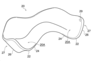
도 2에 도시하는 상악 의치상(20)은 저부(22), 내측 벽부(24) 및 외측 벽부(26)로 이루어지는 레진 등의 수지제의 치과 조형물이며, 보강 부재(28)가 일체적으로 형성되어 있다.The
도 2 중의 상악 의치상(20)은 수평면 상에 탑재되어 있고, 도 2 중의 중심 축선(B)은 구강 내에서 정중선과 중첩된다. 본 실시 형태에서는, 중심 축선(B)에 따른 입술측(도 2 중의 좌상측)을 「전측」이라 하고, 중심 축선(B)을 따른 인후측(도 2 중의 우하측)을 「안쪽측」이라 정의한다. 또한, 본 명세서에서는, 특별히 언급하지 않는 한, 상악 의치상(20)에 있어서의 「상측」 및 「하측」의 용어는, 도 2에 도시하는 바와 같이, 상악 의치상(20)을 상악 치조 융선에 감합한 상태에서의 상하 방향을 의미한다.The
또한, 상악 의치상(20)이 서로 감합되었을 때에 상악 치조 융선측에 위치하며, 오목부(20A)가 마련되어 있는 측의 표면을 「이면」이라 정의한다. 또한, 상악 의치상(20)이 감합되었을 때에 상악 치조 융선과 반대측에 위치하며, 도시하지 않은 인공치가 매립되는 복수 개의 함몰부(20B)(도 12a, 도 12b 참조)가 마련되어 있는 측의 표면을 「전면」이라 정의한다. 즉, 도 2는 상악 의치상(20)을 상측의 이면측으로부터 부감하여 본 사시도이다. 또한, 특별히 언급하지 않는 한, 상악 의치상(20)에 있어서의 「내측」의 용어는, 저부(22)의 이면을 정면으로부터 평면에서 본(도 12 참조) 상태에서, 저부(22)보다 중심 축선(B)에 가까운 쪽(혀측)을 의미하는 동시에, 「외측」의 용어는 저부(22)보다 중심 축선(B)으로부터 먼 측(협측)을 의미한다.In addition, when the
저부(22)는 평면에서 보아 편자 형상(즉, U자 형상)의 판 형상 부재이다. 내측 벽부(24)는 저부(22)의 U자의 내연 부분에, 저부(22)로부터 하수하도록 마련되어 있는 판 형상 부재이다. 또한, 외측 벽부(26)는 저부(22)의 U자의 외연 부분에, 저부(22)로부터 하수되도록 마련되어 있는 판 형상 부재이다.The
상악 의치상(20)은 저부(22), 내측 벽부(24) 및 외측 벽부(26)에 의해 둘러싸인, 편자 형상(즉, U자 형상)의 오목부(20A)를 가지며, 오목부(20A)에 상악 치조 융선이 끼워진다. 저부(22)의 이면은 상악 치조 융선의 하면을 덮는 부분이다. 내측 벽부(24)의 이면은 상악 치조 융선의 내측의 측벽면 및 구개 점막을 덮는 부분이다. 외측 벽부(26)의 이면은 상악 치조 융선의 협측 점막측의 측벽면을 덮는 부분이다.The
저부(22)에는 복수 개의 함몰부(20B)(도 12a, 도 12b 참조)가 전측으로부터 안쪽측을 걸쳐서 형성되어 있다. 함몰부(20B)의 개수는, 하악 의치상의 경우와 마찬가지로, 임의로 설정할 수 있다. 또한, 하악 의치상의 경우와 마찬가지로, 상악 의치상(20)에 있어서, 본체의 종단부(27)는 제 2 대구치의 함몰부보다 더욱 안쪽측의 영역의 단부이다.A plurality of
상악 의치상(20)의 보강 부재(28)는 오목부(20A)의 측벽부를 보강한다. 본 실시 형태에서는, 보강 부재(28)는 오목부(20A)의 좌우의 내측 벽부(24)의 이면의 상단끼리를 잇는 1개의 봉 형상 부재이다. 보강 부재(28)의 봉 형상 부재는 오목부(20A)의 좌우의 외측 벽부(26)의 구강 내의 안쪽측의 종단부(27)를 잇고, 중심 축선(A)과 교차하고 있다. 상악에 있어서의 「봉 형상 부재」의 의미는 하악의 경우와 마찬가지이다. 또한, 상악에 있어서의 보강 부재(28)는, 하악의 경우와 마찬가지로, 조형 후는 제거되는 것이지만, 봉형상의 것으로 한정되지 않으며, 오목부(20A)의 측벽부를 보강할 수 있으며, 제거 가능한 것이면, 예를 들면 판 형상, 아치 형상 등 다른 임의의 형상을 채용할 수 있다. 또한, 본 실시 형태에서는, 보강 부재(28)는 직선 형상의 1개의 봉 형상 부재이기 때문에, 간이하게 설계 및 제조가 가능하다. 또한, 보강 부재(28)의 개수도 1개 이상, 임의이다.The reinforcing
또한, 본 개시에서는, 보강 부재의 연결 위치는 적절히 변경할 수 있다. 또한, 내측 벽부(24) 및 외측 벽부(26)에 있어서, 중심 축선(B)을 따라서 안쪽측에 위치하는 종단부(27)는 오목부(20A)를 사이에 두고 인접하는 내측 벽부(24)와 외측 벽부(26)의 간격이 가장 크게 넓어지는 부위이기 때문에, 구조 특성상 조형시에 가장 변형되기 쉽다. 이 때문에, 보강 부재로서, 1개의 봉 형상 부재를 이용하는 경우, 보강 부재는 좌우의 안쪽측 종단부인 종단부(27)를 연결하는 것이 바람직하다.In addition, in this indication, the connection position of a reinforcing member can be changed suitably. Further, in the
또한, 상악 의치상(20)에서는, 외측 벽부(26)에 있어서의 상단의 위치는, 정상부(12)로부터, 상하 방향을 따라서 상측으로 가장 떨어지게 된다. 정상부(12)는 오목부(20A)를 사이에 두고 인접하는 내측 벽부(24)와 외측 벽부(26)를 잇고 있다. 이 때문에, 상단의 변형량은 특별히 커지므로, 보강 부재로서 1개의 봉 형상 부재를 이용하는 경우, 보강 부재는 좌우의 외측 벽부(26)의 상단을 연결하는 것이 바람직하다. 본 실시 형태에서는, 보강 부재(28)는 좌우의 외측 벽부(26)의 이면에서 안쪽측 종단부인 종단부(27)의 상단끼리를 이어서 연결하고 있다.In addition, in the
-치과 조형물의 제조 방법--Method of manufacturing dental implants-
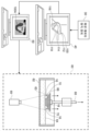
다음에, 본 실시 형태에 따른 치과 조형물의 제조 장치, 및 이 제조 장치를 이용한 치과 조형물의 제조 방법을 도 3 내지 도 8을 참조하여 설명한다. 본 실시 형태에 따른 치과 조형물의 제조 장치는, 도 3에 도시하는 바와 같이, 화상 데이터 취득 장치(30), 설계 화상 데이터 작성 장치(40), 제조 화상 데이터 작성 장치(50) 및 조형 장치(60)를 갖는다.Next, a manufacturing apparatus for a dental molding according to the present embodiment and a method for manufacturing a dental molding using the manufacturing apparatus will be described with reference to FIGS. 3 to 8 . As shown in FIG. 3 , the dental molding manufacturing device according to the present embodiment includes an image
(화상 데이터 취득 장치)(Image data acquisition device)
화상 데이터 취득 장치(30)는, 예를 들면 3D 스캐너이며, 설계 화상 데이터 작성 장치(40)에 접속되어 있다. 화상 데이터 취득 장치(30)는, 예를 들면 환자의 하악 치조 융선의 형상을 반영한 인상물(이하, 「하악 인상물(mandibular impression object)」이라 함), 또는 환자가 실제로 사용하고 있는, 보강 부재를 갖지 않는 하악 의치상을 스캔하고, 하악 의치상의 본체의 3차원 3D 형상을 나타내는 화상 데이터를 취득한다. 혹은, 환자의 구강 내로부터 직접 하악을 스캔하고, 하악 치조 융선의 3차원 3D 형상을 나타내는 화상 데이터를 취득한다. 취득된 화상 데이터는 설계 화상 데이터 작성 장치(40)에 입력된다. 또한, 본 개시에서는, 화상 데이터 취득 장치(30)는 필수는 아니며, 예를 들면 임의의 소프트웨어에 의해 작성되며, 미리 준비된 3D 형상 데이터가 설계 화상 데이터 작성 장치(40)에 입력되어도 좋다.The image
또한, 본 실시 형태에서는, 하악 치조 융선의 경우의 치과 조형물의 제조 방법이 예시적으로 설명되고 있지만, 본 개시에서는 이것으로 한정되지 않는다. 본 개시에서는, 하악 치조 융선의 경우와 마찬가지로, 상악 치조 융선 등의 편자 형상의 형상을 갖는 치과 조형물을 제조하는 경우여도, 예를 들면 환자의 상악 치조 융선의 형상을 반영한 인상물(즉, 상악 인상물), 실제로 사용하고 있는 상악 의치상 등의 편자 형상의 치과 조형물, 혹은 환자의 구강 내로부터 직접 스캔된 상악 치조 융선 등의 형상 등에 기초하여, 상악 의치상 등의 화상 데이터를 취득할 수 있다. 편자 형상의 치과 조형물은, 예를 들면 의치상, 마우스피스, 스프린트 등이다.In addition, in this embodiment, although the manufacturing method of the dental molding in the case of the mandibular alveolar ridge is illustratively demonstrated, this disclosure is not limited to this. In the present disclosure, as in the case of the mandibular alveolar ridge, even when a dental molding having a horseshoe-shaped shape such as the maxillary alveolar ridge is manufactured, for example, an impression reflecting the shape of the patient's maxillary alveolar ridge (ie, maxillary impression) image data of the maxillary denture base or the like can be acquired based on the shape of the maxillary alveolar ridge or the like directly scanned from the oral cavity of the patient, or a horseshoe-shaped dental molding such as the maxillary denture base in actual use. Horseshoe-shaped dental moldings are, for example, denture bases, mouthpieces, sprints, and the like.
(설계 화상 데이터 작성 장치)(Design image data creation device)
본 실시 형태의 설계 화상 데이터 작성 장치(40)로서는, 예를 들면 모두 도시하지 않은 중앙 집적 회로(CPU), 기억 장치, 입력 장치 및 표시 장치(즉, 출력 장치)를 구비한 범용적인 퍼스널 컴퓨터 등을 사용할 수 있다. 설계 화상 데이터 작성 장치(40)는 화상 데이터를 가공하기 위한 화상 처리 프로그램으로서, 3D-CAD 기능을 구비한다. 설계 화상 데이터 작성 장치(40)는 본 개시의 「화상 데이터 작성 장치」에 상당한다. 설계 화상 데이터 작성 장치(40)에는, 제조 화상 데이터 작성 장치(50)가 접속되어 있다.As the design image
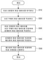
도 4에 도시하는 바와 같이, 설계 화상 데이터 작성 장치(40)는 화상 데이터 취득부(42A)와, 화상 데이터 작성부(42B)를 갖는 연산 장치(42)를 구비한다. 도 5 중의 단계(S10)에서, 화상 데이터 취득부(42A)는, 예를 들면 화상 데이터 취득 장치(30)로부터 하악 치조 융선, 하악 인상물 또는 하악 의치상의 본체의 화상 데이터를 취득한다. 화상 데이터 작성부(42B)는 3D-CAD 기능을 실행하는 영역이며, 화상 데이터 취득 장치(30)에서 취득한 하악 치조 융선, 하악 인상물 또는 하악 의치상의 본체의 화상 데이터를 실제의 치과 조형물로서의 사용에 적절한 형상으로 가공하여, 치과 조형물의 화상 데이터를 작성한다. 화상 데이터의 가공은, 예를 들면 스캔 직후의 스캔 화상 중에 포함되는 불필요한 부분의 형상의 삭제, 복수의 화상 데이터를 취득한 경우에 있어서의 화상 데이터의 통합 등이다.As shown in Fig. 4, the design image
또한, 도 5 중의 단계(S10)에서, 화상 데이터 취득 장치(30)로부터 취득한 하악 의치상의 본체의 화상 데이터를 이용하는 경우, 가공을 하지 않고 취득한 하악 의치상의 본체의 화상 데이터를 그대로 치과 조형물의 화상 데이터로서 사용하여도 좋다. 또한, 도 5 중의 단계(S20)에서, 화상 데이터 작성부(42B)는 보강 부재의 화상 데이터인 보강 부재 데이터(118)를 작성한다. 또한, 도 5 중의 단계(S30)에서, 화상 데이터 작성부(42B)는, 치과 조형물의 화상 데이터와 보강 부재 데이터(118)를, 1개의 하악 의치상의 형상을 나타내는 단일 데이터를 구성하는 데이터로서, 각각을 단일 데이터에 결합시키는 것에 의해 연결한다. 연결에 의해 설계용의 화상 데이터(100)가 작성된다.In addition, in the case of using the image data of the main body of the lower denture base acquired from the image
즉, 연결 후의 설계용의 화상 데이터(100)에서는, 치과 조형물의 화상 데이터와 보강 부재 데이터(118)가 일체화되어 있다. 예를 들면, 가상 3D 좌표 공간 내에서, 설계용의 화상 데이터(100)를 클릭 등을 하여 선택하면, 치과 조형물의 화상 데이터와 보강 부재 데이터(118)가 분리되는 일 없이, 치과 조형물의 화상 데이터와 보강 부재 데이터(118)를 일체적으로 이동시킬 수 있다.That is, in the
설계 화상 데이터 작성 장치(40)의 3D-CAD에 의해, 본 실시 형태에 따른 화상 데이터 작성 방법이 실시된다. 구체적으로는, 예를 들면 설계자는 치과 조형물의 화상 데이터를, 설계 화상 데이터 작성 장치(40)의 디스플레이 상에서, 가상 3D 좌표 공간 내에서의 임의의 위치에 이동, 배치 및 회전 가능하다. 또한, 보강 부재 데이터(118)의 형상을 1개 이상의 피처를 이용하여 작성하고, 작성한 보강 부재 데이터(118)를, 3D 좌표 공간 내에서, 치과 조형물의 화상 데이터 상에 이동시켜 중첩하고, 소정의 위치에서 서로를 연결할 수 있다.The image data creation method according to the present embodiment is implemented by 3D-CAD of the design image
여기에서, CAD는, CAM에 비해, 설계 작업에 있어서 유리하다. 예를 들면, 통상, CAD에서는 채용 가능한 피처의 종류가 CAM보다 많이 준비되어 있다. 또한, CAD에서는, CAM의 경우보다, 보강 부재 데이터(118)의 이동이나 회전 동작의 자유도가 높다. 또한, CAD에서는, 치과 조형물의 화상 데이터와 보강 부재 데이터(118)의 연결 상태를 유지한 채로, 치과 조형물의 화상 데이터 또는 보강 부재 데이터(118)의 형상을 부분적으로 변경하는 것도 용이하다. 이 때문에, CAD를 이용하는 것에 의해, 설계용의 화상 데이터(100)를 효율적으로, 정확하게 작성하는 것이 가능하게 된다.Here, compared to CAM, CAD is advantageous in design work. For example, CAD usually has more adoptable feature types than CAM. Further, in CAD, the degree of freedom of movement and rotation of the reinforcing
또한, 본 실시 형태에 따른 화상 데이터 작성 방법에서는, 도 5 중의 단계(S10) 및 단계(S20)의 처리를, 화상 데이터 취득 장치(30) 및 설계 화상 데이터 작성 장치(40)를 인간이 조작하여 실시하는 경우가 예시되었지만, 본 개시는 이것으로 한정되지 않는다. 예를 들면, 단계(S10) 및 단계(S20)의 처리를 컴퓨터에 실행시키는 화상 데이터 작성 프로그램을 작성하여도 좋다. 그리고, 작성한 화상 데이터 작성 프로그램에 의해 화상 데이터 취득 장치(30) 및 설계 화상 데이터 작성 장치(40)에 단계(S10) 및 단계(S20)의 처리를 실행시켜, 설계용의 화상 데이터(100)를 작성시켜도 좋다.Further, in the image data creation method according to the present embodiment, the process of step S10 and step S20 in FIG. 5 is performed by humans operating the image
또한, 단계(S10)에서의 치과 조형물의 화상 데이터의 취득은, 상술하는 바와 같이, 화상 데이터 취득 장치로 취득한 하악 치조 융선, 하악 인상물 또는 하악 의치상의 화상 데이터를 가공하는 것에 의해 취득하여도 좋다. 그러나, 본 개시에서는, 예를 들면 미리 존재하는 하악 의치상의 치과 조형물의 화상 데이터를 3D 스캐너 등에 판독하여 취득해도 좋다. 또한, 취득한 화상 데이터에 가공을 하는 일 없이, 그대로 보강 부재 데이터(118)와 연결하여, 설계용의 화상 데이터(100)를 작성하여도 좋다.In addition, the image data of the dental molding in step S10 may be acquired by processing the image data of the mandibular alveolar ridge, mandibular impression or mandibular denture base acquired with the image data acquisition device as described above. . However, in the present disclosure, image data of a pre-existing dental molding on a lower denture base may be acquired by reading it with a 3D scanner or the like, for example. Alternatively, the
도 3 중의 설계 화상 데이터 작성 장치(40)의 표시 장치의 내측에는, CAD로 작성된 하악 의치상의 설계용의 화상 데이터(100)가 예시되어 있다. 설계용의 화상 데이터(100)는, 가상 3D 좌표 공간 내에 있어서의 데이터 영역으로서, 실제의 하악 의치상의 정상부에 대응하는 정상부 영역(112)과, 내측 벽부에 대응하는 내측 벽부 영역(114)과, 외측 벽부에 대응하는 외측 벽부 영역(116)을 갖는다. 또한, 좌우의 내측 벽부 영역(114) 사이에는, 보강 부재 데이터(118)가 배치되어 있다. 설계용의 화상 데이터(100)는 제조 화상 데이터 작성 장치(50)에 입력된다.Inside the display device of the design image
(제조 화상 데이터 작성 장치)(Production Image Data Creation Device)
제조 화상 데이터 작성 장치(50)는, 설계 화상 데이터 작성 장치(40)와 마찬가지로, 모두 도시하지 않은 중앙 집적 회로, 기억 장치, 입출력 장치 등을 구비하는 컴퓨터이며, CAM 기능을 구비한다. 제조 화상 데이터 작성 장치(50)에는, 조형 장치(60)가 접속되어 있다. 도 5 중의 단계(S40)에서, 제조 화상 데이터 작성 장치(50)에 의해, 가상 3D 좌표 공간 내에서, 설계용의 화상 데이터(100)를 가공하여, 조형 장치(60)로 조형하기 위한, 제조용의 화상 데이터(100A)가 작성된다. 구체적으로는, 조형 장치(60)의 빌드 테이블에 대한 하악 의치상의 배치 각도나 거리 등의 조형 조건이 설정되며, 설정된 조형 조건은 CAM에 의해 제조용의 화상 데이터(100A)에 반영된다. 또한, CAM에 의해, 조형용의 서포트 핀의 데이터가 작성된다.Like the design image
도 6에 도시하는 바와 같이, CAM으로 가공된 제조용의 화상 데이터(100A)는, 가상 3D 좌표 공간 내에 있어서의 데이터 영역으로서 빌드 테이블에 대응하는 빌드 테이블 영역(166)에, 서포트 핀에 대응하는 복수 라인의 서포트 핀 영역(170)에 의해 매달려 있다. 복수 라인의 서포트 핀 영역(170)의 사이에는, 보강 부재 데이터(118)가 노출되어 있다. 제조용의 화상 데이터(100A)는 조형 장치(60)에 입력된다.As shown in FIG. 6 ,
(조형 장치)(Molding device)
도 3에 도시한 바와 같이, 조형 장치(60)는 매달림형 3D 프린터이며, 액조 광중합법에 의해 치과 조형물을 조형한다. 조형 장치(60)는 액상의 광경화성의 액체 수지(64)를 저장하는 액조(62)와, 치과 조형물의 토대가 되는 빌드 테이블(66)과, 빌드 테이블(66)을 매다는 매달림 부재(68)를 구비한다. 도 3 중에서 액조(62)의 하면에는, 빌드 테이블(66)의 하면에 광을 조사하는 광 조사기(69)가 마련되어 있다.As shown in FIG. 3, the
또한, 본 실시 형태의 조형 장치(60)는 매달림형이었지만, 본 개시에서는, 이것으로 한정되지 않는다. 또한, 본 실시 형태에서는, DLP(Digital Light Processing) 방식의 광조형이 예시되어 있었지만, 이것으로 한정되지 않으며, 예를 들면 SLA(Stereolithography) 방식의 광조형, LCD(Liquid Crystal Display) 방식의 광조형, 혹은 잉크젯 방식의 광조형 등 다른 조형 방식이 채용되어도 좋다.In addition, although the
광 조사기(69)는, 조형 장치(60)에 입력된 제조용의 화상 데이터(100A)에 기초하여, 액조(62) 내에 침지된 빌드 테이블(66)의 하측을 향하여, 자외선과 같은 소정의 파장의 광을 선택적으로 조사한다. 광 조사에 의해, 일정한 두께를 갖는 형성 영역(63)에서, 액체 수지(64)가 광중합되어 선택적으로 경화되고, 조형 대상물의 수지층이 형성된다. 그리고, 매달림 부재(68)가 도 1 중의 상측으로 이동하는 것에 의해, 빌드 테이블(66)이 설정된 수지층의 두께만큼 상승한다.The
광 조사기(69)를 이용하여 광이 선택적으로 조사되는 것에 의해, 선행하여 형성된 수지층 아래에, 후속의 수지층의 적층 상태가 형성된다. 도 3 중에는, 빌드 테이블(66)의 하면으로부터 연장되는 서포트 핀(70)에 의해, 조형되어 있는 하악 의치상(10)의 일부가 매달린 상태가 예시되어 있다. 도 5 중의 단계(S50)에서, 빌드 테이블(66)의 상승과 광의 조사가 반복되는 것에 의해, 도 1에 도시하는 바와 같이, 보강 부재(18)를 갖는 하악 의치상(10)이 최종적으로 조형된다.By selectively irradiating light using the
다음에, 조형된 하악 의치상(10)으로부터 보강 부재(18)를 절제하고, 본체의 연결 부분의 버어(burr) 등을 제거한다. 그리고, 하악 의치상(10)의 표면에 연마 등의 소정의 처리를 실시하는 것에 의해, 환자의 하악 치조 융선에 끼우는 것이 가능한, 본 실시 형태에 따른 치과 조형물로서의 하악 의치상을 얻을 수 있다. 도 7 중에는, 보강 부재(18)가 제거된 후, 오목부(10A)의 좌우의 내측 벽부(14)의 외면 상에 보강 부재(18)의 연결흔(19)이 형성된 하악 의치상(10)이 예시되어 있다. 또한, 도 8 중에는, 보강 부재(28)가 제거된 후, 오목부(20A)의 좌우의 외측 벽부(26)의 내면 상에 보강 부재(28)의 연결흔(29)이 형성된 상악 의치상(20)이 예시되어 있다.Next, the reinforcing
또한, 본 개시에서는, 연결흔은 실제로 치조 융선에 감합된 상태의 의치상의 표면 상에 그대로 남아 있어도 좋으며, 혹은 표면 처리가 실시되는 것에 의해 눈에 띄지 않게 되어 있어도 좋다. 표면 상에 남아 나타나는 연결흔의 형상은 보강 부재의 연결 부분의 형상에 따라서 임의이다. 또한, 의치상의 표면 상에 연결흔이 눈에 띄지 않는 경우, 예를 들면 수 미크론 정도 표면을 박리하고, 박리 부분을 현미경으로 수지를 관찰했을 때, 보강 부재의 연결 부분의 수지와, 연결 부분의 주위의 수지의 성상(properties)의 차이에 기초하여, 보강 부재가 마련되어 있었는지의 여부를 판단할 수 있다.In addition, in the present disclosure, the joint scar may remain as it is on the surface of the denture base in a state actually fitted to the alveolar ridge, or may be made inconspicuous by surface treatment. The shape of the connection mark remaining on the surface is arbitrary depending on the shape of the connection portion of the reinforcing member. In addition, when the connection mark is not conspicuous on the surface of the denture base, for example, when the surface is peeled off about several microns and the resin is observed under a microscope at the peeled part, the resin of the connection part of the reinforcing member and the connection part Based on the difference in the properties of the surrounding resin, it can be judged whether or not the reinforcing member is provided.
또한, 하악 의치상(10)에서는, 내측 벽부(14) 및 외측 벽부(16)에서 변형되기 쉬운 안쪽측 종단부인 종단부(17)가 연결되는 것이 바람직하기 때문에, 연결흔은 좌우의 종단부(17)에 형성되어 있는 것이 바람직하다. 또한, 내측 벽부(14) 및 외측 벽부(16)에 있어서의 하단은 변형량이 커지는 영역이기 때문에, 연결흔은 좌우의 내측 벽부(14)의 하단에 형성되어 있는 것이 바람직하다. 본 실시 형태에서는, 연결흔(19)은 좌우의 내측 벽부(14)의 전면 이면에 있어서 종단부(17)의 하단에 형성되어 있다.In addition, in the
또한, 상악 의치상(20)에서는, 내측 벽부(24) 및 외측 벽부(26)에 있어서 변형되기 쉬운 안쪽측 종단부인 종단부(27)가 연결되는 것이 바람직하기 때문에, 연결흔은 종단부(27)에 형성되어 있는 것이 바람직하다. 또한, 내측 벽부(24) 및 외측 벽부(26)에 있어서의 상단은 변형량이 커지는 영역이기 때문에, 연결흔은 좌우의 외측 벽부(26)의 상단에 형성되어 있는 것이 바람직하다. 본 실시 형태에서는, 연결흔(29)은 좌우의 외측 벽부(26)의 이면에 있어서 종단부(27)의 상단에 형성되어 있다.In addition, in the
실시예Example
도 9a 내지 도 9f에 도시하는 바와 같이, 본 발명자들은 본 실시 형태에 따른 화상 데이터 작성 방법을 이용하여 조형한 6개의 하악 의치상(10)을 각각 제 1 실시예 내지 제 6 실시예로서 준비했다. 제 1 실시예 내지 제 6 실시예의 하악 의치상(10)의 보강 부재(18)의 연결 위치는 각각 상이하다. 도 9a 내지 도 9f 중, 상측에는, 하악 의치상(10)의 평면으로부터 본 상태가 예시되어 있는 동시에, 하측에는, 하악 의치상(10)을 중심 축선(A)을 따라서 안쪽측으로부터 전측을 향하여 본 경우의 측면으로부터 본 상태가 예시되어 있다.As shown in FIGS. 9A to 9F , the present inventors prepared six
도 9a에 도시하는 바와 같이, 제 1 실시예의 보강 부재(18)는, 하악 의치상(10)의 좌우의 내측 벽부의 사이에서, 안쪽측의 종단부의 상부에 연결되어 있는 직선 형상의 봉 형상 부재이다. 또한, 도 9b에 도시하는 바와 같이, 제 2 실시예의 보강 부재(18)는 하악 의치상(10)의 좌우의 내측 벽부의 사이에서, 안쪽측의 종단부의 상부에 연결되어 있는 U자 형상의 봉 형상 부재이다. 또한, 도 9c에 도시하는 바와 같이, 제 3 실시예의 보강 부재(18)는 하악 의치상(10)의 좌우의 내측 벽부의 사이에서, 안쪽측의 종단부의 하부에 연결되어 있는 직선 형상의 봉 형상 부재이다.As shown in FIG. 9A , the reinforcing
또한, 도 9d에 도시하는 바와 같이, 제 4 실시예의 보강 부재(18)는, 하악 의치상(10)의 좌우의 내측 벽부의 사이에서, 전측의 제 1 소구치의 함몰부(10A)의 위치의 상부에 연결되어 있는 직선 형상의 봉 형상 부재이다. 또한, 도 9e에 도시하는 바와 같이, 제 5 실시예의 보강 부재(18)는, 하악 의치상(10)의 좌우의 내측 벽부의 사이에서, 전측의 제 1 소구치의 함몰부(10A)의 위치의 하부에 연결되어 있는 직선 형상의 봉 형상 부재이다. 또한, 도 9f에 도시하는 바와 같이, 제 6 실시예의 보강 부재(18)는, 하악 의치상(10)의 좌우의 내측 벽부의 사이에서, 안쪽측의 제 1 대구치의 함몰부(10A)의 위치의 하부에 연결되어 있는 직선 형상의 봉 형상 부재이다.Further, as shown in FIG. 9D , the reinforcing
또한, 본 발명자들은 보강 부재를 갖지 않는 본체만으로 이루어지는 제 1 비교예에 따른 하악 의치상을 조형했다. 제 1 비교예에 따른 하악 의치상의 본체의 형상은 제 1 실시예 내지 제 6 실시예의 하악 의치상(10)의 본체의 형상과 동일하다.In addition, the present inventors molded a lower denture base according to Comparative Example 1 consisting only of a main body without a reinforcing member. The shape of the body of the lower denture base according to the first comparative example is the same as that of the body of the
본 실시예에서는, 조형에 앞서, 제 1 실시예 내지 제 6 실시예, 및 제 1 비교예의 각각의 설계용의 화상 데이터(100)의 작성을 실행하기 위해, 3D Systems사제 「Geomagic design X」가 설계 화상 데이터 작성 장치의 3D-CAD로서 채용되었다. 그리고, 작성된 설계용의 화상 데이터(100)는 제조 화상 데이터 작성 장치의 CAM으로서의 Kulzer사제 「cara CAM 2.0」에 입력되고, 빌드 테이블 영역에 대해 소정의 각도로 배치되었다. 그리고, CAM에 의해, 배치된 화상 데이터에 대해 빌드 테이블 영역으로부터 수직으로 서포트 핀 영역을 연장하고 지지시킨 후, 복수 매의 연속된 슬라이스 데이터의 제조용의 화상 데이터(100A)를 작성했다.In this embodiment, in order to create the
그리고, 제조용의 화상 데이터(100A)를 조형 장치로서의 Kulzer사제 3D 프린터 「cara Print 4.0」에 전송하여, 조형을 실행했다. 조형에 사용한 3D 프린터용 잉크는 Kulzer사제 「dima Print Denture Base」를 사용했다. 그리고, 조형에 의해 얻어진 하악 의치상을 세정하고, 서포트 핀을 절제한 후, 포스트 큐어를 실시했다. 포스트 큐어에 사용한 장치는 Kulzer사제 「HiLite power 3D」였다. 그리고, 포스트 큐어 후의 의치상을, 3Shape사제 3D 스캐너 「E3」을 이용하여, 의치(인공치)측의 전면, 및 치조 융선(점막)측의 이면의 각각의 3D 화상 데이터를 캡쳐했다. 그리고, 캡쳐된 3D 화상 데이터를 3D Systems사제 리버스 엔지니어링 소프트웨어 「Geomagic design X」에 입력하고, 설계용의 화상 데이터(100)와 중첩하고, 편차 계산을 실시하여 매칭 스코어를 산출했다.Then, the
매칭 스코어는, 제 1 실시예 내지 제 6 실시예 및 제 1 비교예에 대해 각각 캡쳐된 조형 후의 3D 화상 데이터와, 조형 전에 작성된 설계용의 화상 데이터(100) 사이에 있어서의, 변위에 대한 평가를 나타낸다. 구체적으로는, 조형 후의 3D 화상 데이터와 조형 전의 설계용의 화상 데이터(100) 사이에서 서로 대응하는 표면의 위치의 좌표에 대해 변위(즉, 차분)가 산출된다. 그리고, 산출된 변위가 2개의 데이터의 사이에서 플러스(+)/마이너스(-) 200㎛ 이하인 부분의 비율이 매칭 스코어로서 산출된다. 매칭 스코어의 수치가 높을수록, 조형 정밀도가 높아진다.The matching score is an evaluation of the displacement between the 3D image data after molding captured for each of the first to sixth examples and the first comparative example, and the
도 10에 도시하는 바와 같이, 보강 부재를 갖지 않는 제 1 비교예의 경우, 전면측의 매칭 스코어는 70인 동시에, 이면측의 매칭 스코어는 80이었다. 제 1 비교예의 매칭 스코어는, 대비한 하악 의치상 중에서, 전면측 및 이면측의 모두에 있어서도 가장 낮았다. 도 11a 중에는, 제 1 비교예의 설계용의 화상 데이터(100Z)의 전면측에, 변위에 따라서 패터닝된 3개의 영역이 중첩되어 예시되어 있다. 또한, 도 11b 중에는, 제 1 비교예의 설계용의 화상 데이터(100Z)의 이면측에, 변위에 따라서 패터닝된 3개의 영역이 중첩되어 예시되어 있다.As shown in Fig. 10, in the case of Comparative Example 1 having no reinforcing member, the matching score on the front side was 70 and the matching score on the back side was 80. The matching score of Comparative Example 1 was the lowest among the prepared lower denture bases also on both the front side and the back side. In Fig. 11A, three regions patterned according to the displacement are overlapped on the front side of the
예를 들면, 도 11a 중에서 전면측에서, 실선의 사선 패턴이 부여된 좌우의 외측 벽부(16)의 영역에서는, 0.1㎛ 이상, 외측 벽부(16)의 상측(즉, 도 11a의 지면을 수직으로 관통하는 상하 방향에 있어서 상측)을 향하는 변위가 생겼다. 또한, 도 11b 중에서 이면측에서, 점선의 사선 패턴이 부여된 좌우의 외측 벽부(16)의 영역에서는, 0.1㎛ 이상, 외측 벽부(16)의 하측(즉, 도 11b의 지면을 수직으로 관통하는 상하 방향에 있어서 하측)을 향하는 변위가 생겼다. 또한, 도 11a 및 도 11b 중에서, 실선의 사선 패턴 또는 점선의 사선 패턴이 부여되어 있지 않은 백색의 영역은 생긴 변위가 0.1㎛ 미만의 부분이다. 도 11a 및 도 11b로부터, 보강 부재를 갖지 않는 제 1 비교예에 따른 하악 의치상의 경우, 후구치패드를 포함하는, 안쪽측의 내측 벽부(14) 및 외측 벽부(16)의 변위가 특히 큰 것을 알 수 있다.For example, in FIG. 11A, in the area of the left and right
한편, 도 10에 도시하는 바와 같이, 제 1 실시예 내지 제 6 실시예의 매칭 스코어는 전면측에서는 72 이상, 이면측에서는 81 이상으로, 모두 제 1 비교예보다 높았다. 특히, 도 9c에 도시한 직선 형상의 봉 형상 부재의 보강 부재(18)가 좌우의 내측 벽부의 사이에서 안쪽측의 종단부의 하부에 연결되어 있는 제 3 실시예의 매칭 스코어는 전면측에서 95, 이면측에서 97로, 대비한 하악 의치상 중에서 가장 높았다.On the other hand, as shown in Fig. 10, the matching scores of the first to sixth examples were 72 or more on the front side and 81 or more on the back side, both of which were higher than those of the first comparative example. In particular, the matching score of the third embodiment in which the reinforcing
또한, 도 12a 및 도 12b에 도시하는 바와 같이, 본 발명자들은 본 실시 형태에 따른 화상 데이터 작성 방법을 이용하여 2개의 상악 의치상(20)을 조형하고, 각각을 제 7 실시예 및 제 8 실시예로 하여 준비했다. 제 7 실시예 및 제 8 실시예의 상악 의치상(20)의 보강 부재(28)의 연결 위치는 각각 상이하다.Further, as shown in FIGS. 12A and 12B, the present inventors molded two
도 12a에 도시하는 바와 같이, 제 7 실시예의 보강 부재(28)는 상악 의치상(20)의 좌우의 외측 벽부의 사이에서 안쪽측의 종단부(27)의 상부에 연결되어 있는 직선 형상의 봉 형상 부재이다. 또한, 도 12b에 도시하는 바와 같이, 제 8 실시예에서는, 제 7 실시예와 마찬가지의 직선 형상의 봉 형상 부재의 보강 부재(28)에 부가하여, 좌우의 내측 벽부를 잇는 봉 형상 부재의 보강 부재(28)가 더 마련되어 있다. 제 8 실시예에 있어서의 외측 벽부의 사이의 보강 부재(28)와 내측 벽부의 사이의 보강 부재(28)는 거의 동일 직경이며, 상하 방향에 있어서 거의 중첩되는 위치에 배치되어 있다.As shown in FIG. 12A, the reinforcing
또한, 본 발명자들은 하악 의치상의 경우와 마찬가지로, 보강 부재를 갖지 않는 제 2 비교예에 따른 상악 의치상을 조형했다. 제 2 비교예에 따른 상악 의치상의 형상은 보강 부재 이외, 제 7 실시예 및 제 8 실시예의 상악 의치상(20)의 형상과 동일하다. 그리고, 조형에 앞서서, 하악 의치상의 경우와 마찬가지의 조건으로, 제 7 실시예, 제 8 실시예 및 제 2 비교예의 각각의 설계용의 화상 데이터(200)를 작성하고, 작성된 설계용의 화상 데이터(200)를 이용하여 제조용의 화상 데이터(200A)를 작성했다. 그리고, 각각의 제조용의 화상 데이터(200A)에 기초하여, 상악 의치상을 조형했다.Further, the present inventors molded an upper denture base according to Comparative Example 2 having no reinforcing member, similarly to the case of the lower denture base. The shape of the upper denture base according to Comparative Example 2 is the same as the shape of the
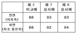
도 13에 도시하는 바와 같이, 보강 부재를 갖지 않는 제 2 비교예의 경우, 전면측의 매칭 스코어는 88이며, 이면측의 매칭 스코어는 88이었다. 대비한 상악 의치상 중에서, 제 2 비교예의 매칭 스코어의 값은 모두 가장 낮았다.As shown in Fig. 13, in the case of the second comparative example having no reinforcing member, the matching score on the front side was 88, and the matching score on the back side was 88. Among the compared maxillary denture bases, all the values of the matching scores of Comparative Example 2 were the lowest.
또한, 제 7 실시예의 매칭 스코어 및 제 8 실시예의 매칭 스코어는 전면측에서는 모두 93이었다. 또한, 이면측에서는, 제 7 실시예의 매칭 스코어는 92인 한편, 제 8 실시예의 매칭 스코어는 94였다. 제 8 실시예와 같이, 상악 의치상(20)의 좌우의 외측 벽부의 사이와 좌우의 내측 벽부의 사이의 양쪽에 보강 부재(28)가 마련되어 있는 경우의 쪽이, 좌우의 외측 벽부의 사이에만 보강 부재(28)가 마련되어 있는 경우보다, 매칭 스코어가 높아진다.Further, both the matching score of the seventh embodiment and the matching score of the eighth embodiment were 93 on the front side. Further, on the back side, the matching score of the seventh embodiment was 92, whereas the matching score of the eighth embodiment was 94. As in the eighth embodiment, in the case where the reinforcing
(작용 효과)(action effect)
본 실시 형태에 따른 치과 조형물의 화상 데이터 작성 방법에서는, 의치상의 설계용의 화상 데이터(100, 200)를 작성할 때에, 오목부의 측벽부를 보강하는 보강 부재(18, 28)의 화상 데이터인 보강 부재 데이터(118, 128)도 CAD로 작성된다. 이 때문에, CAM측에서 보강 부재 데이터(118, 128)를 작성하는 것보다도 적절한 위치에 보강 부재가 배치되므로, 3D 프린터로 조형되는 의치상의 변형을 최소한으로 억제할 수 있으며, 설계용의 화상 데이터(100, 200)에 따른 의치상을 조형할 수 있다. 따라서, 조형 정밀도가 양호하고, 조형 정밀도의 안정성이 뛰어나며, 또한 간편하게 보강 부재 데이터(118, 128)를 형성할 수 있다.In the image data creation method of the dental molding according to the present embodiment, when creating
또한, 본 실시 형태에서는, 보강 부재(18, 28)가 오목부(10A, 20A)의 좌우의 측벽부를 잇는 1개의 봉 형상 부재이기 때문에, 보강 부재(18, 28)를 간단하고 쉬운 구조로 할 수 있다.Further, in the present embodiment, since the reinforcing
또한, 본 실시 형태에서는, 하악 의치상(10)의 보강 부재(18)의 봉 형상 부재는 좌우의 내측 벽부(14)의 전면의 안쪽측 종단부인 종단부(17)를 잇고 있다. 또한, 상악 의치상(20)의 보강 부재(28)의 봉 형상 부재는 좌우의 외측 벽부(26)의 이면의 안쪽측 종단부인 종단부(27)를 잇고 있다. 구조 특성상 가장 변형하기 쉬운 좌우의 측벽부의 안쪽측 종단부인 종단부(17, 27)를 봉 형상 부재로 잇는 것에 의해, 변형을 억제하여 조형 정밀도를 보다 높일 수 있다.Moreover, in this embodiment, the rod-shaped member of the reinforcing
또한, 본 실시 형태에서는, 하악 의치상(10)의 보강 부재(18)로서의 봉 형상 부재가 좌우의 내측 벽부(14) 중에서도 특히 변형량이 큰 하단끼리를 잇고 있기 때문에, 하악 의치상(10)의 조형 정밀도를 한층 높일 수 있다.In addition, in this embodiment, since the rod-shaped member as the reinforcing
또한, 본 실시 형태에서는, 상악 의치상(20)의 보강 부재(28)의 봉 형상 부재가, 좌우의 외측 벽부(26) 중에서도 특히 변형량이 큰 상단끼리를 잇고 있기 때문에, 상악 의치상(20)의 조형 정밀도를 한층 높일 수 있다.In addition, in this embodiment, since the rod-shaped member of the reinforcing
또한, 본 실시 형태에서는, 상악 의치상(20)의 보강 부재(28)는 상악 의치상(20)에 있어서의 오목부(20A)의 좌우의 내측 벽부(24)의 전면끼리를 잇는 봉 형상 부재를 더 갖는다. 이 때문에, 상악 의치상(20)의 조형 정밀도를 한층 높일 수 있다.In addition, in this embodiment, the reinforcing
또한, 본 실시 형태에 따른 치과 조형물의 제조 방법에서는, 조형 공정에 있어서, 조형 중에 변형되기 쉬운 부분이 보강 부재(18, 28)에 의해 보강되므로, 양호하고 안정된 조형 정밀도로 치과 조형물을 제조할 수 있다. 특히, 본 실시 형태에서는, 치과 조형물은 환자의 치조 융선에 끼워지는 하악 의치상(10) 및 상악 의치상(20)이다. 의치상의 조형 정밀도가 높아지는 것에 의해, 환자의 하악 의치상(10) 및 상악 의치상(20)의 장착감을 높일 수 있다.In addition, in the manufacturing method of the dental molding according to the present embodiment, in the molding process, since the parts easily deformed during molding are reinforced by the reinforcing
또한, 본 실시 형태에 따른 치과 조형물의 화상 데이터 작성 방법을 컴퓨터에 실행시켜도, 조형 정밀도가 양호하며, 조형 정밀도의 안정성이 뛰어나고, 또한 간편하게 의치상을 보강하는 보강 부재의 화상 데이터를 형성할 수 있다.In addition, even if the image data creation method of the dental molding according to the present embodiment is executed on a computer, the molding accuracy is good, the stability of the molding accuracy is excellent, and the image data of the reinforcing member for reinforcing the denture base can be easily formed.
<그 외의 실시 형태><Other embodiments>
본 개시는 하기의 개시한 실시 형태에 의해 설명했지만, 이 개시의 일부를 이루는 논술 및 도면은 본 개시를 한정하는 것으로 이해해서는 안된다. 본 개시로부터 당업자에게는 여러 가지 대체 실시 형태, 실시예 및 운용 기술이 명확해진다고 고려되어야 한다. 예를 들면, 본 실시 형태에서는, CAD 기능을 갖는 설계 화상 데이터 작성 장치(40)와 CAM 기능을 갖는 제조 화상 데이터 작성 장치(50)는 서로 다른 장치로서 예시되었지만, 본 개시에서는 일체적으로 구성되어도 좋다.Although the present disclosure has been described by the following disclosed embodiments, the discussion and drawings forming a part of this disclosure should not be construed as limiting the present disclosure. It should be considered that various alternative embodiments, examples, and operation techniques will become clear to those skilled in the art from this disclosure. For example, in the present embodiment, the design image
또한, 예를 들면, 본 실시 형태에서는, 설계 화상 데이터 작성 장치(40)가 연산 장치(42)를 가지며, 연산 장치(42)에 의해 화상 데이터 작성 방법이 실행되는 경우가 예시되었지만, 본 개시에서는, 이것으로 한정되지 않는다. 본 개시에서는, 설계 화상 데이터 작성 장치와는 별도로, 화상 데이터 작성 방법을 실행하는 연산 장치를 갖는 컴퓨터로서의 서버가 마련되며, 서버를 중심으로 하는, 치과 조형물의 화상 데이터 작성 시스템 또는 치과 조형물의 제조 시스템이 구성되어도 좋다. 서버는 화상 데이터 취득 장치, 설계 화상 데이터 작성 장치, 제조 화상 데이터 작성 장치 및 조형 장치의 모두에 접속될 수 있는 동시에, 각각의 동작을 제어할 수 있다. 치과 조형물의 화상 데이터 작성 시스템 또는 치과 조형물의 제조 시스템을 구축하는 것에 의해, 치과 조형물의 화상 데이터 작성, 및 치과 조형물의 제조에 따른 일련의 작업 효율을 높이는 것이 가능하게 되는 동시에, 각각의 설비를 효율적으로 가동시키는 것이 가능하게 된다.In addition, for example, in this embodiment, the case where the design image
또한, 도 1 내지 도 13 중에 예시한 구성을 부분적으로 조합하여, 본 개시를 구성할 수도 있다. 이상과 같이, 본 개시는 상기에 기재하고 있지 않은 여러 가지 실시 형태 등을 포함하는 동시에, 본 개시의 기술적 범위는 상기의 설명으로부터 타당한 특허 청구의 범위의 발명 특정 사항에 의해서만 정해지는 것이다.In addition, the present disclosure may be configured by partially combining the configurations illustrated in FIGS. 1 to 13 . As described above, the present disclosure includes various embodiments not described above, and the technical scope of the present disclosure is determined only by the invention-specific matter of the appropriate claims from the above description.
2020년 8월 31일에 출원된 일본 특허 출원 제 2020-146114 호의 개시는 그 전체가 참조에 의해 본 명세서에 포함된다. 본 명세서에 기재된 전체 문헌, 특허 출원, 및 기술 규격은 각각의 문헌, 특허 출원, 및 기술 규격이 참조에 의해 포함되는 것이 구체적이며, 또한 각각에 기록된 경우와 동일한 정도로, 본 명세서 내에 참조에 의해 포함된다.The disclosure of Japanese Patent Application No. 2020-146114 filed on August 31, 2020 is incorporated herein by reference in its entirety. All documents, patent applications, and technical specifications described herein are specifically incorporated by reference, and are incorporated by reference within this specification to the same extent as if each document, patent application, and technical specification was incorporated by reference. included
10: 하악 의치상
10A: 오목부
10B: 함몰부
12: 정상부
14: 내측 벽부
16: 외측 벽부
17: 종단부
18: 보강 부재
19: 연결흔
20: 상악 의치상
20A: 오목부
20B: 함몰부
22: 저부
24: 내측 벽부
26: 외측 벽부
27: 종단부
28: 보강 부재
29: 연결흔
30: 화상 데이터 취득 장치
40: 설계 화상 데이터 작성 장치
42: 연산 장치
42A: 화상 데이터 취득부
42B: 화상 데이터 작성부
50: 제조 화상 데이터 작성 장치
60: 조형 장치
62: 액조
63: 형성 영역
64: 액체 수지
66: 빌드 테이블
68: 매달림 부재
69: 광 조사기
70: 서포트 핀
100, 100Z: 설계용의 화상 데이터
100A: 제조용의 화상 데이터
112: 정상부 영역
114: 내측 벽부 영역
116: 외측 벽부 영역
118: 보강 부재 데이터
160: 서포트 핀 데이터
166: 빌드 테이블 영역
200: 설계용의 화상 데이터10:
10B: depression 12: top
14: inner wall 16: outer wall
17: end portion 18: reinforcing member
19: connection scar 20: maxillary denture base
20A:
22: bottom part 24: inner wall part
26: outer wall portion 27: end portion
28: reinforcing member 29: connection mark
30: image data acquisition device 40: design image data creation device
42:
42B image
60: molding device 62: liquid tank
63
66: build table 68: hanging member
69: light irradiator 70: support pin
100, 100Z: image data for
112
116: outer wall area 118: reinforcing member data
160: support pin data 166: build table area
200: image data for design
Claims (13)
CAD로 상기 측벽부를 보강하는 보강 부재의 화상 데이터를 작성하는 공정과,
상기 치과 조형물의 화상 데이터와 상기 보강 부재의 화상 데이터를 연결하는 공정을 갖는
치과 조형물의 화상 데이터 작성 방법.Acquiring image data of a dental molding having a side wall portion forming a horseshoe-shaped concave portion;
A step of creating image data of a reinforcing member for reinforcing the side wall portion with CAD;
and a step of linking image data of the dental molding and image data of the reinforcing member.
A method for creating image data of dental implants.
상기 보강 부재는 좌우의 상기 측벽부를 잇는 1개의 봉 형상 부재를 갖는
치과 조형물의 화상 데이터 작성 방법.According to claim 1,
The reinforcing member has one rod-shaped member connecting the side wall portions on the left and right.
A method for creating image data of dental implants.
상기 봉 형상 부재는 좌우의 상기 측벽부의 구강 내의 안쪽측 종단부를 잇고 있는
치과 조형물의 화상 데이터 작성 방법.According to claim 2,
The rod-shaped member connects the inner end of the oral cavity of the left and right side walls
A method for creating image data of dental implants.
상기 보강 부재는 하악의 치과 조형물에 있어서의 좌우의 내측 벽부의 전면을 잇는 봉 형상 부재를 갖는
치과 조형물의 화상 데이터 작성 방법.According to claim 2 or 3,
The reinforcing member has a rod-shaped member connecting the front surfaces of the left and right inner wall portions in the lower dental sculpture.
A method for creating image data of dental implants.
상기 봉 형상 부재는 좌우의 상기 내측 벽부의 하단끼리를 잇고 있는
치과 조형물의 화상 데이터 작성 방법.According to claim 4,
The rod-shaped member connects the lower ends of the inner wall portions on the left and right
A method for creating image data of dental implants.
상기 보강 부재는 상악의 치과 조형물에 있어서의 좌우의 외측 벽부의 이면을 잇는 봉 형상 부재를 갖는
치과 조형물의 화상 데이터 작성 방법.According to claim 2 or 3,
The reinforcing member has a rod-shaped member connecting the back surface of the left and right outer wall portions in the maxillary dental molding
A method for creating image data of dental implants.
상기 봉 형상 부재는 좌우의 상기 외측 벽부의 상단끼리를 잇고 있는
치과 조형물의 화상 데이터 작성 방법.According to claim 6,
The rod-shaped member connects the upper ends of the outer wall portions on the left and right
A method for creating image data of dental implants.
상기 보강 부재는 상악의 치과 조형물에 있어서의 좌우의 내측 벽부의 전면을 잇는 봉 형상 부재를 더 갖는
치과 조형물의 화상 데이터 작성 방법.According to claim 6 or 7,
The reinforcing member further has a rod-shaped member connecting the front surfaces of the left and right inner wall portions in the maxillary dental molding.
A method for creating image data of dental implants.
상기 치과 조형물은 환자의 치조 융선(alveolar ridge)에 끼워지는 의치상(denture base)인
치과 조형물의 화상 데이터 작성 방법.According to any one of claims 1 to 8,
The dental sculpture is a denture base fitted to the patient's alveolar ridge.
A method for creating image data of dental implants.
상기 설계용의 화상 데이터를 이용하여 제조용의 화상 데이터를 작성하는 공정과,
상기 제조용의 화상 데이터를 이용하여 치과 조형물을 3D 프린터로 조형하는 공정을 포함하는
치과 조형물의 제조 방법.A step of creating CAD image data for design of a dental molding in which a reinforcing member is formed by the method for creating image data of a dental molding according to any one of claims 1 to 9;
a step of creating image data for manufacturing using the image data for design;
Including a step of modeling a dental sculpture with a 3D printer using the image data for manufacturing
A method for manufacturing dental implants.
치과 조형물.In the dental molding having a side wall portion forming a horseshoe-shaped concave portion, the left and right side wall portions have connection marks of reinforcing members reinforcing the side wall portion at the inner longitudinal end of the oral cavity.
dental implants.
CAD로 상기 측벽부를 보강하는 보강 부재의 화상 데이터를 작성하고, 상기 치과 조형물의 화상 데이터와 상기 보강 부재의 화상 데이터를 연결하는 화상 데이터 작성부를 갖는
연산 장치를 구비하는
치과 조형물의 화상 데이터 작성 장치.An image data acquisition unit for acquiring image data of a dental molding having a side wall portion forming a horseshoe-shaped concave portion;
An image data creation unit for creating image data of a reinforcing member reinforcing the side wall portion with CAD, and linking the image data of the dental molding and the image data of the reinforcing member.
equipped with an arithmetic device
An image data creation device for dental implants.
화상 데이터 작성부에, CAD로 상기 측벽부를 보강하는 보강 부재의 화상 데이터를 작성시키고, 상기 치과 조형물의 화상 데이터에 상기 보강 부재의 화상 데이터를 연결하는 단계를 포함하는
처리를 컴퓨터에 실행시키는
치과 조형물의 화상 데이터 작성 프로그램.Acquiring image data of a dental molding having a side wall portion forming a horseshoe-shaped concave portion in an image data acquisition unit;
In an image data creation unit, creating image data of a reinforcing member for reinforcing the side wall portion with CAD, and linking the image data of the reinforcing member to the image data of the dental molding.
run the process on the computer
An image data creation program for dental implants.
Applications Claiming Priority (3)
| Application Number | Priority Date | Filing Date | Title |
|---|---|---|---|
| JPJP-P-2020-146114 | 2020-08-31 | ||
| JP2020146114 | 2020-08-31 | ||
| PCT/JP2021/030231 WO2022044929A1 (en) | 2020-08-31 | 2021-08-18 | Method for creating image data of dental molded article, device for creating image data of dental molded article, program for creating image data of dental molded article, method for manufacturing dental molded article, and dental molded article |
Publications (1)
| Publication Number | Publication Date |
|---|---|
| KR20230050428A true KR20230050428A (en) | 2023-04-14 |
Family
ID=80354244
Family Applications (1)
| Application Number | Title | Priority Date | Filing Date |
|---|---|---|---|
| KR1020237008652A KR20230050428A (en) | 2020-08-31 | 2021-08-18 | Image data creation method of dental sculpture, image data creation device of dental sculpture, image data creation program of dental sculpture, manufacturing method of dental sculpture, and dental sculpture |
Country Status (5)
| Country | Link |
|---|---|
| US (1) | US20230301759A1 (en) |
| EP (1) | EP4205696A4 (en) |
| JP (1) | JP7524329B2 (en) |
| KR (1) | KR20230050428A (en) |
| WO (1) | WO2022044929A1 (en) |
Citations (1)
| Publication number | Priority date | Publication date | Assignee | Title |
|---|---|---|---|---|
| WO2010058822A1 (en) | 2008-11-20 | 2010-05-27 | 国立大学法人東京医科歯科大学 | Plate denture and process for producing same |
Family Cites Families (13)
| Publication number | Priority date | Publication date | Assignee | Title |
|---|---|---|---|---|
| ES2702779T3 (en) * | 2007-06-07 | 2019-03-05 | Nobel Biocare Services Ag | Procedure and sintered product to form a dental bridge |
| US8535580B2 (en) * | 2007-09-27 | 2013-09-17 | 3M Innovative Properties Company | Digitally forming a dental model for fabricating orthodontic laboratory appliances |
| EP3598294B1 (en) * | 2012-05-10 | 2021-09-29 | Renishaw PLC | Method of manufacturing an article |
| JP6280102B2 (en) * | 2012-05-10 | 2018-02-14 | レニショウ パブリック リミテッド カンパニーRenishaw Public Limited Company | Method for manufacturing an article |
| JP6296983B2 (en) * | 2012-08-08 | 2018-03-20 | 有限会社 ディーシーエル タニモト | Temporary denture base or temporary partial denture preparation device, and provisional denture base or temporary partial denture base preparation method |
| DE102014113148A1 (en) * | 2014-09-12 | 2016-03-31 | Amann Girrbach Ag | sintered blank |
| US10449016B2 (en) * | 2014-09-19 | 2019-10-22 | Align Technology, Inc. | Arch adjustment appliance |
| US20180304541A1 (en) * | 2017-04-19 | 2018-10-25 | Carbon, Inc. | 3d lattice supports for additive manufacturing |
| JP2019141553A (en) * | 2018-02-24 | 2019-08-29 | 佐藤 哲也 | Retaining device using 3d printer and denture base integrated denture |
| ES2963115T3 (en) * | 2018-05-03 | 2024-03-25 | Dentsply Sirona Inc | Three-dimensional printing methods to manufacture a dental appliance |
| JP6604695B1 (en) | 2019-03-11 | 2019-11-13 | 株式会社オリンピア | Game machine |
| US11511485B2 (en) * | 2019-04-02 | 2022-11-29 | Align Technology, Inc. | 3D printed objects with selective overcure regions |
| CN114144142B (en) * | 2019-06-17 | 2023-11-24 | 登士柏希罗纳有限公司 | Additive manufactured denture base with buttress |
-
2021
- 2021-08-18 US US18/042,855 patent/US20230301759A1/en active Pending
- 2021-08-18 KR KR1020237008652A patent/KR20230050428A/en unknown
- 2021-08-18 JP JP2022544504A patent/JP7524329B2/en active Active
- 2021-08-18 WO PCT/JP2021/030231 patent/WO2022044929A1/en unknown
- 2021-08-18 EP EP21861357.8A patent/EP4205696A4/en active Pending
Patent Citations (1)
| Publication number | Priority date | Publication date | Assignee | Title |
|---|---|---|---|---|
| WO2010058822A1 (en) | 2008-11-20 | 2010-05-27 | 国立大学法人東京医科歯科大学 | Plate denture and process for producing same |
Also Published As
| Publication number | Publication date |
|---|---|
| WO2022044929A1 (en) | 2022-03-03 |
| US20230301759A1 (en) | 2023-09-28 |
| JP7524329B2 (en) | 2024-07-29 |
| JPWO2022044929A1 (en) | 2022-03-03 |
| EP4205696A4 (en) | 2024-09-18 |
| EP4205696A1 (en) | 2023-07-05 |
Similar Documents
| Publication | Publication Date | Title |
|---|---|---|
| US20230023773A1 (en) | 3d printed object having overcure region | |
| US12016741B2 (en) | System for preparing teeth for the placement of veneers | |
| KR101340971B1 (en) | Method and apparatus for obtaining data for a dental component and a physical dental model | |
| JP5767252B2 (en) | Support for removable components in tooth models produced by CAM | |
| CN116250946A (en) | Mould and aligner with cut line mark | |
| EP3372191A1 (en) | Fabrication of dental works from digital models | |
| US20150359609A1 (en) | Method for producing an orthodontic setup | |
| CN105078598B (en) | The digitized preparation method of edentulous jaw personalization impression tray | |
| US9907630B2 (en) | Method for producing dentures comprising shortening by machining of pre-fabricated tooth blanks | |
| JP7209375B2 (en) | Method for manufacturing denture with denture, denture with denture, and apparatus for manufacturing denture with denture | |
| JP2017510422A (en) | Pre-formed denture base semi-finished products | |
| CN102078223A (en) | Reasonable arrangement inducing device for teeth of children and manufacturing method thereof | |
| WO2020250976A1 (en) | Mouthpiece and mouthpiece manufacturing method | |
| US20240207025A1 (en) | Additively manufactured denture base with bracing body | |
| JP2005177493A (en) | Preparing method of dental ceramic structure | |
| KR20230050428A (en) | Image data creation method of dental sculpture, image data creation device of dental sculpture, image data creation program of dental sculpture, manufacturing method of dental sculpture, and dental sculpture | |
| KR102387547B1 (en) | Dental disc block assembly | |
| JP2019195584A (en) | Crown restoration preparation method, work model production device, and work model | |
| JP2023145196A (en) | Method for image data creation of upper-jaw dental shaped article, method for image data creation of lower-jaw dental shaped article, method for manufacturing upper-jaw dental shaped article, method for manufacturing lower-jaw dental shaped article, upper-jaw plate denture, lower-jaw dental shaped article, and dental shaped article set | |
| US20220242046A1 (en) | Methods of Forming Orthodontic Appliances | |
| CN115721429A (en) | Occlusion tray and preparation method thereof | |
| JP2021160241A (en) | Method for arranging 3d data of photo-fabricated object, and method for manufacturing photo-fabricated object | |
| KR20230035162A (en) | Manufacturing Method of Reinforced Dentures for Metal Frame Element using Digital Milling Apparatus and Reinforced Dentures thereby |