KR20230044187A - desk light unit - Google Patents
desk light unit Download PDFInfo
- Publication number
- KR20230044187A KR20230044187A KR1020237001987A KR20237001987A KR20230044187A KR 20230044187 A KR20230044187 A KR 20230044187A KR 1020237001987 A KR1020237001987 A KR 1020237001987A KR 20237001987 A KR20237001987 A KR 20237001987A KR 20230044187 A KR20230044187 A KR 20230044187A
- Authority
- KR
- South Korea
- Prior art keywords
- light
- main surface
- light guide
- guide plate
- angle
- Prior art date
Links
- 238000009826 distribution Methods 0.000 claims abstract description 49
- 238000009434 installation Methods 0.000 claims abstract description 33
- 238000000605 extraction Methods 0.000 claims description 40
- 238000002834 transmittance Methods 0.000 claims description 10
- 230000001902 propagating effect Effects 0.000 claims description 8
- 238000010586 diagram Methods 0.000 description 32
- 229920003229 poly(methyl methacrylate) Polymers 0.000 description 9
- 239000004926 polymethyl methacrylate Substances 0.000 description 9
- 238000005286 illumination Methods 0.000 description 5
- 239000000463 material Substances 0.000 description 5
- 239000000853 adhesive Substances 0.000 description 3
- 230000001070 adhesive effect Effects 0.000 description 3
- 238000011109 contamination Methods 0.000 description 3
- 238000005401 electroluminescence Methods 0.000 description 3
- 239000011521 glass Substances 0.000 description 3
- 238000005259 measurement Methods 0.000 description 3
- 230000003287 optical effect Effects 0.000 description 3
- 239000011347 resin Substances 0.000 description 3
- 229920005989 resin Polymers 0.000 description 3
- 230000000694 effects Effects 0.000 description 2
- 239000012788 optical film Substances 0.000 description 2
- 239000004033 plastic Substances 0.000 description 2
- 229920003023 plastic Polymers 0.000 description 2
- 239000011800 void material Substances 0.000 description 2
- 239000004925 Acrylic resin Substances 0.000 description 1
- 229920000178 Acrylic resin Polymers 0.000 description 1
- 239000004820 Pressure-sensitive adhesive Substances 0.000 description 1
- 206010040007 Sense of oppression Diseases 0.000 description 1
- VYPSYNLAJGMNEJ-UHFFFAOYSA-N Silicium dioxide Chemical compound O=[Si]=O VYPSYNLAJGMNEJ-UHFFFAOYSA-N 0.000 description 1
- 239000003513 alkali Substances 0.000 description 1
- 238000000149 argon plasma sintering Methods 0.000 description 1
- 230000015572 biosynthetic process Effects 0.000 description 1
- 239000005388 borosilicate glass Substances 0.000 description 1
- 239000000356 contaminant Substances 0.000 description 1
- 150000001925 cycloalkenes Chemical class 0.000 description 1
- 238000005553 drilling Methods 0.000 description 1
- 238000010894 electron beam technology Methods 0.000 description 1
- 238000004049 embossing Methods 0.000 description 1
- 230000004907 flux Effects 0.000 description 1
- 239000007789 gas Substances 0.000 description 1
- 238000003384 imaging method Methods 0.000 description 1
- 238000007641 inkjet printing Methods 0.000 description 1
- 238000003475 lamination Methods 0.000 description 1
- 239000011344 liquid material Substances 0.000 description 1
- 238000003754 machining Methods 0.000 description 1
- 238000000034 method Methods 0.000 description 1
- 238000005459 micromachining Methods 0.000 description 1
- 238000001053 micromoulding Methods 0.000 description 1
- 238000000059 patterning Methods 0.000 description 1
- 239000004417 polycarbonate Substances 0.000 description 1
- 229920000515 polycarbonate Polymers 0.000 description 1
- 238000007639 printing Methods 0.000 description 1
- 238000007650 screen-printing Methods 0.000 description 1
- 210000002374 sebum Anatomy 0.000 description 1
- 239000007787 solid Substances 0.000 description 1
- 239000011343 solid material Substances 0.000 description 1
- 238000010186 staining Methods 0.000 description 1
- 239000000758 substrate Substances 0.000 description 1
- 238000004381 surface treatment Methods 0.000 description 1
- 210000004243 sweat Anatomy 0.000 description 1
Images


Classifications
-
- F—MECHANICAL ENGINEERING; LIGHTING; HEATING; WEAPONS; BLASTING
- F21—LIGHTING
- F21S—NON-PORTABLE LIGHTING DEVICES; SYSTEMS THEREOF; VEHICLE LIGHTING DEVICES SPECIALLY ADAPTED FOR VEHICLE EXTERIORS
- F21S6/00—Lighting devices intended to be free-standing
- F21S6/002—Table lamps, e.g. for ambient lighting
- F21S6/003—Table lamps, e.g. for ambient lighting for task lighting, e.g. for reading or desk work, e.g. angle poise lamps
-
- F—MECHANICAL ENGINEERING; LIGHTING; HEATING; WEAPONS; BLASTING
- F21—LIGHTING
- F21V—FUNCTIONAL FEATURES OR DETAILS OF LIGHTING DEVICES OR SYSTEMS THEREOF; STRUCTURAL COMBINATIONS OF LIGHTING DEVICES WITH OTHER ARTICLES, NOT OTHERWISE PROVIDED FOR
- F21V33/00—Structural combinations of lighting devices with other articles, not otherwise provided for
- F21V33/0004—Personal or domestic articles
- F21V33/0012—Furniture
-
- F—MECHANICAL ENGINEERING; LIGHTING; HEATING; WEAPONS; BLASTING
- F21—LIGHTING
- F21S—NON-PORTABLE LIGHTING DEVICES; SYSTEMS THEREOF; VEHICLE LIGHTING DEVICES SPECIALLY ADAPTED FOR VEHICLE EXTERIORS
- F21S6/00—Lighting devices intended to be free-standing
-
- G—PHYSICS
- G02—OPTICS
- G02B—OPTICAL ELEMENTS, SYSTEMS OR APPARATUS
- G02B6/00—Light guides; Structural details of arrangements comprising light guides and other optical elements, e.g. couplings
- G02B6/0001—Light guides; Structural details of arrangements comprising light guides and other optical elements, e.g. couplings specially adapted for lighting devices or systems
- G02B6/0011—Light guides; Structural details of arrangements comprising light guides and other optical elements, e.g. couplings specially adapted for lighting devices or systems the light guides being planar or of plate-like form
- G02B6/0081—Mechanical or electrical aspects of the light guide and light source in the lighting device peculiar to the adaptation to planar light guides, e.g. concerning packaging
- G02B6/0085—Means for removing heat created by the light source from the package
-
- G—PHYSICS
- G02—OPTICS
- G02B—OPTICAL ELEMENTS, SYSTEMS OR APPARATUS
- G02B6/00—Light guides; Structural details of arrangements comprising light guides and other optical elements, e.g. couplings
- G02B6/0001—Light guides; Structural details of arrangements comprising light guides and other optical elements, e.g. couplings specially adapted for lighting devices or systems
- G02B6/0011—Light guides; Structural details of arrangements comprising light guides and other optical elements, e.g. couplings specially adapted for lighting devices or systems the light guides being planar or of plate-like form
- G02B6/0081—Mechanical or electrical aspects of the light guide and light source in the lighting device peculiar to the adaptation to planar light guides, e.g. concerning packaging
- G02B6/0086—Positioning aspects
- G02B6/009—Positioning aspects of the light source in the package
-
- G—PHYSICS
- G02—OPTICS
- G02B—OPTICAL ELEMENTS, SYSTEMS OR APPARATUS
- G02B6/00—Light guides; Structural details of arrangements comprising light guides and other optical elements, e.g. couplings
- G02B6/0001—Light guides; Structural details of arrangements comprising light guides and other optical elements, e.g. couplings specially adapted for lighting devices or systems
- G02B6/0011—Light guides; Structural details of arrangements comprising light guides and other optical elements, e.g. couplings specially adapted for lighting devices or systems the light guides being planar or of plate-like form
- G02B6/0081—Mechanical or electrical aspects of the light guide and light source in the lighting device peculiar to the adaptation to planar light guides, e.g. concerning packaging
- G02B6/0086—Positioning aspects
- G02B6/0091—Positioning aspects of the light source relative to the light guide
-
- F—MECHANICAL ENGINEERING; LIGHTING; HEATING; WEAPONS; BLASTING
- F21—LIGHTING
- F21V—FUNCTIONAL FEATURES OR DETAILS OF LIGHTING DEVICES OR SYSTEMS THEREOF; STRUCTURAL COMBINATIONS OF LIGHTING DEVICES WITH OTHER ARTICLES, NOT OTHERWISE PROVIDED FOR
- F21V2200/00—Use of light guides, e.g. fibre optic devices, in lighting devices or systems
-
- F—MECHANICAL ENGINEERING; LIGHTING; HEATING; WEAPONS; BLASTING
- F21—LIGHTING
- F21Y—INDEXING SCHEME ASSOCIATED WITH SUBCLASSES F21K, F21L, F21S and F21V, RELATING TO THE FORM OR THE KIND OF THE LIGHT SOURCES OR OF THE COLOUR OF THE LIGHT EMITTED
- F21Y2103/00—Elongate light sources, e.g. fluorescent tubes
- F21Y2103/10—Elongate light sources, e.g. fluorescent tubes comprising a linear array of point-like light-generating elements
-
- F—MECHANICAL ENGINEERING; LIGHTING; HEATING; WEAPONS; BLASTING
- F21—LIGHTING
- F21Y—INDEXING SCHEME ASSOCIATED WITH SUBCLASSES F21K, F21L, F21S and F21V, RELATING TO THE FORM OR THE KIND OF THE LIGHT SOURCES OR OF THE COLOUR OF THE LIGHT EMITTED
- F21Y2115/00—Light-generating elements of semiconductor light sources
- F21Y2115/10—Light-emitting diodes [LED]
- F21Y2115/15—Organic light-emitting diodes [OLED]
-
- F—MECHANICAL ENGINEERING; LIGHTING; HEATING; WEAPONS; BLASTING
- F21—LIGHTING
- F21Y—INDEXING SCHEME ASSOCIATED WITH SUBCLASSES F21K, F21L, F21S and F21V, RELATING TO THE FORM OR THE KIND OF THE LIGHT SOURCES OR OF THE COLOUR OF THE LIGHT EMITTED
- F21Y2115/00—Light-generating elements of semiconductor light sources
- F21Y2115/20—Electroluminescent [EL] light sources
-
- G—PHYSICS
- G02—OPTICS
- G02B—OPTICAL ELEMENTS, SYSTEMS OR APPARATUS
- G02B6/00—Light guides; Structural details of arrangements comprising light guides and other optical elements, e.g. couplings
- G02B6/0001—Light guides; Structural details of arrangements comprising light guides and other optical elements, e.g. couplings specially adapted for lighting devices or systems
- G02B6/0011—Light guides; Structural details of arrangements comprising light guides and other optical elements, e.g. couplings specially adapted for lighting devices or systems the light guides being planar or of plate-like form
- G02B6/0033—Means for improving the coupling-out of light from the light guide
- G02B6/005—Means for improving the coupling-out of light from the light guide provided by one optical element, or plurality thereof, placed on the light output side of the light guide
Landscapes
- Physics & Mathematics (AREA)
- Engineering & Computer Science (AREA)
- General Engineering & Computer Science (AREA)
- General Physics & Mathematics (AREA)
- Optics & Photonics (AREA)
- Health & Medical Sciences (AREA)
- Public Health (AREA)
- Planar Illumination Modules (AREA)
Abstract
압박감이나 광의 플리커링이 저감된 탁상 조명 장치를 제공한다. 광원과, 도광판을 포함하고, 상기 광원으로부터 출사한 광을 도광하는 도광부를 갖는 탁상 조명 장치에 있어서, 상기 도광판은 상기 광원으로부터의 광을 입사하는 광 입사면, 상기 광 입사면으로부터 입사한 광을 출사하는 제 1 주면, 및 상기 제 1 주면에 대향하는 제 2 주면을 갖고, 상기 제 1 주면은 탁상 조명 장치의 설치면에 대하여 거의 수직으로 배치되고, 상기 제 1 주면의 중심을 통과하고, 또한 상기 설치면에 대하여 수직한 축을 수직축이라고 하고, 상기 수직축을 포함해 상기 설치면에 대하여 수직한 면내에서, 상기 설치면과 평행한 방향을 수직 0°, 상기 평행한 방향보다 상향의 각도를 플러스의 각도, 상기 평행한 방향보다 하향의 각도를 마이너스의 각도라고 했을 때에, 상기 제 1 주면으로부터 출사되는 광의 배광 분포에 있어서 최대 강도가 되는 각도는 -90° 이상 0° 미만이다.Provided is a tabletop lighting device in which a feeling of tightness or light flickering is reduced. A tabletop lighting device including a light source and a light guide plate, and having a light guide portion for guiding light emitted from the light source, wherein the light guide plate comprises a light incident surface through which light from the light source is incident, and light incident from the light incident surface. It has a first main surface that emits light and a second main surface opposite to the first main surface, the first main surface being arranged substantially perpendicular to the installation surface of the tabletop lighting device and passing through the center of the first main surface, and An axis perpendicular to the installation surface is called a vertical axis, and within a plane perpendicular to the installation surface, including the vertical axis, a direction parallel to the installation surface is 0° perpendicular, and an angle upward from the parallel direction is positive. When an angle, an angle downward from the parallel direction, is a negative angle, the angle at which the maximum intensity in the light distribution distribution of the light emitted from the first principal surface is -90° or more and less than 0°.
Description
본 발명은 탁상 조명 장치에 관한 것이다.The present invention relates to a tabletop lighting device.
발광 다이오드(LED)를 사용한 조명 장치가 널리 보급되고 있다. LED 조명의 경우, 하나의 LED로부터 얻어지는 광속은 작기 때문에 복수의 LED를 모아서 사용하는 것이 일반적이다. 이러한 LED 조명에서는, 광원수만큼 그림자가 발생하는 「다중 그림자」라고 하는 현상이 발생하여, 플리커링의 원인이 된다.Lighting devices using light emitting diodes (LEDs) are becoming widespread. In the case of LED lighting, since the luminous flux obtained from one LED is small, it is common to use a plurality of LEDs together. In such LED lighting, a phenomenon called "multiple shadows" in which shadows are generated by the number of light sources occurs, which causes flickering.
LED로부터의 광을, 지향성을 가진 면상, 또는 선상의 발광으로 바꾸는 지향성 조명 장치가 제안되어 있다(예를 들면, 특허문헌 1 참조). 이 조명 장치에서는, 투명 부재로부터 이루어지는 도광체의 한 변 또는 대향하는 두 변을 입사변으로 해서 LED 광원이 배치된다.A directional lighting device that converts light from an LED into planar or linear light emission having directionality has been proposed (for example, see Patent Literature 1). In this lighting device, an LED light source is arranged with one side or two opposing sides of a light guide made of a transparent member as the incident side.
특허문헌 1에 개시되는 데스크 라이트에서는 책상의 상방에 조명부가 위치하고, 광 출사면이 하방을 향하고 있다. 조명 기구의 존재에 의해, 유저는 압박감을 느끼는 경우가 있다. 또한, 조명광을 직접 시인할 수 있기 때문에, 플리커링을 느껴서 집중력이 저하될 우려가 있다.In the desk light disclosed in
본 발명은 압박감이나 광의 플리커링이 저감된 탁상 조명 장치를 제공하는 것을 목적으로 한다.An object of the present invention is to provide a desk lighting device in which a feeling of tightness and flickering of light are reduced.
본 발명의 하나의 측면에서는, 광원과, 도광판을 포함하고, 상기 광원으로부터 출사한 광을 도광하는 도광부를 갖는 탁상 조명 장치에 있어서,In one aspect of the present invention, in a desk lighting device including a light source and a light guide plate, and having a light guide portion for guiding light emitted from the light source,
상기 도광판은 상기 광원으로부터의 광을 입사하는 광 입사면, 광 입사면으로부터 입사한 광을 출사하는 제 1 주면, 및 상기 제 1 주면에 대향하는 제 2 주면을 갖고,The light guide plate has a light incident surface for receiving light from the light source, a first main surface for emitting light incident from the light incident surface, and a second main surface facing the first main surface;
상기 제 1 주면은 탁상 조명 장치의 설치면에 대하여 거의 수직으로 배치되고,The first main surface is disposed substantially perpendicular to the installation surface of the tabletop lighting device,
상기 제 1 주면의 중심을 통과하고, 또한 상기 설치면에 대하여 수직한 축을 수직축으로 하고, 상기 수직축을 포함해 상기 설치면에 대하여 수직한 면내에서, 상기 설치면과 평행한 방향을 수직 0°, 상기 평행한 방향보다 상향의 각도를 플러스의 각도, 상기 평행한 방향보다 하향의 각도를 마이너스의 각도라고 했을 때에, 상기 제 1 주면으로부터 출사되는 광의 배광 분포에 있어서 최대 강도가 되는 각도는 -90° 이상 0° 미만이다.An axis passing through the center of the first principal surface and perpendicular to the installation surface is taken as a vertical axis, and a direction parallel to the installation surface within a plane perpendicular to the installation surface including the vertical axis is perpendicular to 0°, When an angle upward from the parallel direction is a positive angle, and an angle downward from the parallel direction is a negative angle, the angle at which the maximum intensity in the distribution of light emitted from the first principal surface is -90°. It is less than 0°.
상기 구성에 의해, 유저에 압박감이나 광의 플리커링을 느끼게 하지 않는 조명이 실현된다.With the above configuration, illumination that does not cause the user to feel a sense of pressure or flicker of light is realized.
도 1은 실시형태의 탁상 조명 장치의 외관도이다.
도 2는 설치면에 대하여 수직 방향의 각도를 정의하는 도면이다.
도 3은 Y-Z 면내의 배광 특성을 나타내는 도면이다.
도 4는 설치면에 대하여 수평 방향의 각도를 정의하는 도면이다.
도 5는 X-Y 면내의 배광 특성을 나타내는 도면이다.
도 6은 광원부의 구성예를 나타내는 도면이다.
도 7a는 도광판의 구성예를 나타내는 도면이다.
도 7b는 도광판의 다른 구성예를 나타내는 도면이다.
도 7c는 도광판의 다른 구성예를 나타내는 도면이다.
도 8은 저굴절률층을 형성하는 의의를 설명하는 도면이다.
도 9는 도광판의 또 다른 구성예를 나타내는 도면이다.
도 10은 도광판의 또 다른 구성예를 나타내는 도면이다.
도 11은 도광판의 또 다른 구성예를 나타내는 도면이다.
도 12는 도광판의 또 다른 구성예를 나타내는 도면이다.
도 13은 도광판의 또 다른 구성예를 나타내는 도면이다.
도 14는 도광판의 또 다른 구성예를 나타내는 도면이다.
도 15는 도광판의 또 다른 구성예를 나타내는 도면이다.
도 16은 탁상 조명 장치의 설치 형태를 나타내는 도면이다.
도 17은 탁상 조명 장치의 설치 형태를 나타내는 도면이다.
도 18은 탁상 조명 장치의 효과를 설명하는 모식도이다.1 is an external view of a desk lighting device according to an embodiment.
2 is a view defining an angle in the vertical direction with respect to the installation surface.
3 is a diagram showing light distribution characteristics within the YZ plane.
4 is a view defining an angle in the horizontal direction with respect to the installation surface.
5 is a diagram showing light distribution characteristics within the XY plane.
6 is a diagram showing a configuration example of a light source unit.
7A is a diagram showing a configuration example of a light guide plate.
7B is a diagram showing another configuration example of the light guide plate.
7C is a diagram showing another configuration example of the light guide plate.
8 is a diagram explaining the significance of forming a low refractive index layer.
Fig. 9 is a diagram showing another configuration example of the light guide plate.
Fig. 10 is a diagram showing another configuration example of the light guide plate.
Fig. 11 is a diagram showing another configuration example of the light guide plate.
Fig. 12 is a diagram showing another configuration example of the light guide plate.
Fig. 13 is a diagram showing another configuration example of the light guide plate.
Fig. 14 is a diagram showing another configuration example of the light guide plate.
Fig. 15 is a diagram showing another configuration example of the light guide plate.
Fig. 16 is a diagram showing an installation mode of a desk lighting device.
Fig. 17 is a diagram showing an installation form of a desk lighting device.
Fig. 18 is a schematic diagram explaining the effect of the desk lighting device.
실시형태에서는 유저에게 압박감이나 광의 플리커링을 느끼게 하지 않는 탁상 조명을 실현하기 위해서 도광판을 포함하고, 가시광에 대하여 투과성을 갖는 도광부를 사용한다. 도광판의 광 출사면이 되는 제 1 주면을 탁상 조명 장치의 설치면에 대하여 수직으로 배치한다. 탁상 조명 장치의 사용 시에, 유저는 도광부의 배후를 비추어 볼 수 있고, 폐색감이나 압박감이 저감된다. 광 출사면으로부터 출사되는 광의 분포에 소정의 배향을 갖게 함으로써, 조사광이 직접 유저에게 시인되는 것을 방지하고, 플리커링을 저감한다.In the embodiment, in order to realize tabletop lighting that does not cause a user to feel a sense of pressure or flicker of light, a light guide portion including a light guide plate and having transparency to visible light is used. The first main surface serving as the light exit surface of the light guide plate is disposed perpendicular to the installation surface of the desk lighting device. When using the tabletop lighting device, the user can see the back of the light guide portion, and the feeling of blockage or oppression is reduced. By giving a predetermined orientation to the distribution of light emitted from the light exit surface, the irradiation light is prevented from being directly recognized by the user, and flickering is reduced.
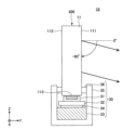
도 1은 실시형태의 탁상 조명 장치(10)의 외관도이다. 탁상 조명 장치(10)는 데스크, 테이블 등(이하, 「데스크(2)」라고 총칭함) 위에 적재된다. 탁상 조명 장치(10)가 적재되는 면을 「설치면(2p)」이라고 한다. 설치면(2p)과 평행한 면을 X-Y면, X-Y면과 직교하는 방향을 Z 방향이라고 한다. 탁상 조명 장치(1)의 높이 방향은 Z 방향, 폭 방향은 X 방향이 된다. 광의 출사 방향을 Y 방향이라고 한다.1 is an external view of a
탁상 조명 장치(10)는 도광판(11)을 포함하고, 광원으로부터의 광을 도광하는 도광부(300)를 갖는다. 도 1에서 광원은 생략되어 있지만, 광원은 설치면(2p)에 형성된 홈 또는 슬롯의 내부에 수용되어 있어도 좋고, 도광판(11)과 함께 설치면(2p) 상에 위치해도 좋다. 광원의 구성예에 대해서는 후술한다.The
도광판(11)은 가시광에 대하여 투명한 고체이며, 유리, 플라스틱 등으로 형성된다. 유리 재료로서, 석영 유리, 무알칼리 유리, 붕규산 유리 등을 사용할 수 있다. 플라스틱 재료로서, 아크릴계 수지(예를 들면, 폴리메틸메타크릴레이트(PMMA)), 폴리카보네이트(PC) 수지, 시클로올레핀계(COP) 수지 등을 사용할 수 있다. 도광판(11)의 가시광 투과율은 60% 이상, 65% 이상, 70% 이상, 75% 이상, 80% 이상, 85% 이상 또는 90% 이상이다. 가시광 투과율은 분광 광도계를 사용해서 측정 파장 380㎚ 이상 780㎚ 이하로 측정했을 때의 각 파장에 있어서의 투과율의 평균값으로서 특정된다.The
도광판(11)은 광을 출사하는 제 1 주면(111)을 갖는다. 제 1 주면(111)은 설치면(2p)에 대하여 거의 수직이다. 「거의 수직」이라고 할 때에는, 수직에 대하여 ±5° 정도의 오차를 포함해도 좋은 것을 의미한다. 제 1 주면(111)으로부터 출사되는 광은 설치면(2p)에 수평한 방향보다 하향으로 편향된 배광 분포를 가진다. 이 광 분포를 충족시키는 한, 제 1 주면(111)은 수직으로부터 ±5° 정도의 오차를 포함해도 좋다.The
제 1 주면(111)에 있어서, 제 1 주면(111)의 중심(C)을 통과하고, 또한 설치면(2p)에 대하여 수직한 축을 수직축, 또는 V축이라고 한다. V축을 포함하고, 설치면(2p)에 대하여 수직한 Y-Z 면내에서, 설치면(2p)과 평행한 방향을 수직 0°라고 한다. Y-Z 면내에서 수직 0°보다 상향의 각도를 플러스의 각도, 하향의 각도를 마이너스의 각도라고 한다.In the first
설치면(2p)과 직교하는 X-Z면에서의 중심(C)으로부터의 출사광의 배광 분포를 고려하면, 일반적으로는 -90°∼+90°의 범위에서 광의 출사가 가능하다. 이것에 대해, 탁상 조명 장치(10)에서는 제 1 주면(111)의 중심으로부터의 출사광의 배광 분포에 있어서 최대 강도가 되는 각도가 -90° 이상(예를 들면, -90° 초과), 0° 미만의 범위로 설정된다. 예를 들면, 그 상한은 -0.1°, -1°, -5°, -10°, -10°, -20°, -30°, -40°, -50°, -60°, -70°, -80°, -85°, -88°, -89°이며, 그 하한은 -90°, -89°, -88°, -85°, -80°, -70°, -60°, -50°, -40°, -30°, -20°, -10°, -5°, -1°이며, 하한의 값이 상한의 값을 초과하는 일은 없다. 또한, 출사광의 배광 분포는 시야각 측정기(예를 들면, ELDIM제의 휘도 시야각 측정기 EZContrast XL88)를 사용해서 측정할 수 있다.Considering the distribution of light emitted from the center C in the X-Z plane orthogonal to the
제 1 주면(111)에 있어서, 중심(C)을 통과하고, 또한 설치면(2p)과 수평한 축을 수평축, 또는 H축이라고 한다. 제 1 주면(111)의 중심(C)으로부터 Y 방향을 향하는 각도를 수평 0°라고 한다. 또한, 중심(C)을 통과하는 X-Y면을 설치면과는 반대측(또는 설치면의 상방)으로부터 본 경우에, 수평 0°∼시계 방향의 각도를 플러스의 각도, 반시계 방향의 각도를 마이너스의 각도라고 한다. X-Y 면내에서, 제 1 주면(111)으로부터 출사되는 광의 수평 방향의 분포는 -90°∼+90°의 범위 내이며, 예를 들면 -90° 초과 +90° 미만의 범위 내이며, 예를 들면 그 하한은 -90°, -89°, -88°, -85°, -80°, -70°, -60°, -50°, -40°, -30°, -20°, -10°이며, 그 상한은 +90°, +89°, +88°, +85°, +80°, +70°, +60°, +50°, +40°, +30°, +20°, +10°이다. 탁상 조명 장치(10)는 수평 방향에서는 거의 균일한 배광 분포여도 좋다.In the 1st
도 2는 탁상 조명 장치(10)의 수직 방향의 각도를 정의하는 도면, 도 3은 Y-Z 면내의 배광 특성을 나타내는 도면이다. 도 2 및 도 3의 좌표계는 도 1과 같다. 도 2에서, 설치면(2p)에 대하여 수직한 Y-Z 면에서 일반적으로 수직 방향으로 취득할 수 있는 각도 범위는 -90°∼+90°이다. 실시형태의 탁상 조명 장치(10)의 제 1 주면(111)은 도 3에 나타내는 바와 같이, 출사광의 배광 분포에 있어서 최대 강도가 되는 각도가 -90° 이상 0° 미만의 범위에 있도록 구성되어 있다.FIG. 2 is a diagram defining an angle in the vertical direction of the
출사면의 중심으로부터의 출사광의 배광 분포에 있어서 최대 강도가 되는 각도(즉, 도 3의 화살표가 이루는 각)를 -90° 이상 0° 미만의 범위로 설정함으로써, 설치면(2p)의 작업 에리어를 충분한 조도로 비춤과 아울러, 출사 광선이 직접 유저의 눈에 입사하는 것을 방지한다. 이것에 의해, 유저가 플리커링을 느끼는 것을 방지하고, 작업 효율의 저하를 억제한다.By setting the angle at which the maximum intensity is obtained in the light distribution of the emitted light from the center of the emission surface (i.e., the angle formed by the arrow in Fig. 3) within the range of -90° or more and less than 0°, the work area of the
도 4는 탁상 조명 장치(10)의 수평 방향의 각도를 정의하는 도면이고, 도 5는 X-Y 면내의 배광 특성을 나타내는 도면이다. 도 4 및 도 5의 좌표계는 도 1과 같다. 도 4에서 설치면(2p)과 수평한 X-Y 면내에서 수평 방향으로 취득할 수 있는 각도 범위는 -90°∼+90°이다. 탁상 조명 장치(10)의 제 1 주면(111)은 도 5에 나타내는 바와 같이, 출사광의 배광 분포는 수평 방향의 -90°∼+90°의 범위 내이다.FIG. 4 is a diagram defining angles in the horizontal direction of the
수평 방향의 배광 분포를 -90°∼+90°의 범위로 설정함으로써, 설치면(2p)의 작업 에리어를 거의 균일하게 비추고, 유저의 작업 효율을 향상시킬 수 있다.By setting the light distribution in the horizontal direction within the range of -90° to +90°, the work area on the
도 6은 탁상 조명 장치(10)의 광원부(30)의 구성예를 나타내는 도면이다. 광원부(30)의 구성을 설명하기 전에, 탁상 조명 장치(10)의 전체 구성을 간단히 설명한다. 탁상 조명 장치(10)는 광원부(30)와, 도광판(11)을 포함하고, 광원부(30)로부터 출사된 광을 도광하는 도광부(300)를 갖는다. 도광판(11)은 광원부(30)로부터의 광을 입사하는 광 입사면(113), 광 입사면(113)으로부터 입사한 광을 외부로 출사하는 제 1 주면(111), 및 제 1 주면(111)에 대향하는 제 2 주면(112)을 갖는다.6 is a diagram showing a configuration example of the
제 1 주면(111)은 상술한 바와 같이, 수직 방향으로 -90° 이상 0° 미만의 범위에서 광이 출사되도록 구성되어 있다. 제 1 주면(111)은 수평 방향에서 -90°∼+90°의 범위에서 광이 출사되는 구성이면 더욱 바람직하다.As described above, the first
도 6의 예에서는, 광 입사면(113)은 Z 방향에서 도광판(11)의 하단에 위치하고, 광원부(30)는 도광판(11)의 하방에 배치되어 있다. 후술하는 바와 같이, 광원부(30)의 배치는 이 예에 한정되지 않고, 도광판(11)의 측단부에 설치되어도 좋다.In the example of FIG. 6 , the
광원부(30)는, 예를 들면 하우징(35) 내에 수용된 발광 소자(31)를 광원으로서 갖는다. 발광 소자(31)는 기판(32)에 탑재되고, 열 전도성의 양면 테이프(34)에 의해 방열부(33)에 고정되어 있어도 좋다. 발광 소자를 바꾸고, 면 발광 가능한 유기 일렉트로루미네선스(EL) 발광체나 무기 EL 발광체, 또는 형광 램프나 냉음극관 등의 선상 광원을 사용해도 좋다.The
도광판(11)은 제 1 주면(111)이 탁상 조명 장치(10)의 설치면에 대하여 거의 수직이 되도록 유지 부재(36)에 의해 하우징(35)에 유지되어 있다. 광원부(30)는 하우징(35)과 데스크(2)에 형성된 홈이나 슬롯의 내부에 수용되어도 좋고, 하우징(35)과 데스크(2)의 표면에 적재해도 좋다.The
<도광부의 구성예><Configuration example of light guide part>
이어서, 도광부(300)의 구성예를 설명한다. 도 7a∼도 7c에서 도광부(300)는 도광판(11)의 제 1 주면(111)과 제 2 주면(112) 중 적어도 일방에 도광판(11)보다 굴절률이 낮은 저굴절률층을 갖는다. 저굴절률층은 도광판(11)의 굴절률에 대하여 굴절률이 낮은 층이다. 도광판(11)이 주로 PMMA를 포함해서 구성되는 경우, 도광판(11)의 굴절률 n1은 1.49 전후이다. 이것과 비교해서 저굴절률층의 굴절률 n2는, 바람직하게는 1.30 이하이며, 보다 바람직하게는 1.20 이하이다. 저굴절률층에 대해서는, 특별히 한정되지 않지만, 예를 들면 국제 공개 제2019/146628호에 개시된 공극을 갖는 저굴절률층을 사용할 수 있다. 이 내용은 참조에 의해 본원 명세서에 포함된다.Next, a configuration example of the
도광판(11) 및 저굴절률층을 갖는 도광부(300)의 가시광 투과율은 60% 이상, 65% 이상, 70% 이상, 75% 이상, 80% 이상, 85% 이상 또는 90% 이상이다. 가시광 투과율은 분광 광도계를 사용해서 측정 파장 380㎚ 이상 780㎚ 이하로 측정했을 때의 각 파장에 있어서의 투과율의 평균값으로서 특정된다.The visible light transmittance of the
도 7a에서, 탁상 조명 장치(10A)는 광원부(30)와, 도광판(11A)을 포함하는 도광부(300)를 갖는다. 광원부(30)는 도광판(11A)에 광을 출사하는 발광 소자(31)를 갖는다. 광원부(30)의 그 밖의 구성은 임의이며, 예를 들면 도 6의 구성을 채용할 수 있다.In Fig. 7A, the
도광판(11A)은 발광 소자(31)에 대향하는 광 입사면(113)과, 제 1 주면(111)과, 제 2 주면(112)을 갖고, 제 1 주면(111)에 저굴절률층(26)이 형성되어 있다. 저굴절률층(26)은 커버층(28a)으로 덮여 있어도 좋다.The
광 입사면(113)으로부터 도광판(11A)에 입사한 광은 저굴절률층(26)이 형성된 제 1 주면(111)과, 제 2 주면(112) 사이를 전반사하면서 도광판(11A)을 Z 방향으로 전파한다. 제 1 주면(111)과 저굴절률층(26)의 계면에 입사하는 광 중 전반사 조건을 충족시키지 않는 광은 제 1 주면(111)의 중심으로부터의 출사광의 배광 분포에 있어서 최대 강도가 되는 각도가 Y-Z 면에서 -90° 이상 0° 미만의 범위가 되도록 제 1 주면(111)으로부터 출사된다. 수평 방향(X-Y 면)에서는 출사광의 배광 분포는 -90°∼+90°의 범위의 분포를 갖고 있어도 좋다.The light incident on the
제 1 주면(111)에 저굴절률층(26)을 형성함으로써, 광 출사면의 오염이나 상처에 기인하는 광 손실을 억제할 수 있다.By forming the low
도 7b에서, 탁상 조명 장치(10B)는 광원부(30)와, 도광판(11B)을 포함하는 도광부(300)를 갖는다. 광원부(30)는 도광판(11B)에 광을 출사하는 발광 소자(31)를 갖는다. 광원부(30)의 그 밖의 구성은 임의이고, 예를 들면 도 6의 구성을 채용할 수 있다.In FIG. 7B, the
도광판(11B)은 발광 소자(31)에 대향하는 광 입사면(113)과, 제 1 주면(111)과, 제 2 주면(112)을 갖고, 제 2 주면(112)에 저굴절률층(27)이 형성되어 있다. 저굴절률층(26)은 커버층(28b)으로 덮여 있어도 좋다.The
광 입사면(113)으로부터 도광판(11B)에 입사한 광은 제 1 주면(111)과, 저굴절률층(27)이 형성된 제 2 주면(112)의 계면 사이를 전반사하면서 도광판(11B)을 Z 방향으로 전파한다. 제 1 주면(111)에 입사하는 광 중, 전반사 조건을 충족시키지 않는 광은 제 1 주면(111)의 중심으로부터의 출사광의 배광 분포에 있어서 최대 강도가 되는 각도가 Y-Z 면에서 -90° 이상 0° 미만의 범위가 되도록 제 1 주면(111)으로부터 출사된다. 수평 방향(X-Y 면)에서는 출사광의 배광 분포는 -90°∼+90°의 범위의 분포를 갖고 있어도 좋다.The light incident on the
제 2 주면(112)에 저굴절률층(27)을 형성함으로써, 제 2 주면(112)의 오염이나 상처에 기인하는 광 손실을 억제하고, 효율적으로 광을 제 1 주면(111)의 방향으로 향할 수 있다.By forming the low
도 7c에서, 탁상 조명 장치(10C)는 광원부(30)과, 도광판(11C)을 포함하는 도광부(300)를 갖는다. 광원부(30)는 도광판(11C)에 입사되는 광을 출력하는 발광 소자(31)를 갖는다. 광원부(30)의 그 밖의 구성은 임의이고, 예를 들면 도 6과 마찬가지의 구성을 채용할 수 있다.In Fig. 7C, the
도광판(11C)은 발광 소자(31)에 대향하는 광 입사면(113)과, 제 1 주면(111)과, 제 2 주면(112)을 갖는다. 제 1 주면(111)에 저굴절률층(26)이 형성되고, 제 2 주면(112)에 저굴절률층(27)이 형성되어 있다. 저굴절률층(26, 27)은 각각 커버층(28a, 28b)으로 덮여 있어도 좋다.The
광 입사면(113)으로부터 도광판(11C)에 입사한 광은 저굴절률층(26)이 형성된 제 1 주면(111)과, 저굴절률층(27)이 형성된 제 2 주면(112) 사이를 전반사하면서 도광판(11C)을 Z 방향으로 전파한다. 제 1 주면(111)과 저굴절률층(26)의 계면에 입사한 광 중 전반사 조건을 충족시키지 않는 광은 제 1 주면(111)의 중심으로부터의 출사광의 배광 분포에 있어서 최대 강도가 되는 각도가 Y-Z 면에서 -90° 이상 0° 미만의 범위가 되도록 출사된다. 수평 방향(X-Y면)에서는 출사광의 배광 분포는 -90°∼+90°의 범위의 분포를 갖고 있어도 좋다.The light incident on the
제 1 주면(111)과 제 2 주면(112)에 저굴절률층(26과 27)을 각각 형성함으로써, 도광판(11C)의 주면 상의 오염이나 상처에 기인하는 광 손실을 억제할 수 있다.By forming the low refractive index layers 26 and 27 on the first
도 8은 저굴절률층(26, 27)을 형성하는 것의 의의를 설명하는 도면이다. 제 1 주면(111) 또는 제 2 주면(112)에 피지, 땀 등의 오염(C1, C2)이 부착되어 있는 경우를 고려한다. 제 1 주면(111)과 제 2 주면(112) 사이를 전반사하면서 Z 방향으로 전파하는 광 중, 오염(C1 또는 C2)이 부착되어 있는 위치에 입사한 광은 오염(C1 또는 C2)에 의해 산란되고, 제 1 주면(111)으로부터 출사되기 전에 광 손실이 생긴다.Fig. 8 is a diagram explaining the significance of forming the low refractive index layers 26 and 27. A case in which contaminants C1 and C2 such as sebum and sweat adhere to the first
제 1 주면(111)과 제 2 주면(112) 중 적어도 일방에 저굴절률층(26 또는 27)을 형성함으로써, 도광판(11) 내부를 전파하는 광이 산란 등에 의해 소실되는 것을 방지할 수 있다. 그 결과, 제 1 주면(111)으로부터의 출사 효율을 높게 유지할 수 있다.By forming the low
<광 출사면의 구성예><Example of configuration of light exit surface>
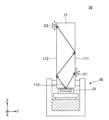
이어서, 도광판(11)의 광 출사면의 구성예를 나타낸다. 도 9은 탁상 조명 장치(10D)의 모식도이다. 탁상 조명 장치(10D)는 광원부(30)와, 도광판(11D)을 포함하는 도광부(300)를 갖는다. 광원부(30)는, 예를 들면 도 6을 참조해서 설명한 구성을 갖는다.Next, a configuration example of the light exit surface of the
도광판(11D)은 내부에 1개 이상의 광 캐비티(151)를 갖고, 제 1 주면(111)에 광 인출부(15)가 형성된다. 광 캐비티(151)는 도광판(11)보다 굴절률이 낮은 재료가 충전된 공극이다. 공극 내가 공기인 경우에는 에어 캐비티가 된다. 공기 이외에, 도광판(11)보다 굴절률이 낮은 기체, 액체, 고체의 재료가 충전되어도 좋다. 광 캐비티(151)는 도광판(11D)으로부터 광 캐비티(151)의 계면에 입사한 광이 제 1 주면(111)의 방향으로 전반사되고, 제 1 주면(111)의 중심으로부터의 출사광의 배광 분포에 있어서 최대 강도가 되는 각도가 Y-Z 면에서 -90° 이상 0° 미만의 범위가 되도록 설계되어 있다.The
도광판(11D) 및 광 인출부(15)를 갖는 도광부(300)의 가시광 투과율은 60% 이상, 65% 이상, 70% 이상, 75% 이상, 80% 이상, 85% 이상 또는 90% 이상이다. 가시광 투과율은 분광 광도계를 사용해서 측정 파장 380㎚ 이상 780㎚ 이하로 측정했을 때의 각 파장에 있어서의 투과율의 평균값으로서 특정된다.The visible light transmittance of the
도광판(11D)에는 제 1 주면(111)의 평면을 따라 복수의 광 캐비티(151)가 규칙적으로 또는 랜덤하게 설치되어 있다. 광 캐비티(151)의 크기는 도광판(11E)의 내부에 설치 가능한 범위에서 적절히 선택 가능하다. 광 캐비티를 내부에 포함하는 도광판에 대해서는 특별히 한정되지 않지만, 예를 들면 국제 공개 제2011/124765호, 국제 공개 제2011/127187호, 국제 공개 제2019/087118호, 국제 공개 제2019/182091호에 개시된 도광판을 사용할 수 있다. 이들 내용은 참조에 의해 본원명세서에 포함된다.In the
광 캐비티(151)를 내부에 포함하는 도광판(11D)은, 예를 들면 표면에 소망의 캐비티 패턴이 형성된 도광층과, 캐비티 패턴이 없는 평탄한 도광층을 접합함으로써 제작된다. 도광층끼리는 접착제 프리의 마이크로파 표면 처리 등의 라미네이션, 접착제(감압 접착제를 포함함)에 의한 압착 등으로 접합된다. 계면 반사를 억제하기 위해서, 접합되는 도광층의 굴절률은 거의 동등한 것이 바람직하다. 접착제를 사용하는 경우에는 도광층의 굴절률과 거의 동등한 굴절률의 접착제를 사용하는 것이 바람직하다.The
도광층으로의 캐비티 패턴의 형성은 레이저 패터닝, 다이렉트 레이저 이미징, 레이저 드릴, 마스크를 개재하거나 또는 마스크 리스의 레이저 조사나 전자 빔 조사 등으로 실시된다. 다른 방법으로서, 인쇄, 잉크젯 인쇄, 스크린 인쇄 등에 의해, 광 캐비티(151)가 되는 부분에 개별의 특성(굴절률값의 변화 등)을 부여해도 좋다. 마이크로/나노 디스펜스, 도우징, 다이렉트 라이팅, 이산적 레이저 소결, 마이크로 방전 가공(EDM: Electro-Discharge Machining), 마이크로머시닝, 마이크로 성형, 임프린팅, 엠보싱 가공 및 이것들과 유사한 것을 사용해도 좋다.Formation of the cavity pattern in the light guide layer is performed by laser patterning, direct laser imaging, laser drilling, or maskless laser irradiation or electron beam irradiation through a mask or the like. As another method, individual characteristics (change in refractive index value, etc.) may be imparted to the portion that becomes the
도광판(11D)에 의해, 광 입사면(113)으로부터 입사한 광을, 전반사로 Z 방향으로 전파시키면서 제 1 주면(111)으로부터 상술한 배광 분포로 사출할 수 있다.With the
도 10은 탁상 조명 장치(10E)의 모식도이다. 탁상 조명 장치(10E)는 광원부(30)와, 도광판(11E)을 포함하는 도광부(300)를 갖는다. 도광판(11E)은 제 1 주면(111)에 광 인출부로서 기능하는 광 인출층(16)이 설치되어 있다. 광 인출층(16)에는 1 이상의 광 캐비티(161)가 형성되어 있다.Fig. 10 is a schematic diagram of a
광 캐비티(161)를 갖는 광 인출층(16)은 도 9의 도광판(11D)과 마찬가지로, 캐비티 패턴이 없는 평탄한 도광층과, 표면에 캐비티 패턴이 형성된 도광층은 접합시켜 형성될 수 있다. 또는, 캐비티 패턴이 형성된 도광층을 직접, 제 1 주면(111)에 접합해도 좋다.Like the
바람직하지 않은 굴절이나 반사를 억제하는 관점에서, 광 인출층(16)의 굴절률과 도광판(11E)의 굴절률은 같거나 근접하고 있는 것이 바람직하다. 예를 들면, 도광판(11E)이 폴리메틸메타크릴레이트(PMMA)로 형성되어 있을 때에는 광 인출층(16)은 PMMA와 같거나 근접하는 굴절률의 재료로 형성된다.From the viewpoint of suppressing undesirable refraction or reflection, the refractive index of the
도광판(11E)으로부터 광 인출층(16)에 입사한 광은 광 캐비티(161)의 계면에서 전반사되고, 광 인출층(16)의 최외표면(162)으로부터 출사된다. 광 캐비티(161)의 계면은 도광판(11E)으로부터 입사한 광이 광 인출층(16)의 최외표면(162)의 방향으로 전반사되어, 제 1 주면(111)의 중심으로부터의 출사광의 배광 분포에 있어서 최대 강도가 되는 각도가 Y-Z 면내에서 -90° 이상 0° 미만의 각도 범위에서 출사되도록 설계되어 있다.Light incident on the
도광판(11E)에 의해, 광 입사면(113)으로부터 입사한 광을 전반사로 Z 방향으로 전파시키면서, 광 인출층(16)으로부터 상술한 배광 분포로 사출할 수 있다.With the
도 11은 탁상 조명 장치(10F)의 모식도이다. 탁상 조명 장치(10F)는 광원부(30)와, 도광판(11F)을 포함하는 도광부(300)를 갖는다. 도광판(11F)은 제 2 주면(112)에 광 인출부로서 기능하는 광 인출층(17)이 형성되어 있다. 광 인출층(17)에는 1개 이상의 광 캐비티(171)가 형성되어 있다.Fig. 11 is a schematic diagram of a
광 캐비티(171)를 갖는 광 인출층(17)은 도 9의 도광판(11D), 및 도 10의 광 인출층(16)과 마찬가지로, 캐비티 패턴이 없는 평탄한 도광층과, 표면에 캐비티 패턴이 형성된 도광층은 접합해서 형성될 수 있다. 또는, 캐비티 패턴이 형성된 도광층을 직접, 제 2 주면(112)에 접합해도 좋다.Like the
바람직하지 않은 굴절이나 반사를 억제하는 관점에서, 광 인출층(17)의 굴절률과 도광판(11F)의 굴절률은 같거나, 근접하고 있는 것이 바람직하다. 예를 들면, 도광판(11F)이 폴리메틸메타크릴레이트(PMMA)로 형성되어 있을 때에는, 광 인출층(17)은 PMMA와 같거나, 근접하는 굴절률의 재료로 형성된다.From the viewpoint of suppressing undesirable refraction or reflection, the refractive index of the
도광판(11F)으로부터 광 인출층(17)에 입사한 광은 광 캐비티(171)의 계면에서 전반사되어, 제 1 주면(111)의 방향으로 안내된다. 제 1 주면(111)에서는 상술한 바와 같이 제 1 주면(111)의 중심으로부터의 출사광의 배광 분포에 있어서 최대강도가 되는 각도는 Y-Z 면내에서 -90° 이상 0° 미만이다.Light incident on the
도광판(11F)에 의해, 광 입사면(113)으로부터 입사한 광을 전반사로 Z 방향으로 전파시키면서, 광 인출층(17)으로부터 제 1 주면(111)의 방향으로 광을 안내하고, 제 1 주면(111)으로부터 상술한 소정의 배광 분포로 출사할 수 있다.While propagating the light incident from the
도 9∼도 11 중 어느 구성에 의해서도, 작업 에리어를 충분한 조도로 비춤과 아울러, 출사 광선이 직접 유저의 눈에 입사하는 것을 방지하고, 플리커링을 억제할 수 있다.9 to 11, it is possible to illuminate the work area with sufficient illumination, prevent direct incident light on the user's eyes, and suppress flickering.
도 12는 탁상 조명 장치(10G)의 모식도이다. 탁상 조명 장치(10G)는 도광판(11G)을 포함하는 도광부(300)를 갖는다. 도광판(11G)은 제 1 주면(111)에 광 인출부로서의 프리즘부(251)가 설치되어 있다. 프리즘부(251)로서, 예를 들면 프리즘 시트를 제 1 주면(111)에 접합해도 좋다. 이 경우, 프리즘 시트와 도광판(11G)의 굴절률은 같거나, 또는 근접하고 있는 것이 바람직하다.Fig. 12 is a schematic diagram of a
프리즘부(251)의 크기, 경사면의 수 등은 제 1 주면(111)에 프리즘부(251)를 배치 가능한 범위에서 적절히 선택된다. 도광판(11G)으로부터 프리즘부(251)에 입사한 광은 프리즘부(251)에서 굴절되어 도광판(11G)으로부터 출사된다. 프리즘부(251)의 경사면의 각도와 피치는 상술한 바와 같이, 제 1 주면(111)의 중심으로부터의 출사광의 배광 분포에 있어서 최대 강도가 되는 각도가 Y-Z 면내에서 -90° 이상 0° 미만이 되도록 설계되어 있다.The size of the
도 13은 탁상 조명 장치(10H)의 모식도이다. 탁상 조명 장치(10H)는 도광판(11H)을 포함하는 도광부(300)를 갖는다. 도광판(11H)은 제 2 주면(112)에 광 인출부로서의 프리즘부(252)가 설치되어 있다. 프리즘부(252)로서, 예를 들면 프리즘 시트를 제 2 주면(112)에 접합해도 좋다. 이 경우, 프리즘 시트와 도광판(11H)의 굴절률은 같거나, 또는 근접하고 있는 것이 바람직하다.Fig. 13 is a schematic diagram of a
프리즘부(252)의 크기, 경사면의 수 등은 제 2 주면(112)에 프리즘부(252)를 배치 가능한 범위에서 적절히 선택된다. 도광판(11H)으로부터 프리즘부(252)에 입사한 광은 프리즘부(252)에 의해 제 1 주면(111)의 방향으로 굴절되어 제 1 주면(111)으로부터 출사된다. 프리즘부(252)의 경사면의 각도와 피치는 상술한 바와 같이, 제 1 주면(111)의 중심으로부터의 출사광의 배광 분포에 있어서 최대 강도가 되는 각도가 Y-Z 면내에서 -90° 이상 0° 미만이 되도록 설계되어 있다.The size of the
도 12 또는 도 13의 구성에 의해서도, 작업 에리어를 충분한 조도로 비춤과 아울러 출사 광선이 직접 유저의 눈에 입사하는 것을 방지하고, 플리커링을 억제할 수 있다.Even with the structure of FIG. 12 or FIG. 13, it is possible to illuminate the work area with sufficient illumination, prevent outgoing rays from directly entering the user's eyes, and suppress flickering.
도 14는 탁상 조명 장치(10I)의 모식도이다. 탁상 조명 장치(10I)는 도광판(11I)을 포함하는 도광부(300)를 갖는다. 도광판(11I)은 제 1 주면(111)에 광 인출부로서의 요철부(253)가 형성되어 있다. 요철부(253)는 1∼5㎛ 정도의 폭(또는 지름)과 높이의 복수의 볼록부, 또는 오목부를 갖는다. 요철부(253)는 제 1 주면(111)의 중심으로부터의 출사광의 배광 분포에 있어서 최대 강도가 되는 각도가 Y-Z 면내에서 -90° 이상 0° 미만이 되도록 설계되어 있다. 요철부(253)로서 상기 의 조건을 충족시키는 오목부와 볼록부가 형성된 광학 필름을 사용해도 좋다.Fig. 14 is a schematic diagram of the desk lighting device 10I. The tabletop lighting device 10I has a
도 15는 탁상 조명 장치(10J)의 모식도이다. 탁상 조명 장치(10J)는 도광판(11J)을 포함하는 도광부(300)를 갖는다. 도광판(11J)은 제 2 주면(112)에 광 인출부로서의 요철부(254)가 형성되어 있다. 요철부(254)는 1∼5㎛ 정도의 폭(또는 지름)과 높이의 복수의 볼록부 또는 오목부를 갖는다. 요철부(254)는 도광판(11J)으로부터 요철부(254)에 입사한 광을 제 1 주면(111)의 방향에 편향시키고, 제 1 주면(111)으로부터 출사시킨다. 요철부(254)는 제 1 주면(111)의 중심으로부터의 출사광의 배광 분포에 있어서 최대 강도가 되는 각도가 Y-Z 면내에서 -90° 이상 0° 미만이 되도록 설계되어 있다. 요철부(254)로서, 상기 조건을 충족시키는 오목부와 볼록부가 형성된 광학 필름을 사용해도 좋다.Fig. 15 is a schematic diagram of a
도 14 또는 도 15의 구성에 의해서도, 작업 에리어를 충분한 조도로 비춤과 아울러, 출사 광선이 직접 유저의 눈에 입사하는 것을 방지하고, 플리커링을 억제할 수 있다.Even with the structure of FIG. 14 or FIG. 15, it is possible to illuminate the work area with sufficient illuminance, prevent outgoing rays from directly entering the user's eyes, and suppress flickering.
<탁상 조명 장치의 사용 형태><Usage mode of tabletop lighting device>
도 16과 도 17은 탁상 조명 장치(10)의 사용 형태를 나타내는 도면이다. 도 16에서, 도광판(11)의 광 입사면(113)은 탁상 조명 장치(10)의 설치면(2p)과 평행하게 배치되고, 광원부(30)는 광 입사면(113)과 대향하도록 배치되어 있다. 광원부(30)에서 복수의 발광 소자(31)가 X 방향으로 배열되어 있다. 각 발광 소자(31)로부터 출력된 광은 도광판(11)의 하단의 광 입사면(113)에 입사하고, 도광판(11)을 Z 방향으로 전파하면서 도 3에 나타낸 배광 분포로 제 1 주면(111)으로부터 출력된다.16 and 17 are diagrams showing a usage mode of the
도 17에서 도광판(11)의 광 입사면(113)은 탁상 조명 장치(10)의 설치면(2p)에 대하여 수직으로 배치되고, 광원부(30)는 도광판(11)의 광 입사면(113)을 따라, 설치면(2p)으로부터 Z 방향으로 연장 설치되어 있다. 광원부(30)에서 복수의 발광 소자(31)는 Z 방향으로 배열되어 있다. 광원부(30)의 발광 소자(31)와 대향하는 도광판(11)의 측단면이, 광 입사면(113)이 된다.In FIG. 17 , the
각 발광 소자(31)로부터 출력된 광은 도광판(11)의 측단부의 광 입사면(113)에 입사하고, 도광판(11)을 X 방향으로 전파하면서, 도 3에 나타낸 배광 분포로 제 1 주면(111)으로부터 출력된다.The light output from each light emitting
도광판(11)은 가시광에 대하여 투명하므로, 도 16의 사용 형태라도 도 17의 사용 형태라도, 유저는 도광판(11)의 배후를 볼 수 있고, 개방적인 조명 공간이 제공된다.Since the
도 18은 탁상 조명 장치(10)의 효과를 설명하는 모식도이다. 탁상 조명 장치(10)에 있어서, 조명광은 수직 방향으로 -90° 이상 0° 미만의 범위로 출사된다. 출사광은 유저의 작업면과 바로 앞을 균일한 밝기로 비춘다. 유저는 작업면을 시인함과 아울러, 탁상 조명 장치(10)를 통해서 탁상 조명 장치(10)의 배후도 볼 수 있다.18 is a schematic diagram explaining the effect of the
한편, 크로스 마크로 나타내는 바와 같이, 탁상 조명 장치(10)로부터 출사되는 광을 직접 시인하는 경우는 거의 없다. 따라서, 플리커링감이 저감되어 작업 효율이 유지된다.On the other hand, as indicated by the cross marks, the light emitted from the
이상, 특정의 구성예에 의거해서 본 발명을 설명해 왔지만, 본 발명은 상술한 구성예에 한정되지 않는다. 도 7a∼도 7c의 저굴절률층을 설치하는 구성과, 도 9∼15의 광 인출 구성을 임의로 조합시켜도 좋다. 광원부(30)의 발광 소자(31)의 배열 방향은 수평 방향이어도 좋고 수직 방향이어도 좋다. 어느 경우라도, 투명한 도광판으로부터 유저가 직접 시인하기 어려운 방향으로 광을 출사함으로써 압박감이나 광의 플리커링이 저감된 개방적인 조명 공간이 실현된다.As mentioned above, although this invention has been demonstrated based on the specific structural example, this invention is not limited to the structural example mentioned above. You may arbitrarily combine the structure which provides the low refractive index layer of FIGS. 7A-7C, and the light extraction structure of FIGS. 9-15. The arrangement direction of the
본 출원은 2020년 7월 28일에 출원된 일본국 특허 출원 제2020-127348호에 의거해서 그 우선권을 주장하는 것이며, 이 일본국 특허 출원의 전체 내용을 포함한다.This application claims priority based on Japanese Patent Application No. 2020-127348 filed on July 28, 2020, and includes all contents of this Japanese Patent Application.
2p: 설치면 10, 10A∼10J: 탁상 조명 장치
11, 11A∼11J: 도광판 111: 제 1 주면
112: 제 2 주면 113: 광 입사면
15: 광 인출부 151: 광 캐비티(공극)
16, 17: 광 인출층 161, 171: 광 캐비티(공극)
162: 최외표면 26, 27: 저굴절률층
28a, 28b: 커버층 30: 광원부
31: 발광 소자 251, 252: 프리즘부
253, 254: 요철부 300: 도광부2p:
11, 11A to 11J: light guide plate 111: first main surface
112: second main surface 113: light incident surface
15: light extraction unit 151: optical cavity (air gap)
16, 17:
162
28a, 28b: cover layer 30: light source unit
31:
253, 254: uneven part 300: light guiding part
Claims (12)
상기 도광판은 상기 광원으로부터의 광을 입사하는 광 입사면, 상기 광 입사면으로부터 입사한 광을 출사하는 제 1 주면, 및 상기 제 1 주면에 대향하는 제 2 주면을 갖고,
상기 제 1 주면은 탁상 조명 장치의 설치면에 대하여 거의 수직으로 배치되고,
상기 제 1 주면의 중심을 통과하고, 또한 상기 설치면에 대하여 수직한 축을 수직축으로 하고, 상기 수직축을 포함해 상기 설치면에 대하여 수직한 면내에서, 상기 설치면과 평행한 방향을 수직 0°, 상기 평행한 방향보다 상향의 각도를 플러스의 각도, 상기 평행한 방향보다 하향의 각도를 마이너스의 각도라고 했을 때에, 상기 제 1 주면으로부터 출사되는 광의 배광 분포에 있어서 최대 강도가 되는 각도는 -90° 이상 0°미만인 탁상 조명 장치.A desk lighting device including a light source and a light guide plate, and having a light guide portion for guiding light emitted from the light source,
The light guide plate has a light incident surface for receiving light from the light source, a first main surface for emitting light incident from the light incident surface, and a second main surface facing the first main surface;
The first main surface is disposed substantially perpendicular to the installation surface of the tabletop lighting device,
An axis passing through the center of the first principal surface and perpendicular to the installation surface is taken as a vertical axis, and a direction parallel to the installation surface within a plane perpendicular to the installation surface including the vertical axis is perpendicular to 0°, When an angle upward from the parallel direction is a positive angle, and an angle downward from the parallel direction is a negative angle, the angle at which the maximum intensity in the distribution of light emitted from the first principal surface is -90°. A tabletop lighting device that is greater than or equal to less than 0°.
상기 제 1 주면에 있어서 상기 제 1 주면의 중심을 통과하고, 또한 상기 설치면과 수평한 축을 수평축이라고 하면, 상기 수평축을 포함해 상기 설치면과 평행한 면내에서, 광 출사면의 중심으로부터 광 출사면을 향하는 방향이며 상기 광 출사면과 직교하는 방향을 수평 0°, 상기 평행한 면을 상기 설치면과 반대측으로부터 보았을 때에 0° 방향으로부터 시계 회전의 방향을 플러스의 각도, 반시계 회전의 방향을 마이너스의 각도라고 정의했을 때에, 상기 제 1 주면의 중심으로부터의 출사광의 수평 방향의 배광 분포는 -90°∼+90°의 범위 내인 탁상 조명 장치.According to claim 1,
If an axis passing through the center of the first main surface and parallel to the installation surface is referred to as a horizontal axis, light exits from the center of the light exit surface within a plane parallel to the installation surface including the horizontal axis. The direction toward the surface and the direction orthogonal to the light exit surface is horizontal 0°, the clockwise direction from the 0° direction when the parallel surface is viewed from the side opposite to the installation surface is a positive angle, and the counterclockwise direction is When defined as a negative angle, the distribution of light emitted from the center of the first main surface in the horizontal direction is within the range of -90° to +90°.
상기 도광부는 가시광에 대하여 투과성을 갖는 탁상 조명 장치.According to claim 1 or 2,
The light guiding part has transmittance to visible light.
상기 도광부는 상기 제 1 주면과 상기 제 2 주면 중 적어도 일방에, 상기 도광판보다 굴절률이 낮은 저굴절률층을 갖는 탁상 조명 장치.According to any one of claims 1 to 3,
The light guide portion includes a low refractive index layer having a refractive index lower than that of the light guide plate on at least one of the first main surface and the second main surface.
상기 도광부는 상기 제 1 주면과 상기 제 2 주면의 양방에 상기 저굴절률층을 갖는 탁상 조명 장치.According to claim 4,
The light guide portion has the low refractive index layer on both the first main surface and the second main surface.
상기 도광부는 상기 도광판을 전파하는 광을 상기 제 1 주면으로부터 상기 배광 분포로 출사하는 광 인출부를 갖는 탁상 조명 장치.According to any one of claims 1 to 5,
The light guide unit has a light extraction unit for emitting light propagating through the light guide plate from the first main surface to the light distribution distribution.
상기 광 인출부는 상기 도광판의 내부에 형성된 1개 이상의 공극이며, 상기 공극은 상기 도광판을 전파하는 상기 광을 전반사하고, 상기 제 1 주면으로부터 상기 배광 분포로 출사하는 탁상 조명 장치.According to claim 6,
The light extraction unit is one or more air gaps formed inside the light guide plate, and the air gaps totally reflect the light propagating through the light guide plate and emit the light from the first main surface to the light distribution distribution.
상기 광 인출부는 상기 제 1 주면에 배치되는 광 인출층이며,
상기 광 인출층은 상기 도광판으로부터 상기 광 인출층으로 입사한 광을 전반사해서 상기 광 인출층의 최외표면으로부터 출사하는 1개 이상의 공극을 갖는 탁상 조명 장치.According to claim 6,
The light extraction unit is a light extraction layer disposed on the first main surface,
The light extraction layer has one or more air gaps in which the light incident from the light guide plate to the light extraction layer is totally reflected and emitted from the outermost surface of the light extraction layer.
상기 광 인출부는 상기 제 2 주면에 배치되는 광 인출층이며,
상기 광 인출층은 상기 도광판으로부터 상기 광 인출층에 입사한 광을 전반사해서 상기 제 1 주면의 방향으로 출사하는 1개 이상의 공극을 갖는 탁상 조명 장치.According to claim 6,
The light extraction unit is a light extraction layer disposed on the second main surface,
The light extraction layer has one or more air gaps for total reflection of the light incident on the light extraction layer from the light guide plate and radiating it in the direction of the first principal surface.
상기 광 인출부는, 상기 제 2 주면에 배치되어서 상기 도광판을 전파하는 광을 상기 제 1 주면의 방향을 향하는 프리즘부, 또는 요철부인 탁상 조명 장치.According to claim 6,
The light extraction part is a prism part or a concave-convex part disposed on the second main surface to direct the light propagating through the light guide plate toward the first main surface.
상기 도광판의 상기 광 입사면은 상기 설치면과 평행이 되도록 배치되는 탁상 조명 장치.According to any one of claims 1 to 10,
The light incident surface of the light guide plate is arranged to be parallel to the installation surface.
상기 도광판의 상기 광 입사면은 상기 설치면에 대하여 수직이 되도록 배치되는 탁상 조명 장치.According to any one of claims 1 to 10,
The light incident surface of the light guide plate is arranged to be perpendicular to the installation surface.
Applications Claiming Priority (3)
| Application Number | Priority Date | Filing Date | Title |
|---|---|---|---|
| JP2020127348 | 2020-07-28 | ||
| JPJP-P-2020-127348 | 2020-07-28 | ||
| PCT/JP2021/026903 WO2022024829A1 (en) | 2020-07-28 | 2021-07-19 | Tabletop lighting device |
Publications (1)
| Publication Number | Publication Date |
|---|---|
| KR20230044187A true KR20230044187A (en) | 2023-04-03 |
Family
ID=80036426
Family Applications (1)
| Application Number | Title | Priority Date | Filing Date |
|---|---|---|---|
| KR1020237001987A KR20230044187A (en) | 2020-07-28 | 2021-07-19 | desk light unit |
Country Status (7)
| Country | Link |
|---|---|
| US (1) | US11940120B2 (en) |
| EP (1) | EP4191125A4 (en) |
| JP (1) | JPWO2022024829A1 (en) |
| KR (1) | KR20230044187A (en) |
| CN (1) | CN116157618A (en) |
| TW (1) | TW202204816A (en) |
| WO (1) | WO2022024829A1 (en) |
Families Citing this family (1)
| Publication number | Priority date | Publication date | Assignee | Title |
|---|---|---|---|---|
| EP4191122A4 (en) * | 2020-07-28 | 2024-08-07 | Nitto Denko Corp | Surface illuminating device, space including surface illuminating device, and illumination method |
Citations (1)
| Publication number | Priority date | Publication date | Assignee | Title |
|---|---|---|---|---|
| JP2009110783A (en) | 2007-10-30 | 2009-05-21 | Colcoat Kk | Directional lighting apparatus |
Family Cites Families (17)
| Publication number | Priority date | Publication date | Assignee | Title |
|---|---|---|---|---|
| JPH08248421A (en) * | 1995-03-07 | 1996-09-27 | Sony Corp | Light transmission member |
| JP2003202568A (en) | 2001-10-24 | 2003-07-18 | Sharp Corp | Light guide, its manufacturing method, surface-like light source, and display device |
| JP2011028868A (en) * | 2009-07-21 | 2011-02-10 | Inax Corp | Lighting device of kitchen |
| US20110244187A1 (en) | 2010-04-06 | 2011-10-06 | Modilis Holdings Llc | Internal Cavity Optics |
| JP2013524282A (en) | 2010-04-06 | 2013-06-17 | オーワイ アイシーエス インテリジェント コントロール システムズ リミテッド | Laminated structure with embedded cavities used in solar cells and related manufacturing methods |
| TWI416049B (en) * | 2010-09-10 | 2013-11-21 | Young Lighting Technology Corp | Light source apparatus and method of using light source apparatus |
| JP2012156082A (en) | 2011-01-28 | 2012-08-16 | Furukawa Electric Co Ltd:The | Backlight panel, light guide plate, reflection plate, and adhesive sheet |
| US8998478B2 (en) | 2011-04-20 | 2015-04-07 | Rambus Delaware Llc | Lighting assembly |
| JP2013200993A (en) * | 2012-03-23 | 2013-10-03 | Konica Minolta Inc | Light guide plate, lighting device, and light stand |
| SG11201702889QA (en) * | 2014-10-21 | 2017-05-30 | Saint Gobain Adfors | A panel with integrated illumination |
| WO2019087118A1 (en) | 2017-11-01 | 2019-05-09 | Nitto Denko Corporation | Light distribution structure and element, related method and uses |
| WO2019134892A1 (en) * | 2018-01-02 | 2019-07-11 | Signify Holding B.V. | Table lamp |
| WO2019146628A1 (en) | 2018-01-26 | 2019-08-01 | 日東電工株式会社 | Film for led lighting equipment, and led lighting equipment |
| TWI816767B (en) * | 2018-03-22 | 2023-10-01 | 日商日東電工股份有限公司 | Optical components and manufacturing methods |
| TW202012834A (en) * | 2018-05-21 | 2020-04-01 | 日商日東電工股份有限公司 | Improved light distribution element |
| CH715534A1 (en) * | 2018-11-12 | 2020-05-15 | Regent Beleuchtungskoerper Ag | Optics and table lamp. |
| JP2020127348A (en) | 2019-02-06 | 2020-08-20 | Njコンポーネント株式会社 | Stator, motor, and manufacturing method of stator |
-
2021
- 2021-07-19 CN CN202180059492.XA patent/CN116157618A/en active Pending
- 2021-07-19 JP JP2022540196A patent/JPWO2022024829A1/ja active Pending
- 2021-07-19 KR KR1020237001987A patent/KR20230044187A/en active Search and Examination
- 2021-07-19 EP EP21849448.2A patent/EP4191125A4/en active Pending
- 2021-07-19 US US18/017,503 patent/US11940120B2/en active Active
- 2021-07-19 WO PCT/JP2021/026903 patent/WO2022024829A1/en active Application Filing
- 2021-07-23 TW TW110127133A patent/TW202204816A/en unknown
Patent Citations (1)
| Publication number | Priority date | Publication date | Assignee | Title |
|---|---|---|---|---|
| JP2009110783A (en) | 2007-10-30 | 2009-05-21 | Colcoat Kk | Directional lighting apparatus |
Also Published As
| Publication number | Publication date |
|---|---|
| CN116157618A (en) | 2023-05-23 |
| JPWO2022024829A1 (en) | 2022-02-03 |
| US20230280005A1 (en) | 2023-09-07 |
| EP4191125A1 (en) | 2023-06-07 |
| TW202204816A (en) | 2022-02-01 |
| WO2022024829A1 (en) | 2022-02-03 |
| US11940120B2 (en) | 2024-03-26 |
| EP4191125A4 (en) | 2024-08-14 |
Similar Documents
| Publication | Publication Date | Title |
|---|---|---|
| JP3982799B2 (en) | Illumination device and reflective liquid crystal display device using the same | |
| JP5297522B2 (en) | Luminous body | |
| CN102472454B (en) | Light-guiding plate, light-guiding plate manufacturing method, surface light-source device, and liquid crystal display device | |
| WO2012063759A1 (en) | Led lighting device | |
| JP6223746B2 (en) | Single-sided light-emitting transparent light guide plate and surface light-emitting device using this light guide plate | |
| US9453958B2 (en) | Light guide plate and illumination apparatus | |
| JP2007256910A (en) | Surface light source device, backlight unit with same and liquid crystal display provided with backlight unit | |
| KR20230044187A (en) | desk light unit | |
| JP6418486B2 (en) | Light guide plate and lighting device | |
| CN102859264A (en) | Backlight device and liquid crystal display device | |
| KR20230047081A (en) | Area lighting device, space including area lighting device, and lighting method | |
| JP5442533B2 (en) | Luminous body | |
| WO2013154038A1 (en) | Illumination device and display device provided with same | |
| JP3889958B2 (en) | Surface light emitter and liquid crystal display device | |
| JP5389717B2 (en) | Front light device and liquid crystal display device | |
| JP2018044994A (en) | Display | |
| US20230296242A1 (en) | Construction | |
| EP4191123A1 (en) | Lighting device | |
| WO2013154124A1 (en) | Illumination device and display device provided with same | |
| CN116348708A (en) | Lighting device | |
| JP2014146468A (en) | Light guide plate | |
| KR20120102614A (en) | Lighting device | |
| US20090097278A1 (en) | Light Indicator | |
| KR20120056468A (en) | Light emitting module, backlight unit and display device including the same | |
| JPH0772333A (en) | Pilot lamp |
Legal Events
| Date | Code | Title | Description |
|---|---|---|---|
| A201 | Request for examination |