KR20230040407A - Cooling apparatus for fuel cell vehicle - Google Patents
Cooling apparatus for fuel cell vehicle Download PDFInfo
- Publication number
- KR20230040407A KR20230040407A KR1020210123089A KR20210123089A KR20230040407A KR 20230040407 A KR20230040407 A KR 20230040407A KR 1020210123089 A KR1020210123089 A KR 1020210123089A KR 20210123089 A KR20210123089 A KR 20210123089A KR 20230040407 A KR20230040407 A KR 20230040407A
- Authority
- KR
- South Korea
- Prior art keywords
- cooling efficiency
- storage tank
- efficiency improving
- fuel storage
- unit
- Prior art date
- Legal status (The legal status is an assumption and is not a legal conclusion. Google has not performed a legal analysis and makes no representation as to the accuracy of the status listed.)
- Pending
Links
Images

Classifications
-
- F—MECHANICAL ENGINEERING; LIGHTING; HEATING; WEAPONS; BLASTING
- F01—MACHINES OR ENGINES IN GENERAL; ENGINE PLANTS IN GENERAL; STEAM ENGINES
- F01P—COOLING OF MACHINES OR ENGINES IN GENERAL; COOLING OF INTERNAL-COMBUSTION ENGINES
- F01P1/00—Air cooling
- F01P1/06—Arrangements for cooling other engine or machine parts
-
- B—PERFORMING OPERATIONS; TRANSPORTING
- B60—VEHICLES IN GENERAL
- B60K—ARRANGEMENT OR MOUNTING OF PROPULSION UNITS OR OF TRANSMISSIONS IN VEHICLES; ARRANGEMENT OR MOUNTING OF PLURAL DIVERSE PRIME-MOVERS IN VEHICLES; AUXILIARY DRIVES FOR VEHICLES; INSTRUMENTATION OR DASHBOARDS FOR VEHICLES; ARRANGEMENTS IN CONNECTION WITH COOLING, AIR INTAKE, GAS EXHAUST OR FUEL SUPPLY OF PROPULSION UNITS IN VEHICLES
- B60K15/00—Arrangement in connection with fuel supply of combustion engines or other fuel consuming energy converters, e.g. fuel cells; Mounting or construction of fuel tanks
- B60K15/03—Fuel tanks
- B60K15/063—Arrangement of tanks
- B60K15/067—Mounting of tanks
- B60K15/07—Mounting of tanks of gas tanks
-
- B—PERFORMING OPERATIONS; TRANSPORTING
- B62—LAND VEHICLES FOR TRAVELLING OTHERWISE THAN ON RAILS
- B62D—MOTOR VEHICLES; TRAILERS
- B62D25/00—Superstructure or monocoque structure sub-units; Parts or details thereof not otherwise provided for
- B62D25/20—Floors or bottom sub-units
- B62D25/2072—Floor protection, e.g. from corrosion or scratching
-
- F—MECHANICAL ENGINEERING; LIGHTING; HEATING; WEAPONS; BLASTING
- F01—MACHINES OR ENGINES IN GENERAL; ENGINE PLANTS IN GENERAL; STEAM ENGINES
- F01P—COOLING OF MACHINES OR ENGINES IN GENERAL; COOLING OF INTERNAL-COMBUSTION ENGINES
- F01P9/00—Cooling having pertinent characteristics not provided for in, or of interest apart from, groups F01P1/00 - F01P7/00
- F01P9/02—Cooling by evaporation, e.g. by spraying water on to cylinders
-
- B—PERFORMING OPERATIONS; TRANSPORTING
- B60—VEHICLES IN GENERAL
- B60K—ARRANGEMENT OR MOUNTING OF PROPULSION UNITS OR OF TRANSMISSIONS IN VEHICLES; ARRANGEMENT OR MOUNTING OF PLURAL DIVERSE PRIME-MOVERS IN VEHICLES; AUXILIARY DRIVES FOR VEHICLES; INSTRUMENTATION OR DASHBOARDS FOR VEHICLES; ARRANGEMENTS IN CONNECTION WITH COOLING, AIR INTAKE, GAS EXHAUST OR FUEL SUPPLY OF PROPULSION UNITS IN VEHICLES
- B60K15/00—Arrangement in connection with fuel supply of combustion engines or other fuel consuming energy converters, e.g. fuel cells; Mounting or construction of fuel tanks
- B60K15/03—Fuel tanks
- B60K15/03006—Gas tanks
- B60K2015/03019—Filling of gas tanks
-
- B—PERFORMING OPERATIONS; TRANSPORTING
- B60—VEHICLES IN GENERAL
- B60Y—INDEXING SCHEME RELATING TO ASPECTS CROSS-CUTTING VEHICLE TECHNOLOGY
- B60Y2200/00—Type of vehicle
- B60Y2200/90—Vehicles comprising electric prime movers
- B60Y2200/91—Electric vehicles
-
- B—PERFORMING OPERATIONS; TRANSPORTING
- B60—VEHICLES IN GENERAL
- B60Y—INDEXING SCHEME RELATING TO ASPECTS CROSS-CUTTING VEHICLE TECHNOLOGY
- B60Y2306/00—Other features of vehicle sub-units
- B60Y2306/05—Cooling
-
- F—MECHANICAL ENGINEERING; LIGHTING; HEATING; WEAPONS; BLASTING
- F01—MACHINES OR ENGINES IN GENERAL; ENGINE PLANTS IN GENERAL; STEAM ENGINES
- F01P—COOLING OF MACHINES OR ENGINES IN GENERAL; COOLING OF INTERNAL-COMBUSTION ENGINES
- F01P2050/00—Applications
- F01P2050/22—Motor-cars
-
- F—MECHANICAL ENGINEERING; LIGHTING; HEATING; WEAPONS; BLASTING
- F01—MACHINES OR ENGINES IN GENERAL; ENGINE PLANTS IN GENERAL; STEAM ENGINES
- F01P—COOLING OF MACHINES OR ENGINES IN GENERAL; COOLING OF INTERNAL-COMBUSTION ENGINES
- F01P2050/00—Applications
- F01P2050/24—Hybrid vehicles
-
- Y—GENERAL TAGGING OF NEW TECHNOLOGICAL DEVELOPMENTS; GENERAL TAGGING OF CROSS-SECTIONAL TECHNOLOGIES SPANNING OVER SEVERAL SECTIONS OF THE IPC; TECHNICAL SUBJECTS COVERED BY FORMER USPC CROSS-REFERENCE ART COLLECTIONS [XRACs] AND DIGESTS
- Y02—TECHNOLOGIES OR APPLICATIONS FOR MITIGATION OR ADAPTATION AGAINST CLIMATE CHANGE
- Y02E—REDUCTION OF GREENHOUSE GAS [GHG] EMISSIONS, RELATED TO ENERGY GENERATION, TRANSMISSION OR DISTRIBUTION
- Y02E60/00—Enabling technologies; Technologies with a potential or indirect contribution to GHG emissions mitigation
- Y02E60/30—Hydrogen technology
- Y02E60/50—Fuel cells
-
- Y—GENERAL TAGGING OF NEW TECHNOLOGICAL DEVELOPMENTS; GENERAL TAGGING OF CROSS-SECTIONAL TECHNOLOGIES SPANNING OVER SEVERAL SECTIONS OF THE IPC; TECHNICAL SUBJECTS COVERED BY FORMER USPC CROSS-REFERENCE ART COLLECTIONS [XRACs] AND DIGESTS
- Y02—TECHNOLOGIES OR APPLICATIONS FOR MITIGATION OR ADAPTATION AGAINST CLIMATE CHANGE
- Y02T—CLIMATE CHANGE MITIGATION TECHNOLOGIES RELATED TO TRANSPORTATION
- Y02T90/00—Enabling technologies or technologies with a potential or indirect contribution to GHG emissions mitigation
- Y02T90/40—Application of hydrogen technology to transportation, e.g. using fuel cells
Landscapes
- Engineering & Computer Science (AREA)
- Chemical & Material Sciences (AREA)
- Combustion & Propulsion (AREA)
- Mechanical Engineering (AREA)
- Transportation (AREA)
- General Engineering & Computer Science (AREA)
- Life Sciences & Earth Sciences (AREA)
- Sustainable Development (AREA)
- Sustainable Energy (AREA)
- Physics & Mathematics (AREA)
- Thermal Sciences (AREA)
- Fuel Cell (AREA)
Abstract
Description
본 발명은 연료전지 차량용 냉각 장치에 관한 것으로, 보다 상세하게는 수소 연료전지 차량의 하부커버의 구조를 개선한 연료전지 차량용 냉각 장치에 관한 것이다.The present invention relates to a cooling device for a fuel cell vehicle, and more particularly, to a cooling device for a fuel cell vehicle having an improved structure of a lower cover of a hydrogen fuel cell vehicle.
일반적으로, 최근 차세대 자동차로 EV/HEV/PHEV 등 하이브라이드 차에 이어 최근 들어 수소 연료전지 차량(FCEV)의 개발이 활발히 진행되고 있다. In general, recently, as a next-generation vehicle, following hybrid vehicles such as EV/HEV/PHEV, hydrogen fuel cell vehicles (FCEVs) have been actively developed.
수소연료전지 차량에서는 차량의 주행 거리 증대를 위하여 제한된 공간에 최대한 많은 수소를 수용해아 하므로, 수소 가스를 압축하여 저장한다. 이때, 수소 저장 방식으로 기체상태의 수소를 압축하여 고압 탱크에 저장하는 방식이 사용되는 것이 일반적이다.In a hydrogen fuel cell vehicle, hydrogen gas is compressed and stored in order to accommodate as much hydrogen as possible in a limited space in order to increase the mileage of the vehicle. At this time, it is common to use a method of compressing gaseous hydrogen and storing it in a high-pressure tank as a hydrogen storage method.
수소 저장탱크는 온도에 특히 약한 수소의 특성상, 수소의 급속 충진시 수소의 온도 및 탱크의 압력이 급격히 상승하게 된다. 이러한 온도와 압력의 급격한 변화에 의해 수소 저장탱크가 파손되며, 수소 충전 효율이 저하되는 문제점이 있다.Due to the characteristics of hydrogen, which is particularly vulnerable to temperature, the hydrogen storage tank rapidly increases the temperature and pressure of the hydrogen tank when rapidly charging the hydrogen. There is a problem in that the hydrogen storage tank is damaged by such rapid changes in temperature and pressure, and the hydrogen charging efficiency is lowered.
본 발명의 배경기술은 대한민국 공개특허공보 제10-1999-0002271호(1999.01.15 공개, 발명의 명칭: 차량 엔진룸의 언더커버)에 개시되어 있다.The background art of the present invention is disclosed in Republic of Korea Patent Publication No. 10-1999-0002271 (published on January 15, 1999, title of the invention: vehicle engine room under cover).
본 발명은 수소 연료전지 차량의 하부커버를 활용하여 충전 효율을 향상시키고, 효율적인 열관리가 가능한 연료전지 차량용 냉각 장치를 제공하는데 그 목적이 있다.An object of the present invention is to provide a cooling device for a fuel cell vehicle that can improve charging efficiency and efficiently manage heat by utilizing a lower cover of a hydrogen fuel cell vehicle.
상술한 과제를 해결하기 위해 본 발명에 따른 연료전지 차량용 냉각 장치는: 연료를 저장하는 연료저장탱크와; 상기 연료저장탱크의 일측에 설치되어 상기 연료저장탱크를 커버하는 커버부; 및 상기 커버부에 구비되고, 상기 연료저장탱크의 냉각 효율을 향상시키는 냉각효율향상부;를 포함한다.In order to solve the above problems, a cooling device for a fuel cell vehicle according to the present invention includes: a fuel storage tank for storing fuel; a cover unit installed on one side of the fuel storage tank to cover the fuel storage tank; and a cooling efficiency improving unit provided in the cover unit and improving cooling efficiency of the fuel storage tank.
또한, 상기 냉각효율향상부는 차량의 하방을 유동하는 공기가 상기 연료저장탱크를 향해 통과되는 것을 허용한다.In addition, the cooling efficiency improving unit allows air flowing below the vehicle to pass toward the fuel storage tank.
또한, 상기 냉각효율향상부는 상기 연료저장탱크로부터 발생되는 수분의 증발을 유도한다.In addition, the cooling efficiency improving unit induces evaporation of moisture generated from the fuel storage tank.
또한, 상기 냉각효율향상부는 다공성 구조를 갖는다.In addition, the cooling efficiency improving part has a porous structure.
또한, 상기 냉각효율향상부는, 상기 연료저장탱크와 마주보게 배치되는 제1냉각효율향상부재; 및 상기 제1냉각효율향상부재와 연통되고, 지면과 마주보게 배치되는 제2냉각효율향상부재;를 포함한다.In addition, the cooling efficiency improving unit may include a first cooling efficiency improving member disposed to face the fuel storage tank; and a second cooling efficiency improving member communicating with the first cooling efficiency improving member and facing the ground.
또한, 상기 제2냉각효율향상부재의 기공률은 상기 제1냉각효율향상부재의 기공률보다 작다.In addition, the porosity of the second cooling efficiency improving member is smaller than the porosity of the first cooling efficiency improving member.
또한, 제2냉각효율향상부재는, 상기 제1냉각효율향상부재와 마주보게 배치되고, 이물질의 통과를 차단하는 제2바디부; 및 상기 제2바디부를 관통하여 형성되고, 상기 연료저장탱크로부터 발생되는 수분을 저장하는 수분저장부;를 포함한다.In addition, the second cooling efficiency improving member may include a second body portion disposed to face the first cooling efficiency improving member and blocking the passage of foreign substances; and a water storage unit formed penetrating the second body and storing water generated from the fuel storage tank.
본 발명에 따른 연료전지 차량용 냉각 장치는 다공성 구조를 갖는 냉각효율향상부에 의해 차량의 하방을 유동하는 공기가 연료저장탱크와 직접 접촉되도록 유도함으로써 연료저장탱크를 보다 신속하고 효율적으로 냉각시킬 수 있다.The cooling device for a fuel cell vehicle according to the present invention can cool the fuel storage tank more quickly and efficiently by directing the air flowing below the vehicle to come into direct contact with the fuel storage tank by the cooling efficiency improving unit having a porous structure. .
또한, 본 발명에 따른 연료전지 차량용 냉각 장치는 다공성 구조를 갖는 냉각효율향상부가 연료저장탱크로부터 발생되는 수분의 일부를 저장하고, 저장된 수분이 연료저장탱크 또는 외부 환경의 열에너지에 의해 증발되도록 유도함에 따라 연료저장탱크의 충전 효율을 향상시킬 수 있다.In addition, in the cooling device for a fuel cell vehicle according to the present invention, the cooling efficiency improving unit having a porous structure stores some of the water generated from the fuel storage tank and induces the stored water to be evaporated by the heat energy of the fuel storage tank or the external environment. Accordingly, the charging efficiency of the fuel storage tank can be improved.
또한, 본 발명에 따른 연료전지 차량용 냉각 장치는 제2냉각효율향상부재의 기공률이 제1냉각효율향상부재의 기공률 보다 작게 형성됨에 따라 노면으로부터 유입되는 이물질의 통과를 차단함과 동시에 연료저장탱크로부터 발생되는 수분은 원활하게 배출되도록 유도할 수 있다. In addition, in the fuel cell vehicle cooling device according to the present invention, as the porosity of the second cooling efficiency improving member is smaller than that of the first cooling efficiency improving member, the passage of foreign substances introduced from the road surface is blocked and at the same time from the fuel storage tank. The generated moisture can be induced to be smoothly discharged.
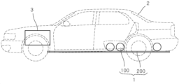
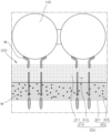
도 1은 본 발명의 일 실시예에 따른 연료전지 차량용 냉각 장치의 설치 상태를 개략적으로 나타내는 도면이다.
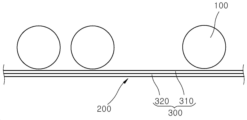
도 2는 본 발명의 일 실시예에 따른 연료전지 차량용 냉각 장치의 구성을 개략적으로 나타내는 도면이다.
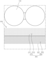
도 3은 본 발명의 일 실시예에 따른 냉각효율향상부의 구성을 개략적으로 나타내는 확대도이다.
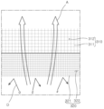
도 4 내지 도 6은 본 발명의 일 실시예에 따른 연료전지 차량용 냉각 장치의 작동 상태를 개략적으로 나타내는 작동도이다.1 is a diagram schematically illustrating an installation state of a cooling device for a fuel cell vehicle according to an embodiment of the present invention.
2 is a diagram schematically showing the configuration of a cooling device for a fuel cell vehicle according to an embodiment of the present invention.
3 is an enlarged view schematically illustrating the configuration of a cooling efficiency improving unit according to an embodiment of the present invention.
4 to 6 are operational diagrams schematically illustrating an operating state of a cooling device for a fuel cell vehicle according to an embodiment of the present invention.
이하, 첨부된 도면들을 참조하여 본 발명에 따른 연료전지 차량용 냉각 장치의 실시예를 설명한다.Hereinafter, an embodiment of a cooling device for a fuel cell vehicle according to the present invention will be described with reference to the accompanying drawings.
이 과정에서 도면에 도시된 선들의 두께나 구성요소의 크기 등은 설명의 명료성과 편의상 과장되게 도시되어 있을 수 있다. 또한, 후술되는 용어들은 본 발명에서의 기능을 고려하여 정의된 용어들로서, 이는 사용자, 운용자의 의도 또는 관례에 따라 달라질 수 있다. 그러므로 이러한 용어들에 대한 정의는 본 명세서 전반에 걸친 내용을 토대로 내려져야 할 것이다.In this process, the thickness of lines or the size of components shown in the drawings may be exaggerated for clarity and convenience of description. In addition, terms to be described later are terms defined in consideration of functions in the present invention, which may vary according to the intention or custom of a user or operator. Therefore, definitions of these terms will have to be made based on the content throughout this specification.
또한, 본 명세서에서, 어떤 부분이 다른 부분과 "연결(또는 접속)"되어 있다고 할 때, 이는 "직접적으로 연결(또는 접속)"되어 있는 경우뿐만 아니라, 그 중간에 다른 부재를 사이에 두고 "간접적으로 연결(또는 접속)"되어 있는 경우도 포함한다. 본 명세서에서, 어떤 부분이 어떤 구성요소를 "포함(또는 구비)"한다고 할 때, 이는 특별히 반대되는 기재가 없는 한 다른 구성요소를 제외하는 것이 아니라 다른 구성요소를 더 "포함(또는 구비)"할 수 있다는 것을 의미한다.In addition, in this specification, when a part is said to be “connected (or connected)” to another part, this is not only the case where it is “directly connected (or connected)”, but also “with another member in between” It also includes cases where it is indirectly connected (or connected). In this specification, when it is said that a certain part "includes (or includes)" a certain component, this does not exclude other components unless otherwise stated, but "includes (or includes)" other components. It means you can.
또한, 본 명세서 전체에 걸쳐 동일한 참조 부호는 동일한 구성 요소를 지칭할 수 있다. 동일한 참조 부호 또는 유사한 참조 부호들은 특정 도면에서 언급 또는 설명되지 않았더라도, 그 부호들은 다른 도면을 토대로 설명될 수 있다. 또한, 특정 도면에 참조 부호가 표시되지 않은 부분이 있더라도, 그 부분은 다른 도면들을 토대로 설명될 수 있다. 또한, 본 출원의 도면들에 포함된 세부 구성요소들의 개수, 형상, 크기 및 크기의 상대적인 차이 등은 이해의 편의를 위해 설정된 것으로서, 실시예들을 제한하지 않으며 다양한 형태로 구현될 수 있다.Also, like reference numerals may refer to like elements throughout this specification. Even if the same reference numerals or similar reference numerals are not mentioned or described in a particular drawing, the numerals may be described based on another drawing. In addition, even if there are parts not marked with reference numerals in specific drawings, the parts can be described based on other drawings. In addition, the number, shape, size, and relative difference of the detailed components included in the drawings of the present application are set for convenience of understanding, and may be implemented in various forms without limiting the embodiments.
도 1은 본 발명의 일 실시예에 따른 연료전지 차량용 냉각 장치의 설치 상태를 개략적으로 나타내는 도면이고, 도 2는 본 발명의 일 실시예에 따른 연료전지 차량용 냉각 장치의 구성을 개략적으로 나타내는 도면이다.1 is a diagram schematically showing an installation state of a cooling device for a fuel cell vehicle according to an embodiment of the present invention, and FIG. 2 is a diagram schematically showing a configuration of a cooling device for a fuel cell vehicle according to an embodiment of the present invention. .
도 1, 도 2를 참조하면, 본 발명의 일 실시예에 따른 연료전지 차량용 냉각 장치(1)는 연료저장탱크(100), 커버부(200), 냉각효율향상부(300)를 포함한다.1 and 2 , a
연료저장탱크(100)는 차량(2)에 설치되어 지지된다. 연료저장탱크(100)는 차량(2)에 구동력을 제공하는 연료전지부(3)로 공급되는 연료를 저장한다. 여기서 차량(2)은 수소 연료전지 차량으로 예시될 수 있고, 연료는 수소 연료전지 차량의 연료로 사용되는 수소로 예시될 수 있다. 본 발명의 일 실시예에 따른 연료저장탱크(100)는 내부에 연료를 저온 및 고압 상태로 보관할 수 있는 저장용기의 형태를 갖도록 형성될 수 있다. 연료저장탱크(100)는 플라스틱 소재로 이루어진 내부의 라이너층과 탄소복합재 소재로 이루어진 외부의 복합재층으로 구성될 수 있다. 연료저장탱크(100)는 차량(2)의 후방 하측부에 배치될 수 있다. 연료저장탱크(100)는 복수개로 구비되어 차량(2)의 길이 방향을 따라 나란하게 배치될 수 있다.The
커버부(200)는 연료저장탱크(100)의 일측에 설치되어 연료저장탱크(100)를 커버한다. 본 발명의 일 실시예에 따른 커버부(200)는 판의 형태를 갖도록 형성되어 연료전지 차량(2)의 하방에 고정된다. 커버부(200)는 상측면이 연료저장탱크(100)의 하측면과 마주보게 배치된다. 커버부(200)는 복수개로 구비되어 상호 분할된 상태로 차량(2)의 하방에 각각 고정될 수 있다. 커버부(200)는 용접 등에 의해 연료전지 차량(2)의 하방에 일체로 고정될 수 있고, 볼팅 등에 의해 연료전지 차량(2)의 하방에 착탈 가능하게 고정되는 것도 가능하다. 커버부(200)의 구체적인 형상 및 개수는 연료저장탱크(100)의 개수 및 크기 등에 따라 다양하게 설계 변경이 가능하다.The
냉각효율향상부(300)는 커버부(200)에 구비된다. 냉각효율향상부(300)는 도 2에 도시된 바와 같이 커버부(200)의 영역 전체에 걸쳐 구비되어 커버부(200)의 외관 자체를 형성할 수 있고, 커버부(200)의 영역 일부에만 구비되어 커버부(200)의 외관 일부를 형성하는 것도 가능하다. The cooling
냉각효율향상부(300)는 에칭 가공 등에 의해 복수개의 미세홀이 격자 또는 메쉬(mesh) 형태로 배열된 다공성 구조를 통해 연료저장탱크(100)의 냉각 효율을 향상시킨다. 보다 구체적으로, 냉각효율향상부(300)는 다공성 구조에 의해 차량(2)의 하방을 유동하는 공기(A)가 연료저장탱크(100)로 향해 통과되는 것을 허용함과 동시에, 노면으로부터 유입되는 흙, 먼지 등과 같은 이물질(D)이 연료저장탱크(100)로 향해 통과되는 것은 차단한다. 즉, 냉각효율향상부(300)는 커버부(200)에 통풍 성능을 부여한다. 이에 따라 냉각효율향상부(300)는 차량(2)의 하방을 유동하는 공기(A)가 연료저장탱크(100)와 직접 접촉되도록 유도함으로써 연료저장탱크(100)를 보다 신속하고 효율적으로 냉각시킬 수 있다. The cooling
또한, 냉각효율향상부(300)는 다공성 구조에 의해 연료저장탱크(100)로부터 발생되는 수분(W)을 외부로 배출시킴과 동시에 배출되는 수분(W)의 일부를 저장한다. 냉각효율향상부(300)는 저장된 수분(W)이 연료저장탱크(100) 또는 외부 환경의 열에너지에 의해 증발되도록 유도한다. 즉, 냉각효율향상부(300)는 커버부(200)에 수분 배출 성능 및 저장 성능을 부여한다. 이에 따라 냉각효율향상부(300)는 연료저장탱크(100)로부터 발생되는 수분(W)이 커버부(200)에 과다하게 고이는 것을 방지할 수 있고, 수분(W)의 증발열에 의해 연료저장탱크(100)를 보다 신속하고 효율적으로 냉각시킬 수 있다.In addition, the cooling
도 3은 본 발명의 일 실시예에 따른 냉각효율향상부의 구성을 개략적으로 나타내는 확대도이다.3 is an enlarged view schematically illustrating the configuration of a cooling efficiency improving unit according to an embodiment of the present invention.
도 3을 참조하면, 본 발명의 일 실시예에 따른 냉각효율향상부(300)는 제1냉각효율향상부재(310), 제2냉각효율향상부재(320)를 포함한다.Referring to FIG. 3 , the cooling
제1냉각효율향상부재(310)는 냉각효율향상부(300)의 일측 외관을 형성하고, 연료저장탱크(100)와 마주보게 배치된다. The first cooling
본 발명의 일 실시예에 따른 제1냉각효율향상부재(310)는 제1바디부(311), 수분배출부(312)를 포함한다.The first cooling
제1바디부(311)는 대략 판의 형태를 갖도록 형성되어 커버부(200)의 상면을 따라 배치된다. 제1바디부(311)는 상측면이 연료저장탱크(100)의 하측면과 소정 간격 이격되어 마주보게 배치된다. 제1바디부(311)는 연료저장탱크(100)와의 효율적인 열교환이 가능하도록 구리, 알루미늄 등 열전도도가 높은 재질로 구비될 수 있다. The first body portion 311 is formed to have a substantially plate shape and is disposed along the upper surface of the
수분배출부(312)는 제1바디부(311)를 관통하여 형성되고, 연료저장탱크(100)로부터 발생되는 수분(W)을 제2냉각효율향상부재(320)로 배출한다. 본 발명의 일 실시예에 따른 수분배출부(312)는 에칭 가공 등에 의해 제1바디부(311)를 격자 형태로 관통하는 복수개의 미세홀의 형태를 갖도록 형성될 수 있다. 수분배출부(312)의 단면 형상은 도 3에 도시된 사각형의 형상 이외에도 원형, 타원형, 다각형 등 다양한 형상으로 설계 변경이 가능하다. 수분배출부(312)의 단면적의 크기는 수분, 공기의 통과를 원활하게 허용할 수 있는 크기의 범위 내에서 다양하게 설계 변경이 가능하다.The
제2냉각효율향상부재(320)는 제1냉각효율향상부재(310)와 연통되고, 지면과 마주보게 배치된다. 제2냉각효율향상부재(320)의 기공률은 제1냉각효율향상부재(310)의 기공률보다 작게 형성될 수 있다. 이에 따라 제1냉각효율향상부재(310)와 제2냉각효율향상부재(320)는 상방 즉, 연료저장탱크(100)로부터 유입되는 수분(W)을 노면으로 원활하게 배출시킴과 동시에 하방, 즉 노면으로부터 유입되는 이물질(D)이 연료저장탱크(100)로 향해 통과되는 것을 차단할 수 있다.The second cooling
본 발명의 일 실시예에 따른 제2냉각효율향상부재(320)는 제2바디부(321), 수분저장부(322)를 포함한다. The second cooling
제2바디부(321)는 대략 판의 형태를 갖도록 형성되어 커버부(200)의 하면을 따라 배치된다. 제2바디부(321)는 상측면이 제1바디부(311)의 하측면에 접하도록 배치된다. 제2바디부(321)는 제1바디부(311)와 일체로 제작될 수 있고, 이와 달리 제1바디부(311)와 별물로 제작된 후 제1바디부(311)의 하측면에 용접, 볼팅, 접착제 등에 의해 고정되는 것도 가능하다. 제2바디부(321)는 하측면이 지면과 마주보게 배치되고, 지면으로부터 유입되는 이물질(D)에 간섭되어 이물질(D)이 제1바디부(311)로 향해 통과되는 것을 차단한다. 제2바디부(321)는 연료저장탱크(100)와의 효율적인 열교환이 가능하도록 구리, 알루미늄 등 열전도도가 높은 재질로 구비될 수 있다. The
수분저장부(322)는 제2바디부(321)를 관통하여 형성되고, 연료저장탱크(100)로부터 발생되는 수분(W)의 일부를 저장한다. 본 발명의 일 실시예에 따른 수분배출부(312)는 에칭 가공 등에 의해 제2바디부(321)를 격자 형태로 관통하는 복수개의 미세홀의 형태를 갖도록 형성될 수 있다. 수분저장부(322)의 단면 형상은 도 3에 도시된 사각형의 형상 이외에도 원형, 타원형, 다각형 등 다양한 형상으로 설계 변경이 가능하다. 수분저장부(322)는 단면적이 수분배출부(312)의 단면적보다 작게 형성된다. 이에 따라 수분저장부(322)는 제2냉각효율향상부재(320)의 기공률을 제1냉각효율향상부재(310)의 기공률보다 작게 형성되도록 할 수 있다. 수분저장부(322)의 구체적인 단면적의 크기는 표면 장력에 의해 액체 상태의 수분(W)의 일부를 내부에 흡착시킬 수 있는 크기의 범위 내에서 다양하게 설계 변경이 가능하다. 또한, 수분저장부(322)의 개수는 제2냉각효율향상부재(320)의 기공률이 제1냉각효율향상부재(310)의 기공률보다 커지지 않게 하는 범위 내에서 다양하게 설계 변경이 가능하다.The
이하에서는 본 발명의 일 실시예에 따른 연료전지 차량용 냉각 장치(1)의 작동을 상세하게 설명하도록 한다.Hereinafter, the operation of the
도 4 내지 도 6은 본 발명의 일 실시예에 따른 연료전지 차량용 냉각 장치의 작동 상태를 개략적으로 나타내는 작동도이다.4 to 6 are operational diagrams schematically illustrating an operating state of a cooling device for a fuel cell vehicle according to an embodiment of the present invention.
도 4를 참조하면, 차량(2)의 주행 시 또는 별도의 외력에 의해 흙, 먼지 등과 같은 이물질(D)이 커버부(200)로 유입되는 경우, 제2바디부(321)는 이물질(D)의 통과를 차단하여 이물질(D)이 연료저장탱크(100)와 직접적으로 접촉되는 것을 방지한다.Referring to FIG. 4 , when a foreign substance D such as soil or dust is introduced into the
한편, 차량(2)의 하방을 유동하는 공기(A)는 수분저장부(322) 및 수분배출부(312)를 순차적으로 거쳐 커버부(200)를 통과한다. On the other hand, the air A flowing below the
커버부(200)를 통과한 공기(A)는 연료저장탱크(100)와 접촉되고, 연료저장탱크(100)와의 열교환 작용에 의해 연료저장탱크(100)를 냉각시킨다.The air (A) passing through the
도 5를 참조하면, 외부 환경에 비해 연료저장탱크(100)의 온도가 상대적으로 낮게 유지되는 경우, 연료저장탱크(100)의 표면에는 수분(W)이 응결된다. Referring to FIG. 5 , when the temperature of the
일정량 이상 응결된 수분(W)은 자중에 의해 커버부(200)를 향해 떨어지고, 수분배출부(312)로 유입된 뒤 수분저장부(322)로 전달된다.Moisture (W) condensed over a certain amount falls toward the
수분저장부(322)로 전달된 수분(W)의 일부는 자중 및 모세관 현상에 의해 지면으로 배출된다.Some of the moisture (W) delivered to the
수분저장부(322)로 전달된 수분(W)의 나머지 일부는 제2바디부(321)에 대한 표면장력에 의해 지면으로 배출되지 않고 수분저장부(322)의 내부에 흡착되어 저장된다.The remaining part of the moisture (W) delivered to the
도 6을 참조하면, 연료저장탱크(100)의 온도가 소정 온도 이상으로 상승됨에 따라 연료저장탱크(100)로부터 발생되는 열(H)은 수분저장부(322)의 내부에 저장된 수분(W)으로 전달된다.Referring to FIG. 6, as the temperature of the
수분저장부(322)의 내부에 저장된 수분(W)은 연료저장탱크(100)로부터 발생되는 열을 흡수하며 증발되고, 연료저장탱크(100)는 수분(W)에 의해 흡수된 열에 의해 냉각된다.Moisture (W) stored inside the
본 발명은 도면에 도시된 실시예를 참고로 하여 설명되었으나, 이는 예시적인 것에 불과하며, 당해 기술이 속하는 분야에서 통상의 지식을 가진 자라면 이로부터 다양한 변형 및 균등한 타 실시예가 가능하다는 점을 이해할 것이다. The present invention has been described with reference to the embodiments shown in the drawings, but this is only exemplary, and those skilled in the art can make various modifications and equivalent other embodiments. will understand
따라서 본 발명의 기술적 보호범위는 아래의 특허청구범위에 의해서 정하여져야 할 것이다.Therefore, the technical protection scope of the present invention should be determined by the claims below.
1 : 연료전지 차량용 냉각 장치
2 : 차량
3 : 연료전지부
100 : 연료저장탱크
200 : 커버부
300 : 냉각효율향상부
310 : 제1냉각효율향상부재
311 : 제1바디부
312 : 수분배출부
320 : 제2냉각효율향상부재
321 : 제2바디부
322 : 수분저장부
A : 공기
D : 이물질
W : 수분
H : 열Reference Signs List 1: fuel cell vehicle cooling device 2: vehicle
3: fuel cell unit 100: fuel storage tank
200: cover part 300: cooling efficiency improvement part
310: first cooling efficiency improving member 311: first body part
312: water discharge unit 320: second cooling efficiency improving member
321: second body part 322: moisture storage part
A: Air D: Foreign matter
W: Moisture H: Heat
Claims (7)
상기 연료저장탱크의 일측에 설치되어 상기 연료저장탱크를 커버하는 커버부; 및
상기 커버부에 구비되고, 상기 연료저장탱크의 냉각 효율을 향상시키는 냉각효율향상부;를 포함하는 것을 특징으로 하는 연료전지 차량용 냉각 장치.
A fuel storage tank for storing fuel;
a cover unit installed on one side of the fuel storage tank to cover the fuel storage tank; and
A cooling device for a fuel cell vehicle comprising a; cooling efficiency improving unit provided in the cover unit and improving cooling efficiency of the fuel storage tank.
상기 냉각효율향상부는 차량의 하방을 유동하는 공기가 상기 연료저장탱크를 향해 통과되는 것을 허용하는 것을 특징으로 하는 연료전지 차량용 냉각 장치.
According to claim 1,
The cooling device for a fuel cell vehicle according to claim 1 , wherein the cooling efficiency improving unit allows air flowing downward of the vehicle to pass toward the fuel storage tank.
상기 냉각효율향상부는 상기 연료저장탱크로부터 발생되는 수분의 증발을 유도하는 것을 특징으로 하는 연료전지 차량용 냉각 장치.
According to claim 1,
The cooling device for a fuel cell vehicle, characterized in that the cooling efficiency improving unit induces evaporation of moisture generated from the fuel storage tank.
상기 냉각효율향상부는 다공성 구조를 갖는 것을 특징으로 하는 연료전지 차량용 냉각 장치.
According to claim 1,
The cooling efficiency improving unit has a porous structure.
상기 냉각효율향상부는,
상기 연료저장탱크와 마주보게 배치되는 제1냉각효율향상부재; 및
상기 제1냉각효율향상부재와 연통되고, 지면과 마주보게 배치되는 제2냉각효율향상부재;를 포함하는 것을 특징으로 하는 연료전지 차량용 냉각 장치.
According to claim 4,
The cooling efficiency improvement unit,
a first cooling efficiency improving member disposed to face the fuel storage tank; and
and a second cooling efficiency improving member communicating with the first cooling efficiency improving member and disposed facing the ground.
상기 제2냉각효율향상부재의 기공률은 상기 제1냉각효율향상부재의 기공률보다 작은 것을 특징으로 하는 연료전지 차량용 냉각 장치.
According to claim 5,
The second cooling efficiency improving member has a porosity smaller than that of the first cooling efficiency improving member.
제2냉각효율향상부재는,
상기 제1냉각효율향상부재와 마주보게 배치되고, 이물질의 통과를 차단하는 제2바디부; 및
상기 제2바디부를 관통하여 형성되고, 상기 연료저장탱크로부터 발생되는 수분을 저장하는 수분저장부;를 포함하는 것을 특징으로 하는 연료전지 차량용 냉각 장치.According to claim 5,
The second cooling efficiency improving member,
a second body portion disposed to face the first cooling efficiency improving member and blocking the passage of foreign substances; and
and a water storage unit formed penetrating the second body and storing water generated from the fuel storage tank.
Priority Applications (1)
| Application Number | Priority Date | Filing Date | Title |
|---|---|---|---|
| KR1020210123089A KR20230040407A (en) | 2021-09-15 | 2021-09-15 | Cooling apparatus for fuel cell vehicle |
Applications Claiming Priority (1)
| Application Number | Priority Date | Filing Date | Title |
|---|---|---|---|
| KR1020210123089A KR20230040407A (en) | 2021-09-15 | 2021-09-15 | Cooling apparatus for fuel cell vehicle |
Publications (1)
| Publication Number | Publication Date |
|---|---|
| KR20230040407A true KR20230040407A (en) | 2023-03-23 |
Family
ID=85799376
Family Applications (1)
| Application Number | Title | Priority Date | Filing Date |
|---|---|---|---|
| KR1020210123089A Pending KR20230040407A (en) | 2021-09-15 | 2021-09-15 | Cooling apparatus for fuel cell vehicle |
Country Status (1)
| Country | Link |
|---|---|
| KR (1) | KR20230040407A (en) |
-
2021
- 2021-09-15 KR KR1020210123089A patent/KR20230040407A/en active Pending
Similar Documents
| Publication | Publication Date | Title |
|---|---|---|
| US9052168B1 (en) | Electric vehicle undercarriage crumple zone | |
| JP7189112B2 (en) | freight vehicle | |
| US10547091B2 (en) | Battery device | |
| US9054402B1 (en) | Electric vehicle battery pack protection system | |
| US11837743B2 (en) | Battery with a fire protection device and motor vehicle | |
| US20060113145A1 (en) | Fuel cell vehicle | |
| CN102317612A (en) | DEVICE FOR TREATING EVAPORATED FUEl | |
| KR20080110733A (en) | Heat exchanger for energy storage | |
| KR100847722B1 (en) | Mobile body having fuel cell system | |
| US20220255161A1 (en) | Electric batteries cooling system | |
| US20220223969A1 (en) | Storage Module Having a Degassing Line | |
| DE102018202840A1 (en) | Battery system for cooling a battery and motor vehicle with battery system | |
| JP2016105365A (en) | Battery protection device of vehicle | |
| CN111971810A (en) | Multi-piece type multifunctional battery case | |
| JP2008510115A (en) | Deep refrigerant storage container | |
| US20210167440A1 (en) | Method and device for controlling the temperature of a battery assembly | |
| JP2006327325A (en) | Cooling device for fuel cell vehicle | |
| US9105886B2 (en) | Large-area demineralizer for fuel cell | |
| KR20230040407A (en) | Cooling apparatus for fuel cell vehicle | |
| US20200161677A1 (en) | Fuel cell system | |
| KR101519717B1 (en) | Heat transfer device for electronic control units | |
| JP4626342B2 (en) | Cooling device for fuel cell vehicle | |
| JP2018158595A (en) | Fuel cell vehicle | |
| KR20190009634A (en) | Apparatus for cooling of battery and battery pack including the same | |
| JP2006049200A (en) | Fuel cell system |
Legal Events
| Date | Code | Title | Description |
|---|---|---|---|
| PA0109 | Patent application |
St.27 status event code: A-0-1-A10-A12-nap-PA0109 |
|
| P11-X000 | Amendment of application requested |
St.27 status event code: A-2-2-P10-P11-nap-X000 |
|
| P13-X000 | Application amended |
St.27 status event code: A-2-2-P10-P13-nap-X000 |
|
| R15-X000 | Change to inventor requested |
St.27 status event code: A-3-3-R10-R15-oth-X000 |
|
| R16-X000 | Change to inventor recorded |
St.27 status event code: A-3-3-R10-R16-oth-X000 |
|
| R18-X000 | Changes to party contact information recorded |
St.27 status event code: A-3-3-R10-R18-oth-X000 |
|
| PG1501 | Laying open of application |
St.27 status event code: A-1-1-Q10-Q12-nap-PG1501 |
|
| A201 | Request for examination | ||
| PA0201 | Request for examination |
St.27 status event code: A-1-2-D10-D11-exm-PA0201 |
|
| D13-X000 | Search requested |
St.27 status event code: A-1-2-D10-D13-srh-X000 |
|
| D21 | Rejection of application intended |
Free format text: ST27 STATUS EVENT CODE: A-1-2-D10-D21-EXM-PE0902 (AS PROVIDED BY THE NATIONAL OFFICE) |
|
| PE0902 | Notice of grounds for rejection |
St.27 status event code: A-1-2-D10-D21-exm-PE0902 |