KR20230038760A - Heat exchangers and flue gas treatment systems - Google Patents
Heat exchangers and flue gas treatment systems Download PDFInfo
- Publication number
- KR20230038760A KR20230038760A KR1020237005242A KR20237005242A KR20230038760A KR 20230038760 A KR20230038760 A KR 20230038760A KR 1020237005242 A KR1020237005242 A KR 1020237005242A KR 20237005242 A KR20237005242 A KR 20237005242A KR 20230038760 A KR20230038760 A KR 20230038760A
- Authority
- KR
- South Korea
- Prior art keywords
- heat
- heat exchanger
- heat transfer
- opening
- gas
- Prior art date
Links
Images


Classifications
-
- F—MECHANICAL ENGINEERING; LIGHTING; HEATING; WEAPONS; BLASTING
- F22—STEAM GENERATION
- F22B—METHODS OF STEAM GENERATION; STEAM BOILERS
- F22B37/00—Component parts or details of steam boilers
- F22B37/02—Component parts or details of steam boilers applicable to more than one kind or type of steam boiler
- F22B37/06—Flue or fire tubes; Accessories therefor, e.g. fire-tube inserts
-
- F—MECHANICAL ENGINEERING; LIGHTING; HEATING; WEAPONS; BLASTING
- F23—COMBUSTION APPARATUS; COMBUSTION PROCESSES
- F23J—REMOVAL OR TREATMENT OF COMBUSTION PRODUCTS OR COMBUSTION RESIDUES; FLUES
- F23J15/00—Arrangements of devices for treating smoke or fumes
- F23J15/06—Arrangements of devices for treating smoke or fumes of coolers
-
- F—MECHANICAL ENGINEERING; LIGHTING; HEATING; WEAPONS; BLASTING
- F23—COMBUSTION APPARATUS; COMBUSTION PROCESSES
- F23J—REMOVAL OR TREATMENT OF COMBUSTION PRODUCTS OR COMBUSTION RESIDUES; FLUES
- F23J15/00—Arrangements of devices for treating smoke or fumes
- F23J15/08—Arrangements of devices for treating smoke or fumes of heaters
-
- F—MECHANICAL ENGINEERING; LIGHTING; HEATING; WEAPONS; BLASTING
- F28—HEAT EXCHANGE IN GENERAL
- F28D—HEAT-EXCHANGE APPARATUS, NOT PROVIDED FOR IN ANOTHER SUBCLASS, IN WHICH THE HEAT-EXCHANGE MEDIA DO NOT COME INTO DIRECT CONTACT
- F28D7/00—Heat-exchange apparatus having stationary tubular conduit assemblies for both heat-exchange media, the media being in contact with different sides of a conduit wall
- F28D7/16—Heat-exchange apparatus having stationary tubular conduit assemblies for both heat-exchange media, the media being in contact with different sides of a conduit wall the conduits being arranged in parallel spaced relation
-
- F—MECHANICAL ENGINEERING; LIGHTING; HEATING; WEAPONS; BLASTING
- F28—HEAT EXCHANGE IN GENERAL
- F28F—DETAILS OF HEAT-EXCHANGE AND HEAT-TRANSFER APPARATUS, OF GENERAL APPLICATION
- F28F9/00—Casings; Header boxes; Auxiliary supports for elements; Auxiliary members within casings
- F28F9/02—Header boxes; End plates
-
- F—MECHANICAL ENGINEERING; LIGHTING; HEATING; WEAPONS; BLASTING
- F28—HEAT EXCHANGE IN GENERAL
- F28G—CLEANING OF INTERNAL OR EXTERNAL SURFACES OF HEAT-EXCHANGE OR HEAT-TRANSFER CONDUITS, e.g. WATER TUBES OR BOILERS
- F28G15/00—Details
Landscapes
- Engineering & Computer Science (AREA)
- Mechanical Engineering (AREA)
- General Engineering & Computer Science (AREA)
- Physics & Mathematics (AREA)
- Thermal Sciences (AREA)
- Chemical & Material Sciences (AREA)
- Combustion & Propulsion (AREA)
- Heat-Exchange Devices With Radiators And Conduit Assemblies (AREA)
- Physical Or Chemical Processes And Apparatus (AREA)
Abstract
내부를 열매가 유동 가능한 복수의 전열관(45)과, 각 전열관(45)의 일단이 접속되고, 각 전열관(45)과의 사이에서 열매가 유동 가능한 헤더(42, 43)와, 헤더(42, 43)에 형성되어 전열관(45)의 일단(45a)을 외부로 노출시키는 개구부(42a, 43a)와, 개구부(42a, 43a)를 개폐하는 개폐부(46)를 구비한 열교환기(4)를 제공한다.A plurality of heat transfer tubes 45 through which heat can flow, one end of each heat transfer tube 45 being connected, and headers 42, 43 through which heat can flow between the heat transfer tubes 45, the header 42, Provide a heat exchanger (4) having openings (42a, 43a) formed in 43) to expose one end (45a) of the heat transfer pipe (45) to the outside, and an opening and closing part (46) for opening and closing the openings (42a, 43a). do.

Description
본 개시는, 열교환기 및 열교환기를 구비한 배연 처리 시스템에 관한 것으로, 특히, 복수의 전열관을 갖는 열교환기 및 배연 처리 시스템에 관한 것이다.The present disclosure relates to a heat exchanger and an exhaust gas treatment system provided with the heat exchanger, and more particularly, to a heat exchanger and flue gas treatment system having a plurality of heat transfer tubes.
화력 발전용의 보일러에 있어서, 보일러 내의 배기가스로부터 열을 회수하거나, 배기가스를 가열하기 위한 열교환기로서, 가스 가스 히터(Gas Gas Heater: GGH)가 알려져 있다. 가스 가스 히터에 관한 기술로서, 특허문헌 1에 기재된 기술이 알려져 있다.BACKGROUND OF THE INVENTION In a boiler for thermal power generation, a gas gas heater (GGH) is known as a heat exchanger for recovering heat from exhaust gas in the boiler or heating the exhaust gas. As a technology related to a gas gas heater, the technology described in
특허문헌 1(국제 공개공보 제2018/139669호: WO2018/139669A1)에는, 복수의 전열관(11, 12)을 갖는 열교환 번들(41)이, 전열관(11, 12)이 접속된 상하로 뻗는 기둥 형상의 헤더(42, 43)로 적층된 구성이 기재되어 있다. 특허문헌 1에 기재된 구성에서는, 헤더(42, 43)로 3단으로 적층된 열교환 번들(41)은, 바닥판(32), 배면판(33), 천판(天板)(34)으로, 상하 및 배면이 둘러싸여, 내부에 배기가스의 유로가 형성되어 있다.In Patent Document 1 (International Publication No. 2018/139669: WO2018/139669A1), a
특허문헌 1에 기재된 열교환 번들(41)에서는, 헤더(42, 43)에 복수의 전열관(11, 12)이 지지되어 있고, 전열관(11, 12)의 하나하나에 대응하여, 헤더(42, 43)의 외표면에 플러그 구멍(48)이 형성되어 있다. 플러그 구멍(48)은 통상 시는 플러그 마개로 닫혀져 있다. 그리고, 복수의 전열관(11, 12) 내에서, 고장나서 열매(熱媒)가 누출되는 전열관(11, 12)이 발생한 경우에는, 플러그 마개를 분리하고, 플러그 구멍(48)으로부터 폐지(閉止) 마개를 삽입하며, 고장난 전열관(11, 12)의 단부(열매의 출입구)에 마개를 덮고 있었다(예를 들면, 일본 공개특허공보 2015-036614호 등 참조).In the
구체적으로 마개를 덮는 수순으로서는, 이하의 (1), (2)가 행해진다.Specifically, as a procedure for covering the stopper, the following (1) and (2) are performed.
(1) 폐지 마개를 봉 형상의 지그의 선단에 장착하고, 고장난 전열관(11, 12)에 대응하는 위치의 플러그 구멍(48)을 통하여 지그 및 폐지 마개를 삽입하며, 전열관(11, 12)의 출입구에 폐지 마개를 압압한다.(1) A waste paper stopper is attached to the tip of a rod-shaped jig, and the jig and a waste paper stopper are inserted through the plug hole 48 at a position corresponding to the failed
(2) 폐지 마개를 삽입한 플러그 구멍(48)의 옆의 플러그 구멍(48)을 통하여 용접용의 기재(機材)를 삽입하여, 폐지 마개를 전열관(11, 12)의 출입구에 용접한다.(2) A base material for welding is inserted through the plug hole 48 next to the plug hole 48 into which the waste plug is inserted, and the waste plug is welded to the entrance and exit of the
특허문헌 1에 기재된 구성에서는, 수순 (1)에서 폐지 마개를 삽입할 때에, 지그를 삽입하고 있는 플러그 구멍을 통하여, 육안으로 전열관의 출입구를 확인하고 있어, 작업성이 나쁘고, 작업에 시간이 걸리는 문제가 있다. 또, 수순 (2)에서 용접을 행할 때에도, 용접하는 위치를 육안으로 확인하는 데에, 지그가 삽입되어 있는 플러그 구멍이나, 용접용의 기재가 삽입되어 있는 플러그 구멍으로 확인하고 있어, 작업성이 나쁘고, 작업 시간이 길어지는 문제가 있다. 그 이외의 플러그 구멍을 사용하면, 원근감이 있기 때문에 작업에 숙련을 필요로 하고, 익숙해지기까지 시간이 걸리는 문제가 있다.In the configuration described in
본 개시는, 고장난 전열관을 폐지하는 작업의 작업성을 향상시키는 것을 기술적 과제로 한다.This disclosure makes it a technical subject to improve the workability of the work of abolishing a failed heat exchanger tube.
상기 본 개시의 과제는, 하기의 구성을 채용함으로써 달성할 수 있다.The subject of the present disclosure can be achieved by adopting the following configuration.
본 개시의 열교환기는,The heat exchanger of the present disclosure,
내부를 열매가 유동 가능한 복수의 전열관과,A plurality of heat transfer pipes through which the heat can flow;
상기 각 전열관의 일단이 접속되고, 상기 각 전열관과의 사이에서 열매가 유동 가능한 헤더와,A header to which one end of each of the heat transfer tubes is connected, and a heat medium can flow between the headers and each of the heat transfer tubes;
상기 헤더에 형성되어 상기 전열관의 일단을 외부로 노출시키는 개구부와,An opening formed in the header to expose one end of the heat transfer pipe to the outside;
상기 개구부를 개폐하는 개폐부를 구비한 것을 특징으로 한다.It is characterized in that it is provided with an opening and closing part for opening and closing the opening.
상기에 기재된 열교환기에 있어서,In the heat exchanger described above,
모든 상기 전열관의 일단을 외부로 노출 가능한 하나의 상기 개구부와,One of the openings capable of exposing ends of all the heat transfer pipes to the outside;
하나의 상기 개구부에 대응하여 배치된 하나의 상기 개폐부를 구비한 것을 특징으로 한다.It is characterized in that it includes one opening and closing part disposed to correspond to one of the openings.
상기에 기재된 열교환기에 있어서,In the heat exchanger described above,
상기 개구부에 대하여 착탈 가능하게 지지된 상기 개폐부를 구비한 것을 특징으로 한다.It is characterized in that the opening/closing portion detachably supported with respect to the opening portion is provided.
본 개시의 배연 처리 시스템은,The flue gas treatment system of the present disclosure,
연료가 연소되는 보일러와,A boiler in which fuel is burned;
연료가 연소하여 발생한 가스의 유로 중에 배치되고, 가스와의 사이에서 열교환을 행하는 상기의 어느 하나에 기재된 열교환기를 구비한 것을 특징으로 한다.It is characterized by comprising the heat exchanger according to any one of the above, disposed in a flow path of a gas generated by burning fuel and exchanging heat with the gas.
본 개시의 열교환기에 의하면, 개폐부에서 개구부를 개방하여 전열관의 일단을 외부로 노출시킴으로써, 고장난 전열관을 폐지하는 작업의 작업성을 향상시킬 수 있다.According to the heat exchanger of the present disclosure, by opening an opening in the opening/closing portion to expose one end of the heat exchanger tube to the outside, it is possible to improve the workability of closing the failed heat exchanger tube.
본 개시에 의하면, 모든 전열관의 일단을 외부로 노출 가능한 하나의 개구부와, 하나의 개구부에 대응하여 배치된 하나의 개폐부를 구비함으로써, 복수의 개구부나 개폐부를 갖는 경우에 비하여, 개폐 작업이 용이해져 작업성을 향상시킬 수 있다.According to the present disclosure, by including one opening capable of exposing one end of all the heat transfer tubes to the outside and one opening/closing part disposed corresponding to the one opening, the opening/closing operation becomes easier compared to the case of having a plurality of openings or opening/closing parts. workability can be improved.
본 개시에 의하면, 슬라이드 가능한 개폐부나 힌지로 회전 가능한 개폐부의 경우에 비하여, 개폐부가 분리 가능한 점에서, 개구부가 개방된 상태에서 개폐부가 작업의 방해가 되는 것을 억제할 수 있다.According to the present disclosure, compared to the case of a slideable opening and closing portion or a hinge-rotatable opening and closing portion, since the opening and closing portion is detachable, it is possible to prevent the opening and closing portion from interfering with work in an open state.
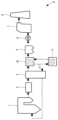
도 1은 본 개시의 실시예 1의 열교환기를 포함하는 배연 처리 시스템의 설명도이다.
도 2는 본 개시의 실시예 1의 열교환기의 본체의 설명도이다.
도 3은 도 2의 열교환기의 분해도이다.
도 4는 실시예의 열교환기를 구성하는 번들의 설명도이다.
도 5는 도 4에 나타내는 번들에 있어서 개폐부를 분리한 상태의 설명도이며, 도 5의 (A)는 사시도, 도 5의 (B)는 요부(要部) 단면도이다.
도 6은 실시예의 볼트 고정 부분의 설명도이며, 도 6의 (A)는 캡 너트의 설명도, 도 6의 (B)는 너트가 매립된 형태의 설명도이다.
도 7은 본 개시의 실시예 2의 열교환기를 포함하는 배연 처리 시스템의 설명도이다.
도 8은 본 개시의 실시예 3의 GGH 열회수기의 단면도이다.
도 9는 GGH 열회수기에 있어서의 전열관의 마모량과 배기가스의 가스 유속과 배기가스에 포함되는 더스트 농도의 관계를 나타내는 그래프이다.
도 10은 본 개시의 실시예 3의 GGH 재가열기의 단면도이다.
도 11은 GGH 열회수기 및 GGH 재가열기가 갖는 핀 장착 전열관을 상방에서 본 도이다.1 is an explanatory diagram of a flue gas treatment system including a heat exchanger according to Example 1 of the present disclosure.
2 is an explanatory view of the main body of the heat exchanger of Example 1 of the present disclosure.
3 is an exploded view of the heat exchanger of FIG. 2;
4 is an explanatory diagram of a bundle constituting the heat exchanger of the embodiment.
Fig. 5 is an explanatory view of the bundle shown in Fig. 4 in a state where the opening/closing part is removed, Fig. 5(A) is a perspective view, and Fig. 5(B) is a main part sectional view.
6 is an explanatory view of a bolt fixing part in the embodiment, FIG. 6(A) is an explanatory view of a cap nut, and FIG. 6(B) is an explanatory view of a state in which a nut is embedded.
7 is an explanatory diagram of a flue gas treatment system including a heat exchanger according to Example 2 of the present disclosure.
8 is a cross-sectional view of the GGH heat recovery device according to Example 3 of the present disclosure.
Fig. 9 is a graph showing the relationship between the amount of abrasion of heat transfer tubes in the GGH heat recovery machine, the gas flow rate of exhaust gas, and the dust concentration contained in exhaust gas.
10 is a cross-sectional view of the GGH reheater of Example 3 of the present disclosure.
Fig. 11 is a top view of finned heat transfer pipes included in the GGH heat recovery device and the GGH reheater.
다음으로 도면을 참조하면서, 본 개시의 실시형태의 구체예로서의 실시예를 설명하지만, 본 개시는 이하의 실시예에 한정되는 것은 아니다.Next, while referring to drawings, Examples as specific examples of the embodiments of the present disclosure will be described, but the present disclosure is not limited to the following examples.
또한, 이하의 도면을 사용한 설명에 있어서, 이해의 용이를 위하여 설명에 필요한 부재 이외의 도시는 적절히 생략되어 있다.In addition, in the description using the following drawings, illustration other than members necessary for explanation is omitted appropriately for ease of understanding.
〔실시예 1〕[Example 1]
도 1은 본 개시의 열교환기를 포함하는 배연 처리 시스템의 설명도이다.1 is an explanatory diagram of a flue gas treatment system including a heat exchanger of the present disclosure.
도 1에 있어서, 실시예 1의 열교환기가 적용된 배연 처리 시스템(플랜트)(S)에서는, 보일러(1)로부터의 배기가스가 탈질 장치(2)에 도입되고, 배기가스 중의 질소 산화물이 제거된 후, 공기 예열기(A/H)(3)에 있어서 보일러(1)로의 연소용 공기와 열교환된다. 다음으로, 배기가스는, 가스 가스 열교환기의 일례로서의 GGH 열회수기(4)에 도입되어 열교환(열회수)이 행해진다. GGH 열회수기(4)를 통과하여 가스 온도가 저하된 배기가스는, 가스 중의 매진(煤塵)의 공기 저항값이 저하된 상태에서 집진 장치(EP: Electrostatic Precipitator)(5)에 도입되고, 배기가스 중의 매진의 대부분이 제거된다. 그 후, 배기가스는 팬(6)에 의하여 승압되고, 습식 배연 탈황 장치(FGD: Flue Gas Desulfurization)(7)에 도입되며, 기액 접촉에 의하여 배기가스 중의 황산화물 및 매진의 일부가 제거된다. 습식 배연 탈황 장치(7)에 있어서, 포화 가스 온도까지 냉각된 배기가스는, GGH 열회수기(4)로 회수된 열을 이용하여, 가스 가스 열교환기의 일례로서의 GGH 재가열기(8)에 의하여 승온(열교환, 재가열)된다. GGH 재가열기(8)를 통과한 배기가스는 굴뚝(9)에 의하여 배출된다.1, in the exhaust gas treatment system (plant) S to which the heat exchanger of Example 1 is applied, after the exhaust gas from the
도 2는 본 개시의 실시예 1의 열교환기의 본체의 설명도이다.2 is an explanatory view of the main body of the heat exchanger of Example 1 of the present disclosure.
도 3은 도 2의 열교환기의 본체의 분해도이다.Figure 3 is an exploded view of the body of the heat exchanger of Figure 2;
도 4는 실시예의 열교환기를 구성하는 번들의 설명도이다.4 is an explanatory diagram of a bundle constituting the heat exchanger of the embodiment.
도 2, 도 3에 있어서, GGH 열회수기(4)는, 케이스의 일례로서의 하우징(31)을 갖는다. 하우징(31)은, 배면 커버의 일례로서의 판상의 배면판(33)과, 상부 커버의 일례로서의 판상의 천판(34)을 갖는다. 하우징(31)의 전부(前部)에는, 상하 방향으로 뻗는 번들 간 커버(35)가 지지되어 있다. 번들 간 커버(35)는, 상하 방향(중력 방향)으로 뻗어 있고, 좌우 방향(배기가스(배연)가 흐르는 방향)으로 미리 설정된 간격을 두고 복수 배치되어 있다. 하우징(31)의 내부에는, 열교환 번들(41)이 복수 수용된다.2 and 3, the GGH
도 2-도 4에 있어서, 각 열교환 번들(41)은, 제1 부착부의 일례로서의 제1 헤더(42)와, 제2 부착부의 일례로서의 제2 헤더(43)를 갖는다. 실시예 1의 제1 헤더(42) 및 제2 헤더(43)는, 상하 방향으로 뻗는 기둥 형상으로 형성되어 있다. 각 헤더(42, 43)는, 내부가 중공 또한 상단 및 하단이 폐색된 형상으로 형성되어 있고, 내부에 유동 가능한 공간이 형성되어 있다. 또, 각 헤더(42, 43)에는, 좌우 방향으로 돌출되는 장착 플레이트(44)가 지지되어 있다.2 to 4, each
각 헤더(42, 43)의 후면에는, 후방으로 뻗는 전열관(45)이 지지되어 있다. 전열관(45)은, 하우징(31)의 내부에서 후단 또는 전단에서 만곡되어 복수 회전 후 방향으로 왕복하도록 구성되어 있다. 또한, 각 헤더(42, 43)에는, 상하 방향으로 간격을 두고 복수의 전열관(45)이 지지되어 있다. 각 전열관(45)의 양단은, 헤더(42, 43)에 지지되어 있고, 헤더(42, 43)로부터 각 전열관(45)에 열매가 입출 가능하게 구성되어 있다.On the rear surface of each
각 전열관(45)은, 전후 방향의 중앙부에 있어서, 서포트 부재(47)로 지지되어 있다. 서포트 부재(47)는, 판에, 전열관(45)이 통과하는 구멍이 복수 형성된 형상으로 형성되어 있다. 따라서, 전열관(45)이, 헤더(42, 43)만으로 외팔보 상태로 지지되어 있지 않고, 헤더(42, 43)와 서포트 부재(47)로 지지되어 있다. 또한, 서포트 부재(47)는, 전후 방향 및 좌우 방향으로 하나를 도시하고 있지만, 전열관(45)의 길이에 따라, 전후 방향으로 복수 매 마련하거나, 좌우 방향으로 복수 매 마련하는 것도 가능하다.Each
도 5는 도 4에 나타내는 번들에 있어서 개폐부를 분리한 상태의 설명도이며, 도 5의 (A)는 사시도, 도 5의 (B)는 요부 단면도이다.Fig. 5 is an explanatory view of the bundle shown in Fig. 4 in a state where the opening/closing parts are separated, Fig. 5(A) is a perspective view and Fig. 5(B) is a main part sectional view.
도 5에 있어서, 각 헤더(42, 43)의 전부에는, 개구부(42a, 43a)가 형성되어 있다. 실시예의 개구부(42a, 43a)는, 헤더(42, 43)를 따라 상하 방향으로 뻗어 있고, 모든 전열관(45)의 단부(열매의 출입구)(45a)를 외부로 노출시키는 것이 가능한 크기로 형성되어 있다.In FIG. 5 ,
각 개구부(42a, 43a)에는, 개폐부의 일례로서의 개폐 커버(46)가 지지되어 있다. 실시예의 개폐 커버(46)는, 반원통상의 커버 본체(46a)와, 커버 본체(46a)의 좌우 양단으로부터 외측으로 돌출된 판상의 고정부(46b)를 갖는다. 개폐 커버(46)는, 개구부(42a, 43a)의 전체 영역을 폐색 가능한 길이로 형성되어 있다. 또, 개폐 커버(46)는, 고정부(46b)가 장착 플레이트(44)에 볼트 고정으로 고정되어 있다. 따라서, 볼트(46c)를 분리함으로써, 개폐 커버(46)는 헤더(42, 43)에 대하여 착탈 가능하게 구성되어 있다. 또한, 개폐 커버(46)의 고정 방법은, 볼트 고정에 한정되지 않고, 나사를 사용하는 것이 가능하며, 용이하게 절단할 수 있도록 부분적인 용접을 하는 것도 불가능하지는 않다.An opening/
개폐 커버(46)에는, 착탈 작업 시에, 작업자가 잡기 위한 손잡이를 마련하는 것이 바람직하지만, 마련하지 않은 구성으로 하는 것도 가능하다. 손잡이를 마련하는 경우에는, 개폐 커버(46)를 상방으로부터 매달기 위한 손잡이나, 개폐 커버(46)를 전후 방향으로 이동시키기 위한 손잡이와 같이 복수의 손잡이를 마련하는 것이 바람직하다.It is preferable to provide the opening/
도 6은 실시예의 볼트 고정 부분의 설명도이며, 도 6의 (A)는 캡 너트의 설명도, 도 6의 (B)는 너트가 매립된 형태의 설명도이다.6 is an explanatory view of a bolt fixing part in the embodiment, FIG. 6(A) is an explanatory view of a cap nut, and FIG. 6(B) is an explanatory view of a state in which a nut is embedded.
도 6에 있어서, 실시예의 개폐 커버(46)를 볼트 고정하기 위하여, 장착 플레이트(44)에는, 볼트(46c)가 나사 결합되는 너트(44a, 44a')가 배치되어 있다. 너트는, 도 6의 (A)에 나타내는 바와 같이, 너트(44a)를 장착 플레이트(44)에 고정한 형태로 하는 것도 가능하고, 도 6의 (B)에 나타내는 바와 같이, 장착 플레이트(44)의 두께를 두껍게 하여 장착 플레이트(44)에 너트(44a')가 매립된 형태로 하는 것도 가능하다.In Fig. 6, nuts 44a and 44a' to which
또한, 실시예에서는, 개구부(42a, 43a)의 외연(外緣)을 따라, 밀봉 부재의 일례로서의 시일(SL)이 배치되어 있다. 따라서, 개폐 커버(46)가 헤더(42, 43)에 장착된 상태에서는, 경계 부분이 시일(SL)로 막힌다. 따라서, 헤더(42, 43) 내의 열매가 외부로 누출되는 것이 억제된다.Further, in the embodiment, a seal SL as an example of a sealing member is disposed along the outer periphery of the
도 2~도 5에 있어서, 각 헤더(42, 43)의 사이에는, 접속 부재의 일례로서의 케이싱판(49)이 착탈 가능하게 지지되어 있다. 케이싱판(49)은, 헤더(42, 43)의 상하 방향의 높이에 대응하는 높이를 갖는다. 케이싱판(49)은, 장착 플레이트(44)에 도시하지 않는 볼트에 의하여 착탈 가능하게 지지되어 있다. 케이싱판(49)이 장착된 경우에는, 헤더(42, 43)가 접속된다. 따라서, 케이싱판(49)이 장착된 경우는, 헤더(42, 43), 전열관(45)이 높은 강성을 갖는 상태에서 일체화됨과 함께, 헤더(42, 43)의 사이부터 배기가스가 누출되는 것도 억제된다.2-5, between each
상기 부호 42~49를 붙인 부재에 의하여, 실시예 1의 열교환 번들(41)이 구성되어 있다. 열교환 번들(41)은, 이른바 하나의 유닛으로서, 하우징(31)에 수납 가능하게 구성되어 있다. 그리고, 열교환 번들(41)이 하우징(31)에 수납된 상태에서는, 배면판(33), 천판(34), 번들 간 커버(35), 헤더(42, 43), 케이싱판(49)이나 바닥면으로 둘러싸인 내측에, 배기가스가 흐르는 배기가스로가 구성된다. 그리고, 배기가스로 내에 전열관(45)이 배치되어 있고, 배기가스로를 흐르는 배기가스와의 사이에 열교환이 가능하게 구성되어 있다.The
도 2에 있어서, 실시예 1의 GGH 열회수기(4)에서는, 배기가스가 흐르는 방향에 대하여, 상류, 중류, 하류로 나란히 3열 배치됨과 함께, 상류, 중류, 하류의 각 열에는, 상하 방향으로 3단의 열교환 번들(41)이 적층되어 있다. 또한, 중단의 열교환 번들(41)은, 헤더(42, 43)의 하단이, 하단의 열교환 번들(41)의 헤더(42, 43)의 상단에 적층되어 있다. 동일하게, 상단의 열교환 번들(41)은, 헤더(42, 43)의 하단이, 중단의 열교환 번들(41)의 헤더(42, 43)의 상단에 적층되어 있다.In Fig. 2, in the GGH
또한, GGH 재가열기(8)는, GGH 열회수기(4)와 동일하게 구성되어 있으므로, 도시 및 상세한 설명은 생략한다.In addition, since the
(실시예 1의 작용)(Action of Example 1)
상기 구성을 구비한 실시예 1의 배연 처리 시스템(S)에서는, 복수의 전열관(45) 내에서, 부식 등으로 고장나서 열매가 누출된 전열관(45)이 발생한 경우, 고장난 전열관(45)의 단부(45a)에 폐지 마개(51)를 박아 넣는 작업을 행한다. 폐지 마개(51)를 박아 넣는 경우, 먼저, 열교환 번들(41)로의 열매의 유입을 정지하고, 전열관(45)의 열매를 발출한다. 다음으로, 헤더(42, 43)의 온도가 저하된 후에, 헤더(42, 43)의 개폐 커버(46)를 분리한다. 그리고, 개방된 개구부(42a, 43a)를 통하여, 고장난 전열관(45)의 단부(45a)에 폐지 마개(51)를 박아 넣고, 용접한다. 그리고, 개폐 커버(46)를 장착하고, 열매를 열교환 번들(41)에 유입시킨다.In the flue gas treatment system S of Example 1 having the above configuration, when a
따라서, 실시예의 열교환 번들(41)에서는, 폐지 마개(51)로 전열관(45)의 단부(45a)를 막는 작업 시에, 특허문헌 1의 플러그 구멍과는 달리, 크게 개방된 개구부(42a, 43a)를 통하여 작업을 행하는 것이 가능하다. 따라서, 플러그 구멍을 통하여 육안으로 보고 있던 종래의 구성에 비하여, 개구부(42a, 43a)를 통하여, 전열관(45)의 단부(45a)의 육안으로의 확인도 용이하고, 폐지 마개(51)를 용접하는 작업도 용이해진다. 따라서, 실시예의 열교환 번들(41)에서는, 고장난 전열관(45)을 폐지하는 작업의 작업성을 향상시킬 수 있고, 작업의 시간도 단축 가능하다.Therefore, in the
특히, 실시예에서는, 하나의 개폐 커버(46)로, 모든 전열관(45)의 단부(45a)가 개방(노출), 폐색 가능하다. 따라서, 전열관(45)마다 개별의 커버를 개폐하는 경우에 비하여, 작업도 용이하다.In particular, in the embodiment, with one opening/closing
또, 실시예에서는, 개구부(42a, 43a)와 개폐 커버(46)의 사이는 시일(SL)로 밀폐되어 있다. 특허문헌 1에 기재된 종래의 구성에서는, 열교환 번들(41)의 사용 시(열교환 시)에는, 다수의 플러그 구멍에 각각 플러그 마개가 장착되어 있었지만, 플러그 마개의 수가 다수가 되기 때문에, 다수의 플러그 마개가 모두 완전하게 밀폐되어 있는 상황은 현실적으로는 실현하기 어렵고, 플러그 마개의 부분을 통하여 열매가 누출되는 것이 문제가 되고 있었다. 이에 대하여, 실시예에서는, 플러그 마개 자체가 마련되어 있지 않고, 또, 하나의 개구부(42a, 43a)와 하나의 개폐 커버(46)의 사이의 시일(SL)로 밀폐되어 있으며, 밀폐 상태의 관리가 종래의 구성에 비하여 용이하게 되어 있다.In the embodiment, the gap between the
또, 열교환 번들(41)은, 사용에 따라, 헤더(42, 43)의 바닥부에 진흙상의 드레인이 퇴적되어 간다. 종래의 플러그 구멍의 구성에서는 드레인의 배출이 곤란했다. 이에 대하여, 실시예에서는 개구부(42a, 43a)가 크게 개방된다. 따라서, 개방된 개구부(42a, 43a)를 통하여 드레인의 배출이나 긁어내는 것도 가능해진다.Further, as the
〔실시예 2〕[Example 2]
다음으로, 본 개시의 실시예 2에 대하여 설명한다. 실시예 2는, 실시예 1의 변형예이며, 이하에서 특별히 설명하는 경우를 제외하고, 실시예 1과 동일한 것으로 한다. 도 7은 본 개시의 실시예 2의 열교환기를 포함하는 배연 처리 시스템의 설명도이다.Next, Example 2 of the present disclosure will be described. Example 2 is a modified example of Example 1, and is the same as Example 1 except for the cases specifically described below. 7 is an explanatory diagram of a flue gas treatment system including a heat exchanger according to Example 2 of the present disclosure.
실시예 1의 배연 처리 시스템(S)은, 습식 배연 탈황 장치(7)에 있어서, 포화 가스 온도까지 냉각된 배기가스를, GGH 열회수기(4)로 회수된 열을 이용하여, GGH 재가열기(8)에 의하여 승온시키는 것이었다. 그에 대하여, 실시예 2의 배연 처리 시스템(S)은, 공기 예열기(3)를 통과한 배기가스의 열을 회수하고, 회수한 열을 이용하여 보일러(1)로 공급되는 물(보일러 급수)을 승온시키는 것이다.In the flue gas treatment system S of Example 1, in the wet flue gas desulfurization device 7, the exhaust gas cooled to the saturated gas temperature is recovered by the GGH
도 7에 나타내는 바와 같이, 실시예 2의 배연 처리 시스템(S)은, 열회수기(열교환기)(10)와, 급수 가열기(열교환기)(11)를 구비한다. 열회수기(10)는, 공기 예열기(3)를 통과한 배기가스의 열을, 내부를 유통하는 열매에 전달함으로써, 배기가스의 열을 회수하는 장치이다. 열회수기(10)에 의하여 가열된 열매는, 급수 가열기(11)에 공급된다.As shown in FIG. 7 , the flue gas treatment system S of Example 2 includes a heat recovery device (heat exchanger) 10 and a feed water heater (heat exchanger) 11 . The
급수 가열기(11)는, 열회수기(10)로 회수된 열을 이용하여, 보일러(1)로 공급되는 물을 가열하는 장치이다. 급수 가열기(11)는, 열회수기(10)로부터 공급되는 열매와 보일러(1)로 공급되는 물의 열교환을 행하여, 보일러(1)로 공급되는 물을 가열한다. 급수 가열기(11)는, 보일러(1)로 공급되는 물을 가열하는 열원으로서 이용한 열매를, 열회수기(10)에 공급한다.The
〔실시예 3〕[Example 3]
본 개시의 실시예 3에 대하여 설명한다. 실시예 3은, 실시예 1의 변형예이며, 이하에서 특별히 설명하는 경우를 제외하고, 실시예 1과 동일한 것으로 한다. 도 8은, 본 개시의 실시예 3의 GGH 열회수기(4)의 단면도이다. 도 8에 나타내는 화살표는, 공기 예열기(3)로부터 GGH 열회수기(4)에 유입되는 배기가스의 흐름 방향을 나타낸다.Example 3 of the present disclosure will be described. Example 3 is a modified example of Example 1, and is the same as Example 1 except for the cases specifically described below. 8 is a cross-sectional view of the GGH
도 8에 나타내는 바와 같이, 본 실시예의 GGH 열회수기(4)는, 배기가스의 흐름 방향의 상류 측으로부터 하류 측을 향하여 배치되는 3개의 열교환 번들(41)을 갖는다. 배기가스의 흐름 방향의 가장 상류 측에 열교환 번들(41A)이 배치되고, 배기가스의 흐름 방향의 가장 하류 측에 열교환 번들(41C)이 배치된다. 열교환 번들(41A)과 열교환 번들(41C)의 사이에 열교환 번들(41B)이 배치된다.As shown in Fig. 8, the GGH
도 8에 나타내는 전열관(45)은, 관체(45A)와, 관체(45A)에 장착된 핀(45B)을 갖는다. 도 8에 나타내는 바와 같이, 열교환 번들(41A, 41B, 41C)을 구성하는 모든 전열관(45)은, 관체(45A)와, 핀(45B)을 갖는다.The
도 8에 나타내는 바와 같이, 복수의 전열관(45)은, 복수의 전열관(45)을 통과하는 배기가스의 흐름 방향을 따라, 일정한 간격(P1)을 두고 배치된다. 또, 복수의 전열관(45)은, 복수의 전열관(45)을 통과하는 배기가스의 흐름 방향에 대하여 직교하는 연직 방향(VD)을 따라 일정한 간격(P1)을 두고 배치되어 있다.As shown in FIG. 8 , the plurality of
도 8에 나타내는 바와 같이, 복수의 전열관(45)은, 배기가스의 흐름 방향에 인접하는 한 쌍의 전열관(45)의 연직 방향(VD)의 위치가 동일 위치가 되도록 배열되어 있다. 즉, 복수의 전열관(45)은, 정방 배열이 되도록 배치되어 있다.As shown in FIG. 8 , the plurality of
정방 배열에서는, 전열관(45)의 최상류 부분에 배기가스가 접촉하지만, 그것보다 하류 측의 부분에서는, 배기가스의 흐름 방향에 대하여 최상류 부분에 가려지는 형태로 배기가스와의 접촉이 저감됨과 함께, 접촉이 저감되는 만큼, 배기가스는 흐르기 쉽다. GGH 열회수기(4)에서는, 열교환 번들(41A, 41B, 41C)을 구성하는 모든 전열관(45)을 정방 배열로 함으로써, 애시 이로전(ash erosion)이 저감된다.In the square arrangement, the exhaust gas contacts the most upstream portion of the
도 8에 나타내는 복수의 열교환 번들(41A, 41B, 41C)은, 전열관(45)의 관간 유속이 10m/s 이하가 되도록 배열되어 있다. 여기에서, 전열관(45)의 관간 유속이란, 배기가스의 흐름 방향에 대하여 직교하는 연직 방향(VD)에 인접하는 한 쌍의 전열관(45)의 사이를 통과하는 배기가스의 유속을 말한다. 보다 구체적으로는, 관간 유속은, 도 8에 나타내는 1단째의 전열관(45)의 중심축(L1)의 위치에 있어서, 열교환 번들(41A)의 연직 방향(VD)의 단면적으로부터 전열관(45)의 연직 방향(VD)의 단면적의 합계를 뺀 단면적 영역을 통과하는 배기가스의 유속을 말한다.The plurality of
도 8에 나타내는 복수의 열교환 번들(41A, 41B, 41C)에 있어서, 전열관(45)의 관간 유속이 10m/s 이하가 되도록 하고 있는 것은, 전열관(45)의 마모를 억제하기 위함이다. GGH 열회수기(4)에서는, 일반적으로, 약 0.1mm/년 이하의 전열관(45)의 마모 속도인 것이 바람직하다.In the plurality of
본 발명자들은, 집진 장치(5)의 상류 측에 배치되는 GGH 열회수기(4)의 전열관(45)의 마모량과 배기가스의 유속의 관계를 검토했다. 그 결과, 도 9에 나타내는 계측 결과를 얻었다. 도 9는, GGH 열회수기(4)에 있어서의 전열관(45)의 마모량과 배기가스의 가스 유속과 배기가스에 포함되는 더스트 농도의 관계를 나타내는 그래프이다. 도 9에 있어서, A는 0.1mm/년으로 설정한 마모 한계선이다.The inventors of the present invention examined the relationship between the abrasion amount of the
도 9에 나타내는 바와 같이, 본 발명자들은, 배기가스의 가스 유속이 배기가스 중의 더스트 농도의 다소에 관계없이, 가스 유속이 10m/s보다 높은 경우에 전열관(45)의 마모량이 급격하게 증가하는 현상을 알아냈다. 그 때문에, 본 실시예에서는, 복수의 열교환 번들(41A, 41B, 41C)에 있어서, 전열관(45)의 관간 유속이 10m/s 이하가 되도록 하고 있다.As shown in Fig. 9, the present inventors have a phenomenon in which the wear amount of the
도 10은, 본 개시의 실시예 3의 GGH 재가열기(8)의 단면도이다. 도 10에 나타내는 화살표는, 습식 배연 탈황 장치(7)로부터 GGH 재가열기(8)에 유입되는 배기가스의 흐름 방향을 나타낸다.10 is a cross-sectional view of the
도 10에 나타내는 바와 같이, 본 실시예의 GGH 재가열기(8)는, 배기가스의 흐름 방향의 상류 측으로부터 하류 측을 향하여 배치되는 3개의 열교환 번들(41)을 갖는다. 배기가스의 흐름 방향의 가장 상류 측에 열교환 번들(41D)이 배치되고, 배기가스의 흐름 방향의 가장 하류 측에 열교환 번들(41F)이 배치된다. 열교환 번들(41D)과 열교환 번들(41F)의 사이에 열교환 번들(41E)이 배치된다.As shown in Fig. 10, the
도 10에 나타내는 열교환 번들(41E, 41F)을 구성하는 전열관(45)은, 관체(45A)와, 관체(45A)에 장착되는 핀(45B)을 갖는다. 도 10에 나타내는 열교환 번들(41D)을 구성하는 전열관(45)은, 관체(45A)를 갖지만, 핀(45B)이 장착되어 있지 않은 나관(裸管)이다. 열교환 번들(41D)을 구성하는 전열관(45)을 핀(45B)이 없는 나관으로 하고 있는 것은, 습식 배연 탈황 장치(7)로부터 도입되는 미스트가 전열관(45)에 부착됨으로써 부식되는 트러블을 억제하기 위함이다.The
도 10에 나타내는 바와 같이, 복수의 전열관(45)은, 복수의 전열관(45)을 통과하는 배기가스의 흐름 방향을 따라, 일정한 간격(P2)을 두고 배치된다. 또, 복수의 전열관(45)은, 복수의 전열관(45)을 통과하는 배기가스의 흐름 방향에 대하여 직교하는 연직 방향(VD)을 따라 일정한 간격(P2)을 두고 배치되어 있다.As shown in FIG. 10 , the plurality of
도 10에 나타내는 바와 같이, 열교환 번들(41E, 41F)을 구성하는 복수의 전열관(45)은, 배기가스의 흐름 방향에 인접하는 한 쌍의 전열관(45)의 연직 방향(VD)의 위치가 동일 위치가 되도록 배열되어 있다. 즉, 복수의 전열관(45)은, 정방 배열이 되도록 배치되어 있다. GGH 재가열기(8)에서는, 열교환 번들(41E, 41F)을 구성하는 전열관(45)을 정방 배열로 함으로써, 애시 이로전이 저감된다.As shown in Fig. 10, in the plurality of
한편, 도 10에 나타내는 바와 같이, 열교환 번들(41D)을 구성하는 복수의 전열관(45)은, 배기가스의 흐름 방향에 인접하는 한 쌍의 전열관(45)의 연직 방향(VD)의 위치가 인접하는 한 쌍의 전열관(45)의 중간의 위치가 되도록 배열되어 있다. 즉, 복수의 전열관(45)은, 배기가스의 흐름 방향에 인접하는 한 쌍의 전열관(45)의 연직 방향(VD)의 위치가 상이한 지그재그 배열이 되도록 배치되어 있다.On the other hand, as shown in FIG. 10 , in the plurality of
지그재그 배열에서는, 전열관(45)의 하류 측의 부분이 상류 측의 부분에 가려지기 어렵기 때문에, 배기가스와의 접촉이 증가하지만, 그만큼 배기가스의 흐름에 있어서 저항이 된다. GGH 재가열기(8)에서는, 열교환 번들(41D)을 구성하는 전열관(45)을 지그재그 배열로 함으로써, 습식 배연 탈황 장치(7)로부터 도입되는 미스트의 증발 효율을 높일 수 있다.In the staggered arrangement, since the portion on the downstream side of the
도 10에 나타내는 복수의 열교환 번들(41D, 41E, 41F)은, 전열관(45)의 관간 유속이 8m/s 이상 또한 16m/s 이하가 되도록 배열되어 있다. 관간 유속은, 12m/s 이상 또한 16m/s 이하로 하는 것이 더 바람직하다.The plurality of heat exchange bundles 41D, 41E, and 41F shown in FIG. 10 are arranged so that the flow velocity between the tubes of the
여기에서, 전열관(45)의 관간 유속이란, 배기가스의 흐름 방향에 대하여 직교하는 연직 방향(VD)에 인접하는 한 쌍의 전열관(45)의 사이를 통과하는 배기가스의 유속을 말한다. 보다 구체적으로는, 관간 유속은, 도 10에 나타내는 1단째의 전열관(45)의 중심축(L2)의 위치에 있어서, 열교환 번들(41D)의 연직 방향(VD)의 단면적으로부터 전열관(45)의 연직 방향(VD)의 단면적의 합계를 뺀 단면적 영역을 통과하는 배기가스의 유속을 말한다.Here, the inter-tube flow velocity of the
도 11은, GGH 열회수기(4) 및 GGH 재가열기(8)가 갖는 핀 장착 전열관(45)을 상방에서 본 도이다. 도 11에 나타내는 바와 같이, 전열관(45)은, 관체(45A)와, 관체(45A)의 외주면에 장착된 핀(45B)을 갖는다. 관체(45A)의 외경(d)은, 예를 들면, 30mm 이상 또한 40mm 이하로 설정된다. 핀(45B)의 외경(DF)은, 예를 들면, 60mm 이상 또한 80mm 이하로 설정된다.Fig. 11 is a view of the finned
도 11에 나타내는 바와 같이, 관체(45A)가 뻗은 방향을 따라 복수의 핀(45B)이 핀 피치(간격)(F)를 두고 장착되어 있다. 도 8에 나타내는 GGH 열회수기(4)가 갖는 전열관(45)에 있어서, 핀 피치(F)는, 5.0mm 이상 또한 11.0mm 이하로 설정하는 것이 바람직하다. 또한, 핀 피치(F)는, 7.25mm 이상 또한 10.16mm 이하로 설정하는 것이 바람직하다.As shown in Fig. 11, along the direction in which the
도 9에 나타내는 GGH 재가열기(8)가 갖는 핀 장착 전열관(45)에 있어서, 핀 피치(F)는, 5.0mm 이상 또한 11.0mm 이하로 설정하는 것이 바람직하다. 또한, 핀 피치(F)는, 6.35mm 이상 또한 8.47mm 이하로 설정하는 것이 바람직하다.In the finned
(변경예)(example of change)
이상, 본 발명의 실시예 및 변경예를 상세하게 설명했지만, 본 발명은, 상기 실시예 및 변경예에 한정되는 것은 아니고, 특허청구의 범위에 기재된 본 발명의 요지의 범위에서, 다양한 변경을 행하는 것이 가능하다. 본 발명의 그 외의 변경예 (H01)~(H04)를 하기에 예시한다.Above, the embodiments and modified examples of the present invention have been described in detail, but the present invention is not limited to the above embodiments and modified examples, and various modifications are made within the scope of the gist of the present invention described in the claims. it is possible Other modified examples (H01) to (H04) of the present invention are exemplified below.
(H01) 상기 실시예에 있어서, 열교환기로서 GGH 열회수기(4)나 GGH 재가열기(8)를 예시했지만 이에 한정되지 않는다. 예를 들면, 과열기 등의 열교환기에도 적용 가능하다.(H01) In the above embodiment, the GGH
(H02) 상기 실시예에 있어서, 개폐 커버(46)는, 볼트 고정으로 착탈 가능한 구성을 예시했지만 이에 한정되지 않는다. 예를 들면, 상하 방향으로 슬라이드 이동하여 개구부(42a, 43a)를 개폐하는 구성으로 하는 것도 가능하다. 그 외에도, 헤더(42, 43) 또는 장착 플레이트(44)에 개폐 커버(46)를 힌지(경첩)로 회전 가능하게 지지하여, 개구부(42a, 43a)를 개폐하는 구성으로 하는 것도 가능하다. 슬라이드된 커버나 힌지를 중심으로 개방된 커버가 작업의 방해가 되지 않도록, 개구부(42a, 43a)가 개방된 상태로 유지하는 록 기구와 같은 것을 마련하는 것이 바람직하다.(H02) In the above embodiment, the opening/
(H03) 상기 실시예에 있어서, 모든 전열관(45)의 단부(45a)를, 1개의 개구부(42a, 43a)와 1개의 개폐 커버(46)로 커버하는 구성을 예시했지만, 이에 한정되지 않는다. 모든 전열관이 아니라, 예를 들면, 2개(이상)의 전열관(45)에 대하여, 1개의 개구부와 개폐 커버를 마련하는 구성으로 하는 것도 가능하다. 또, 1개의 전열관(45)에 대하여, 개별적으로 개구부와 개폐 커버를 마련하는 구성으로 하는 것도 불가능하지는 않다.(H03) In the above embodiment, the configuration in which the
(H04) 상기 실시예에 있어서, 하우징(31)이 배면판(33), 천판(34)을 갖는 구성을 예시했지만 이에 한정되지 않는다. 열교환 번들(41)이 수용되어 있는 열회수실의 측벽이나 천장을 배면판(33), 천판(34) 대신에 이용하는 것도 가능하다. 또, 하우징(31)에 바닥판을 마련하는 것도 가능하다.(H04) In the above embodiment, a configuration in which the
1 보일러
4 GGH 열회수기(열교환기)
8 GGH 재가열기(열교환기)
10 열회수기(열교환기)
11 급수 가열기(열교환기)
41, 41A, 41B, 41C, 41D, 41E, 41F 열교환 번들
42, 43 헤더
42a, 43a 개구부
45 전열관
45a 전열관의 일단
45A 관체
45B 핀
46 개폐부
S 배연 처리 시스템1 boiler
4 GGH heat recovery (heat exchanger)
8 GGH reheater (heat exchanger)
10 Heat recovery (heat exchanger)
11 Feedwater heater (heat exchanger)
41, 41A, 41B, 41C, 41D, 41E, 41F Heat Exchange Bundles
42, 43 headers
42a, 43a opening
45 heat pipe
45a One end of the heat pipe
45A pipe body
45B pin
46 opening and closing part
S Exhaust system
Claims (11)
상기 각 전열관의 일단이 접속되고, 상기 각 전열관과의 사이에서 열매가 유동 가능한 헤더와,
상기 헤더에 형성되어 상기 전열관의 일단을 외부로 노출시키는 개구부와,
상기 개구부를 개폐하는 개폐부를 구비한 것을 특징으로 하는 열교환기.A plurality of heat transfer pipes through which the heat can flow;
A header to which one end of each of the heat transfer tubes is connected, and a heat medium can flow between the headers and each of the heat transfer tubes;
an opening formed in the header to expose one end of the heat transfer tube to the outside;
A heat exchanger comprising an opening and closing portion for opening and closing the opening.
모든 상기 전열관의 일단을 외부로 노출 가능한 하나의 상기 개구부와,
하나의 상기 개구부에 대응하여 배치된 하나의 상기 개폐부를 구비한 것을 특징으로 하는 열교환기.The method of claim 1,
One of the openings capable of exposing ends of all the heat transfer pipes to the outside;
A heat exchanger comprising one opening and closing part arranged to correspond to one of the openings.
상기 개구부에 대하여 착탈 가능하게 지지된 상기 개폐부를 구비한 것을 특징으로 하는 열교환기.According to claim 1 or claim 2,
A heat exchanger comprising the opening and closing portion detachably supported with respect to the opening portion.
복수의 상기 전열관을 통과하는 가스의 흐름 방향에 대하여 직교하는 방향에 인접하는 한 쌍의 상기 전열관의 사이를 통과하는 상기 가스의 유속이 10m/s 이하가 되도록, 상기 흐름 방향에 인접하는 한 쌍의 상기 전열관의 상기 직교하는 방향의 위치가 동일 위치가 되도록 배열한 것을 특징으로 하는 열교환기.The method according to any one of claims 1 to 3,
A pair adjacent to the flow direction so that the flow rate of the gas passing between the pair of heat transfer tubes adjacent to the direction orthogonal to the flow direction of the gas passing through the plurality of heat transfer pipes is 10 m/s or less The heat exchanger characterized in that the heat exchanger is arranged so that the positions of the heat transfer tubes in the orthogonal direction are the same position.
복수의 상기 전열관을 통과하는 가스의 흐름 방향에 대하여 직교하는 방향에 인접하는 한 쌍의 상기 전열관의 사이를 통과하는 상기 가스의 유속이 8m/s 이상 또한 16m/s 이하가 되도록, 상기 흐름 방향에 인접하는 한 쌍의 상기 전열관의 상기 직교하는 방향의 위치가 상이한 위치가 되도록 배열한 것을 특징으로 하는 열교환기.The method according to any one of claims 1 to 3,
in the flow direction so that the flow velocity of the gas passing between a pair of the heat exchanger tubes adjacent to the direction orthogonal to the flow direction of the gas passing through the plurality of heat exchanger tubes is 8 m/s or more and 16 m/s or less. A heat exchanger characterized in that a pair of adjacent heat transfer tubes are arranged so that positions in the orthogonal direction are different.
상기 직교하는 방향에 인접하는 한 쌍의 상기 전열관의 사이를 통과하는 상기 가스의 유속이 12m/s 이상 또한 16m/s 이하가 되도록, 상기 흐름 방향에 인접하는 한 쌍의 상기 전열관의 상기 직교하는 방향의 위치가 상이한 위치가 되도록 배열한 것을 특징으로 하는 열교환기.The method of claim 5,
The orthogonal direction of the pair of heat exchanger tubes adjacent to the flow direction so that the flow velocity of the gas passing between the pair of heat exchanger tubes adjacent to the orthogonal direction is 12 m/s or more and 16 m/s or less. A heat exchanger characterized in that arranged so that the positions of are different.
연료가 연소하여 발생한 가스의 유로 중에 배치되고, 가스와의 사이에서 열교환을 행하는 청구항 1 내지 청구항 3 중 어느 한 항에 기재된 열교환기를 구비한 것을 특징으로 하는 배연 처리 시스템.A boiler in which fuel is burned;
An exhaust gas treatment system comprising the heat exchanger according to any one of claims 1 to 3, disposed in a flow path of gas generated by burning fuel and exchanging heat with the gas.
연료가 연소하여 발생한 가스에 의하여 열매를 가열하는 청구항 1 내지 청구항 3 중 어느 한 항에 기재된 열교환기와,
상기 열교환기로 가열된 상기 열매에 의하여 상기 보일러로 공급하는 물을 가열하는 급수 가열기를 구비한 것을 특징으로 하는 배연 처리 시스템.A boiler in which fuel is burned;
The heat exchanger according to any one of claims 1 to 3 for heating the heat medium by gas generated by burning the fuel;
and a feed water heater for heating water supplied to the boiler by the heat medium heated by the heat exchanger.
상기 전열관에는, 상기 전열관이 뻗는 방향을 따라 복수의 핀이 간격을 두고 장착되어 있고, 복수의 상기 핀의 상기 간격이 5.0mm 이상 또한 11.0mm 이하로 설정되어 있는 것을 특징으로 하는 배연 처리 시스템.According to claim 7 or claim 8,
A plurality of fins are attached to the heat transfer pipe at intervals along the direction in which the heat exchanger tube extends, and the interval between the plurality of fins is set to 5.0 mm or more and 11.0 mm or less.
상기 열교환기는, 상기 보일러로부터 배출되는 가스의 열을 회수하는 열회수기이며,
복수의 상기 핀의 상기 간격이 7.25mm 이상 또한 10.16mm 이하로 설정되어 있는 것을 특징으로 하는 배연 처리 시스템.The method of claim 9,
The heat exchanger is a heat recovery device that recovers heat from the gas discharged from the boiler,
The gas exhaust treatment system according to claim 1, wherein the distance between the plurality of pins is set to 7.25 mm or more and 10.16 mm or less.
상기 보일러로부터 배출되는 가스 중의 황산화물을 제거하는 습식 배연 탈황 장치를 구비하고,
상기 열교환기는, 상기 습식 배연 탈황 장치로부터 배출되는 가스를 가열하는 재가열기이며,
상기 전열관에는, 상기 전열관이 뻗는 방향을 따라 복수의 핀이 간격을 두고 장착되어 있고, 복수의 상기 핀의 상기 간격이 6.35mm 이상 또한 8.47mm 이하로 설정되어 있는 배연 처리 시스템.The method of claim 7,
A wet flue gas desulfurization device for removing sulfur oxides in gas discharged from the boiler,
The heat exchanger is a reheater for heating the gas discharged from the wet flue gas desulfurization device,
A plurality of fins are attached to the heat transfer pipe at intervals along a direction in which the heat exchanger tube extends, and the interval between the plurality of fins is set to 6.35 mm or more and 8.47 mm or less.
Applications Claiming Priority (3)
| Application Number | Priority Date | Filing Date | Title |
|---|---|---|---|
| JP2021014152 | 2021-02-01 | ||
| JPJP-P-2021-014152 | 2021-02-01 | ||
| PCT/JP2022/003734 WO2022163860A1 (en) | 2021-02-01 | 2022-02-01 | Heat exchanger and flue gas treatment system |
Publications (1)
| Publication Number | Publication Date |
|---|---|
| KR20230038760A true KR20230038760A (en) | 2023-03-21 |
Family
ID=82654667
Family Applications (1)
| Application Number | Title | Priority Date | Filing Date |
|---|---|---|---|
| KR1020237005242A KR20230038760A (en) | 2021-02-01 | 2022-02-01 | Heat exchangers and flue gas treatment systems |
Country Status (4)
| Country | Link |
|---|---|
| JP (1) | JPWO2022163860A1 (en) |
| KR (1) | KR20230038760A (en) |
| TW (1) | TW202238065A (en) |
| WO (1) | WO2022163860A1 (en) |
Citations (1)
| Publication number | Priority date | Publication date | Assignee | Title |
|---|---|---|---|---|
| WO2018139669A1 (en) | 2017-01-30 | 2018-08-02 | 三菱日立パワーシステムズ株式会社 | Gas-to-gas heat exchanger |
Family Cites Families (8)
| Publication number | Priority date | Publication date | Assignee | Title |
|---|---|---|---|---|
| JPS481899Y1 (en) * | 1970-09-02 | 1973-01-18 | ||
| JP2000161647A (en) * | 1998-12-01 | 2000-06-16 | Babcock Hitachi Kk | Waste gas processing device, and gas re-heater |
| US7507381B2 (en) * | 2002-11-05 | 2009-03-24 | Babcock-Hitachi Kabushiki Kaisha | Exhaust gas treating apparatus |
| JP2011094962A (en) * | 2004-11-29 | 2011-05-12 | Mitsubishi Heavy Ind Ltd | Heat recovery equipment |
| JP6197247B2 (en) * | 2013-08-16 | 2017-09-20 | 三菱日立パワーシステムズ環境ソリューション株式会社 | Debris removal method for heat exchanger |
| CN112005073B (en) * | 2018-04-23 | 2022-03-29 | 三菱动力株式会社 | Heat exchanger |
| JP7229697B2 (en) * | 2018-08-15 | 2023-02-28 | 三菱重工業株式会社 | Heat exchanger |
| JP7334105B2 (en) * | 2019-10-31 | 2023-08-28 | 三菱重工業株式会社 | gas gas heat exchanger |
-
2022
- 2022-02-01 JP JP2022578540A patent/JPWO2022163860A1/ja active Pending
- 2022-02-01 KR KR1020237005242A patent/KR20230038760A/en unknown
- 2022-02-01 WO PCT/JP2022/003734 patent/WO2022163860A1/en active Application Filing
- 2022-02-07 TW TW111104357A patent/TW202238065A/en unknown
Patent Citations (1)
| Publication number | Priority date | Publication date | Assignee | Title |
|---|---|---|---|---|
| WO2018139669A1 (en) | 2017-01-30 | 2018-08-02 | 三菱日立パワーシステムズ株式会社 | Gas-to-gas heat exchanger |
Also Published As
| Publication number | Publication date |
|---|---|
| WO2022163860A1 (en) | 2022-08-04 |
| TW202238065A (en) | 2022-10-01 |
| JPWO2022163860A1 (en) | 2022-08-04 |
Similar Documents
| Publication | Publication Date | Title |
|---|---|---|
| EP1939569B1 (en) | Heat exchanger with integrated cleaning and diagnostic system | |
| JP2002195501A (en) | Waste heat boiler used for cooling high-temperature synthesis gas | |
| JP7221158B2 (en) | Heat exchanger, flue gas treatment device, and heat exchanger replacement method | |
| JP6718525B2 (en) | Gas gas heat exchanger | |
| KR20230038760A (en) | Heat exchangers and flue gas treatment systems | |
| JP7229697B2 (en) | Heat exchanger | |
| JP7334105B2 (en) | gas gas heat exchanger | |
| JP4977398B2 (en) | A economizer and an exhaust heat recovery boiler equipped with the economizer | |
| US7182045B2 (en) | Split ring casting for boiler tubes with protective shields | |
| JP7221437B1 (en) | Heat transfer tube, heat exchanger, flue gas treatment device, and method for manufacturing heat transfer tube | |
| JP7221438B1 (en) | Heat exchanger, flue gas treatment device, and method for manufacturing heat exchanger | |
| JP7221439B1 (en) | Bundle, heat exchanger, flue gas treatment device, and method for manufacturing bundle | |
| JP7221440B1 (en) | Bundle, heat exchanger, flue gas treatment device, and method for manufacturing bundle | |
| JPH1096504A (en) | Heat exchanger | |
| JP7221436B1 (en) | Bundles, heat exchangers and flue gas treatment devices, bundle replacement methods, bundle hydration methods | |
| JP3852820B2 (en) | Smoke removal equipment | |
| CN219037679U (en) | Flue gas heat collector | |
| JP2022117579A (en) | Heat exchanger and flue gas treatment system | |
| CN218120206U (en) | Gas water heater and heat exchanger thereof | |
| CA2508638C (en) | Split ring casting for boiler tubes with protective shields | |
| JP7199636B2 (en) | water heater | |
| JP4716011B2 (en) | Hot water equipment | |
| JPH10122761A (en) | System and method for heat recovery of exhaust gas | |
| JPS5818001Y2 (en) | Boiler heat transfer section | |
| JP2023158019A5 (en) |