KR20230038742A - Nicotine e-vaping device with automatic shutdown - Google Patents
Nicotine e-vaping device with automatic shutdown Download PDFInfo
- Publication number
- KR20230038742A KR20230038742A KR1020237004728A KR20237004728A KR20230038742A KR 20230038742 A KR20230038742 A KR 20230038742A KR 1020237004728 A KR1020237004728 A KR 1020237004728A KR 20237004728 A KR20237004728 A KR 20237004728A KR 20230038742 A KR20230038742 A KR 20230038742A
- Authority
- KR
- South Korea
- Prior art keywords
- nicotine
- vaping
- fault
- event
- fault event
- Prior art date
Links
Images


Classifications
-
- A—HUMAN NECESSITIES
- A24—TOBACCO; CIGARS; CIGARETTES; SIMULATED SMOKING DEVICES; SMOKERS' REQUISITES
- A24F—SMOKERS' REQUISITES; MATCH BOXES; SIMULATED SMOKING DEVICES
- A24F40/00—Electrically operated smoking devices; Component parts thereof; Manufacture thereof; Maintenance or testing thereof; Charging means specially adapted therefor
- A24F40/50—Control or monitoring
-
- A—HUMAN NECESSITIES
- A24—TOBACCO; CIGARS; CIGARETTES; SIMULATED SMOKING DEVICES; SMOKERS' REQUISITES
- A24F—SMOKERS' REQUISITES; MATCH BOXES; SIMULATED SMOKING DEVICES
- A24F40/00—Electrically operated smoking devices; Component parts thereof; Manufacture thereof; Maintenance or testing thereof; Charging means specially adapted therefor
- A24F40/90—Arrangements or methods specially adapted for charging batteries thereof
-
- A—HUMAN NECESSITIES
- A24—TOBACCO; CIGARS; CIGARETTES; SIMULATED SMOKING DEVICES; SMOKERS' REQUISITES
- A24B—MANUFACTURE OR PREPARATION OF TOBACCO FOR SMOKING OR CHEWING; TOBACCO; SNUFF
- A24B15/00—Chemical features or treatment of tobacco; Tobacco substitutes, e.g. in liquid form
- A24B15/18—Treatment of tobacco products or tobacco substitutes
- A24B15/24—Treatment of tobacco products or tobacco substitutes by extraction; Tobacco extracts
- A24B15/241—Extraction of specific substances
- A24B15/243—Nicotine
-
- A—HUMAN NECESSITIES
- A24—TOBACCO; CIGARS; CIGARETTES; SIMULATED SMOKING DEVICES; SMOKERS' REQUISITES
- A24F—SMOKERS' REQUISITES; MATCH BOXES; SIMULATED SMOKING DEVICES
- A24F40/00—Electrically operated smoking devices; Component parts thereof; Manufacture thereof; Maintenance or testing thereof; Charging means specially adapted therefor
- A24F40/10—Devices using liquid inhalable precursors
-
- A—HUMAN NECESSITIES
- A24—TOBACCO; CIGARS; CIGARETTES; SIMULATED SMOKING DEVICES; SMOKERS' REQUISITES
- A24F—SMOKERS' REQUISITES; MATCH BOXES; SIMULATED SMOKING DEVICES
- A24F40/00—Electrically operated smoking devices; Component parts thereof; Manufacture thereof; Maintenance or testing thereof; Charging means specially adapted therefor
- A24F40/20—Devices using solid inhalable precursors
-
- A—HUMAN NECESSITIES
- A24—TOBACCO; CIGARS; CIGARETTES; SIMULATED SMOKING DEVICES; SMOKERS' REQUISITES
- A24F—SMOKERS' REQUISITES; MATCH BOXES; SIMULATED SMOKING DEVICES
- A24F40/00—Electrically operated smoking devices; Component parts thereof; Manufacture thereof; Maintenance or testing thereof; Charging means specially adapted therefor
- A24F40/40—Constructional details, e.g. connection of cartridges and battery parts
- A24F40/42—Cartridges or containers for inhalable precursors
-
- A—HUMAN NECESSITIES
- A24—TOBACCO; CIGARS; CIGARETTES; SIMULATED SMOKING DEVICES; SMOKERS' REQUISITES
- A24F—SMOKERS' REQUISITES; MATCH BOXES; SIMULATED SMOKING DEVICES
- A24F40/00—Electrically operated smoking devices; Component parts thereof; Manufacture thereof; Maintenance or testing thereof; Charging means specially adapted therefor
- A24F40/40—Constructional details, e.g. connection of cartridges and battery parts
- A24F40/46—Shape or structure of electric heating means
-
- A—HUMAN NECESSITIES
- A24—TOBACCO; CIGARS; CIGARETTES; SIMULATED SMOKING DEVICES; SMOKERS' REQUISITES
- A24F—SMOKERS' REQUISITES; MATCH BOXES; SIMULATED SMOKING DEVICES
- A24F40/00—Electrically operated smoking devices; Component parts thereof; Manufacture thereof; Maintenance or testing thereof; Charging means specially adapted therefor
- A24F40/50—Control or monitoring
- A24F40/53—Monitoring, e.g. fault detection
-
- A—HUMAN NECESSITIES
- A24—TOBACCO; CIGARS; CIGARETTES; SIMULATED SMOKING DEVICES; SMOKERS' REQUISITES
- A24F—SMOKERS' REQUISITES; MATCH BOXES; SIMULATED SMOKING DEVICES
- A24F40/00—Electrically operated smoking devices; Component parts thereof; Manufacture thereof; Maintenance or testing thereof; Charging means specially adapted therefor
- A24F40/50—Control or monitoring
- A24F40/57—Temperature control
-
- H—ELECTRICITY
- H02—GENERATION; CONVERSION OR DISTRIBUTION OF ELECTRIC POWER
- H02J—CIRCUIT ARRANGEMENTS OR SYSTEMS FOR SUPPLYING OR DISTRIBUTING ELECTRIC POWER; SYSTEMS FOR STORING ELECTRIC ENERGY
- H02J7/00—Circuit arrangements for charging or depolarising batteries or for supplying loads from batteries
- H02J7/007—Regulation of charging or discharging current or voltage
- H02J7/007188—Regulation of charging or discharging current or voltage the charge cycle being controlled or terminated in response to non-electric parameters
- H02J7/007192—Regulation of charging or discharging current or voltage the charge cycle being controlled or terminated in response to non-electric parameters in response to temperature
-
- A—HUMAN NECESSITIES
- A24—TOBACCO; CIGARS; CIGARETTES; SIMULATED SMOKING DEVICES; SMOKERS' REQUISITES
- A24F—SMOKERS' REQUISITES; MATCH BOXES; SIMULATED SMOKING DEVICES
- A24F40/00—Electrically operated smoking devices; Component parts thereof; Manufacture thereof; Maintenance or testing thereof; Charging means specially adapted therefor
- A24F40/60—Devices with integrated user interfaces
Abstract
니코틴 전자 베이핑 장치는 니코틴 포드 조립체(300) 및 장치 몸체(100)를 포함한다. 니코틴 포드 조립체(300)는 니코틴 기화전 제제를 유지하는 니코틴 저장소, 및 니코틴 저장소로부터 흡인된 니코틴 기화전 제제를 증발시키도록 구성된 히터(336)를 포함한다. 장치 몸체(100)는 니코틴 포드 조립체(300)와 치합하도록 구성되고, 제어기(2105)를 포함한다. 제어기(2105)는 장치 몸체(100)로 하여금 니코틴 전자 베이핑 장치에서 폴트 이벤트를 검출하게 하고, 폴트 이벤트를 복수의 폴트 이벤트 유형 중 하나로 분류하게 하고, 폴트 이벤트의 분류에 기초하여 적어도 하나의 결과적 동작을 수행하게 하도록 구성된다.The nicotine e-vaping device includes a nicotine pod assembly (300) and a device body (100). The nicotine pod assembly 300 includes a nicotine reservoir that holds a nicotine preformulation, and a heater 336 configured to vaporize the nicotine preformulation drawn from the nicotine reservoir. The device body 100 is configured to mate with the nicotine pod assembly 300 and includes a controller 2105 . The controller 2105 causes the device body 100 to detect a fault event in the nicotine e-vaping device, categorize the fault event as one of a plurality of fault event types, and based on the classification of the fault event at least one consequential event. It is configured to perform an action.
Description
하나 이상의 예시적인 실시예는 니코틴 전자 베이핑(니코틴 e-베이핑) 장치에 관한 것이다.One or more illustrative embodiments relate to nicotine e-vaping (nicotine e-vaping) devices.
니코틴 전자 베이핑 장치(또는 니코틴 e-베이핑 장치)는 니코틴 기화전 제제를 증발시켜 니코틴 증기를 생성하는 히터를 포함한다. 니코틴 e-베이핑 장치는 전원, 니코틴 카트리지 또는 히터 및 니코틴 기화전 제제 재료를 유지할 수 있는 니코틴 저장소를 포함하는 니코틴 e-베이핑 탱크를 포함하는 여러 가지 니코틴 e-베이핑 요소를 포함할 수 있다.A nicotine e-vaping device (or nicotine e-vaping device) includes a heater that evaporates a nicotine pre-vapor formulation to produce nicotine vapor. A nicotine e-vaping device may include several nicotine e-vaping elements, including a nicotine e-vaping tank that includes a power source, a nicotine cartridge or heater, and a nicotine reservoir capable of holding nicotine vaporizer ingredients. .
적어도 하나의 예시적인 실시예는 니코틴 포드 조립체 및 장치 몸체를 포함하는 니코틴 전자 베이핑 장치를 제공한다. 니코틴 포드 조립체는 니코틴 기화전 제제를 유지하기 위한 니코틴 저장소, 및 니코틴 저장소로부터 흡인된 니코틴 기화전 제제를 증발시키도록 구성된 히터를 포함한다. 장치 몸체는 니코틴 포드 조립체와 치합하도록 구성되고, 제어기를 포함한다. 제어기는 니코틴 전자 베이핑 장치에서 폴트 이벤트를 검출하고, 폴트 이벤트를 복수의 폴트 이벤트 유형 중 하나로서 분류하고, 폴트 이벤트의 분류에 기초하여 적어도 하나의 결과적인 동작을 수행하도록 구성된다.At least one exemplary embodiment provides a nicotine e-vaping device that includes a nicotine pod assembly and a device body. The nicotine pod assembly includes a nicotine reservoir for holding a nicotine vaporizer, and a heater configured to vaporize nicotine vaporizer drawn from the nicotine reservoir. The device body is configured to mate with the nicotine pod assembly and includes a controller. The controller is configured to detect a fault event in the nicotine e-vaping device, classify the fault event as one of a plurality of fault event types, and perform at least one resulting action based on the classification of the fault event.
적어도 일부 예시적인 실시예에 따르면, 폴트 이벤트는 정상 이벤트, 소프트 폴트 포드 이벤트, 하드 폴트 포드 이벤트, 소프트 폴트 장치 이벤트, 또는 하드 폴트 장치 이벤트 중 하나일 수 있다. 소프트 폴트 포드 이벤트 및 하드 폴트 포드 이벤트는 니코틴 포드 조립체에서 비정상적인 상태일 수 있고, 소프트 폴트 장치 이벤트 및 하드 폴트 장치 이벤트는 장치 몸체에서 비정상적인 상태일 수 있다.According to at least some demonstrative embodiments, the fault event may be one of a normal event, a soft fault pod event, a hard fault pod event, a soft fault device event, or a hard fault device event. Soft fault pod events and hard fault pod events can be abnormal states in the nicotine pod assembly, and soft fault device events and hard fault device events can be abnormal states in the device body.
적어도 하나의 결과적인 동작은 자동 오프 작동, 히터 오프 작동, 베이핑 오프 작동, 충전 정지 작동, 또는 이들의 조합을 포함한다.The at least one resulting action includes an auto off operation, a heater off operation, a vaping off operation, a charge stop operation, or combinations thereof.
장치 몸체는 폴트 이벤트가 발생했다는 표시를 출력하도록 구성된 적어도 하나의 베이퍼 표시기를 더 포함할 수 있다.The device body may further include at least one vapor indicator configured to output an indication that a fault event has occurred.
장치 몸체는 메모리를 더 포함할 수 있다.The device body may further include a memory.
제어기는 히터에 대한 전력을 비활성화하고, 폴트 이벤트의 발생을 메모리에 기록하고, 적어도 하나의 베이퍼 표시기로 하여금 폴트 이벤트가 발생했다는 표시를 출력하게 함으로써 적어도 하나의 결과적인 동작을 수행하도록 구성될 수 있다.The controller may be configured to perform at least one resulting action by disabling power to the heater, recording the occurrence of a fault event in a memory, and causing at least one vapor indicator to output an indication that a fault event has occurred. .
제어기는 니코틴 전자 베이핑 장치에서 베이핑 기능을 비활성화하고, 폴트 이벤트의 발생을 메모리에 기록하고, 적어도 하나의 베이퍼 표시기로 하여금 폴트 이벤트가 발생했다는 표시를 출력하게 함으로써 적어도 하나의 결과적인 동작을 수행하도록 구성될 수 있다.The controller performs at least one resulting action by disabling a vaping function in the nicotine e-vaping device, recording the occurrence of a fault event in memory, and causing at least one vapor indicator to output an indication that a fault event has occurred. can be configured to
제어기는 장치 몸체로부터 니코틴 포드 조립체의 분리를 검출하고, 장치 몸체로부터 니코틴 포드 조립체의 분리를 검출하는 것에 응답하여 니코틴 전자 베이핑 장치에서의 베이핑 기능을 활성화하도록 구성될 수 있다.The controller may be configured to detect detachment of the nicotine pod assembly from the device body and activate a vaping function in the nicotine e-vaping device in response to detecting detachment of the nicotine pod assembly from the device body.
제어기는 폴트 이벤트에 대한 응답으로 시정 동작이 발생하지 않았다는 결정에 응답하여 장치 몸체가 슬립 모드로 진입하게 하도록 구성될 수 있다.The controller may be configured to cause the device body to enter a sleep mode in response to determining that no corrective action has taken place in response to the fault event.
제어기는, 니코틴 전자 베이핑 장치가 수면 모드로 진입하는 자동 오프 작동을 개시하고, 폴트 이벤트의 발생을 메모리에 기록하고, 적어도 하나의 베이퍼 표시기로 하여금 폴트 이벤트가 발생했다는 표시를 출력하게 함으로써 적어도 하나의 결과적인 동작을 수행하도록 구성될 수 있다.The controller initiates an auto-off operation in which the nicotine e-vaping device enters a sleep mode, records the occurrence of a fault event in a memory, and causes at least one vapor indicator to output an indication that a fault event has occurred, thereby at least one It can be configured to perform the resulting operation of.
제어기는, 니코틴 전자 베이핑 장치에서 베이핑 기능, 충전 작동, 또는 베이핑 기능 및 충전 작동을 비활성화하고, 폴트 이벤트의 발생을 메모리에 기록하고, 적어도 하나의 베이퍼 표시기로 하여금 폴트 이벤트가 발생했다는 표시를 출력하게 함으로써 적어도 하나의 결과적인 동작을 수행하도록 구성될 수 있다.The controller deactivates the vaping function, the charging operation, or both the vaping function and the charging operation in the nicotine e-vaping device, records the occurrence of a fault event in a memory, and causes at least one vapor indicator to indicate that a fault event has occurred. It may be configured to perform at least one resultant operation by outputting.
제어기는 폴트 이벤트를 검출하는 것에 응답하여 리셋 타이머를 개시하고, 리셋 타이머가 경과했다고 결정하고, 리셋 타이머가 경과했다고 결정하는 것에 응답하여 니코틴 전자 베이핑 장치의 리셋을 수행하도록 구성될 수 있다. 리셋은 제어기에서 실행되는 소프트웨어 애플리케이션이 리셋되는 소프트 리셋, 제어기에서 실행되는 소프트웨어 애플리케이션 및 니코틴 전자 베이핑 장치의 하드웨어가 리셋되는 하드 리셋, 또는 파워 온 리셋(POR) 중 하나일 수 있다. POR은 니코틴 e-베이핑 장치의 모든 회로에 대한 리셋 임펄스를 생성하여 폴트 이벤트를 제거하는 단계를 포함할 수 있다.The controller may be configured to initiate a reset timer in response to detecting the fault event, determine that the reset timer has elapsed, and perform a reset of the nicotine e-vaping device in response to determining that the reset timer has elapsed. The reset may be one of a soft reset in which the software application running on the controller is reset, a hard reset in which the software application running in the controller and the hardware of the nicotine e-vaping device are reset, or a power on reset (POR). POR may include generating a reset impulse to all circuitry of the nicotine e-vaping device to clear the fault event.
제어기는, 폴트 이벤트가 리셋에 의해 제거되었음을 결정하고, 리셋에 의해 폴트 이벤트가 제거되었다고 결정하는 것에 응답하여 베이핑 기능, 충전 작동, 또는 베이핑 기능 및 충전 작동을 활성화하도록 구성될 수 있다.The controller may be configured to determine that the fault event has been removed by the reset, and to activate the vaping function, the charging operation, or both the vaping function and the charging operation in response to determining that the fault event has been cleared by the reset.
제어기는 니코틴 전자 베이핑 장치에서 시정 동작을 검출하고, 시정 동작을 검출하는 것에 응답하여, 베이핑 기능, 충전 작동, 또는 베이핑 기능 및 충전 작동을 활성화하도록 구성될 수 있다.The controller may be configured to detect a corrective action in the nicotine e-vaping device and, in response to detecting the corrective action, activate a vaping function, a charging operation, or a vaping function and a charging operation.
니코틴 포드 조립체는 임계 온도 값을 저장하도록 구성된 메모리를 포함할 수 있고, 제어기는 메모리로부터 임계 온도 값을 획득하고, 니코틴 전자 베이핑 장치의 작동 중에 히터의 온도를 추정하고, 히터의 온도가 임계 온도 값 이상이다고 결정하는 것에 응답하여 폴트 이벤트를 검출함으로써 폴트 이벤트를 검출하도록 구성된다.The nicotine pod assembly can include a memory configured to store the threshold temperature value, wherein the controller obtains the threshold temperature value from the memory, estimates the temperature of the heater during operation of the nicotine e-vaping device, and determines whether the temperature of the heater is at the threshold temperature. and detect the fault event by detecting the fault event in response to determining that the value is greater than or equal to.
장치 몸체는 니코틴 전자 베이핑 장치에 전력을 공급하도록 구성된 전력 공급부를 더 포함할 수 있다. 폴트 이벤트는 전력 공급부의 전압이 최소 임계 값 미만임을 나타내는 전력 공급부 저전압 폴트 이벤트일 수 있다. 제어기는 전력 공급부 저전압 폴트 이벤트를 검출하는 것에 응답하여 니코틴 전자 베이핑 장치에서 베이핑 기능을 비활성화시킴으로써 적어도 하나의 결과적인 동작을 수행하도록 추가로 구성될 수 있다.The device body may further include a power supply configured to power the nicotine e-vaping device. The fault event may be a power supply undervoltage fault event indicating that the voltage of the power supply is below a minimum threshold. The controller may be further configured to perform at least one resulting action by deactivating a vaping function in the nicotine e-vaping device in response to detecting the power supply undervoltage fault event.
장치 몸체는 니코틴 전자 베이핑 장치에 전력을 공급하도록 구성된 전력 공급부를 더 포함할 수 있다. 폴트 이벤트는 전력 공급부의 온도가 최대 임계 값 이상임을 나타내는 전력 공급부 온도 폴트 이벤트일 수 있다. 제어기는 전력 공급부 온도 폴트 이벤트를 검출하는 것에 응답하여 전력 공급부의 충전을 방지함으로써 적어도 하나의 결과적인 동작을 수행하도록 구성될 수 있다.The device body may further include a power supply configured to power the nicotine e-vaping device. The fault event may be a power supply temperature fault event indicating that the temperature of the power supply is greater than or equal to a maximum threshold. The controller may be configured to perform at least one consequent action by preventing charging of the power supply in response to detecting a power supply temperature fault event.
적어도 하나의 예시적인 실시예는 니코틴 전자 베이핑 장치를 동작시키는 방법을 제공하며, 상기 방법은: 니코틴 전자 베이핑 장치에서 폴트 이벤트를 검출하는 단계; 상기 폴트 이벤트를 복수의 폴트 이벤트 유형 중 하나로서 분류하는 단계; 및 상기 폴트 이벤트의 분류에 기초하여 적어도 하나의 결과적인 동작을 수행하는 단계를 포함한다.At least one exemplary embodiment provides a method of operating a nicotine e-vaping device, the method comprising: detecting a fault event in the nicotine e-vaping device; classifying the fault event as one of a plurality of fault event types; and performing at least one resulting action based on the classification of the fault event.
적어도 일부 예시적인 실시예에 따르면, 폴트 이벤트는 정상 이벤트, 소프트 폴트 포드 이벤트, 하드 폴트 포드 이벤트, 소프트 폴트 장치 이벤트, 또는 하드 폴트 장치 이벤트 중 하나일 수 있다. 소프트 폴트 포드 이벤트 및 하드 폴트 포드 이벤트는 니코틴 포드 조립체에서 비정상적인 상태일 수 있고, 소프트 폴트 장치 이벤트 및 하드 폴트 장치 이벤트는 장치 몸체에서 비정상적인 상태일 수 있다.According to at least some demonstrative embodiments, the fault event may be one of a normal event, a soft fault pod event, a hard fault pod event, a soft fault device event, or a hard fault device event. Soft fault pod events and hard fault pod events can be abnormal states in the nicotine pod assembly, and soft fault device events and hard fault device events can be abnormal states in the device body.
적어도 하나의 결과적인 동작은 자동 오프 작동, 히터 오프 작동, 베이핑 오프 작동, 충전 정지 작동, 또는 이들의 조합을 포함할 수 있다.The at least one resulting action may include an automatic off operation, a heater off operation, a vaping off operation, a charge stop operation, or combinations thereof.
적어도 하나의 결과적인 동작을 수행하는 단계는: 니코틴 전자 베이핑 장치에서 히터로의 전력을 비활성화하는 단계; 폴트 이벤트의 발생을 니코틴 전자 베이핑 장치에서의 메모리에서 기록하는 단계; 및 폴트 이벤트가 발생했다는 표시를 출력하는 단계를 포함할 수 있다.Performing at least one resulting action may include: deactivating power to a heater in the nicotine e-vaping device; recording the occurrence of the fault event in a memory in the nicotine e-vaping device; and outputting an indication that a fault event has occurred.
적어도 하나의 결과적인 동작을 수행하는 단계는: 니코틴 전자 베이핑 장치에서 베이핑 기능을 비활성화하는 단계; 폴트 이벤트의 발생을 니코틴 전자 베이핑 장치에서의 메모리에 기록하는 단계; 및 폴트 이벤트가 발생했다는 표시를 출력하는 단계를 포함할 수 있다.Performing at least one resulting action may include: disabling a vaping function in a nicotine e-vaping device; recording the occurrence of the fault event to a memory in the nicotine e-vaping device; and outputting an indication that a fault event has occurred.
상기 방법은, 니코틴 전자 베이핑 장치로부터 니코틴 포드 조립체의 제거를 검출하는 단계; 및 니코틴 전자 베이핑 장치로부터 니코틴 포드 조립체의 제거를 검출하는 것에 응답하여 니코틴 전자 베이핑 장치에서의 베이핑 기능을 활성화하는 단계를 더 포함할 수 있다.The method includes detecting removal of a nicotine pod assembly from a nicotine e-vaping device; and activating a vaping function in the nicotine e-vaping device in response to detecting removal of the nicotine pod assembly from the nicotine e-vaping device.
상기 방법은, 폴트 이벤트에 응답하여 시정 동작이 발생하지 않았다고 결정하는 것에 응답하여 니코틴 전자 베이핑 장치로 하여금 수면 모드로 진입하게 하는 단계를 더 포함할 수 있다.The method may further include causing the nicotine e-vaping device to enter a sleep mode in response to determining that no corrective action has occurred in response to the fault event.
적어도 하나의 결과적인 동작을 수행하는 단계는, 니코틴 전자 베이핑 장치가 수면 모드로 진입하는 자동 오프 작동을 개시하는 단계; 폴트 이벤트의 발생을 니코틴 전자 베이핑 장치에서의 메모리에 기록하는 단계; 및 폴트 이벤트가 발생했다는 표시를 출력하는 단계를 포함할 수 있다.Performing at least one resulting operation may include initiating an auto-off operation in which the nicotine e-vaping device enters a sleep mode; recording the occurrence of the fault event to a memory in the nicotine e-vaping device; and outputting an indication that a fault event has occurred.
적어도 하나의 결과적인 동작을 수행하는 단계는, 니코틴 전자 베이핑 장치에서 베이핑 기능, 충전 작동, 또는 베이핑 기능 및 충전 작동을 비활성화하는 단계; 폴트 이벤트의 발생을 니코틴 전자 베이핑 장치에서의 메모리에 기록하는 단계; 및 폴트 이벤트가 발생했음을 출력하는 단계를 포함할 수 있다.Performing the at least one resulting operation may include disabling the vaping function, the charging operation, or both the vaping function and the charging operation in the nicotine e-vaping device; recording the occurrence of the fault event to a memory in the nicotine e-vaping device; and outputting that a fault event has occurred.
상기 방법은, 폴트 이벤트를 검출하는 것에 응답하여 리셋 타이머를 개시하는 단계; 리셋 타이머가 경과했다고 결정하는 단계; 및 리셋 타이머가 경과했다고 결정하는 것에 응답하여 니코틴 전자 베이핑 장치의 리셋을 수행하는 단계를 더 포함할 수 있다.The method includes starting a reset timer in response to detecting a fault event; determining that the reset timer has elapsed; and performing a reset of the nicotine e-vaping device in response to determining that the reset timer has elapsed.
상기 방법은, 폴트 이벤트가 리셋에 의해 제거되었다고 결정하는 단계; 및 폴트 이벤트가 리셋에 의해 제거되었다고 결정하는 것에 응답하여 니코틴 전자 베이핑 장치에서 베이핑 기능, 충전 작동, 또는 베이핑 기능 및 충전 작동을 활성화하는 단계를 더 포함할 수 있다.The method includes determining that a fault event has been cleared by a reset; and activating a vaping function, a charging operation, or both a vaping function and a charging operation on the nicotine e-vaping device in response to determining that the fault event has been removed by the reset.
상기 방법은, 니코틴 전자 베이핑 장치에서 시정 동작을 검출하는 단계; 및 시정 동작을 검출하는 것에 응답하여 니코틴 전자 베이핑 장치에서 베이핑 기능, 충전 작동, 또는 베이핑 기능 및 충전 작동을 활성화하는 단계를 더 포함할 수 있다.The method includes detecting a corrective action in a nicotine e-vaping device; and activating a vaping function, a charging operation, or both a vaping function and a charging operation on the nicotine e-vaping device in response to detecting the corrective action.
폴트 이벤트를 검출하는 단계는: 니코틴 전자 베이핑 장치에서 메모리로부터 임계 온도 값을 얻는 단계; 니코틴 전자 베이핑 장치에서 히터의 온도를 추정하는 단계; 및 히터의 온도가 임계 온도 값 이상이다고 결정하는 것에 응답하여 폴트 이벤트를 검출하는 단계를 포함할 수 있다.Detecting the fault event may include: obtaining a threshold temperature value from a memory in the nicotine e-vaping device; estimating a temperature of a heater in a nicotine e-vaping device; and detecting a fault event in response to determining that the temperature of the heater is greater than or equal to the threshold temperature value.
폴트 이벤트는 니코틴 전자 베이핑 장치에서 전력 공급부의 전압이 최소 임계 값 미만임을 나타내는 전력 공급부 저전압 폴트 이벤트일 수 있다. 적어도 하나의 결과적인 동작을 수행하는 단계는 전력 공급부 저전압 폴트 이벤트를 검출하는 것에 응답하여 니코틴 전자 베이핑 장치에서 베이핑 기능을 비활성화하는 단계를 포함할 수 있다.The fault event may be a power supply low voltage fault event indicating that the voltage of the power supply in the nicotine e-vaping device is below a minimum threshold. Performing the at least one resulting action may include deactivating a vaping function in the nicotine e-vaping device in response to detecting the power supply undervoltage fault event.
폴트 이벤트는 니코틴 전자 베이핑 장치에서 전력 공급부의 온도가 최대 임계 값 이상임을 나타내는 전력 공급부 온도 폴트 이벤트일 수 있다. 적어도 하나의 결과적인 동작을 수행하는 단계는 전력 공급부 온도 폴트 이벤트를 검출하는 것에 응답하여 전력 공급부의 충전을 방지하는 단계를 포함할 수 있다.The fault event may be a power supply temperature fault event indicating that the temperature of the power supply in the nicotine e-vaping device is equal to or greater than a maximum threshold value. Performing the at least one resulting action may include preventing the power supply from charging in response to detecting the power supply temperature fault event.
본원의 비제한적인 실시예의 다양한 특징 및 이점은 첨부된 도면과 함께 상세한 설명을 검토하면 더욱 명백해질 수 있다. 첨부된 도면은 단지 예시적인 목적을 위해 제공되며, 청구항들의 범주를 한정하는 것으로 해석되어서는 안된다. 첨부 도면은 명시적으로 언급되지 않는 한, 척도대로 도시된 것으로 간주되지 않는다. 도면의 다양한 치수는, 명료성을 위해 과장되었을 수 있다.Various features and advantages of the non-limiting embodiments of the present disclosure may become more apparent upon review of the detailed description in conjunction with the accompanying drawings. The accompanying drawings are provided for illustrative purposes only and should not be construed as limiting the scope of the claims. The accompanying drawings are not to be considered to scale unless explicitly stated otherwise. Various dimensions in the drawings may be exaggerated for clarity.
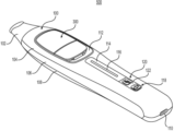
도 1은 예시적인 실시예에 따른 니코틴 e-베이핑 장치의 정면도이다.
도 2는 도 1의 니코틴 e-베이핑 장치의 측면도이다.
도 3은 도 1의 니코틴 e-베이핑 장치의 배면도이다.
도 4는 도 1의 니코틴 e-베이핑 장치의 근위 단부도이다.
도 5는 도 1의 니코틴 e-베이핑 장치의 원위 단부도이다.
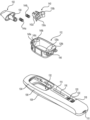
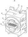
도 6은 도 1의 니코틴 e-베이핑 장치의 사시도이다.
도 7은 도 6의 포드 유입구의 확대도이다.
도 8은 도 6의 니코틴 e-베이핑 장치의 단면도이다.
도 9는 도 6의 니코틴 e-베이핑 장치의 장치 몸체의 사시도이다.
도 10은 도 9의 장치 몸체의 정면도이다.
도 11은 도 10의 관통 구멍의 확대 사시도이다.
도 12는 도 10의 장치 전기 접촉부의 확대 사시도이다.
도 13은 도 12의 마우스피스를 수반하는 부분 분해도이다.
도 14는 도 9의 베젤 구조를 수반하는 부분 분해도이다.
도 15는 도 14의 마우스피스, 스프링, 유지 구조, 및 베젤 구조의 확대 사시도이다.
도 16은 도 14의 전방 커버, 프레임, 및 후방 커버를 수반하는 부분 분해도이다.
도 17은 도 6의 니코틴 e-베이핑 장치의 니코틴 포드 조립체의 사시도이다.
도 18은 도 17의 니코틴 포드 조립체의 다른 사시도이다.
도 19는 도 18의 니코틴 포드 조립체의 다른 사시도이다.
도 20은 커넥터 모듈이 없는 도 19의 니코틴 포드 조립체의 다른 사시도이다.
도 21은 도 19의 커넥터 모듈의 사시도이다.
도 22는 도 21의 커넥터 모듈의 다른 사시도이다.
도 23은 도 22의 심지, 히터, 전기 리드 및 접촉 코어를 수반하는 분해도이다.
도 24는 도 17의 니코틴 포드 조립체의 제1 하우징 섹션을 수반하는 분해도이다.
도 25는 도 17의 니코틴 포드 조립체의 제2 하우징 섹션을 수반하는 부분 분해도이다.
도 26은 도 25의 활성 핀의 분해도이다.
도 27은 심지, 히터, 전기 리드 및 접촉 코어가 없는 도 22의 커넥터 모듈의 사시도이다.
도 28은 도 27의 커넥터 모듈의 분해도이다.
도 29는 예시적인 실시예에 따른 니코틴 e-베이핑 장치의 장치 몸체 및 니코틴 포드 조립체의 전기 시스템을 도시한다.
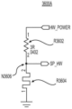
도 30은 예시적인 실시예에 따른 자동 셧다운 제어 시스템(2300)을 도시하는 단순 블록도이다.
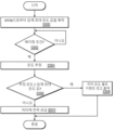
도 31은 예시적인 실시예에 따른 유휴 이벤트를 검출하기 위한 방법을 도시하는 흐름도이다.
도 32a는 예시적인 일 실시예에 따른 히터 온도 폴트 이벤트를 검출하기 위한 방법을 도시하는 흐름도이다.
도 32b는 다른 예시적인 실시예에 따른 히터 온도 폴트 이벤트를 검출하기 위한 방법을 도시하는 흐름도이다.
도 33a 및 도 33b는 하나 이상의 예시적인 실시예에 따른 자동 셧다운 제어 방법을 도시한다.
도 34는 히터 전압 측정 회로(21252)의 예시적인 일 실시예를 도시한다.
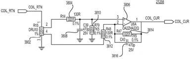
도 35는 도 29의 히터 전류 측정 회로(21258)의 예시적인 일 실시예를 도시한다.
도 36은 예시적인 일 실시예에 따른 포드 온도 측정 회로를 도시한다.
도 37은 다른 예시적인 실시예에 따른 포드 온도 측정 회로를 도시한다.
도 38은 예시적인 일 실시예에 따른 가열 엔진 제어 회로를 도시하는 회로도이다.
도 39는 예시적인 일 실시예에 따른 다른 가열 엔진 제어 회로를 도시하는 회로도이다.
도 40은 예시적인 일 실시예에 따른 온도 감지 변환기를 도시한다.
도 41은 다른 예시적인 실시예에 따른 온도 감지 변환기를 도시한다.
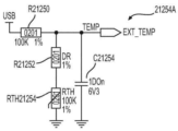
도 42a는 예시적인 일 실시예에 따른 전력 공급부 온도 측정 회로를 도시한다.
도 42b는 다른 예시적인 실시예에 따른 전력 공급부 온도 측정 회로를 도시한다.
도 43a는 예시적인 일 실시예에 따른 전력 공급부 전압 측정 회로를 도시한다.
도 43b는 예시적인 일 실시예에 따른 전력 공급부 전압 측정 회로를 도시한다.
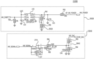
도 44a는 예시적인 일 실시예에 따른 충전기를 도시한다.
도 44b는 다른 예시적인 실시예에 따른 충전기를 도시한다.1 is a front view of a nicotine e-vaping device according to an exemplary embodiment.
Figure 2 is a side view of the nicotine e-vaping device of Figure 1;
Figure 3 is a rear view of the nicotine e-vaping device of Figure 1;
Figure 4 is a proximal end view of the nicotine e-vaping device of Figure 1;
5 is a distal end view of the nicotine e-vaping device of FIG. 1;
Figure 6 is a perspective view of the nicotine e-vaping device of Figure 1;
7 is an enlarged view of the pod inlet of FIG. 6;
Figure 8 is a cross-sectional view of the nicotine e-vaping device of Figure 6;
Figure 9 is a perspective view of the device body of the nicotine e-vaping device of Figure 6;
Fig. 10 is a front view of the device body of Fig. 9;
Fig. 11 is an enlarged perspective view of the through hole of Fig. 10;
Fig. 12 is an enlarged perspective view of the electrical contacts of the device of Fig. 10;
Fig. 13 is a partially exploded view of the mouthpiece of Fig. 12;
Figure 14 is a partial exploded view accompanying the bezel structure of Figure 9;
FIG. 15 is an enlarged perspective view of the mouthpiece, spring, retaining structure, and bezel structure of FIG. 14;
16 is a partially exploded view of the front cover, frame, and rear cover of FIG. 14;
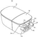
17 is a perspective view of the nicotine pod assembly of the nicotine e-vaping device of FIG. 6;
Figure 18 is another perspective view of the nicotine pod assembly of Figure 17;
Fig. 19 is another perspective view of the nicotine pod assembly of Fig. 18;
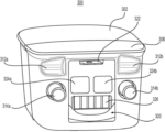
20 is another perspective view of the nicotine pod assembly of FIG. 19 without the connector module.
21 is a perspective view of the connector module of FIG. 19;
22 is another perspective view of the connector module of FIG. 21;
Figure 23 is an exploded view of the wick, heater, electrical lead and contact core of Figure 22;
24 is an exploded view accompanying the first housing section of the nicotine pod assembly of FIG. 17;
25 is a partial exploded view of the nicotine pod assembly of FIG. 17 accompanying the second housing section;
Fig. 26 is an exploded view of the active pin of Fig. 25;
Fig. 27 is a perspective view of the connector module of Fig. 22 without the wick, heater, electrical leads and contact core;
28 is an exploded view of the connector module of FIG. 27;
29 illustrates the electrical system of the nicotine pod assembly and device body of a nicotine e-vaping device according to an exemplary embodiment.
30 is a simplified block diagram illustrating an automatic shutdown control system 2300 according to an exemplary embodiment.
Fig. 31 is a flow chart illustrating a method for detecting an idle event according to an exemplary embodiment.
32A is a flow diagram illustrating a method for detecting a heater temperature fault event according to an exemplary embodiment.
32B is a flow diagram illustrating a method for detecting a heater temperature fault event according to another exemplary embodiment.
33A and 33B illustrate an automatic shutdown control method according to one or more illustrative embodiments.
34 shows one exemplary embodiment of a heater
FIG. 35 shows one exemplary embodiment of the heater
36 shows a pod temperature measurement circuit according to one exemplary embodiment.
37 shows a pod temperature measurement circuit according to another exemplary embodiment.
Fig. 38 is a circuit diagram showing a heating engine control circuit according to an exemplary embodiment.
Fig. 39 is a circuit diagram showing another heating engine control circuit according to an exemplary embodiment.
40 shows a temperature sensing transducer according to one exemplary embodiment.
41 shows a temperature sensing transducer according to another exemplary embodiment.
42A shows a power supply temperature measurement circuit according to an exemplary embodiment.
42B shows a power supply temperature measurement circuit according to another exemplary embodiment.
43A shows a power supply voltage measurement circuit according to an exemplary embodiment.
43B shows a power supply voltage measurement circuit according to an exemplary embodiment.
44A shows a charger according to an exemplary embodiment.
44B shows a charger according to another exemplary embodiment.
일부 상세한 예시적인 실시예가 본원에 개시된다. 그러나, 본원에 개시된 특정 구조적 그리고 기능적 세부 사항은 단지 예시적인 실시예를 설명하기 위한 대표적인 예일뿐이다. 그러나, 예시적인 실시예는 많은 대안적인 형태로 실시될 수 있으며, 본원에서 설명된 예시적인 실시예에만 한정되는 것으로 해석되어서는 안된다.Some detailed exemplary embodiments are disclosed herein. However, specific structural and functional details disclosed herein are merely representative examples for describing illustrative embodiments. The illustrative embodiments may, however, be embodied in many alternative forms and should not be construed as limited to the illustrative embodiments set forth herein.
따라서, 예시적인 실시예가 다양한 변형 및 대안적인 형태가 가능하지만, 그의 예시적인 실시예는 도면에 예로서 도시되며 본원에서 상세히 설명될 것이다. 그러나, 예시적인 실시예를 개시된 특정 형태로 한정하려는 의도는 없지만, 반대로, 예시적인 실시예는 개시된 특정 형태의 모든 변형, 등가물 및 대체물을 포함하는 것으로 이해되어야 한다. 동일한 도면 부호는 도면의 설명 전반에 걸쳐 동일한 요소를 지칭한다.Accordingly, while the illustrative embodiments are capable of various modifications and alternative forms, the illustrative embodiments thereof are illustrated by way of example in the drawings and will be described in detail herein. However, there is no intention to limit the illustrative embodiments to the specific forms disclosed, but on the contrary, it should be understood that the illustrative embodiments include all modifications, equivalents, and substitutions of the specific forms disclosed. Like reference numbers refer to like elements throughout the description of the drawings.
하나의 요소 또는 층이 다른 요소 또는 층의 "위에", "그에 연결된", "그에 결합된", "그에 부착된", "그에 인접한" 또는 이를 "커버하는" 것으로 언급될 때, 이는 다른 요소 또는 층 위에 직접 있거나, 연결되거나, 결합되거나, 부착되거나, 인접하거나 커버할 수 있거나 개재 요소 또는 층이 존재할 수 있다. 대조적으로, 하나의 요소가 다른 요소 또는 층에 "직접 위에", "직접 연결된" 또는 "직접 결합된" 것으로 언급될 때, 개재 요소 또는 층이 존재하지 않는다. 동일한 번호는 본 명세서 전반에 걸쳐 동일한 요소를 지칭한다. 본원에서 사용되는 바와 같이, 용어 "및/또는"은 하나 이상의 관련 열거된 항목들의 임의의 그리고 모든 조합 또는 하위 조합을 포함하고 있다.When one element or layer is referred to as being “on”, “connected to”, “coupled to”, “attached to”, “adjacent to” or “covering” another element or layer, this refers to the other element or layer. or directly on, connected to, bonded to, attached to, adjacent to or covering a layer or intervening elements or layers may be present. In contrast, when an element is referred to as being “directly on,” “directly connected to,” or “directly coupled to” another element or layer, there are no intervening elements or layers present. Like numbers refer to like elements throughout this specification. As used herein, the term “and/or” includes any and all combinations or subcombinations of one or more of the related listed items.
용어 제1, 제2, 제3 등이 본원에서 다양한 요소, 영역, 층 또는 섹션을 설명하는 데 사용될 수 있지만, 이들 요소, 영역, 층 및 섹션은 이들 용어에 의해 한정되어서는 안된다는 점을 이해해야 한다. 이들 용어는 하나의 요소, 영역, 층 또는 부분을 또 다른 영역, 층 또는 부분과 구별하기 위해서만 사용된다. 그러므로, 이하에 논의되는 제1 요소, 영역, 층 또는 섹션은 예시적인 실시예의 교시를 벗어나지 않고 제2 요소, 영역, 층 또는 섹션으로 지칭될 수 있다.Although the terms first, second, third, etc. may be used herein to describe various elements, regions, layers or sections, it should be understood that these elements, regions, layers and sections should not be limited by these terms. . These terms are only used to distinguish one element, region, layer or section from another region, layer or section. Thus, a first element, region, layer or section discussed below could be termed a second element, region, layer or section without departing from the teachings of the exemplary embodiments.
본원에서 공간적으로 상대적인 용어(예: "밑에", "아래", "하부", "위에", "상부" 등)는 도면에 도시된 하나의 요소 또는 특징의 다른 요소 또는 특징에 대한 관계를 기술함에 있어서 설명을 용이하게 하기 위해 사용될 수 있다. 공간적으로 상대적인 용어는 도면에 도시된 배향뿐만 아니라 사용 또는 작동 시 장치의 상이한 배향을 포함하도록 의도된 것임을 이해해야 한다. 예를 들어, 도면 내의 장치가 뒤집혀 있다면, 다른 요소 또는 특징의 "아래" 또는 "밑"으로 기재된 요소는 다른 요소 또는 특징의 "위"에 배향될 것이다. 따라서, 용어 "아래"는 위와 아래의 배향 둘 모두를 포괄할 수 있다. 장치는 달리 배향될 수 있고(90도 또는 다른 배향으로 회전될 수 있음), 본원에서 사용된 공간적으로 상대적인 기술어는 그에 따라 해석될 수 있다.Spatially relative terms herein (eg, "below", "below", "lower", "above", "upper", etc.) describe the relationship of one element or feature to another element or feature shown in a figure. may be used to facilitate explanation. It should be understood that spatially relative terms are intended to include different orientations of the device in use or operation, as well as the orientation shown in the figures. For example, if the device in the figures is inverted, elements described as “below” or “beneath” other elements or features will be oriented “above” the other elements or features. Thus, the term “below” can encompass both an orientation of above and below. The device may be otherwise oriented (rotated 90 degrees or at other orientations) and the spatially relative descriptors used herein interpreted accordingly.
본원에서 사용된 용어는 단지 다양한 예시적인 실시예를 설명하기 위한 것이며 예시적인 실시예를 한정하려는 것이 아니다. 본원에서 사용되는 바와 같이, 단수형 부정관사 "a", "an" 및 정관사 "the"는 문맥상 달리 표시하지 않는 한 복수 형태를 포함하는 것으로 의도된다. 용어 "포함하다(includes)", "포함하는(including)", "포함하다(comprises)" 및 "포함하는(comprising)"은 본 명세서에서 사용될 때, 규정된 특징, 정수, 단계, 작동, 및/또는 요소의 존재를 지정하지만, 하나 이상의 다른 특징, 정수, 단계, 작동, 요소, 및/또는 이들의 그룹의 존재 또는 추가를 배제하지 않는다는 점이 추가로 이해될 것이다.Terminology used herein is merely for describing various exemplary embodiments and is not intended to limit the exemplary embodiments. As used herein, the singular indefinite articles "a", "an" and the definite article "the" are intended to include the plural forms unless the context indicates otherwise. The terms "includes", "including", "comprises" and "comprising", when used herein, refer to defined features, integers, steps, operations, and It will be further understood that while specifying the presence of/or elements, it does not preclude the presence or addition of one or more other features, integers, steps, operations, elements, and/or groups thereof.
단어 "약" 및 "실질적으로"가 수치와 관련하여 본 명세서에 사용될 때, 연관된 수치는 달리 명시적으로 정의되지 않는 한, 대략 언급된 수치의 ±10%의 허용 오차를 포함하도록 의도된다. When the words "about" and "substantially" are used herein in reference to numerical values, the associated numerical values are intended to include a tolerance of approximately ±10% of the recited numerical value, unless expressly defined otherwise.
달리 정의되지 않는 한, 본원에 사용되는 모든 용어(기술 용어 및 과학 용어 포함)는 예시적인 실시예가 속하는 당해 기술분야의 숙련자가 보편적으로 이해하는 것과 동일한 의미를 갖는다. 공통적으로 사용되는 사전에서 정의된 것을 포함하는 용어는, 관련 분야의 맥락에서의 의미와 일치하는 의미를 갖는 것으로 해석되어야 하며 명시적으로 여기에서 정의되지 않는 한 이상적이거나 지나치게 형식적인 의미로 해석되지 않을 것이다.Unless defined otherwise, all terms (including technical and scientific terms) used herein have the same meaning as commonly understood by one of ordinary skill in the art to which the illustrative embodiments belong. Terms, including those defined in commonly used dictionaries, are to be interpreted as having a meaning consistent with that in the context of the relevant field and not in an idealized or overly formal sense unless explicitly defined herein. will be.
본원에서 사용되는 바와 같이, "니코틴 전자 베이핑 장치"는 니코틴 e-베이핑 장치"는 경우에 따라, 니코틴 전자 기화 장치, 및 니코틴 e-베이핑 장치를 사용하는 것으로 지칭될 수 있고, 이와 동의어로 간주될 수 있다.As used herein, "nicotine e-vaping device" means "nicotine e-vaping device" may refer to a nicotine e-vaporizing device, and a nicotine e-vaping device, as the case may be, and is synonymous therewith. can be regarded as
도 1은 예시적인 실시예에 따른 니코틴 e-베이핑 장치의 정면도이다. 도 2는 도 1의 니코틴 e-베이핑 장치의 측면도이다. 도 3은 도 1의 니코틴 e-베이핑 장치의 배면도이다. 도 1 내지 도 3을 참조하면, 니코틴 e-베이핑 장치(500)는 니코틴 포드 조립체(300)를 수용하도록 구성된 장치 몸체(100)를 포함한다. 니코틴 포드 조립체(300)는 니코틴 기화전 제제를 유지하도록 구성된 모듈형 물품이다. "니코틴 기화전 제제"는 증기로 변환될 수 있는 재료 또는 재료들의 조합이다. 예를 들어, 니코틴 기화전 제제는 물, 비드, 용매, 활성 성분, 에탄올, 식물 추출물, 천연 또는 인공 향미, 및/또는 글리세린 및 프로필렌 글리콜과 같은 증기 형성제를 포함하되, 이에 한정되지 않는, 액체, 고체, 및/또는 겔 제제일 수 있다. 베이핑 동안, 니코틴 e-베이핑 장치(500)는 증기를 발생시키기 위해 니코틴 기화전 제제를 가열하도록 구성된다. 본원에서 지칭되는 바와 같이, "니코틴 증기"는 본원에 개시된 예시적인 실시예 중 어느 하나에 따른 임의의 니코틴 e-베이핑 장치로부터 발생되거나 방출되는 임의의 재료이다.1 is a front view of a nicotine e-vaping device according to an exemplary embodiment. Figure 2 is a side view of the nicotine e-vaping device of Figure 1; Figure 3 is a rear view of the nicotine e-vaping device of Figure 1; Referring to FIGS. 1-3 , a
도 1 및 도 3에 도시된 바와 같이, 니코틴 e-베이핑 장치(500)는 길이방향으로 연장되고 그의 폭보다 더 큰 길이를 갖는다. 게다가, 도 2에 도시된 바와 같이, 니코틴 e-베이핑 장치(500)의 길이는 또한 그의 두께보다 더 크다. 더욱이, 니코틴 e-베이핑 장치(500)의 폭은 그의 두께보다 더 클 수 있다. x-y-z 직교 좌표계를 가정하면, 니코틴 e-베이핑 장치(500)의 길이는 y 방향으로 측정될 수 있고, 폭은 x 방향으로 측정될 수 있고, 두께는 z 방향으로 측정될 수 있다. 니코틴 e-베이핑 장치(500)는 그의 전방, 측면 및 후방 뷰에 기초하여 테이퍼형 단부를 갖는 실질적으로 선형인 형태를 가질 수 있지만, 예시적인 실시예는 이에 한정되지 않는다.As shown in Figures 1 and 3, the
장치 몸체(100)는 전방 커버(104), 프레임(106), 및 후방 커버(108)를 포함한다. 전방 커버(104), 프레임(106), 및 후방 커버(108)는 니코틴 e-베이핑 장치(500)의 작동과 연관된 기계적 요소, 전자 요소, 및/또는 회로를 둘러싸는 장치 하우징을 형성한다. 예를 들어, 장치 몸체(100)의 장치 하우징은 니코틴 e-베이핑 장치(500)에 전력을 공급하도록 구성된 전원을 둘러쌀 수 있으며, 이는 니코틴 포드 조립체(300)에 전류를 공급하는 것을 포함할 수 있다. 장치 몸체(100)의 장치 하우징은 또한 니코틴 e-베이핑 장치(500)를 제어하기 위한 하나 이상의 전기 시스템을 포함할 수 있다. 예시적인 실시예에 따른 전기 시스템은 나중에 더 상세히 논의될 것이다. 게다가, 조립될 때, 전방 커버(104), 프레임(106), 및 후방 커버(108)는 장치 몸체(100)의 가시적 부분의 대부분을 구성할 수 있다.
전방 커버(104)(예: 제1 커버)는 베젤 구조(112)를 수용하도록 구성된 일차 개구를 정의한다. 일차 개구는 둥근 직사각형 형상을 가질 수 있지만, 다른 형상이 베젤 구조(112)의 형상에 따라 가능하다. 베젤 구조(112)는 니코틴 포드 조립체(300)를 수용하도록 구성된 관통 구멍(150)을 정의한다. 관통 구멍(150)은 예를 들어, 도 9와 관련하여 보다 상세히 논의된다.Front cover 104 (eg, first cover) defines a primary opening configured to receive
전방 커버(104)는 또한 도광체 배열을 수용하도록 구성된 이차 개구를 정의한다. 이차 개구는 슬롯(예: 에지가 둥근 세장형 직사각형)과 유사할 수 있지만, 도광체 배열의 형상에 따라 다른 형상이 가능하다. 예시적인 실시예에서, 도광체 배열은 도광체 하우징(114) 및 버튼 하우징(122)을 포함한다. 도광체 하우징(114)은 도광체 렌즈(116)를 노출시키도록 구성되는 반면, 버튼 하우징(122)은 제1 버튼 렌즈(124) 및 제2 버튼 렌즈(126)을 노출시키도록 구성된다(예: 도 16). 제1 버튼 렌즈(124) 및 버튼 하우징(122)의 상류 부분은 제1 버튼(118)을 형성할 수 있다. 유사하게, 제2 버튼 렌즈(126) 및 버튼 하우징(122)의 하류 부분은 제2 버튼(120)을 형성할 수 있다. 버튼 하우징(122)은 단일 구조 또는 2개의 개별 구조의 형태일 수 있다. 후자의 형태로, 제1 버튼(118) 및 제2 버튼(120)은 누를 때 보다 독립적인 느낌으로 이동할 수 있다.The
니코틴 e-베이핑 장치(500)의 작동은 제1 버튼(118) 및 제2 버튼(120)에 의해 제어될 수 있다. 예를 들어, 제1 버튼(118)은 파워 버튼일 수 있고, 제2 버튼(120)은 강도 버튼일 수 있다. 2개의 버튼이 도광체 배열과 관련하여 도면에 도시되지만, 이용 가능한 특징 및 원하는 사용자 인터페이스에 따라 더 많은 (또는 더 적은) 버튼이 제공될 수 있다는 것을 이해해야 한다.Operation of the
프레임(106)(예: 베이스 프레임)은 장치 몸체(100)(및 니코틴 e-베이핑 장치(500) 전체)를 위한 중앙 지지 구조물이다. 프레임(106)은 섀시로 지칭될 수 있다. 프레임(106)은 근위 단부, 원위 단부, 및 근위 단부와 원위 단부 사이의 한 쌍의 측면 섹션을 포함한다. 근위 단부 및 원위 단부는 또한 하류 단부 및 상류 단부로 각각 지칭될 수 있다. 본원에서 사용되는 바와 같이, "근위"(및 역으로 "원위")는 베이핑 동안 성인 베이퍼와 관련이 있고, "하류"(및 역으로 "상류")는 니코틴 증기의 흐름과 관련이 있다. 가교 섹션은 추가적인 강도 및 안정성을 위해 측면 섹션의 대향하는 내부 표면들 사이에(예: 프레임(106)의 길이를 따라 중간 주위에) 제공될 수 있다. 프레임(106)은 모놀리식 구조가 되도록 일체형으로 형성될 수 있다.Frame 106 (eg, base frame) is the central support structure for device body 100 (and
구성 재료와 관련하여, 프레임(106)은 합금 또는 플라스틱으로 형성될 수 있다. 합금(예: 다이 캐스트 등급, 가공 가능한 등급)은 알루미늄(Al) 합금 또는 아연(Zn) 합금일 수 있다. 플라스틱은 폴리카보네이트(PC), 아크릴로니트릴 부타디엔 스티렌(ABS), 또는 이들의 조합(PC/ABS)일 수 있다. 예를 들어, 폴리카보네이트는 LUPOY SC1004A일 수 있다. 더욱이, 프레임(106)에는 기능적 및/또는 심미적 이유로(예: 고급 외관을 제공하기 위해) 표면 마감이 제공될 수 있다. 예시적인 실시예에서, 프레임(106)은 (예: 알루미늄 합금으로 형성될 때) 양극산화처리될 수 있다. 다른 실시예에서, 프레임(106)은 (예: 아연 합금으로 형성될 때) 경질 에나멜로 코팅되거나 도장될 수 있다. 다른 실시예에서, 프레임(106)은 (예: 폴리카보네이트로 형성될 때) 금속화될 수 있다. 또 다른 실시예에서, 프레임(106)은 (예: 아크릴로니트릴 부타디엔 스티렌으로 형성될 때) 전기도금될 수 있다. 프레임(106)에 관한 구성 재료는 또한 니코틴 e-베이핑 장치(500)의 전방 커버(104), 후방 커버(108), 및/또는 다른 적절한 부분에 적용 가능할 수 있다는 점을 이해해야 한다.Regarding the materials of construction, the
후방 커버(108)(예: 제2 커버)는 또한 베젤 구조(112)를 수용하도록 구성된 개구를 정의한다. 개구는 둥근 직사각형 형상을 가질 수 있지만, 다른 형상이 베젤 구조(112)의 형상에 따라 가능하다. 예시적인 실시예에서, 후방 커버(108) 내의 개구는 전방 커버(104) 내의 일차 개구보다 작다. 또한, 도시되지는 않았지만, (예: 버튼을 포함하는) 도광체 배열이 니코틴 e-베이핑 장치(500)의 전방 상의 도광체 배열에 더하여(또는 그 대신에) 니코틴 e-베이핑 장치(500)의 후방에 제공될 수 있음을 이해해야 한다.The rear cover 108 (eg, the second cover) also defines an opening configured to receive the
전방 커버(104) 및 후방 커버(108)는 스냅핏 배열을 통해 프레임(106)과 치합하도록 구성될 수 있다. 예를 들어, 전방 커버(104) 및/또는 후방 커버(108)는 프레임(106)의 대응하는 정합 부재와 맞물리도록 구성된 클립을 포함할 수 있다. 비제한적인 실시예에서, 클립은 프레임(106)의 대응하는 정합 부재(예: 베벨된 에지를 갖는 돌출부)를 수용하도록 구성된 오리피스를 갖는 탭의 형태일 수 있다. 대안적으로, 전방 커버(104) 및/또는 후방 커버(108)는 억지 끼워맞춤(또한 프레스 끼워맞춤 또는 마찰 끼워맞춤으로 지칭될 수 있음)을 통해 프레임(106)과 치합하도록 구성될 수 있다. 그러나, 전방 커버(104), 프레임(106), 및 후방 커버(108)는 다른 적합한 배열 및 기술을 통해 결합될 수 있다는 점을 이해해야 한다.
장치 몸체(100)는 또한 마우스피스(102)를 포함한다. 마우스피스(102)는 프레임(106)의 근위 단부에 고정될 수 있다. 추가적으로, 도 2에 도시된 바와 같이, 프레임(106)이 전방 커버(104)와 후방 커버(108) 사이에 끼워져 있는 예시적인 실시예에서, 마우스피스(102)는 전방 커버(104), 프레임(106), 및 후방 커버(108)와 접경할 수 있다. 더욱이, 비제한적인 실시예에서, 마우스피스(102)는 베이어닛 연결을 통해 장치 하우징과 결합될 수 있다.The
도 4는 도 1의 니코틴 e-베이핑 장치의 근위 단부도이다. 도 4를 참조하면, 마우스피스(102)의 배출구 면은 복수의 증기 배출구를 정의한다. 비제한적인 실시예에서, 마우스피스(102)의 배출구 면은 타원형 형상일 수 있다. 게다가, 마우스피스(102)의 배출구 면은 타원형 형상 배출구 면의 주축에 대응하는 제1 크로스바 및 타원형 형상 배출구 면의 단축에 대응하는 제2 크로스바를 포함할 수 있다. 더욱이, 제1 크로스바 및 제2 크로스바는 수직으로 교차하고, 마우스피스(102)의 일체로 형성된 부분일 수 있다. 배출구 면이 4개의 증기 배출구를 정의하는 것으로 도시되지만, 예시적인 실시예가 이에 한정되지 않음을 이해해야 한다. 예를 들어, 배출구 면은 4개 미만(예: 1개, 2개)의 증기 배출구 또는 4개 초과(예: 6개, 8개)의 증기 배출구를 정의할 수 있다.Figure 4 is a proximal end view of the nicotine e-vaping device of Figure 1; Referring to FIG. 4 , the outlet face of the
도 5는 도 1의 니코틴 e-베이핑 장치의 원위 단부도이다. 도 5를 참조하면, 니코틴 e-베이핑 장치(500)의 원위 말단은 포트(110)를 포함하고 있다. 포트(110)는 니코틴 e-베이핑 장치(500) 내의 내부 전원을 충전하기 위해 외부 전원으로부터 (예: USB 케이블을 통해) 전류를 수용하도록 구성되어 있다. 게다가, 포트(110)는 (예: USB 케이블을 통해) 다른 니코틴 e-베이핑 장치 또는 다른 전자 장치(예: 전화, 태블릿, 컴퓨터)에 데이터를 송신하고/하거나 이로부터 데이터를 수신하도록 구성될 수도 있다. 더욱이, 니코틴 e-베이핑 장치(500)는 그 전자 장치 상에 설치된 애플리케이션 소프트웨어(앱)를 통해 전화와 같은 다른 전자 장치와 무선 통신을 위해 구성될 수 있다. 이러한 경우에, 성인 베이퍼는 앱을 통해 니코틴 e-베이핑 장치(500)를 제어하거나 그렇지 않으면 이와 인터페이스할(예: 니코틴 e-베이핑 장치를 위치시키고, 사용 정보를 체크하고, 작동 파라미터를 변경할) 수 있다.5 is a distal end view of the nicotine e-vaping device of FIG. 1; Referring to FIG. 5 , the distal end of the
도 6은 도 1의 니코틴 e-베이핑 장치의 사시도이다. 도 7은 도 6의 포드 유입구의 확대도이다. 도 6 내지 도 7을 참조하고, 간략하게 위에 언급된 바와 같이, 니코틴 e-베이핑 장치(500)는 니코틴 기화전 제제를 유지하도록 구성된 니코틴 포드 조립체(300)를 포함한다. 니코틴 포드 조립체(300)는 (도광체 배열과 대면하는) 상류 단부 및 (마우스피스(102)와 대면하는) 하류 단부를 갖는다. 비제한적인 실시예에서, 상류 단부는 하류 단부로부터 니코틴 포드 조립체(300)의 대향 표면이다. 니코틴 포드 조립체(300)의 상류 단부는 포드 유입구(322)를 정의한다. 장치 몸체(100)는 니코틴 포드 조립체(300)를 수용하도록 구성된 관통 구멍(예: 도 9의 관통 구멍(150))을 정의한다. 예시적인 실시예에서, 장치 몸체(100)의 베젤 구조(112)는 관통 구멍을 정의하고 상류 림을 포함한다. 도시된 바와 같이, 특히 도 7에서, 베젤 구조(112)의 상류 림은 니코틴 포드 조립체(300)가 장치 몸체(100)의 관통 구멍 내에 안착될 때 포드 유입구(322)를 노출시키도록 각을 이룬다(예: 안쪽으로 침지한다).Figure 6 is a perspective view of the nicotine e-vaping device of Figure 1; 7 is an enlarged view of the pod inlet of FIG. 6; Referring to FIGS. 6-7 and briefly mentioned above, the
예를 들어, (니코틴 포드 조립체(300)의 전방 면과 비교적 동일 평면에 있고, 따라서 포드 유입구(322)를 숨기기 위해) 전방 커버(104)의 윤곽을 따르기 보다는, 베젤 구조(112)의 상류 림은 주변 공기를 포드 유입구(322) 내로 유도하도록 구성된 스쿠프의 형태이다. 이러한 각진/스쿠프 구성은 니코틴 e-베이핑 장치(500)의 공기 유입구(예: 포드 유입구(322))의 차단을 감소시키거나 방지하는 것을 도울 수 있다. 스쿠프의 깊이는 니코틴 포드 조립체(300)의 상류 단부 면의 절반 미만(예: 1/4 미만)이 노출되도록 할 수 있다. 추가적으로, 비제한적인 실시예에서, 포드 유입구(322)는 슬롯의 형태이다. 더욱이, 장치 몸체(100)가 제1 방향으로 연장되는 것으로 간주되면, 이때 슬롯은 제2 방향으로 연장되는 것으로 간주될 수 있으며, 제2 방향은 제1 방향을 가로지른다.For example, rather than following the contours of the front cover 104 (to be relatively coplanar with the front face of the
도 8은 도 6의 니코틴 e-베이핑 장치의 단면도이다. 도 8에서, 단면은 니코틴 e-베이핑 장치(500)의 길이방향 축을 따라 취해진다. 도시된 바와 같이, 장치 몸체(100) 및 니코틴 포드 조립체(300)는 니코틴 e-베이핑 장치(500)의 작동과 연관된 기계적 요소, 전자 요소, 및/또는 회로를 포함하며, 이는 본원에서 보다 상세히 논의되고/되거나 본원에 참조로 통합된다. 예를 들어, 니코틴 포드 조립체(300)는 내부의 밀봉된 니코틴 저장소로부터 니코틴 기화전 제제를 방출하기 위해 작동되도록 구성된 기계적 요소를 포함할 수 있다. 니코틴 포드 조립체(300)는 또한 니코틴 포드 조립체(300)의 삽입 및 안착을 용이하게 하기 위해 장치 몸체(100)와 치합하도록 구성된 기계적 양태를 가질 수 있다.Figure 8 is a cross-sectional view of the nicotine e-vaping device of Figure 6; In FIG. 8 , a cross section is taken along the longitudinal axis of the
추가적으로, 니코틴 포드 조립체(300)는 장치 몸체(100)에/로부터 정보를 저장, 수신, 및/또는 송신하도록 구성된 전자 요소 및/또는 회로를 포함하는 "스마트 포드"일 수 있다. 이러한 정보는 장치 몸체(100)와 함께 사용하기 위한 니코틴 포드 조립체(300)를 인증하는 데(예: 미승인/허위 니코틴 포드 조립체의 사용을 방지하는 데) 사용될 수 있다. 더욱이, 정보는 이때, 식별된 유형에 기초하여 베이핑 프로필과 상관되는 니코틴 포드 조립체(300)의 유형을 식별하는데 사용될 수 있다. 베이핑 프로필은 니코틴 기화전 제제의 가열을 위한 일반 파라미터를 제시하도록 설계될 수 있고, 베이핑 전 및/또는 동안 성인 베이퍼에 의한 튜닝, 정제, 또는 다른 조정을 겪을 수 있다.Additionally,
니코틴 포드 조립체(300)는 또한 니코틴 e-베이핑 장치(500)의 작동과 관련될 수 있는 다른 정보를 장치 몸체(100)와 통신할 수 있다. 관련 정보의 예는 니코틴 포드 조립체(300) 내의 니코틴 기화전 제제의 수준 및/또는 니코틴 포드 조립체(300)가 장치 몸체(100) 내에 삽입되고 활성화된 후 경과한 시간의 길이를 포함할 수 있다. 예를 들어, 니코틴 포드 조립체(300)가 장치 몸체(100) 내에 삽입되고 소정의 시간 이전 기간(예: 6개월 전 초과)보다 더 많이 활성화되면, 니코틴 e-베이핑 장치(500)는 베이핑을 허용하지 않을 수 있고, 성인 베이퍼는 니코틴 포드 조립체(300)가 여전히 적절한 수준의 니코틴 기화전 제제를 함유하고 있음에도 불구하고 새로운 니코틴 포드 조립체로 변경하도록 재촉받을 수 있다.The
장치 몸체(100)는 니코틴 포드 조립체(300)를 치합, 유지, 및/또는 활성화하도록 구성된 기계적 요소(예: 상보적 구조)를 포함할 수 있다. 게다가, 장치 몸체(100)는 베이핑 동안 니코틴 포드 조립체(300)에 전력을 공급하도록 차례로 구성된 내부 전원(예: 배터리)을 충전하기 위해 전류를 수신하도록 구성된 전자 요소 및/또는 회로를 포함할 수 있다. 더욱이, 장치 몸체(100)는 니코틴 포드 조립체(300), 상이한 니코틴 e-베이핑 장치, 다른 전자 장치(예: 전화, 태블릿, 컴퓨터), 및/또는 성인 베이퍼와 통신하도록 구성된 전자 요소 및/또는 회로를 포함할 수 있다. 통신되는 정보는 포드 특정 데이터, 현재 베이핑 세부 사항, 및/또는 과거 베이핑 패턴/이력을 포함할 수 있다. 성인 베이퍼는 촉각(예: 진동), 청각(예: 비프음), 및/또는 시각(예: 컬러/점멸등)인 피드백과의 이러한 통신을 통지받을 수 있다. 정보의 충전 및/또는 통신은 포트(110)로(예: USB 케이블을 통해) 수행될 수 있다.
도 9는 도 6의 니코틴 e-베이핑 장치의 장치 몸체의 사시도이다. 도 9를 참조하면, 장치 몸체(100)의 베젤 구조(112)는 관통 구멍(150)을 정의한다. 관통 구멍(150)은 니코틴 포드 조립체(300)를 수용하도록 구성된다. 관통 구멍(150) 내에 니코틴 포드 조립체(300)의 삽입 및 안착을 용이하게 하기 위해, 베젤 구조(112)의 상류 림은 제1 상류 돌출부(128a) 및 제2 상류 돌출부(128b)를 포함한다. 관통 구멍(150)은 둥근 모서리를 갖는 직사각형 형상을 가질 수 있다. 예시적인 실시예에서, 제1 상류 돌출부(128a) 및 제2 상류 돌출부(128b)는 베젤 구조(112)와 일체로 형성되고 상류 림의 2개의 둥근 모서리에 위치한다.Figure 9 is a perspective view of the device body of the nicotine e-vaping device of Figure 6; Referring to FIG. 9 , the
베젤 구조(112)의 하류 측벽은 제1 하류 개구, 제2 하류 개구, 및 제3 하류 개구를 정의할 수 있다. 제1 하류 돌출부(130a) 및 제2 하류 돌출부(130b)를 포함하는 유지 구조는 제1 하류 돌출부(130a) 및 제2 하류 돌출부(130b)가 베젤 구조(112)의 제1 하류 개구 및 제2 하류 개구 각각을 통해 관통 구멍(150) 내로 돌출되도록 베젤 구조(112)와 치합된다. 게다가, 마우스피스(102)의 원위 단부는 제1 하류 돌출부(130a)와 제2 하류 돌출부(130b) 사이에 있도록 베젤 구조(112)의 제3 하류 개구를 통해 관통 구멍(150) 내로 연장된다.A downstream sidewall of the
도 10은 도 9의 장치 몸체의 정면도이다. 도 10을 참조하면, 장치 몸체(100)는 관통 구멍(150)의 상류 측에 배치된 장치 전기 커넥터(132)를 포함한다. 장치 몸체(100)의 장치 전기 커넥터(132)는 관통 구멍(150) 내에 안착되는 니코틴 포드 조립체(300)와 전기적으로 치합하도록 구성된다. 결과적으로, 전력은 베이핑 동안 장치 전기 커넥터(132)를 통해 장치 몸체(100)로부터 니코틴 포드 조립체(300)로 공급될 수 있다. 게다가, 데이터는 장치 전기 커넥터(132)를 통해 장치 몸체(100) 및 니코틴 포드 조립체(300)로 송신되고/되거나 그로부터 수신될 수 있다.Fig. 10 is a front view of the device body of Fig. 9; Referring to FIG. 10 , the
도 11은 도 10의 관통 구멍의 확대 사시도이다. 도 11을 참조하면, 마우스피스(102)의 제1 상류 돌출부(128a), 제2 상류 돌출부(128b), 제1 하류 돌출부(130a), 제2 하류 돌출부(130b), 및 원위 단부는 관통 구멍(150) 내로 돌출된다. 예시적인 실시예에서, 제1 상류 돌출부(128a) 및 제2 상류 돌출부(128b)는 고정 구조(예: 고정 피봇)인 반면, 제1 하류 돌출부(130a) 및 제2 하류 돌출부(130b)는 다루기 쉬운 구조(예: 수축 가능 부재)이다. 예를 들어, 제1 하류 돌출부(130a) 및 제2 하류 돌출부(130b)는 연장된 상태로 디폴트되도록(예: 스프링 로딩되도록) 구성될 수 있고 또한 니코틴 포드 조립체(300)의 삽입을 용이하게 하기 위해 수축된 상태로 일시적으로 전이되도록(그리고 연장된 상태로 가역적으로 되돌아가도록) 구성될 수 있다.Fig. 11 is an enlarged perspective view of the through hole of Fig. 10; Referring to FIG. 11 , the first
특히, 니코틴 포드 조립체(300)를 장치 몸체(100)의 관통 구멍(150) 내로 삽입할 때, 니코틴 포드 조립체(300)의 상류 단부 면에서의 오목부는 니코틴 포드 조립체(300)의 하류 단부 면에서의 오목부가 제1 하류 돌출부(130a) 및 제2 하류 돌출부(130b)와 치합될 때까지 제1 상류 돌출부(128a) 및 제2 상류 돌출부(128b)와 초기에 치합될 수 있고, 이어서 니코틴 포드 조립체(300)의 피봇팅이 (제1 상류 돌출부(128a) 및 제2 상류 돌출부(128b) 주위에) 이어질 수 있다. 이러한 경우에, 니코틴 포드 조립체(300)의 회전축은 (피봇팅 동안) 장치 몸체(100)의 길이방향 축에 직교할 수 있다. 게다가, 다루기 쉽도록 편향될 수 있는 제1 하류 돌출부(130a) 및 제2 하류 돌출부(130b)는 니코틴 포드 조립체(300)가 관통 구멍(150) 내로 피봇되고 니코틴 포드 조립체(300)의 하류 단부 면에서 오목부와 치합하도록 탄성적으로 연장될 때 수축될 수 있다. 더욱이, 니코틴 포드 조립체(300)의 하류 단부 면에서의 오목부와 제1 하류 돌출부(130a) 및 제2 하류 돌출부(130b)의 치합은 니코틴 포드 조립체(300)가 장치 몸체(100)의 관통 구멍(150) 내에 적절히 안착된다는 것을 성인 베이퍼에게 통지하기 위해 햅틱 및/또는 청각 피드백(예: 가청 클릭릭)을 생성할 수 있다.In particular, when inserting the
도 12는 도 10의 장치 전기 접촉부의 확대 사시도이다. 장치 몸체(100)의 장치 전기 접촉부는 니코틴 포드 조립체(300)가 장치 몸체(100)의 관통 구멍(150) 내에 안착될 때 니코틴 포드 조립체(300)의 포드 전기 접촉부와 치합하도록 구성된다. 도 12를 참조하면, 장치 몸체(100)의 장치 전기 접촉부는 장치 전기 커넥터(132)를 포함한다. 장치 전기 커넥터(132)는 전력 접촉부 및 데이터 접촉부를 포함한다. 장치 전기 커넥터(132)의 전력 접촉부는 장치 몸체(100)로부터 니코틴 포드 조립체(300)로 전력을 공급하도록 구성된다. 도시된 바와 같이, 장치 전기 커넥터(132)의 전력 접촉부는 제1 쌍의 전력 접촉부 및 제2 쌍의 전력 접촉부(후방 커버(108)보다 전방 커버(104)에 더 가깝게 위치됨)를 포함하고 있다. 제1 쌍의 전력 접촉부(예: 제1 상류 돌출부(128a)에 인접한 쌍)는 제2 쌍의 전력 접촉부와 별개이고 조립될 때 관통 구멍(150) 내로 연장되는 2개의 돌출부를 포함하는 단일 일체형 구조일 수 있다. 유사하게, 제2 쌍의 전력 접촉부(예: 제2 상류 돌출부(128b)에 인접한 쌍)은 제1 쌍의 전력 접촉부와 별개이고 조립될 때 관통 구멍(150) 내로 연장되는 2개의 돌출부를 포함하는 단일 일체형 구조일 수 있다. 장치 전기 커넥터(132)의 제1 쌍의 전력 접촉부 및 제2 쌍의 전력 접촉부는 디폴트로서 관통 구멍(150) 내로 돌출되고 편향을 극복하는 힘을 받을 때 관통 구멍(150)으로부터 (예: 독립적으로) 수축되도록 다루기 쉽게 장착되고 편향될 수 있다.Fig. 12 is an enlarged perspective view of the electrical contacts of the device of Fig. 10; The device electrical contacts of the
장치 전기 커넥터(132)의 데이터 접촉부는 니코틴 포드 조립체(300)와 장치 몸체(100) 사이에서 데이터를 송신하도록 구성된다. 도시된 바와 같이, 장치 전기 커넥터(132)의 데이터 접촉부는 (전방 커버(104)보다 후방 커버(108)에 더 가깝게 위치되는) 5개의 돌출부의 열을 포함한다. 장치 전기 커넥터(132)의 데이터 접촉부는 조립될 때 관통 구멍(150) 내로 연장되는 별개의 구조일 수 있다. 장치 전기 커넥터(132)의 데이터 접촉부는 또한 디폴트로서 관통 구멍(150) 내로 연장되고 편향을 극복하는 힘을 받을 때 관통 구멍(150)으로부터 (예: 독립적으로) 수축하도록 (예: 스프링으로) 다루기 쉽게 장착되고 편향될 수 있다. 예를 들어, 니코틴 포드 조립체(300)가 장치 몸체(100)의 관통 구멍(150) 내로 삽입될 때, 니코틴 포드 조립체(300)의 포드 전기 접촉부는 장치 몸체(100)의 대응하는 장치 전기 접촉부에 대해 가압될 것이다. 결과적으로, 장치 전기 커넥터(132)의 전력 접촉부 및 데이터 접촉부는 장치 몸체(100) 내로 수축(예: 적어도 부분적으로 수축)될 것이지만, 탄성 배열로 인해 대응하는 포드 전기 접촉부에 대해 계속 푸시되며, 이에 따라 장치 몸체(100)와 니코틴 포드 조립체(300) 사이의 적절한 전기적 연결을 보장하는 것을 도울 것이다. 더욱이, 이러한 연결은 또한 장치 몸체(100)와 니코틴 포드 조립체(300) 사이의 전력 및/또는 신호가 신뢰성 있고 정확하게 전송 및/또는 통신될 수 있도록 기계적으로 고정되고 최소 접촉 저항을 가질 수 있다. 다양한 양태가 장치 몸체(100)의 장치 전기 접촉부와 관련하여 논의되었지만, 예시적인 실시예가 이에 한정되지 않고 다른 구성이 이용될 수 있다는 점을 이해해야 한다.The data contacts of the device
도 13은 도 12의 마우스피스를 수반하는 부분 분해도이다. 도 13을 참조하면, 마우스피스(102)는 유지 구조(140)를 통해 장치 하우징과 치합하도록 구성된다. 예시적인 실시예에서, 유지 구조(140)는 주로 프레임(106)과 베젤 구조(112) 사이에 있도록 위치한다. 도시된 바와 같이, 유지 구조(140)는 유지 구조(140)의 근위 단부가 프레임(106)의 근위 단부를 통해 연장되도록 장치 하우징 내에 배치된다. 유지 구조(140)는 프레임(106)의 근위 단부를 약간 넘어서 연장되거나 그것과 함께 실질적으로 평탄할 수 있다. 유지 구조(140)의 근위 단부는 마우스피스(102)의 원위 단부를 수용하도록 구성된다. 유지 구조(140)의 근위 단부는 암형 단부일 수 있는 반면, 마우스피스의 원위 단부는 수형 단부일 수 있다.Fig. 13 is a partially exploded view of the mouthpiece of Fig. 12; Referring to FIG. 13 , the
예를 들어, 마우스피스(102)는 베이어닛 연결로 유지 구조(140)에 결합될(예: 가역적으로 결합될)수 있다. 이러한 경우에, 유지 구조(140)의 암형 단부는 한 쌍의 대향하는 L-형상 슬롯을 한정할 수 있는 반면, 마우스피스(102)의 수형 단부는 유지 구조(140)의 L-형상 슬롯과 치합하도록 구성된 대향하는 반경방향 부재(134)(예: 반경방향 핀)를 가질 수 있다. 유지 구조(140)의 L-형상 슬롯 각각은 길이방향 부분 및 원주 부분을 갖는다. 선택적으로, 원주 부분의 말단은 마우스피스(102)의 반경방향 부재(134)가 의도하지 않게 분리될 가능성을 감소시키거나 방지하는 것을 돕기 위해 세리프 부분을 가질 수 있다. 비제한적인 실시예에서, L-형상 슬롯의 길이방향 부분은 장치 몸체(100)의 길이방향 축을 따라 평행하게 연장되는 반면, L-형상 슬롯의 원주 부분은 장치 몸체(100)의 길이방향 축(예: 중심 축) 주위로 연장된다. 결과적으로, 마우스피스(102)를 장치 하우징에 결합하기 위해, 도 13에 도시된 마우스피스(102)는 반경방향 부재(134)를 유지 구조(140)의 L-형상 슬롯의 길이방향 부분에 대한 입구와 정렬하기 위해 초기에 90도 회전된다. 그 다음, 마우스피스(102)는 각각의 원주 부분과의 접합부에 도달할 때까지 반경방향 부재(134)가 L-형상 슬롯의 길이방향 부분을 따라 슬라이딩하도록 유지 구조(140) 내로 푸시된다. 그 다음, 이 점에서, 마우스피스(102)는 각각의 말단이 도달될 때까지 반경방향 부재(134)가 원주 부분을 가로질러 이동하도록 회전된다. 세리프 부분이 각각의 말단에 존재하는 경우, 햅틱 및/또는 청각 피드백(예: 가청 클릭)이 생성되어 마우스피스(102)가 장치 하우징에 적절히 결합되었음을 성인 베이퍼에게 통지할 수 있다.For example,
마우스피스(102)는 베이핑 동안 니코틴 증기가 흐르는 증기 통로(136)를 정의한다. 증기 통로(136)는 (니코틴 포드 조립체(300)가 장치 몸체(100) 내에 안착되는) 관통 구멍(150)과 유체 연통한다. 증기 통로(136)의 근위 단부는 플레어형 부분을 포함할 수 있다. 게다가, 마우스피스(102)는 단부 커버(138)를 포함할 수 있다. 단부 커버(138)는 그의 원위 단부에서 그의 근위 단부까지 테이퍼질 수 있다. 단부 커버(138)의 배출구 면은 복수의 증기 배출구를 정의한다. 4개의 증기 배출구가 단부 커버(138)에 도시되지만, 예시적인 실시예가 이에 한정되지 않음을 이해해야 한다.
도 14는 도 9의 베젤 구조를 수반하는 부분 분해도이다. 도 15는 도 14의 마우스피스, 스프링, 유지 구조, 및 베젤 구조의 확대 사시도이다. 도 14 및 도 15를 참조하면, 베젤 구조(112)는 상류 측벽 및 하류 측벽을 포함한다. 베젤 구조(112)의 상류 측벽은 커넥터 개구(146)를 정의한다. 커넥터 개구(146)는 장치 몸체(100)의 장치 전기 커넥터(132)를 노출시키거나 수용하도록 구성된다. 베젤 구조(112)의 하류 측벽은 제1 하류 개구(148a), 제2 하류 개구(148b), 및 제3 하류 개구(148c)를 정의한다. 베젤 구조(112)의 제1 하류 개구(148a) 및 제2 하류 개구(148b)는 유지 구조(140)의 제1 하류 돌출부(130a) 및 제2 하류 돌출부(130b)를 각각 수용하도록 구성된다. 베젤 구조(112)의 제3 하류 개구(148c)는 마우스피스(102)의 원위 단부를 수용하도록 구성된다.Figure 14 is a partial exploded view accompanying the bezel structure of Figure 9; FIG. 15 is an enlarged perspective view of the mouthpiece, spring, retaining structure, and bezel structure of FIG. 14; Referring to FIGS. 14 and 15 , the
도 14에 도시된 바와 같이, 제1 하류 돌출부(130a) 및 제2 하류 돌출부(130b)는 유지 구조(140)의 오목한 측면 상에 있다. 도 15에 도시된 바와 같이, 제1 포스트(142a) 및 제2 포스트(142b)는 유지 구조(140)의 대향하는 볼록한 측면 상에 있다. 제1 스프링(144a) 및 제2 스프링(144b)은 제1 포스트(142a) 및 제2 포스트(142b) 상에 각각 배치된다. 제1 스프링(144a) 및 제2 스프링(144b)은 베젤 구조(112)에 대해 유지 구조(140)를 편향시키도록 구성된다.As shown in FIG. 14 , the first
조립될 때, 베젤 구조(112)는 커넥터 개구(146)에 인접한 한 쌍의 탭을 통해 프레임(106)에 고정될 수 있다. 게다가, 유지 구조(140)는 제1 하류 돌출부(130a) 및 제2 하류 돌출부(130b)가 제1 하류 개구(148a) 및 제2 하류 개구(148b)를 통해 각각 연장되도록 베젤 구조(112)와 접경할 것이다. 마우스피스(102)는 마우스피스(102)의 원위 단부가 베젤 구조(112)의 제3 하류 개구(148c)뿐만 아니라 유지 구조(140)를 통해 연장되도록 유지 구조(140)에 결합될 것이다. 제1 스프링(144a) 및 제2 스프링(144b)은 프레임(106)과 유지 구조(140) 사이에 있을 것이다.When assembled,
니코틴 포드 조립체(300)가 장치 몸체(100)의 관통 구멍(150) 내로 삽입될 때, 니코틴 포드 조립체(300)의 하류 단부는 유지 구조(140)의 제1 하류 돌출부(130a) 및 제2 하류 돌출부(130b)에 대해 푸시될 것이다. 결과적으로, 유지 구조(140)의 제1 하류 돌출부(130a) 및 제2 하류 돌출부(130b)는 (제1 스프링(144a) 및 제2 스프링(144b)의 압축에 의해) 장치 몸체(100)의 관통 구멍(150)을 탄성적으로 산출하고 수축하며, 이에 따라 니코틴 포드 조립체(300)의 삽입이 진행될 수 있게 한다. 예시적인 실시예에서, 제1 하류 돌출부(130a) 및 제2 하류 돌출부(130b)가 장치 몸체(100)의 관통 구멍(150)으로부터 완전히 수축될 때, 유지 구조(140)의 변위는 제1 포스트(142a) 및 제2 포스트(142b)의 단부가 프레임(106)의 내부 단부 표면과 접촉하게 할 수 있다. 더욱이, 마우스피스(102)가 유지 구조(140)에 결합되기 때문에, 마우스피스(102)의 원위 단부는 관통 구멍(150)으로부터 수축될 것이고, 따라서 마우스피스(102)의 근위 단부(예: 단부 커버(138)를 포함하는 가시적 부분)이 또한 장치 하우징으로부터 멀리 대응하는 거리만큼 이동하게 된다.When the
니코틴 포드 조립체(300)가 적절히 삽입되어 니코틴 포드 조립체(300)의 제1 하류 오목부 및 제2 하류 오목부가 제1 하류 돌출부(130a) 및 제2 하류 돌출부(130b)와의 치합을 각각 허용하는 위치에 도달하면, 제1 스프링(144a) 및 제2 스프링(144b)의 압축으로부터의 저장된 에너지는 제1 하류 돌출부(130a) 및 제2 하류 돌출부(130b)가 니코틴 포드 조립체(300)의 제1 하류 오목부 및 상기 제2 하류 오목부와 탄성적으로 연장되고 치합하게 할 것이다. 더욱이, 상기 치합은 니코틴 포드 조립체(300)가 장치 몸체(100)의 관통 구멍(150) 내에 적절히 안착되었음을 성인 베이퍼에게 통지하기 위해 햅틱 및/또는 청각 피드백(예: 가청 클릭)을 생성할 수 있다.A position where the
도 16은 도 14의 전방 커버, 프레임, 및 후방 커버를 수반하는 부분 분해도이다. 도 16을 참조하면, 니코틴 e-베이핑 장치(500)의 작동과 연관된 다양한 기계적 요소, 전자 요소, 및/또는 회로가 프레임(106)에 고정될 수 있다. 전방 커버(104) 및 후방 커버(108)는 스냅핏 배열을 통해 프레임(106)과 치합하도록 구성될 수 있다. 예시적인 실시예에서, 전방 커버(104) 및 후방 커버(108)는 프레임(106)의 대응하는 정합 부재와 맞물리도록 구성된 클립을 포함한다. 클립은 프레임(106)의 대응하는 정합 부재(예: 베벨된 에지를 갖는 돌출부)를 수용하도록 구성된 오리피스를 갖는 탭의 형태일 수 있다. 도 16에서, 전방 커버(104)는 각각 4개의 클립(전방 커버(104)에 대한 총 8개의 클립)을 갖는 2개의 열을 갖는다. 유사하게, 후방 커버(108)는 (후방 커버(108)에 대한 총 8개의 클립에 대해) 각각 4개의 클립을 갖는 2개의 열을 갖는다. 프레임(106)의 대응하는 정합 부재는 프레임(106)의 내부 측벽 상에 있을 수 있다. 결과적으로, 치합된 클립 및 정합 부재는 전방 커버(104) 및 후방 커버(108)가 함께 스냅될 때 시야로부터 은폐될 수 있다. 대안적으로, 전방 커버(104) 및/또는 후방 커버(108)는 억지 끼워맞춤을 통해 프레임(106)과 치합하도록 구성될 수 있다. 그러나, 전방 커버(104), 프레임(106), 및 후방 커버(108)는 다른 적합한 배열 및 기술을 통해 결합될 수 있다는 점을 이해해야 한다.16 is a partially exploded view of the front cover, frame, and rear cover of FIG. 14; Referring to FIG. 16 , various mechanical, electronic, and/or circuitry associated with operation of nicotine
도 17은 도 6의 니코틴 e-베이핑 장치의 니코틴 포드 조립체의 사시도이다. 도 18은 도 17의 니코틴 포드 조립체의 다른 사시도이다. 도 19는 도 18의 니코틴 포드 조립체의 다른 사시도이다. 도 17 내지 도 19를 참조하면, 니코틴 e-베이핑 장치(500)용 니코틴 포드 조립체(300)는 니코틴 기화전 제제를 유지하도록 구성된 포드 몸체를 포함한다. 포드 몸체는 상류 단부 및 하류 단부를 갖는다. 포드 몸체의 상류 단부는 공동(310)을 정의한다(도 20). 포드 몸체의 하류 단부는 상류 단부에서 공동(310)과 유체 연통하는 포드 배출구(304)를 정의한다. 커넥터 모듈(320)은 포드 몸체의 공동(310) 내에 안착되도록 구성된다. 커넥터 모듈(320)은 외면 및 측면을 포함한다. 커넥터 모듈(320)의 외면은 포드 몸체의 외부를 형성한다.17 is a perspective view of the nicotine pod assembly of the nicotine e-vaping device of FIG. 6; Figure 18 is another perspective view of the nicotine pod assembly of Figure 17; Fig. 19 is another perspective view of the nicotine pod assembly of Fig. 18; 17-19, a
커넥터 모듈(320)의 외면은 포드 유입구(322)를 정의한다. (베이핑 동안 공기가 들어가는) 포드 유입구(322)는 (베이핑 동안 니코틴 증기가 빠져나오는) 포드 배출구(304)와 유체 연통한다. 포드 유입구(322)는 슬롯의 형태인 것으로 도 19에 도시된다. 그러나, 예시적인 실시예는 이에 한정되지 않고 다른 형태가 가능하다는 점을 이해해야 한다. 커넥터 모듈(320)이 포드 몸체의 공동(310) 내에 안착될 때, 커넥터 모듈(320)의 외면은 보이는 상태로 남아 있는 반면, 커넥터 모듈(320)의 측면은 주어진 각도에 기초하여 포드 유입구(322)를 통해 단지 부분적으로 볼 수 있도록 대부분 가려진다.The outer surface of the
커넥터 모듈(320)의 외면은 적어도 하나의 전기 접촉부를 포함하고 있다. 적어도 하나의 전기 접촉부는 복수의 전력 접촉부를 포함할 수 있다. 예를 들어, 복수의 전력 접촉부는 제1 전력 접촉부(324a) 및 제2 전력 접촉부(324b)를 포함할 수 있다. 니코틴 포드 조립체(300)의 제1 전력 접촉부(324a)는 장치 몸체(100)의 장치 전기 커넥터(132)의 제1 전력 접촉부 쌍(예: 도 12의 제1 상류 돌출부(128a)에 인접한 쌍)과 전기적으로 연결되도록 구성된다. 유사하게, 니코틴 포드 조립체(300)의 제2 전력 접촉부(324b)는 장치 몸체(100)의 장치 전기 커넥터(132)의 제2 전력 접촉부 쌍(예: 도 12의 제2 상류 돌출부(128b)에 인접한 쌍)와 전기적으로 연결되도록 구성된다. 게다가, 니코틴 포드 조립체(300)의 적어도 하나의 전기 접촉부는 복수의 데이터 접촉부(326)을 포함한다. 니코틴 포드 조립체(300)의 복수의 데이터 접촉부(326)는 장치 전기 커넥터(132)의 데이터 접촉부(예: 도 12의 5개의 돌출부의 열)과 전기적으로 연결되도록 구성된다. 2개의 전력 접촉부 및 5개의 데이터 접촉부가 니코틴 포드 조립체(300)와 관련하여 도시되지만, 다른 변형이 장치 몸체(100)의 설계에 따라 가능하다는 점을 이해해야 한다.The outer surface of the
예시적인 실시예에서, 니코틴 포드 조립체(300)는 전방 면, 전방 면에 대향하는 후방 면, 전방 면과 후방 면 사이의 제1 측면, 제1 측면에 대향하는 제2 측면면, 상류 단부 면, 및 상류 단부 면에 대향하는 하류 단부 면을 포함한다. 측면 및 단부 면의 모서리(예: 제1 측면 및 상류 단부 면의 모서리, 상류 단부 면 및 제2 측면의 모서리, 제2 측면 및 하류 단부 면의 모서리, 하류 단부 면 및 제1 측면의 모서리)는 원형일 수 있다. 그러나, 일부 경우에, 모서리는 각을 이룰 수 있다. 게다가, 전방 면의 주변 에지는 레지의 형태일 수 있다. 커넥터 모듈(320)의 외면은 니코틴 포드 조립체(300)의 상류 단부 면의 일부인 것으로 간주될 수 있다. 니코틴 포드 조립체(300)의 전방 면은 후방 면보다 더 넓고 더 길 수 있다. 이러한 경우에, 제1 측면 및 제2 측면은 서로를 향해 내측으로 각을 이룰 수 있다. 상류 단부 면 및 하류 단부 면은 또한 서로를 향해 내측으로 각을 이룰 수 있다. 각진 면 때문에, 니코틴 포드 조립체(300)의 삽입은 (예: 장치 몸체(100)의 전방 측면(전방 커버(104)와 연관된 측면)으로부터) 단방향일 것이다. 결과적으로, 니코틴 포드 조립체(300)가 장치 몸체(100) 내에 부적절하게 삽입될 가능성이 감소되거나 방지될 수 있다.In an exemplary embodiment, the
도시된 바와 같이, 니코틴 포드 조립체(300)의 포드 몸체는 제1 하우징 섹션(302) 및 제2 하우징 섹션(308)을 포함한다. 제1 하우징 섹션(302)은 포드 배출구(304)를 정의하는 하류 단부를 갖는다. 포드 배출구(304)의 림은 선택적으로 함몰(sunken) 또는 만입(indented) 영역일 수 있다. 이러한 경우에, 이러한 영역은 코브와 유사할 수 있으며, 여기서 니코틴 포드 조립체(300)의 후방 면에 인접한 림의 측면은 개방될 수 있는 반면, 전방 면에 인접한 림의 측면은 제1 하우징 섹션(302)의 하류 단부의 상승된 부분에 의해 둘러싸일 수 있다. 상승된 부분은 마우스피스(102)의 원위 단부를 위한 스토퍼로서 기능할 수 있다. 결과적으로, 포드 배출구(304)에 대한 이러한 구성은 림의 개방 측을 통한 마우스피스(102)의 원위 단부(예: 도 11)의 수용 및 정렬 및 제1 하우징 섹션(302)의 하류 단부의 상승된 부분에 대한 후속 안착을 용이하게 할 수 있다. 비제한적인 실시예에서, 마우스피스(102)의 원위 단부는 또한 니코틴 포드 조립체(300)가 장치 몸체(100)의 관통 구멍(150) 내에 적절히 삽입될 때, 포드 배출구(304) 주위에 밀봉부를 생성하는 것을 돕는 탄성 재료를 포함할(또는 그것으로 형성될) 수 있다.As shown, the pod body of
제1 하우징 섹션(302)의 하류 단부는 적어도 하나의 하류 오목부를 추가적으로 정의한다. 예시적인 실시예에서, 적어도 하나의 하류 오목부는 제1 하류 오목부(306a) 및 제2 하류 오목부(306b)의 형태이다. 포드 배출구(304)는 제1 하류 오목부(306a)와 제2 하류 오목부(306b) 사이에 있을 수 있다. 제1 하류 오목부(306a) 및 제2 하류 오목부(306b)는 장치 몸체(100)의 제1 하류 돌출부(130a) 및 제2 하류 돌출부(130b)와 각각 치합하도록 구성된다. 도 11에 도시된 바와 같이, 장치 몸체(100)의 제1 하류 돌출부(130a) 및 제2 하류 돌출부(130b)는 관통 구멍(150)의 하류 측벽의 인접한 모서리 상에 배치될 수 있다. 제1 하류 오목부(306a) 및 제2 하류 오목부(306b)는 각각 V-형상 노치의 형태일 수 있다. 이러한 경우에, 장치 몸체(100)의 제1 하류 돌출부(130a) 및 제2 하류 돌출부(130b) 각각은 제1 하류 오목부(306a) 및 제2 하류 오목부(306b)의 대응하는 V-형상 노치와 치합하도록 구성된 쐐기 형상 구조의 형태일 수 있다. 제1 하류 오목부(306a)는 하류 단부 면과 제1 측면의 모서리와 접경할 수 있는 반면, 제2 하류 오목부(306b)는 하류 단부 면과 제2 측면의 모서리와 접경할 수 있다. 결과적으로, 제1 측면 및 제2 측면 각각에 인접한 제1 하류 오목부(306a) 및 제2 하류 오목부(306b)의 에지가 개방될 수 있다. 이러한 경우에, 도 18에 도시된 바와 같이, 제1 하류 오목부(306a) 및 제2 하류 오목부(306b) 각각은 3면 오목부일 수 있다.The downstream end of the
제2 하우징 섹션(308)은 공동(310)을 정의하는 상류 단부를 갖는다(도 20). 공동(310)은 커넥터 모듈(320)을 수용하도록 구성된다(도 21). 또한, 제2 하우징 섹션(308)의 상류 단부는 적어도 하나의 상류 오목부를 정의한다. 예시적인 실시예에서, 적어도 하나의 상류 오목부는 제1 상류 오목부(312a) 및 제2 상류 오목부(312b)의 형태이다. 포드 유입구(322)는 제1 상류 오목부(312a)와 제2 상류 오목부(312b) 사이에 있을 수 있다. 제1 상류 오목부(312a) 및 제2 상류 오목부(312b)는 장치 몸체(100)의 제1 상류 돌출부(128a) 및 제2 상류 돌출부(128b)와 각각 치합하도록 구성된다. 도 12에 도시된 바와 같이, 장치 몸체(100)의 제1 상류 돌출부(128a) 및 제2 상류 돌출부(128b)는 관통 구멍(150)의 상류 측벽의 인접한 모서리 상에 배치될 수 있다. 제1 상류 오목부(312a) 및 제2 상류 오목부(312b) 각각의 깊이는 제1 하류 오목부(306a) 및 제2 하류 오목부(306b) 각각의 깊이보다 더 클 수 있다. 제1 상류 오목부(312a) 및 제2 상류 오목부(312b) 각각의 말단은 또한 제1 하류 오목부(306a) 및 제2 하류 오목부(306b) 각각의 말단보다 더 둥근 것일 수 있다. 예를 들어, 제1 상류 오목부(312a) 및 제2 상류 오목부(312b)는 각각 U-형상 압입부의 형태일 수 있다. 이러한 경우에, 장치 몸체(100)의 제1 상류 돌출부(128a) 및 제2 상류 돌출부(128b)의 각각은 제1 상류 오목부(312a) 및 제2 상류 오목부(312b)의 대응하는 U-형상 오목부와 치합하도록 구성된 둥근 노브의 형태일 수 있다. 제1 상류 오목부(312a)는 상류 단부 면과 제1 측면의 모서리에 접경할 수 있는 반면, 제2 상류 오목부(312b)는 상류 단부 면과 제2 측면의 모서리에 접경할 수 있다. 결과적으로, 제1 측면 및 제2 측면 각각에 인접한 제1 상류 오목부(312a) 및 제2 상류 오목부(312b)의 에지가 개방될 수 있다.The
제1 하우징 섹션(302)은 니코틴 기화전 제제를 유지하도록 구성된 니코틴 저장소를 정의할 수 있다. 니코틴 저장소는 니코틴 포드 조립체(300)의 활성화가 니코틴 저장소로부터 니코틴 기화전 제제를 방출할 때까지 니코틴 기화전 제제를 밀폐 밀봉하도록 구성될 수 있다. 밀폐 밀봉의 결과로서, 니코틴 기화전 제제는 니코틴 기화전 제제와 잠재적으로 반응할 수 있는 환경뿐만 아니라 니코틴 포드 조립체(300)의 내부 요소로부터 격리되며, 이에 따라 니코틴 기화전 제제의 저장 수명 및/또는 감각적 특성(예: 향미)에 대한 역효과의 가능성을 감소시키거나 방지할 수 있다. 제2 하우징 섹션(308)은 니코틴 포드 조립체(300)를 활성화시키고 활성화 후 니코틴 저장소로부터 방출된 니코틴 기화전 제제를 수용 및 가열하도록 구성된 구조를 포함할 수 있다.The
니코틴 포드 조립체(300)는 장치 몸체(100) 내로 니코틴 포드 조립체(300)를 삽입 전에 성인 베이퍼에 의해 수동으로 활성화될 수 있다. 대안적으로, 니코틴 포드 조립체(300)는 장치 몸체(100) 내로의 니코틴 포드 조립체(300)의 삽입의 일부로서 활성화될 수 있다. 예시적인 실시예에서, 포드 몸체의 제2 하우징 섹션(308)은 니코틴 포드 조립체(300)의 활성화 동안 니코틴 저장소로부터 니코틴 기화전 제제를 방출하도록 구성된 천공기를 포함한다. 천공기는 제1 활성 핀(314a) 및 제2 활성 핀(314b)의 형태일 수 있으며, 이는 본원에서 더 상세히 논의될 것이다.The
니코틴 포드 조립체(300)를 수동으로 활성화하기 위해, 성인 베이퍼는 니코틴 포드 조립체(300)를 장치 몸체(100)의 관통 구멍(150) 내에 삽입하기 전에 제1 활성 핀(314a) 및 제2 활성 핀(314b)을 안쪽으로(예: 동시에 또는 순차적으로) 가압할 수 있다. 예를 들어, 제1 활성 핀(314a) 및 제2 활성 핀(314b)은 그의 단부가 니코틴 포드 조립체(300)의 상류 단부 면과 실질적으로 평탄할 때까지 수동으로 가압될 수 있다. 예시적인 실시예에서, 제1 활성 핀(314a) 및 제2 활성 핀(314b)의 내향 이동은 니코틴 저장소의 밀봉부가 천공되거나 그렇지 않으면 절충되어 그로부터 니코틴 기화전 제제를 방출시키게 한다.To manually activate the
대안적으로, 장치 몸체(100) 내로 니코틴 포드 조립체(300)의 삽입의 일부로서 니코틴 포드 조립체(300)를 활성화시키기 위해, 니코틴 포드 조립체(300)는 제1 상류 오목부(312a) 및 제2 상류 오목부(312b)가 제1 상류 돌출부(128a) 및 제2 상류 돌출부(128b)와 각각 치합(예를 들어 상류 치합)되도록 초기에 위치한다. 장치 몸체(100)의 제1 상류 돌출부(128a) 및 제2 상류 돌출부(128b) 각각은 제1 상류 오목부(312a) 및 제2 상류 오목부(312b)의 대응하는 U-형상 압입부와 치합하도록 구성된 둥근 노브의 형태일 수 있기 때문에, 니코틴 포드 조립체(300)는 제1 상류 돌출부(128a) 및 제2 상류 돌출부(128b)를 중심으로 그리고 장치 몸체(100)의 관통 구멍(150) 내로 상대적으로 용이하게 후속 피봇될 수 있다.Alternatively, to activate the
니코틴 포드 조립체(300)의 피봇팅과 관련하여, 회전축은 제1 상류 돌출부(128a) 및 제2 상류 돌출부(128b)를 통해 연장되는 것으로 간주되고, 장치 몸체(100)의 길이방향 축에 직교하여 배향될 수 있다. 니코틴 포드 조립체(300)의 초기 위치 설정 및 후속 피봇팅 동안, 제1 활성 핀(314a) 및 제2 활성 핀(314b)은 관통 구멍(150)의 상류 측벽과 접촉하게 되고, 니코틴 포드 조립체(300)가 관통 구멍(150) 내로 진입함에 따라 제1 활성 핀(314a) 및 제2 활성 핀(314b)이 제2 하우징 섹션(308) 내로 (예: 동시에) 푸시될 때 연장된 상태로부터 수축된 상태로 전이될 것이다. 니코틴 포드 조립체(300)의 하류 단부가 관통 구멍(150)의 하류 측벽의 부근에 도달하고 제1 하류 돌출부(130a) 및 제2 하류 돌출부(130b)와 접촉할 때, 니코틴 포드 조립체(300)의 위치 설정은 장치 몸체(100)의 제1 하류 돌출부(130a) 및 제2 하류 돌출부(130b)가 니코틴 포드 조립체(300)의 제1 하류 오목부(306a) 및 제2 하류 오목부(306b)와 각각 치합(예: 하류 치합)되는 것을 허용하는 경우 제1 하류 돌출부(130a) 및 제2 하류 돌출부(130b)는 수축하고 이어서 탄성적으로 연장될(예: 다시 튀어 나올) 것이다.With respect to the pivoting of the
위에 언급된 바와 같이, 예시적인 실시예에 따르면, 마우스피스(102)는 (제1 하류 돌출부(130a) 및 제2 하류 돌출부(130b)가 부분인) 유지 구조(140)에 고정된다. 이러한 경우에, 관통 구멍(150)으로부터 제1 하류 돌출부(130a) 및 제2 하류 돌출부(130b)의 수축은 동일한 방향(예: 하류 방향)으로 대응하는 거리만큼 마우스피스(102)의 동시 시프트를 야기할 것이다. 역으로, 마우스피스(102)는 니코틴 포드 조립체(300)가 하류 치합을 용이하게 하기에 충분히 삽입되었을 때 제1 하류 돌출부(130a) 및 제2 하류 돌출부(130b)와 동시에 다시 튀어나올 것이다. 제1 하류 돌출부(130a) 및 제2 하류 돌출부(130b)에 의한 탄성 치합에 더하여, 마우스피스(102)의 원위 단부는 또한 니코틴 포드 조립체(300)가 장치 몸체(100)의 관통 구멍(150) 내에 적절히 안착될 때, 니코틴 포드 조립체(300)에 대해 편향되도록(그리고 상대적으로 니코틴 증기 밀봉부를 형성하기 위해 포드 배출구(304)와 정렬되도록) 구성된다.As mentioned above, according to an exemplary embodiment, the
더욱이, 하류 치합은 니코틴 포드 조립체(300)가 장치 몸체(100)의 관통 구멍(150) 내에 적절히 안착되었음을 나타내기 위해 가청 클릭 및/또는 햅틱 피드백을 생성할 수 있다. 적절하게 안착될 때, 니코틴 포드 조립체(300)는 기계적, 전기적 및 유체적으로 장치 몸체(100)에 연결될 것이다. 본원의 비제한적인 실시예는 니코틴 포드 조립체(300)의 상류 치합을 하류 치합 전에 발생하는 것으로서 설명하지만, 하류 치합이 상류 치합 전에 발생하도록 관련 결합, 활성화 및/또는 전기 배열이 반전될 수 있다는 점을 이해해야 한다.Moreover, downstream engagement may produce an audible click and/or haptic feedback to indicate that the
도 20은 커넥터 모듈이 없는 도 19의 니코틴 포드 조립체의 다른 사시도이다. 도 20을 참조하면, 제2 하우징 섹션(308)의 상류 단부는 공동(310)을 정의한다. 위에서 언급한 바와 같이, 공동(310)은 (예: 억지 끼워맞춤을 통해) 커넥터 모듈(320)을 수용하도록 구성된다. 예시적인 실시예에서, 공동(310)은 제1 상류 오목부(312a)와 제2 상류 오목부(312b) 사이에 위치되고, 또한 제1 활성 핀(314a)과 제2 활성 핀(314b) 사이에 안착된다. 커넥터 모듈(320)의 부재 시, 삽입부(342)(도 24) 및 흡수성 재료(346)(도 25)은 공동(310) 내의 오목한 개구를 통해 보일 수 있다. 삽입부(342)는 흡수성 재료(346)를 유지하도록 구성된다. 흡수성 재료(346)는 니코틴 포드 조립체(300)가 활성화될 때 니코틴 저장소로부터 방출된 니코틴 기화전 제제의 양을 흡수하고 유지하도록 구성된다. 삽입부(342) 및 흡수성 재료(346)는 본원에서 보다 상세히 논의될 것이다.20 is another perspective view of the nicotine pod assembly of FIG. 19 without the connector module. Referring to FIG. 20 , the upstream end of the
도 21은 도 19의 커넥터 모듈의 사시도이다. 도 22는 도 21의 커넥터 모듈의 다른 사시도이다. 도 21 및 도 22을 참조하면, 커넥터 모듈(320)의 일반 프레임워크는 모듈 하우징(354) 및 면판(366)을 포함한다. 게다가, 커넥터 모듈(320)은 외면 및 측면을 포함하는 복수의 면을 가지며, 여기서 외면은 측면에 인접한다. 예시적인 실시예에서, 커넥터 모듈(320)의 외면은 면판(366), 제1 전력 접촉부(324a), 제2 전력 접촉부(324b), 및 데이터 접촉부(326)의 상류 표면으로 구성된다. 커넥터 모듈(320)의 측면은 모듈 하우징(354)의 일부이다. 커넥터 모듈(320)의 측면은 제1 모듈 유입구(330) 및 제2 모듈 유입구(332)를 정의한다. 또한, (모듈 하우징(354)의 일부이기도 한) 측면에 인접한 2개의 측면은 커넥터 모듈(320)이 포드 몸체의 공동(310) 내에 안착될 때 억지 끼워맞춤을 용이하게 하도록 구성된 리브 구조물(예: 크러쉬 리브)을 포함할 수 있다. 예를 들어, 2개의 측면 각각은 면판(366)으로부터 이격되어 테이퍼지는 한 쌍의 리브 구조물을 포함할 수 있다. 결과적으로, 모듈 하우징(354)은 커넥터 모듈(320)이 포드 몸체의 공동(310) 내로 가압될 때 공동(310)의 측벽에 대한 리브 구조물의 마찰을 통해 증가하는 저항을 마주할 것이다. 커넥터 모듈(320)이 공동(310) 내에 안착될 때, 면판(366)은 제2 하우징 섹션(308)의 상류 단부와 실질적으로 동일 평면일 수 있다. 또한, 커넥터 모듈(320)의 측면(제1 모듈 유입구(330) 및 제2 모듈 유입구(332)를 정의함)은 공동(310)의 측벽과 대면할 것이다.21 is a perspective view of the connector module of FIG. 19; 22 is another perspective view of the connector module of FIG. 21; Referring to FIGS. 21 and 22 , the general framework of
커넥터 모듈(320)의 면판(366)은 공동(310)의 상응하는 측면과 조합하여 포드 유입구(322)를 정의하는 홈이 있는 에지(328)를 가질 수 있다. 그러나, 예시적인 실시예는 이에 한정되지 않는다는 점을 이해해야 한다. 예를 들어, 커넥터 모듈(320)의 면판(366)은 포드 유입구(322)를 완전히 정의하도록 대안적으로 구성될 수 있다. 커넥터 모듈(320)의 측면(제1 모듈 유입구(330) 및 제2 모듈 유입구(332)을 정의함)과 캐비티(310)(측면을 향함)의 측벽은 그 사이에 중간 공간을 정의한다. 중간 공간은 포드 유입구(322)로부터 하류에 있고 제1 모듈 유입구(330) 및 제2 모듈 유입구(332)로부터 상류에 있다. 따라서, 예시적인 실시예에서, 포드 유입구(322)는 중간 공간을 통해 제1 모듈 유입구(330) 및 제2 모듈 유입구(332) 둘 모두와 유체 연통한다. 제1 모듈 유입구(330)는 제2 모듈 유입구(332)보다 클 수 있다. 이러한 예에서, 유입 공기가 베이핑 동안 포드 유입구(322)에 의해 수용될 때, 제1 모듈 유입구(330)는 유입 공기의 일차 유동(예: 더 큰 유동)을 수용할 수 있는 반면, 제2 모듈 유입구(332)는 유입 공기의 이차 유동(예: 더 작은 유동)을 수용할 수 있다.The
도 22에 도시된 바와 같이, 커넥터 모듈(320)은 니코틴 기화전 제제를 히터(336)에 전달하도록 구성되는 심지(338)를 포함한다. 히터(336)는 니코틴 증기를 발생시키기 위해 베이핑 동안 니코틴 기화전 제제를 가열하도록 구성된다. 히터(336)는 접촉 코어(334)를 통해 커넥터 모듈(320)에 장착될 수 있다. 히터(336)는 커넥터 모듈(320)의 적어도 하나의 전기 접촉부에 전기적으로 연결된다. 예를 들어, 히터(336)의 일 단부(예: 제1 단부)는 제1 전력 접촉부(324a)에 연결될 수 있는 반면, 히터(336)의 다른 단부(예: 제2 단부)는 제2 전력 접촉부(324b)에 연결될 수 있다. 예시적인 실시예에서, 히터(336)는 접힌 가열 요소를 포함한다. 이러한 경우에, 심지(338)는 접힌 가열 요소에 의해 유지되도록 구성된 평면 형태를 가질 수 있다. 커넥터 모듈(320)이 포드 몸체의 캐비티(310) 내부에 안착되면, 심지(338)는 (니코틴 포드 조립체(300)가 활성화될 때) 흡수성 재료(346)에 있을 니코틴 기화전 제제가 모세관 동작을 통해 심지(338)로 전달되도록 흡수성 재료(346)과 유체 연통하도록 구성된다.As shown in FIG. 22 , the
도 23은 도 22의 심지, 히터, 전기 리드 및 접촉 코어를 수반하는 분해도이다. 도 23을 참조하면, 심지(338)는 모세관 동작을 위해 설계된 기공/간극을 갖는 섬유 패드 또는 다른 구조일 수 있다. 또한, 심지(338)는 불규칙한 육각형 형상을 가질 수 있지만, 예시적인 실시예는 이에 한정되지 않는다. 심지(338)는 육각형 형상으로 제작되거나 더 큰 재료 시트로부터 이러한 형상으로 절단될 수 있다. 심지(338)의 하부 섹션이 히터(336)의 권선 섹션을 향해 테이퍼져 있기 때문에, (히터(336)로부터의 거리로 인해) 지속적으로 기화를 회피하는 심지(338)의 일부에 니코틴 기화전 제제가 있을 가능성이 감소되거나 회피될 수 있다.Figure 23 is an exploded view of the wick, heater, electrical lead and contact core of Figure 22; Referring to FIG. 23 , the
예시적인 실시예에서, 히터(336)는 전류의 적용 시에 줄 가열(또한 오믹/저항 가열로 공지됨)을 거치도록 구성된다. 보다 상세히 말하면, 히터(336)는 하나 이상의 전도체로 형성되고, 전류가 통과할 때 열을 생성하도록 구성될 수 있다. 전류는 장치 몸체(100) 내의 전원(예: 배터리)으로부터 공급되어 제1 전력 접촉부(324a) 및 제1 전기 리드(340a)(또는 제2 전원 접촉부(324b) 및 제2 전기 리드(340b))를 통해 히터(336)로 운반될 수 있다.In an exemplary embodiment,
히터(336)에 적합한 전도체는 철계 합금(예: 스테인리스 강) 및/또는 니켈계 합금(예: 니크롬)을 포함한다. 히터(336)는 권선 패턴을 절단하도록 스탬핑된 전도성 시트(예: 금속, 합금)로 제조될 수 있다. 권선 패턴은 수평 세그먼트가 평행하게 연장되면서 앞뒤로 지그재그할 수 있도록 수평 세그먼트와 교대로 배열된 만곡 세그먼트를 가질 수 있다. 또한, 권선 패턴의 수평 세그먼트 각각의 폭은 권선 패턴의 인접한 수평 세그먼트 사이의 간격과 실질적으로 동일할 수 있지만, 예시적인 실시예는 이에 한정되지 않는다. 도면에 도시된 히터(336)의 형태를 획득하기 위해, 권선 패턴은 심지(338)를 파지하도록 접힐 수 있다.Suitable conductors for
히터(336)는 제1 전기 리드(340a) 및 제2 전기 리드(340b)로 접촉 코어(334)에 고정될 수 있다. 접촉 코어(334)는 절연 재료로 형성되고, 제1 전기 리드(340a)를 제2 전기 리드(340b)로부터 전기적으로 절연시키도록 구성된다. 예시적인 실시예에서, 제1 전기 리드(340a) 및 제2 전기 리드(340b)는 각각 접촉 코어(334)의 상응하는 수형 부재와 치합하도록 구성된 암형 애퍼처를 정의한다. 일단 치합되면, 히터(336)의 제1 단부 및 제2 단부는 제1 전기 리드(340a) 및 제2 전기 리드(340b)에 각각 고정(예: 용접, 솔더링, 브레이징)될 수 있다. 그 다음, 접촉 코어(334)는 (예: 억지 끼워맞춤을 통해) 모듈 하우징(354) 내의 상응하는 소켓 내에 안착될 수 있다. 커넥터 모듈(320)의 조립이 완료되면, 제1 전기 리드(340a)는 히터(336)의 제1 단부를 제1 전력 접촉부(324a)와 전기적으로 연결하는 반면, 제2 전기 리드(340b)는 히터(336)의 제2 단부를 제2 전력 접촉부(324b)와 전기적으로 연결한다. 히터 및 관련 구조는 2017년 10월 11일에 출원된 "전자 베이핑 장치용 접힌 히터"(Atty. Dkt. No. 24000-000371-US)라는 명칭의 미국 출원 제15/729,909호에 보다 상세히 논의되며, 그의 전체 내용은 본원에 참조로 통합된다.The
도 24는 도 17의 니코틴 포드 조립체의 제1 하우징 섹션을 수반하는 분해도이다. 도 24를 참조하면, 제1 하우징 섹션(302)은 증기 채널(316)을 포함한다. 증기 채널(316)은 히터(336)에 의해 발생된 증기를 수용하도록 구성되고, 포드 배출구(304)와 유체 연통한다. 예시적인 실시예에서, 증기 채널(316)은 포드 배출구(304)를 향해 연장될 때 크기(예: 직경)가 점진적으로 증가될 수 있다. 게다가, 증기 채널(316)은 제1 하우징 섹션(302)과 일체로 형성될 수 있다. 랩(318), 삽입부(342) 및 밀봉부(344)는 제1 하우징 섹션(302)의 상류 단부에 배치되어 니코틴 포드 조립체(300)의 니코틴 저장소를 정의한다. 예를 들어, 랩(318)은 제1 하우징 섹션(302)의 림 상에 배치될 수 있다. 삽입부(342)는 삽입부(342)의 주변 표면이 림을 따라(예: 억지 끼워맞춤을 통해) 제1 하우징 섹션(302)의 내부 표면과 치합하여 삽입부(342)의 주변 표면 및 제1 하우징 섹션(302)의 내부 표면의 계면이 유밀(예: 액밀 및/또는 기밀)되도록 제1 하우징 섹션(302) 내에 안착될 수 있다. 더욱이, 밀봉부(344)는 삽입부(342)의 상류 측에 부착되어 삽입부(342) 내의 저장소 배출구를 폐쇄하여 니코틴 저장소 내의 니코틴 기화전 제제의 유밀(예: 액밀 및/또는 기밀)을 제공한다.24 is an exploded view accompanying the first housing section of the nicotine pod assembly of FIG. 17; Referring to FIG. 24 , the
예시적인 실시예에서, 삽입부(342)는 (도 24에 도시된 바와 같은) 상류 측으로부터 돌출하는 홀더 부분 및 (도 24의 뷰로부터 은폐된) 하류 측으로부터 돌출하는 커넥터 부분을 포함한다. 삽입부(342)의 홀더 부분은 흡수성 재료(346)를 유지하도록 구성되는 반면, 삽입부(342)의 커넥터 부분은 제1 하우징 섹션(302)의 증기 채널(316)과 치합하도록 구성된다. 삽입부(342)의 커넥터 부분은 증기 채널(316) 내에 안착되고, 따라서 증기 채널(316)의 내부와 치합하도록 구성될 수 있다. 대안적으로, 삽입부(342)의 커넥터 부분은 증기 채널(316)을 수용하고, 따라서 증기 채널(316)의 외부와 치합하도록 구성될 수 있다. 삽입부(342)는 또한 니코틴 포드 조립체(300)의 활성화 동안 (도 24에 도시된 바와 같이) 밀봉부(344)가 천공될 때 니코틴 기화전 제제가 흐르는 저장소 배출구를 정의한다. 삽입부(342)의 홀더 부분 및 커넥터 부분은 저장소 배출구(예: 제1 및 제2 저장소 배출구) 사이에 있을 수 있지만, 예시적인 실시예는 이에 한정되지 않는다. 더욱이, 삽입부(342)는 홀더 부분 및 커넥터 부분을 통해 연장되는 증기 도관을 정의한다. 결과적으로, 삽입부(342)가 제1 하우징 섹션(302) 내에 안착될 때, 삽입부(342)의 증기 도관은 증기 채널(316)과 정렬되고 유체 연통하여 베이핑 동안 히터(336)에 의해 발생된 니코틴 증기에 대한 니코틴 저장소를 통해 포드 배출구(304)로의 연속 경로를 형성할 것이다.In an exemplary embodiment, insert 342 includes a holder portion projecting from the upstream side (as shown in FIG. 24 ) and a connector portion projecting from the downstream side (hidden from view in FIG. 24 ). The holder portion of the
밀봉부(344)는 삽입부(342) 내의 저장소 배출구를 덮도록 삽입부(342)의 상류 측에 부착된다. 예시적인 실시예에서, 밀봉부(344)는 밀봉부(344)가 삽입부(342)에 부착될 때 홀더 부분(삽입부(342)의 상류 측으로부터 돌출함)을 수용하기 위해 적절한 클리어런스를 제공하도록 구성된 개구(예: 중심 개구)를 정의한다. 도 24에서, 시일(344)은 천공된 상태로 도시되어 있음을 이해해야 한다. 특히, 니코틴 포드 조립체(300)의 제1 활성 핀(314a) 및 제2 활성 핀(314b)에 의해 천공될 때, 시일(344)의 2개의 천공된 섹션이 (도 24에 도시된 바와 같이) 플랩으로서 니코틴 저장소 내로 밀려 들어가서, 시일(344) 내에 2개의 천공된 개구(예: 중심 개구의 각각의 측면 상에 하나씩)를 생성한다. 밀봉부(344) 내의 천공된 개구의 크기 및 형상은 삽입부(342) 내의 저장소 배출구의 크기 및 형상에 대응할 수 있다. 대조적으로, 천공되지 않은 상태에 있을 때, 시일(344)은 평면 형태 및 단 하나의 개구(예: 중심 개구)를 가질 것이다. 시일(344)은 니코틴 포드 조립체(300)의 정상 이동 및/또는 취급 중에 온전하게 유지될 정도로 충분히 강력하여, 조기에/부주의하게 파손되는 것을 방지하도록 설계된다. 예를 들어, 밀봉부(344)는 코팅된 호일(예: 알루미늄-배킹된 트리탄)일 수 있다.A
도 25는 도 17의 니코틴 포드 조립체의 제2 하우징 섹션을 수반하는 부분 분해도이다. 도 25를 참조하면, 제2 하우징 섹션(308)은 니코틴 기화전 제제를 방출, 수용, 및 가열하도록 구성된 다양한 요소를 포함하도록 구조화된다. 예를 들어, 제1 활성 핀(314a) 및 제2 활성 핀(314b)은 니코틴 기화전 제제를 방출하기 위해 제1 하우징 섹션(302) 내의 니코틴 저장소를 천공하도록 구성된다. 제1 활성 핀(314a) 및 제2 활성 핀(314b) 각각은 제2 하우징 섹션(308) 내의 대응하는 개구를 통해 연장되는 원위 단부를 갖는다. 예시적인 실시예에서, 제1 활성 핀(314a) 및 제2 활성 핀(314b)의 원위 단부는 조립 후에 볼 수 있는 반면(예: 도 17), 제1 활성 핀(314a) 및 제2 활성 핀(314b)의 나머지는 니코틴 포드 조립체(300) 내에서 뷰로부터 은폐된다. 게다가, 제1 활성 핀(314a) 및 제2 활성 핀(314b) 각각은 니코틴 포드 조립체(300)의 활성화 전에 밀봉부(344)에 인접하고 그로부터 상류에 있도록 위치되는 근위 단부를 갖는다. 제1 활성 핀(314a) 및 제2 활성 핀(314b)이 제2 하우징 섹션(308) 내로 푸시되어 니코틴 포드 조립체(300)를 활성화시킬 때, 제1 활성 핀(314a) 및 제2 활성 핀(314b) 각각의 근위 단부는 삽입부(342)를 통해 전진하고, 결과적으로 밀봉부(344)를 천공하여 니코틴 저장소로부터 니코틴 기화전 제제를 방출할 것이다. 제1 활성 핀(314a)의 이동은 제2 활성 핀(314b)의 이동과 독립적일 수 있다(반대의 경우도 마찬가지임). 제1 활성 핀(314a) 및 제2 활성 핀(314b)은 본원에서 보다 상세히 논의될 것이다.25 is a partial exploded view of the nicotine pod assembly of FIG. 17 accompanying the second housing section; Referring to FIG. 25 , the
흡수성 재료(346)는 (도 24에 도시된 바와 같이, 삽입부(342)의 상류 측으로부터 돌출하는) 삽입부(342)의 홀더 부분과 치합하도록 구성된다. 흡수성 재료(346)는 환형 형태를 가질 수 있지만, 예시적인 실시예는 이에 한정되지 않는다. 도 25에 도시된 바와 같이, 흡수성 재료(346)는 중공형 실린더와 유사할 수 있다. 이러한 경우에, 흡수성 재료(346)의 외경은 심지(338)의 길이와 실질적으로 동일힐(또는 이 길이보다 약간 더 클) 수 있다. 흡수성 재료(346)의 내경은 억지 끼워맞춤을 초래하기 위해 삽입부(342)의 홀더 부분의 평균 외경보다 더 작을 수 있다. 흡수성 재료(346)와의 치합을 용이하게 하기 위해, 삽입부(342)의 홀더 부분의 선단부가 테이퍼질 수 있다. 또한, 도 25의 도면으로부터 감춰져 있지만, 제2 하우징 섹션(308)의 하류측은 흡수성 재료(346)를 수용하고 지지하도록 구성된 오목부를 정의할 수 있다. 이러한 오목부의 예는 공동(310)과 유체 연통하고 그 하류에 있는 원형 챔버일 수 있다. 흡수성 재료(346)는 니코틴 포드 조립체(300)가 활성화될 때 니코틴 저장소로부터 방출된 니코틴 기화전 제제의 양을 수용하고 유지하도록 구성된다.The
심지(338)는 니코틴 기화전 제제가 모세관 동작을 통해 흡수성 재료(346)로부터 히터(336)로 흡인될 수 있도록 흡수성 재료(346)와 유체 연통하도록 니코틴 포드 조립체(300) 내에 위치한다. 심지(338)는 흡수성 재료(346)의 상류 측(예: 도 25에 도시된 뷰에 기초하여 흡수성 재료(346)의 하단)과 물리적으로 접촉할 수 있다. 게다가, 심지(338)는 흡수성 재료(346)의 직경과 정렬될 수 있지만, 예시적인 실시예는 이에 한정되지 않는다.A
(이전의 도 23뿐만 아니라) 도 25에 도시된 바와 같이, 히터(336)는 심지(338)의 대향 표면과의 열 접촉을 잡고 확립하기 위해 접힌 구성을 가질 수 있다. 히터(336)는 니코틴을 발생시키기 위해 베이핑 동안 심지(338)를 가열하도록 구성된다. 이러한 가열을 용이하게 하기 위해, 히터(336)의 제1 단부는 제1 전기 리드(340a)를 통해 제1 전력 접촉부(324a)에 전기적으로 연결될 수 있는 반면, 히터(336)의 제2 단부는 제2 전기 리드(340b)를 통해 제2 전력 접촉부(324b)에 전기적으로 연결될 수 있다. 결과적으로, 전류는 장치 몸체(100) 내의 전원(예: 배터리)으로부터 공급되어 제1 전력 접촉부(324a) 및 제1 전기 리드(340a)(또는 제2 전원 접촉부(324b) 및 제2 전기 리드(340b))를 통해 히터(336)로 운반될 수 있다. 제1 전기 리드(340a) 및 제2 전기 리드(340b)(도 23에 별도로 도시됨)는 (도 25에 도시된 바와 같이) 접촉 코어(334)와 치합될 수 있다. 제2 하우징 섹션(308)의 공동(310) 내에 안착되도록 구성되는 커넥터 모듈(320)의 다른 양태의 관련 세부 사항은 위에서(예: 도 21 및 도 22와 관련하여) 논의되었으며 간결함을 위해 이 섹션에서 반복되지 않을 것이다. 베이핑 동안, 히터(336)에 의해 발생된 니코틴은 삽입부(342)의 증기 도관을 통해, 제1 하우징 섹션(302)의 증기 채널(316)을 지나, 니코틴 포드 조립체(300)의 포드 배출구(304) 밖으로, 그리고 마우스피스(102)의 증기 통로(136)를 통해 하나 이상의 증기 배출구로 흡인된다.As shown in FIG. 25 (as well as the previous FIG. 23 ), the
도 26은 도 25의 활성 핀의 분해도이다. 도 26을 참조하면, 활성 핀은 제1 활성 핀(314a) 및 제2 활성 핀(314b)의 형태일 수 있다. 2개의 활성 핀이 본원의 비제한적인 실시예와 관련하여 도시되고 논의되지만, 대안적으로, 니코틴 포드 조립체(300)는 하나의 활성 핀만을 포함할 수 있다는 점을 이해해야 한다. 도 26에서, 제1 활성 핀(314a)은 제1 블레이드(348a), 제1 액추에이터(350a), 및 제1 O-링(352a)을 포함할 수 있다. 유사하게, 제2 활성 핀(314b)은 제2 블레이드(348b), 제2 액추에이터(350b) 및 제2 O-링(352b)을 포함할 수 있다.Fig. 26 is an exploded view of the active pin of Fig. 25; Referring to FIG. 26 , the active fins may be in the form of a first
예시적인 실시예에서, 제1 블레이드(348a) 및 제2 블레이드(348b)는 제1 액추에이터(350a) 및 제2 액추에이터(350b)의 상부 부분(예: 근위 부분)에 각각 장착되거나 부착되도록 구성된다. 장착 또는 부착은 스냅핏 연결, 억지 끼워맞춤(예: 마찰 끼워맞춤) 연결, 접착제, 또는 다른 적합한 커플링 기술을 통해 달성될 수 있다. 제1 블레이드(348a) 및 제2 블레이드(348b) 각각의 상단은 뾰족한 팁까지 상방으로 테이퍼지는 하나 이상의 만곡 에지 또는 오목한 에지를 가질 수 있다. 예를 들어, 제1 블레이드(348a) 및 제2 블레이드(348b) 각각은 그 사이에 오목한 에지를 갖는 2개의 뾰족한 팁 및 각각의 뾰족한 팁에 인접한 만곡 에지를 가질 수 있다. 오목한 에지 및 만곡된 에지의 곡률 반경은 동일할 수 있는 반면, 이들의 아크 길이는 상이할 수 있다. 제1 블레이드(348a) 및 제2 블레이드(348b)는 원하는 프로필을 갖도록 절단되거나 달리 형상화되고 그의 최종 형태로 구부러진 판금(예: 스테인리스 스틸)으로 형성될 수 있다. 다른 경우에, 제1 블레이드(348a) 및 제2 블레이드(348b)는 플라스틱으로 형성될 수 있다.In an exemplary embodiment, the
평면도에 기초하여, 제1 블레이드(348a), 제2 블레이드(348b), 및 이들이 장착되는 제1 액추에이터(350a) 및 제2 액추에이터(350b)의 부분의 크기 및 형상은 삽입부(342) 내의 저장소 배출구의 크기 및 형상에 상응할 수 있다. 또한, 도 26에 도시된 바와 같이, 제1 액추에이터(350a) 및 제2 액추에이터(350b)는 제1 블레이드(348a) 및 제2 블레이드(348b)가 니코틴 저장소 내로 전진함에 따라 시일(344)의 2개의 천공된 섹션을 니코틴 저장소 내로 밀도록 구성된 돌출 에지(예: 서로 마주보는 곡선 내부 립)를 포함할 수 있다. 비제한적인 실시예에서, 제1 활성 핀(314a) 및 제2 활성 핀(314b)이 니코틴 포드 조립체(300) 내로 완전히 삽입될 때, (도 24에 도시된 바와 같이, 밀봉부(344)의 2개의 천공된 섹션으로부터) 2개의 플랩은 삽입부(342)의 저장소 배출구의 만곡 측벽과 제1 액추에이터(350a) 및 제2 액추에이터(350b)의 돌출 에지의 대응하는 곡률 사이에 있을 수 있다. 결과적으로, 밀봉부(344) 내의 2개의 천공된 개구가 (2개의 천공된 섹션으로부터의 2개의 플랩에 의해) 차단될 가능성이 감소되거나 방지될 수 있다. 또한, 제1 액추에이터(350a) 및 제2 액추에이터(350b)는 흡수성 재료(346)를 향해 니코틴 저장소로부터 니코틴 기화전 제제를 안내하도록 구성될 수 있다.Based on the plan view, the size and shape of the
제1 액추에이터(350a) 및 제2 액추에이터(350b) 각각의 하부 부분(예: 원위 부분)은 제2 하우징 섹션(308)의 하단 섹션(예: 상류 단부)을 통해 연장되도록 구성된다. 제1 액추에이터(350a) 및 제2 액추에이터(350b) 각각의 이러한 로드형 부분은 또한 샤프트로 지칭될 수 있다. 제1 O-링(352a) 및 제2 O-링(352b)은 제1 액추에이터(350a) 및 제2 액추에이터(350b)의 각각의 샤프트 내의 환형 홈 내에 안착될 수 있다. 제1 O-링(352a) 및 제2 O-링(352b)은 유밀 밀봉을 제공하기 위해 제1 액추에이터(350a) 및 제2 액추에이터(350b)의 샤프트뿐만 아니라 제2 하우징 섹션(308) 내의 대응하는 개구의 내부 표면과 치합하도록 구성된다. 결과적으로, 제1 활성 핀(314a) 및 제2 활성 핀(314b)이 내측으로 푸시되어 니코틴 포드 조립체(300)를 활성화시킬 때, 제1 O-링(352a) 및 제2 O-링(352b)은 각각의 밀봉을 유지하면서 제2 하우징 섹션(308) 내의 대응하는 개구 내에서 제1 액추에이터(350a) 및 제2 액추에이터(350b)의 각각의 샤프트와 함께 이동할 수 있으며, 이에 따라 제1 활성 핀(314a) 및 제2 활성 핀(314b)에 대해 제2 하우징 섹션(308) 내의 개구를 통한 니코틴 기화전 제제의 누출을 감소시키거나 방지하는 것을 돕는다. 제1 O-링(352a) 및 제2 O-링(352b)은 실리콘으로 형성될 수 있다.The lower portion (eg, distal portion) of each of
도 27은 심지, 히터, 전기 리드 및 접촉 코어가 없는 도 22의 커넥터 모듈의 사시도이다. 도 28은 도 27의 커넥터 모듈의 분해도이다. 도 27 및 도 28을 참조하면, 모듈 하우징(354) 및 면판(366)은 일반적으로 커넥터 모듈(320)의 외부 프레임워크를 형성한다. 모듈 하우징(354)은 제1 모듈 유입구(330) 및 홈이 있는 에지(356)를 정의한다. 모듈 하우징(354)의 홈이 있는 에지(356)는 제2 모듈 유입구(332)(바이패스 구조(358)에 의해 정의됨)를 노출시킨다. 그러나, 홈이 있는 에지(356)는 (예: 면판(366)와 조합하여) 모듈 유입구를 정의하는 것으로 간주될 수도 있다는 것을 이해해야 한다. 면판(366)은 제2 하우징 섹션(308)의 공동(310)의 상응하는 측면과 함께 포드 유입구(322)를 정의하는 홈이 있는 에지(328)를 갖는다. 또한, 면판(366)은 제1 접촉부 개구, 제2 접촉부 개구, 및 제3 접촉부 개구를 정의한다. 제1 접촉부 개구 및 제2 접촉부 개구는 정사각형 형상일 수 있고, 제1 전력 접촉부(324a) 및 제2 전력 접촉부(324b)를 각각 노출시키도록 구성될 수 있는 반면, 제3 접촉부 개구는 직사각형 형상일 수 있고, 복수의 데이터 접촉부(326)를 노출시키도록 구성될 수 있지만, 예시적인 실시예는 이에 한정되지 않는다.Fig. 27 is a perspective view of the connector module of Fig. 22 without the wick, heater, electrical leads and contact core; 28 is an exploded view of the connector module of FIG. 27; Referring to FIGS. 27 and 28 ,
제1 전력 접촉부(324a), 제2 전력 접촉부(324b), 및 PCB(printed circuit board)(362), 및 바이패스 구조(358)는 모듈 하우징(354) 및 면판(366)에 의해 형성된 외부 프레임워크 내에 배치된다. PCB(printed circuit board)(362)는 (도 28에서 보이지 않는) 상류측 상의 복수의 데이터 접촉부(326) 및 하류측 상의 센서(364)를 포함한다. 바이패스 구조(358)는 제2 모듈 유입구(332) 및 바이패스 유출구(360)를 정의한다.
조립하는 동안, 제1 전력 접촉부(324a) 및 제2 전력 접촉부(324b)는 면판(366)의 제1 접촉부 개구 및 제2 접촉부 개구를 통해 각각 보일 수 있도록 위치한다. 또한, PCB(printed circuit board)(362)는 그의 상류측 상의 복수의 데이터 접촉부(326)가 면판(366)의 제3 접촉부 개구를 통해 보일 수 있도록 위치한다. PCB(printed circuit board)(362)는 또한 제1 전력 접촉부(324a) 및 제2 전력 접촉부(324b)의 후면과 중첩될 수 있다. 바이패스 구조(358)는 센서(364)가 제2 모듈 유입구(332) 및 바이패스 유출구(360)에 의해 정의된 기류 경로 내에 있도록 PCB(printed circuit board)(362) 상에 위치한다. 조립될 때, 바이패스 구조(358) 및 PCB(printed circuit board)(362)는 제1 전력 접촉부(324a) 및 제2 전력 접촉부(324b)의 구불구불한 구조에 의해 적어도 4개의 측면 상에 둘러싸이는 것으로 간주될 수 있다. 예시적인 일 실시예에서, 제1 전력 접촉부(324a) 및 제2 전력 접촉부(324b)의 분기 단부는 제1 전기 리드(340a) 및 제2 전기 리드(340b)에 전기적으로 연결되도록 구성된다.During assembly, the
유입 공기가 베이핑 동안 포드 유입구(322)에 의해 수용될 때, 제1 모듈 유입구(330)는 유입 공기의 일차 유동(예: 더 큰 유동)을 수용할 수 있는 반면, 제2 모듈 유입구(332)는 유입 공기의 이차 유동(예: 더 작은 유동)을 수용할 수 있다. 유입되는 공기의 이차 유동은 센서(364)의 감도를 개선할 수 있다. 바이패스 유출구(360)를 통해 바이패스 구조(358)를 빠져나온 후, 이차 유동은 일차 유동과 재결합하여, 히터(336) 및 심지(338)와 만나도록 접촉 코어(334) 내로 그리고 이를 통해 흡인되는 조합된 유동을 형성한다. 비제한적인 실시예에서, 일차 유동은 유입 공기의 60~95%(예: 80~90%)일 수 있는 반면, 이차 유동은 유입 공기의 5~40%(예: 10~20%)일 수 있다.When inlet air is received by the
제1 모듈 유입구(330)는 흡인 저항(RTD) 포트일 수 있는 반면, 제2 모듈 유입구(332)는 바이패스 포트일 수 있다. 이러한 구성에서, 니코틴 e-베이핑 장치(500)에 대한 흡인 저항은 (포드 유입구(322)의 크기를 변경하는 것보다) 제1 모듈 유입구(330)의 크기를 변경함으로써 조정될 수 있다. 예시적인 실시예에서, 제1 모듈 유입구(330)의 크기는 흡인 저항이 25~100 밀리미터의 물(예: 30~50 밀리미터의 물)이도록 선택될 수 있다. 예를 들어, 제1 모듈 유입구(330)에 대한 1.0 mm의 직경은 88.3 mm의 물의 흡인 저항을 초래할 수 있다. 다른 경우에, 제1 모듈 유입구(330)에 대한 1.1 mm의 직경은 73.6 mm의 물의 흡인 저항을 초래할 수 있다. 다른 경우에, 제1 모듈 유입구(330)에 대한 1.2 mm의 직경은 58.7 mm의 물의 흡인 저항을 초래할 수 있다. 또 다른 경우에, 제1 모듈 유입구(330)에 대한 1.3 mm의 직경은 43.8 mm의 물의 흡인 저항을 초래할 수 있다. 특히, 제1 모듈 유입구(330)의 크기는 그의 내부 배열로 인해, 니코틴 포드 조립체(300)의 외부 미학에 영향을 미치지 않고 조정될 수 있으며, 이에 따라 다양한 흡인 저항(RTD)을 갖는 포드 조립체를 위한 보다 표준화된 제품 설계를 허용하는 한편 유입 공기의 의도하지 않은 차단의 가능성을 또한 감소시킬 수 있다.The
도 29는 예시적인 실시예에 따른 니코틴 e-베이핑 장치의 장치 몸체 및 니코틴 포드 조립체의 전기 시스템을 도시한다.29 illustrates the electrical system of the nicotine pod assembly and device body of a nicotine e-vaping device according to an exemplary embodiment.
도 29를 참조하면, 전기 시스템은 장치 몸체 전기 시스템(2100) 및 니코틴 포드 조립체 전기 시스템(2200)을 포함한다. 장치 몸체 전기 시스템(2100)은 장치 몸체(100)에 포함될 수 있고, 니코틴 포드 조립체 전기 시스템(2200)은 도 1 내지 도 28과 관련하여 전술한 니코틴 e-베이핑 장치(500)의 니코틴 포드 조립체(300)에 포함될 수 있다.Referring to FIG. 29 , the electrical system includes a device body
도 29에 도시된 예시적인 실시예에서, 니코틴 포드 조립체 전기 시스템(2200)은 히터(336), 하나 이상의 포드 센서(2220) 및 NVM(non-volatile memory)(2205)를 포함한다. NVM(2205)은 EEPROM(electrically erasable programmable read-only memory) IC(integrated circuit)일 수 있다.In the exemplary embodiment shown in FIG. 29 , nicotine pod assembly
니코틴 포드 조립체 전기 시스템(2200)은 장치 몸체(100)와 니코틴 포드 조립체(300) 사이에서 전력 및/또는 데이터를 전달하기 위한 몸체 전기/데이터 인터페이스(미도시)를 더 포함할 수 있다. 적어도 하나의 예시적인 실시예에 따르면, 도 17에 도시된 전기 접촉부(324a, 324b 및 326)는, 예를 들어, 몸체 전기/데이터 인터페이스의 역할을 할 수 있다.The nicotine pod assembly
장치 몸체 전기 시스템(2100)은 제어기(2105), 전력 공급부(2110), 장치 센서 또는 측정 회로(2125)(본원에서 장치 센서(2125)로 지칭됨), 가열 엔진 제어 회로(가열 엔진 셧다운 회로로도 지칭됨)(2127), 베이퍼 표시기(2135), 제품상(on-product) 제어(2150)(예: 도 1에 도시된 버튼(118 및 120)), 메모리(2130), 및 클럭 회로(2128)를 포함한다. 장치 몸체 전기 시스템(2100)은 장치 몸체(100)와 니코틴 포드 조립체(300) 사이에서 전력 및/또는 데이터를 전송하기 위한 포드 전기/데이터 인터페이스(미도시)를 더 포함할 수 있다. 적어도 하나의 예시적인 실시예에 따르면, 도 12에 도시된 장치 전기 커넥터(132)는, 예를 들어, 포드 전기/데이터 인터페이스로서 기능할 수 있다.The device body
전력 공급부(2110)는 장치 몸체(100) 및 니코틴 e-베이핑 장치(500)의 니코틴 포드 조립체(300)에 전력을 공급하기 위한 내부 전원일 수 있다. 전력 공급부(2110)로부터의 전력의 공급은 전력 제어 회로(미도시)를 통해 제어기(2105)에 의해 제어될 수 있다. 전력 제어 회로는 전력 공급부(2110)로부터의 전력 출력을 조절하기 위한 하나 이상의 스위치 또는 트랜지스터를 포함할 수 있다. 전력 공급부(2110)는 리튬-이온 배터리 또는 그의 변형체(예: 리튬-이온 폴리머 배터리)일 수 있다. 전력 공급부(2110)는 충전용 충전기(2132)(본원에서 전력 공급부 충전기 또는 배터리 충전기로도 지칭됨)에 연결될 수 있다. 전력 공급 충전기(2132)의 예시적인 실시예는 도 44a 및 도 44b와 관련하여 나중에 더 상세히 논의될 것이다.The
제어기(2105)는 니코틴 e-베이핑 장치(500)의 전체 작동을 제어하도록 구성될 수 있다. 적어도 일부 예시적인 실시예에 따라, 제어기(2105)는 논리 회로를 포함하는 하드웨어와 같은 처리 회로; 소프트웨어를 실행하는 프로세서와 같은 하드웨어/소프트웨어 조합; 또는 이들의 조합을 포함할 수 있다. 보다 구체적으로, 예를 들어, 처리 회로는 CPU(central processing unit), ALU(arithmetic logic unit), 디지털 신호 프로세서, 마이크로컴퓨터, FPGA(field programmable gate array), SoC(System-on-Chip), 프로그래밍 가능한 논리 유닛, 마이크로프로세서, ASIC(application-specific integrated circuit), 기타 등을 포함하지만, 이에 한정되지는 않는다.
도 29에 도시된 예시적인 실시예에서, 제어기(2105)는, GPIO(general purpose input/output), I2C(inter-integrated circuit) 인터페이스, SPI(serial peripheral interface bus) 인터페이스 등과 같은 I/O(input/output) 인터페이스; 멀티 채널 아날로그-디지털 변환기(ADC); 및 클럭 입력 단자를 포함할 수 있다. 하지만, 예시적인 실시예는 이러한 예로 한정되지 않아야 한다. 적어도 하나의 예시적인 실시예에서, 제어기(2105)는 마이크로프로세서일 수 있다.In the exemplary embodiment shown in FIG. 29 , the
제어기(2105)는 장치 센서(2125), 가열 엔진 제어 회로(2127), 베이퍼 표시기(2135), 메모리(2130), 제품상 제어(2150), 클럭 회로(2128), 및 전력 공급부(2110)에 통신 가능하게 결합된다. 제어기(2105)는 또한 전력 공급부(2110)를 충전할 때 (예: USB(Universal Serial Bus) 연결을 통해) 충전기(2132)에 통신 가능하게 결합될 수 있다.
가열 엔진 제어 회로(2127)는 GPIO 핀을 통해 제어기(2105)에 연결된다. 메모리(2130)는 SPI 핀을 통해 제어기(2105)에 연결된다. 클럭 회로(2128)는 제어기(2105)의 클럭 입력 핀에 연결된다. 베이퍼 표시기(2135)는 I2C 인터페이스 핀 및 GPIO 핀을 통해 제어기(2105)에 연결된다. 장치 센서(2125)의 요소는 다중 채널 ADC의 각각의 핀을 통해 제어기(2105)에 연결된다. 연결될 때, 전력 공급부 충전기(2132)는 또한 GPIO 핀을 통해 제어기(2105)에 연결될 수 있다.Heat
클럭 회로(2128)는 제어기(2105)가 니코틴 e-베이핑 장치(500)의 유휴 시간, 리셋 타이머를 통한 리셋 시간, 베이핑 길이, 측정 간격, 이들의 조합 등을 추적할 수 있게 하는 발진기 회로와 같은 타이밍 메커니즘일 수 있다. 클럭 회로(2128)는 또한 니코틴 e-베이핑 장치(500)에 대한 시스템 클럭을 생성하도록 구성된 전용 외부 클럭 크리스털을 포함할 수 있다.
메모리(2130)는 하나 이상의 셧다운(또는 폴트 이벤트) 기록을 저장하도록 구성된 비휘발성 메모리일 수 있다. 일례에서, 메모리(2130)는 하나 이상의 셧다운 기록을 하나 이상의 테이블에 저장할 수 있다. 메모리(2130) 및 그 안에 저장된 하나 이상의 셧다운 기록은 나중에 더 상세히 논의될 것이다. 일례에서, 메모리(2130)는 플래시 메모리 등과 같은 EEPROM(electrically erasable programmable read-only memory)일 수 있다.
도 29를 계속 참조하면, 장치 센서(2125)는 센서 또는 측정 정보를 나타내는 측정값 또는 신호를 제어기(2105)에 제공하도록 구성된 복수의 센서 또는 측정 회로를 포함할 수 있다. 도 29에 도시된 예에서, 장치 센서(2125)는 히터 전류 측정 회로(21258), 히터 전압 측정 회로(21252), 포드 온도 측정 회로(21250), 전력 공급부 온도 측정 회로(21254) 및 전력 공급부 전압 측정 회로(21256)를 포함한다.With continued reference to FIG. 29 ,
히터 전류 측정 회로(21258)는 히터(336)를 통해 전류를 나타내는 (예: 전압) 신호를 출력하도록 구성될 수 있다. 히터 전류 측정 회로(21258)의 예시적인 실시예는 도 35와 관련하여 후에 더 자세하게 논의될 것이다.Heater
히터 전압 측정 회로(21252)는 히터(336) 양단의 전압을 나타내는 (예: 전압) 신호를 출력하도록 구성될 수 있다. 히터 전압 측정 회로(21252)의 예시적인 실시예는 도 34와 관련하여 후에 더 자세하게 논의될 것이다.The heater
포드 온도 측정 회로(21250)는 니코틴 포드 조립체(300)의 하나 이상의 요소의 저항 및/또는 온도를 나타내는 (예: 전압) 신호를 출력하도록 구성될 수 있다. 포드 온도 측정 회로(21250)의 예시적인 실시예는 도 36 및 도 37과 관련하여 나중에 보다 상세히 논의될 것이다.The pod
전력 공급부 온도 측정 회로(21254)는 작동 및/또는 충전 동안 전력 공급부(2110)의 온도를 측정하도록 구성될 수 있다. 전력 공급부 온도 측정 회로(21254)의 예시적인 실시예는 도 42a 및 도 42b와 관련하여 나중에 보다 상세히 논의될 것이다.The power supply temperature measurement circuit 21254 can be configured to measure the temperature of the
전력 공급부 전압 측정 회로(21256)는 작동 및/또는 충전 중에 전력 공급부(2110)의 전압을 나타내는 신호를 출력하도록 구성될 수 있다. 전력 공급부 전압 측정 회로(21256)의 예시적인 실시예는 도 43a 및 도 43b와 관련하여 나중에 보다 상세히 논의될 것이다.The power supply voltage measuring circuit 21256 may be configured to output a signal representative of the voltage of the
위에서 논의된 바와 같이, 포드 온도 측정 회로(21250), 히터 전류 측정 회로(21258), 히터 전압 측정 회로(21252), 전력 공급부 온도 측정 회로(21254) 및 전력 공급부 전압 측정 회로(21256)는 다중 채널 ADC의 핀을 통해 제어기(2105)에 연결된다. 니코틴 e-베이핑 장치(500)의 특성 및/또는 파라미터(예: 히터(336)의 전압, 전류, 저항, 온도 등)를 측정하기 위해, 제어기(2105)에서의 다중 채널 ADC는 각각의 장치 센서에 의해 측정되는 주어진 특성 및/또는 파라미터에 적합한 샘플링 속도로 장치 센서(2125)로부터의 출력 신호를 샘플링할 수 있다.As discussed above, the pod
도 29에 도시된 바와 같이, 포드 센서(2220)는 또한 도 28에 도시된 센서(364)를 포함한다. 적어도 하나의 예시적인 실시예에서, 센서(364)는 MEMS(microelectromechanical system) 유동 또는 압력 센서 또는 열선 유속계와 같은 기류를 측정하도록 구성된 다른 유형의 센서일 수 있다.As shown in FIG. 29 ,
가열 엔진 제어 회로(2127)는 GPIO 핀을 통해 제어기(2105)에 연결된다. 가열 엔진 제어 회로(2127)는 히터(336)에 대한 전력을 제어함으로써 니코틴 e-베이핑 장치(500)의 가열 엔진을 제어(활성화 및/또는 비활성화)하도록 구성된다. 더 자세히 후술되는 바와 같이, 가열 엔진 제어 회로(2127)는 제어기(2105)로부터 제어 시그널링(본원에서 때때로 장치 전력 상태 신호로 지칭됨)에 기초하여 가열 엔진을 비활성화시킬 수 있다.Heat
니코틴 포드 조립체(300)가 장치 몸체(100) 내에 삽입될 때, 제어기(2105)는 또한 I2C 인터페이스를 통해 적어도 NVM(2205) 및 포드 센서(2220)에 통신 가능하게 결합된다. 일례에서, 제어기(2105)는 NVM(2205)으로부터 니코틴 포드 조립체 전기 시스템(2200)에 대한 작동 파라미터를 획득할 수 있다.When
제어기(2105)는 베이퍼 표시기(2135)를 제어하여 니코틴 e-베이핑 장치(500)의 상태, 폴트 이벤트 및/또는 작동을 성인 베이퍼에게 표시할 수 있다. 베이퍼 표시기(2135)는 도광체(예: 도 1에 도시된 도광체 배열)를 통해 적어도 부분적으로 구현될 수 있고, 제어기(2105)가 성인 베이퍼에 의해 가압된 버튼을 감지할 때 활성화될 수 있는 전력 표시기(예: LED)를 포함할 수 있다. 베이퍼 표시기(2135)는 또한 진동기, 스피커, 디스플레이 장치(디스플레이 유닛 또는 디스플레이) 또는 기타 피드백 메커니즘을 포함할 수 있고, 성인 베이퍼 제어 베이핑 파라미터(예: 니코틴 증기 부피)의 현재 상태를 나타낼 수 있다.The
도 29를 계속 참조하면, 제어기(2105)는 히터(336)에 대한 전력을 제어하여 가열 프로필(예: 부피, 온도, 향미 등에 기초한 가열)에 따라 니코틴 기화전 제제를 가열할 수 있다. 가열 프로필은 경험적 데이터에 기초하여 결정될 수 있고, 니코틴 포드 조립체(300)의 NVM(2205)에 저장될 수 있다.With continued reference to FIG. 29 ,
도 30은 예시적인 실시예에 따른 자동 셧다운 제어 시스템(2300)을 도시하는 단순 블록도이다.30 is a simplified block diagram illustrating an automatic shutdown control system 2300 according to an exemplary embodiment.
도 30에 도시된 자동 셧다운 제어 시스템(2300)은 제어기(2105)에서 구현될 수 있다. 일례에서, 자동 셧다운 제어 시스템(2300)은 제어기(2105)에서 장치 관리자 FSM(Finite State Machine) 소프트웨어 구현의 일부로서 구현될 수 있다. 도 30에 도시된 예에서, 자동 셧다운 제어 시스템(2300)은 폴트 검출 하위 시스템(2630) 및 자동 셧다운 결정 하위 시스템(2650)을 포함한다. 그러나, 자동 셧다운 제어 시스템(2300)은 다양한 다른 하위 시스템을 포함할 수 있음을 이해해야 한다.Automatic shutdown control system 2300 shown in FIG. 30 may be implemented in
도 30을 참조하면, 자동 셧다운 제어 시스템(2300), 및 보다 일반적으로 제어기(2105)는 니코틴 e-베이핑 장치(500)에서 폴트 이벤트(또는 조건)를 검출할 수 있고, 제어기(2105)로 하여금 니코틴 e-베이핑 장치(500)의 하나 이상의 하위 시스템을 제어하게 하여 폴트 이벤트의 검출에 응답하여 하나 이상의 결과적 동작을 수행할 수 있다. 나중에 더 자세히 논의되는 바와 같이, 폴트 이벤트의 유형에는 정상 (폴트) 이벤트, 소프트 폴트 포드 이벤트, 하드 폴트 포드 이벤트, 소프트 폴트 장치 이벤트, 및 하드 폴트 장치 이벤트가 포함될 수 있다.Referring to FIG. 30 , the automatic shutdown control system 2300, and more generally the
정상 이벤트는, 예를 들어, 전력 공급부 (또는 배터리) 완전히 충전된 이벤트(충전 완료 이벤트), 성인 베이퍼 입력 이벤트(예: 제품상 제어(2150)를 통해), 니코틴 포드 조립체 전기 시스템(2200)의 삽입, 유휴 이벤트(또는 유휴 폴트 이벤트), 이들의 조합 등을 포함할 수 있다. 보다 일반적으로, 예를 들어, 정상 이벤트는, 니코틴 e-베이핑 장치(500)의 베이핑 또는 다른 기능이 비활성화되지 않을 수 있는, 니코틴 e-베이핑 장치(500)에서 정상 상태일 수 있다.A normal event can be, for example, a power supply (or battery) fully charged event (charge complete event), an adult vapor input event (eg, via on-product control 2150), a nicotine pod assembly
소프트 폴트 포드 이벤트는, 예를 들어, 히터(336)의 온도가 임계 최대값을 초과하는 히터 온도 폴트 이벤트를 포함할 수 있다. 보다 일반적으로, 예를 들어, 소프트 폴트 포드 이벤트는, 결과적인 동작(예: 베이핑 비활성화)이 발생하고, 개선될 니코틴 전자 베이핑 장치(500)와 성인 베이퍼의 상호 작용을 필요로 하지 않을 수 있는, 니코틴 포드 조립체(300) 내의 비정상적인 상태일 수 있다.A soft fault pod event may include, for example, a heater temperature fault event in which the temperature of
하드 폴트 포드 이벤트는 히터(336)에서의 개방 회로 고장, 니코틴 포드 조립체(300)에서의 니코틴 기화전 제제의 고갈(포드 비어 있음), 이들의 조합 등을 포함할 수 있다. 보다 일반적으로, 예를 들어, 하드 폴트 포드 이벤트는, 결과적인 동작(예: 베이핑 비활성화)이 발생하고, 개선되기 위해 니코틴 전자 베이핑 장치(500)와 성인 베이퍼의 상호 작용을 요구하는, 니코틴 포드 조립체(300) 내의 비정상적인 상태일 수 있다.A hard fault pod event may include an open circuit failure in
소프트 폴트 장치 이벤트의 예는, 전력 공급부(2110)의 전압이 임계 최소값 미만으로 떨어지는(예: 전력 공급부가 고갈되어 재충전이 필요함) 전력 공급부 저전압 폴트 이벤트 및 부트 폴트일 수 있다. 전력 공급부 저전압 폴트 이벤트는 또한 본원에서 전력 공급부 (또는 배터리) 저전압 폴트 또는 배터리 저전압 폴트 이벤트로서 지칭될 수 있다. 보다 일반적으로, 예를 들어, 소프트 폴트 장치 이벤트는, 시정 동작이 취해질 때까지 베이핑이 비활성화되는 니코틴 e-베이핑 장치(500)에서 비정상적인 상태일 수 있다.Examples of soft fault device events may be power supply undervoltage fault events and boot faults where the voltage of the
하드 폴트 장치 이벤트의 예는 충전기(2132)에서의 전력 공급부 (또는 배터리) 충전 실패 및 전력 단계 폴트일 수 있으며, 이는 후에 더 상세히 논의될 것이다. 보다 일반적으로, 예를 들어, 하드 폴트 장치 이벤트는, 적어도 베이핑이 비활성화되고 개선되기 위해 성인 베이퍼 개입을 필요로 하는 니코틴 e-베이핑 장치(500)에서 비정상적인 상태일 수 있다.Examples of hard fault device events may be power supply (or battery) charge failures and power stage faults in
제어기(2105)는, 나중에 보다 상세히 논의되는 바와 같이, 하나 이상의 제어 신호를 출력(또는 각각의 신호를 인가 또는 인가 해제)함으로써 하나 이상의 하위 시스템을 제어할 수 있다. 일부 경우에, 제어기(2105)로부터 출력되는 제어 신호는 장치 전력 상태 신호, 장치 전력 상태 명령어 또는 장치 전력 제어 신호로서 지칭될 수 있다. 하나 이상의 예시적인 실시예에 따르면, 제어기(2105)는 하나 이상의 제어 신호를 가열 엔진 제어 회로(2127)에 출력하여 히터(336)에 대한 전력을 차단하고/하거나 니코틴 e-베이핑 장치(500)에서 베이핑을 셧다운하고/하거나, 니코틴 e-베이핑 장치(500)에서 하나 이상의 폴트 이벤트를 검출하는 것에 응답하여, 하나 이상의 제어 신호를 충전기(2132)에 출력하여 충전 정지 작동을 수행할 수 있다.
하나 이상의 예시적인 실시예에 따르면, 니코틴 e-베이핑 장치(500)에서의 결과적 동작의 유형은 식별된 폴트 이벤트 및/또는 니코틴 e-베이핑 장치의 현재 작동에 따라 달라질 수 있다. 다수의 결과적인 동작은 폴트 이벤트에 응답하여 연속적으로 수행될 수 있다. 일례에서, 결과적인 동작에는 다음이 포함될 수 있다: According to one or more exemplary embodiments, the type of resulting action on the
니코틴 e-베이핑 장치(500)가 (예: 전력 버튼을 사용하여 상기 니코틴 e-베이핑 장치를 끄도록 동등한) 저전력 상태로 전환되는 자동 오프 작동;an auto-off operation in which the
히터(336)에 대한 전력이 차단되거나 비활성화되어, 현재 퍼프를 종료하지만, 그렇지 않으면 베이핑을 위한 준비 상태를 유지하는 히터 오프 작동;a heater off operation where power to the
(예: 히터(336)에 대한 모든 전력을 비활성화함으로써) 베이핑 하위 시스템이 비활성화되어, (예: 전력 공급부를 재충전하고, 니코틴 포드 조립체를 교체하는 등) 시정 동작이 취해질 때까지 베이핑을 방지하는 베이핑 오프 작동;The vaping subsystem is disabled (eg, by disabling all power to the heater 336), preventing vaping until corrective action is taken (eg, recharging the power supply, replacing the nicotine pod assembly, etc.) vaping off works;
폴트 이벤트를 제거하고 니코틴 e-베이핑 장치를 공지된 정상 작동 상태로 복귀시키기 위해 니코틴 e-베이핑 장치 소프트웨어가 리셋되는 장치 소프트 리셋;a device soft reset wherein the nicotine e-vaping device software is reset to clear the fault event and return the nicotine e-vaping device to a known normal operating state;
폴트 이벤트를 제거하고 니코틴 e-베이핑 장치를 공지된 정상 작동 상태로 복귀시키기 위해 장치 소프트웨어 및 하드웨어가 리셋되는 장치 하드 리셋; 및a device hard reset where the device software and hardware are reset to clear the fault event and return the nicotine e-vaping device to a known normal operating state; and
전력 공급부 충전 프로세스가 정지되고, 시정 동작을 취할 때까지 재시작되지 않는 충전기 정지를 포함한다.The power supply charging process is stopped and includes a charger shutdown that is not restarted until corrective action is taken.
도 30을 계속 참조하면, 보다 구체적인 예에서, 폴트 검출 하위 시스템(2630), 및 보다 일반적으로 제어기(2105)는, 니코틴 e-베이핑 장치(500)에서 유휴 이벤트를 검출할 수 있고, 하나 이상의 제어 신호를 출력하여(또는 각각의 신호를 인가하거나 인가 해제하여) 니코틴 e-베이핑 장치(500)로 하여금 유휴 이벤트에 응답하여 하나 이상의 결과적 동작을 수행하게 할 수 있다. 폴트 검출 하위 시스템(2630)은 다음에 기초하여 유휴 이벤트가 발생했는지 여부를 결정할 수 있다: 종료 타이머가 경과되었다는 결정, 임의의 소프트웨어 타이머가 장치 펌웨어에서 실행 중인지 여부, 임의의 소프트웨어 이벤트가 소프트웨어 큐에서 처리되기를 기다리는지 여부(예: 유선 또는 무선 통신을 통한 외부 장치로부터의 통신 메시지), 임의의 하드웨어 작동(예: DMA(Direct Memory Access) 트랜잭션)이 진행 중인지 여부, 또는 이들의 조합. 이러한 체크가 거짓으로 반환되면, 폴트 검출 하위 시스템(2630)은 자동 셧다운 결정 하위 시스템(2650)이 니코틴 e-베이핑 장치(500)의 하나 이상의 하위 시스템을 비활성화함으로써 니코틴 e-베이핑 장치(500)로 하여금 저전력 상태로 진입하게 할 수 있는 것에 응답하여 자동 셧다운 결정 하위 시스템(2650)에 유휴 경보(또는 유휴 이벤트 경보)를 출력할 수 있다. 일례에서, 자동 셧다운 결정 하위 시스템(2650)(또는 보다 일반적으로, 제어기(2105))은, 다수의 또는 복수의 GPIO 제어 라인(신호)을 출력하여 니코틴 e-베이핑 장치(500)의 모든 또는 실질적으로 모든 주변장치를 끄고 제어기(2105)가 수면 상태로 진입하게 할 수 있다.With continued reference to FIG. 30 , in a more specific example, fault detection subsystem 2630, and more generally
하나 이상의 예시적인 실시예에 따른 기능 및/또는 작동은 특정 맥락에서 제어기(2105), 폴트 검출 하위 시스템(2630) 및/또는 자동 셧다운 결정 하위 시스템(2650)에 의해 수행되는 것과 관련하여 본원에서 논의될 수 있다. 그러나, 제어기(2105)와 관련하여 논의된 기능 및/또는 작동은 폴트 검출 하위 시스템(2630) 및/또는 자동 셧다운 결정 하위 시스템(2650)에 의해 수행되는 것으로 상호 교환적으로 논의될 수 있음을 이해해야 한다. 유사하게, 폴트 검출 하위 시스템(2630) 및/또는 자동 셧다운 결정 하위 시스템(2650)과 관련하여 논의된 기능 및/또는 작동은 제어기(2105)에 의해 수행되는 것으로 상호 교환적으로 논의될 수 있음을 이해해야 한다.Functions and/or operations in accordance with one or more illustrative embodiments are discussed herein with respect to being performed by
도 31은 예시적인 실시예에 따른 유휴 이벤트를 검출하기 위한 방법을 도시하는 흐름도이다. 도 31의 흐름도는 유휴 검출을 위한 프로세스의 단일 반복이다. 폴트 검출 하위 시스템(2630)은 이 프로세스를 연속적으로 및/또는 주기적으로 수행하여, 니코틴 e-베이핑 장치(500)가 저전력 수면 상태로 진입하게 하는 것과 같은, 결과적인 동작을 수행할지 여부를 결정하게 할 수 있다.Fig. 31 is a flow chart illustrating a method for detecting an idle event according to an exemplary embodiment. The flow diagram of Figure 31 is a single iteration of the process for idle detection. Fault detection subsystem 2630 performs this process continuously and/or periodically to determine whether to perform the resulting action, such as causing
예시적인 목적을 위해, 도 31에 도시된 흐름도는 도 29에 도시된 전기 시스템과 관련하여 논의될 것이다. 하지만, 예시적인 실시예는 이러한 예로 한정되지 않아야 함을 이해해야 한다. 오히려, 예시적인 실시예는 다른 니코틴 e-베이핑 장치 및 이의 전기 시스템에 적용될 수 있다. 또한, 도 31에 도시된 예시적인 실시예는 폴트 검출 하위 시스템(2630)에 의해 수행되는 작동과 관련하여 설명될 것이다. 그러나, 예시적인 실시예는 도 31에 도시된 기능/동작 중 하나 이상을 수행하는 자동 셧다운 제어 시스템(2300) 및/또는 제어기(2105)와 관련하여 유사하게 설명될 수 있음을 이해해야 한다.For illustrative purposes, the flow chart shown in FIG. 31 will be discussed in relation to the electrical system shown in FIG. 29 . However, it should be understood that the exemplary embodiments should not be limited to these examples. Rather, the exemplary embodiments may be applied to other nicotine e-vaping devices and electrical systems thereof. Further, the exemplary embodiment shown in FIG. 31 will be described in terms of operations performed by fault detection subsystem 2630. However, it should be understood that the exemplary embodiments may similarly be described with respect to automatic shutdown control system 2300 and/or
도 31을 참조하면, S3100 단계에서, 폴트 검출 하위 시스템(2630)은 유휴 작업을 스케줄링하여, 니코틴 전자담배 장치(500)로 하여금 유휴 경보를 니코틴 전자담배 장치(500)에서의 소프트웨어 타이머, 하드웨어 드라이버 및 소프트웨어 큐의 확인을 기다리는 자동 셧다운 결정 하위 시스템(2650)에 출력하게 한다.Referring to FIG. 31 , in step S3100, the fault detection subsystem 2630 schedules an idle task and causes the nicotine
S3102 단계에서, 폴트 검출 하위 시스템(2630)은 제어기(2105)에서 포어그라운드 소프트웨어 타이머를 점검하여 임의의 포어그라운드 소프트웨어 타이머가 현재 활성 상태인지 여부를 결정한다. 하나 이상의 예시적인 실시예에 따르면, 포어그라운드 소프트웨어 타이머는 니코틴 e-베이핑 장치(500)의 소프트웨어 모듈이 활성을 개시할 때마다 개시된다. 폴트 검출 하위 시스템(2630)은, 포어그라운드 소프트웨어 타이머가 경과하지 않았거나(0까지 카운트 다운됨) 각각의 소프트웨어 모듈에 의해 인터럽트되지 않은(활동이 완료됨) 경우 포어그라운드 소프트웨어 타이머가 활성인 것으로 결정한다.At step S3102, fault detection subsystem 2630 checks the foreground software timers in
특별한 경우의 포어그라운드 타이머의 일례는, 니코틴 e-베이핑 장치(500)와 성인 베이퍼의 상호동작을 모니터링하는 데 사용되는 타이머이다. 이는 '장치 오프' 소프트웨어 타이머로서 지칭될 수 있고, 성인 베이퍼가 니코틴 e-베이핑 장치(500)와 마지막으로 상호 동작한 이후의 시간 길이를 결정하는 데 사용될 수 있다. 이 타이머는 니코틴 e-베이핑 장치(500)가 자동으로 저전력 상태로 진입하거나 셧다운되는 시간(예: 초 또는 분의 수)에 대응할 수 있다. 타이머는 성인 베이퍼에 의해 (예: 제품상 제어(2150), 연결된 애플리케이션 또는 "앱", 이들의 조합 등을 통해) 지정된 값으로 설정될 수 있다. 타이머는 1 밀리초 증분으로 카운트 다운될 수 있고, 성인 베이퍼가 니코틴 e-베이핑 장치(500)와 상호 동작할 때마다 재시작될 수 있다. 적어도 하나의 예시적인 실시예에서, 이러한 포어그라운드 타이머를 재시작하고 장치를 깨어 있는 상태로 유지할 수 있는(예: 장치가 저전력 상태로 진입하는 것을 방지할 수 있는) 성인 베이퍼에 의한 상호작용은, 니코틴 e-베이핑 장치(500) 상의 버튼을 누름, 베이핑, 니코틴 포드 조립체(300)를 삽입, USB 케이블로부터 니코틴 e-베이핑 장치(500)를 분리, 이들의 조합 등을 포함한다.One example of a special case foreground timer is a timer used to monitor the interaction of the
하나 이상의 포어그라운드 소프트웨어 타이머가 활성인 경우(S3104 단계), 폴트 검출 하위 시스템(2630)은 스케줄링된 유휴 태스크를 인터럽트하고 자동 셧다운 결정 하위 시스템(2650)에 유휴 경고를 출력하지 않는다. 이 경우, 니코틴 e-베이핑 장치(500)는 베이핑할 준비가 된 깨어 있는 상태로 유지된다.If one or more foreground software timers are active (step S3104), fault detection subsystem 2630 interrupts the scheduled idle task and does not output an idle alert to automatic
S3104 단계로 돌아가서, 포어그라운드 소프트웨어 타이머가 활성화되지 않는 경우(예: 모든 포어그라운드 소프트웨어 타이머가 경과했거나 인터럽트된 경우), S3108 단계에서 폴트 검출 하위 시스템(2630)은 제어기(2105)에서의 하드웨어 드라이버를 점검하여 임의의 하드웨어 작동(예: DMA 트랜잭션 등)이 니코틴 e-베이핑 장치(500)에서 진행 중인지 여부를 결정한다.Returning to step S3104, if the foreground software timers are not active (eg, all foreground software timers have elapsed or have been interrupted), then in step S3108 the fault detection subsystem 2630 detects the hardware drivers in
하드웨어 작업이 시작될 때마다 해당 작동에 대한 드라이버 소프트웨어가 사용 중 플래그를 설정하여 자체를'사용 중'으로 등록한다. 그 다음 하드웨어 작동이 완료(예: 인터럽트가 수신되거나 데이터 트랜잭션이 완료됨)되었을 때, 드라이버 소프트웨어는 자체를 '유휴'(사용 중 플래그를 재설정)로 설정한다. 따라서, 폴트 검출 하위 시스템(2630)은 하드웨어 작동에 대한 사용 중 플래그가 설정되었는지 여부를 확인함으로써 임의의 하드웨어 작동이 현재 진행 중인지 여부를 결정할 수 있다.Whenever a hardware operation starts, the driver software for that operation registers itself as 'busy' by setting a busy flag. Then, when the hardware operation is complete (eg an interrupt is received or a data transaction is complete), the driver software sets itself to 'idle' (resetting the busy flag). Thus, the fault detection subsystem 2630 can determine whether any hardware operation is currently in progress by checking whether the in-use flag for the hardware operation is set.
S3110 단계에서, 폴트 검출 하위 시스템(2630)이 하나 이상의 하드웨어 작동이 진행 중인 것으로 결정하면(예: 적어도 하나의 하드웨어 드라이버에 대해 사용 중 플래그가 설정됨), 프로세스는 S3106 단계로 진행하여 전술한 바와 같이 계속된다.At step S3110, if the fault detection subsystem 2630 determines that one or more hardware operations are in progress (eg, a busy flag is set for at least one hardware driver), the process proceeds to step S3106 as described above. continue together
S3110 단계로 돌아가, 폴트 검출 하위 시스템(2630)이 현재 진행 중인 하드웨어 작동이 없는 것으로 결정하면(예: 사용 중 플래그가 설정되지 않음), S3112 단계에서 폴트 검출 하위 시스템(2630)은 제어기(2105)에서 처리를 기다리는 이벤트에 대한 소프트웨어 큐를 검사한다. 하나 이상의 예시적인 실시예에 따르면, 제어기(2105)는, 예를 들어, 유선(예: USB(Universal Serial Bus)) 및/또는 무선(예: 블루투스와 같은 단거리 무선) 통신을 통한 외부 장치로부터의 통신 메시지에 응답하여 소프트웨어 큐에서 실행을 위한 이벤트를 스케줄링할 수 있다.Returning to step S3110, if the fault detection subsystem 2630 determines that there is no hardware operation currently in progress (e.g., the busy flag is not set), then in step S3112 the fault detection subsystem 2630 determines that the
적어도 하나의 예시적인 실시예에 따르면, S3112 단계에서 수행되는 것과 같은 소프트웨어 큐 검사는 제어기(2105)에서 실행되는 RTOS(Real Time Operating System)에서 작업으로 수행될 수 있다.According to at least one illustrative embodiment, the software queue check, such as performed in step S3112, may be performed as a job in a Real Time Operating System (RTOS) running on
폴트 검출 하위 시스템(2630)이, S3114 단계에서 처리를 기다리는 소프트웨어 큐에 이벤트가 있는 것으로 결정하면, 프로세스는 S3106 단계로 진행하고 전술한 바와 같이 계속된다.If the fault detection subsystem 2630 determines that there are events in the software queue awaiting processing at step S3114, then the process proceeds to step S3106 and continues as described above.
S3114 단계로 돌아가, 폴트 검출 하위 시스템(2630)이 처리를 기다리는 소프트웨어 이벤트가 없는 것으로 결정하면, 폴트 검출 하위 시스템(2630)은 자동 셧다운 결정 하위 시스템(2650)에 유휴 경고를 출력하여 유휴 이벤트가 발생했음을 나타낸다. 유휴 경보에 응답하여, 자동 셧다운 결정 하위 시스템(2650)은 취할 하나 이상의 결과적인 동작을 결정할 수 있고, 하나 이상의 장치 전력 상태 신호를 출력하여 니코틴 e-베이핑 장치(500)를 제어하여 하나 이상의 결과적인 동작을 수행할 수 있다. 위에서 논의된 유휴 경보와 같은 폴트 경보에 응답하는 자동 셧다운 결정 하위 시스템(2650)의 예시적인 작동은 도 33a 및 도 33b와 관련하여 아래에서 더 상세히 설명될 것이다.Returning to step S3114, if the fault detection subsystem 2630 determines that there are no software events waiting to be processed, the fault detection subsystem 2630 outputs an idle alert to the automatic
도 30으로 다시 돌아가면, 다른 예에서, 폴트 검출 하위 시스템(2630)은 히터(336)의 온도가 임계 최대 온도 값(Heater_Max_Temperature 임계 파라미터)(히터 온도 폴트 이벤트)에 도달하거나 이를 초과하는 때(또는 그 이상)를 검출하고/하거나 결정할 수 있고, 이에 응답하여 온도 경고를 자동 셧다운 결정 하위 시스템(2650)에 출력할 수 있다.Turning back to FIG. 30 , in another example, fault detection subsystem 2630 may detect when the temperature of
폴트 검출 하위 시스템(2630)은 히터(336)의 온도 및 신뢰 구간(CI)에 기초하여 온도 경고를 출력할지 여부를 결정할 수 있다. 임계 최대 온도 값 및 CI는 경험적 데이터에 기초하여 결정될 수 있고, 니코틴 포드 조립체 전기 시스템(2200) 내의 NVM(2205)으로부터 저장되고 획득될 수 있다. 히터(336)의 온도(또는 히터(336)의 온도를 나타내는 신호)는, 예를 들어, 포드 센서(2220)의 온도 감지 변환기 구성요소에 의해 제공될 수 있다.Fault detection subsystem 2630 can determine whether to output a temperature warning based on the temperature of
대안적인 예에서, 제어기(2105)는 히터 전압 측정 회로(21252)로부터의 전압 측정 및/또는 히터 전류 측정 회로(21258)에 의한 전류 측정에 기초하여 히터(336)의 온도를 결정할 수 있다.In an alternative example,
CI는 히터(336)의 온도에 대한 공학적 마진의 수준이다. 히터(336)의 저항 기반 측정을 위해, 온도 추정치는 구성 요소 공차, 반올림 오차, 가변 접촉부 저항 등으로 인해 비교적 부정확할 수 있다. 따라서, 이론적인 최악의 경우의 오차가 CI로서 적용될 수 있다. 적어도 하나의 예시적인 실시예에서, 최악의 경우의 오차는 대략 섭씨 15도일 수 있다.CI is the level of engineering margin for the temperature of the
포드 센서 기반 측정의 경우, 포드 센서가 히터(336)에 매우 근접하지 않을 수 있기 때문에 히터(336)의 온도를 추정하기 위한 CI는 더 클 수 있고(예: 약 섭씨 50도 내지 섭씨 100도 정도), 따라서 히터(336)의 온도는 추정되기보다는 추론될 수 있다. 적어도 하나의 예시적인 실시예에 따르면, 포드 센서 기반 측정은 히터 자체가 아니라 인클로저의 온도 측정으로서 (예: 측정으로서만) 사용될 수 있고, 따라서 이 판독으로부터의 차단 지점은 포드의 몸체의 온도가 최대 임계값을 초과하여 증가하는 것을 방지하는데 전용되었다.For pod sensor based measurements, the CI for estimating the temperature of
도 32a는 예시적인 일 실시예에 따른 히터 온도 폴트 이벤트를 검출하기 위한 방법을 도시하는 흐름도이다.32A is a flow diagram illustrating a method for detecting a heater temperature fault event according to an exemplary embodiment.
예시적인 목적을 위해, 도 32a에 도시된 흐름도는 도 29에 도시된 전기 시스템과 관련하여 논의될 것이다. 하지만, 예시적인 실시예는 이러한 예로 한정되지 않아야 함을 이해해야 한다. 오히려, 예시적인 실시예는 다른 니코틴 e-베이핑 장치 및 이의 전기 시스템에 적용될 수 있다. 또한, 도 32a에 도시된 예시적인 실시예는 주로 폴트 검출 하위 시스템(2630)에 의해 수행되는 작동에 관해 설명될 것이다. 그러나, 예시적인 실시예는 도 32a에 도시된 기능/동작 중 하나 이상을 수행하는 자동 셧다운 제어 시스템(2300) 및/또는 제어기(2105)와 관련하여 유사하게 설명될 수 있음을 이해해야 한다.For illustrative purposes, the flow diagram shown in FIG. 32A will be discussed in relation to the electrical system shown in FIG. 29 . However, it should be understood that the exemplary embodiments should not be limited to these examples. Rather, the exemplary embodiments may be applied to other nicotine e-vaping devices and electrical systems thereof. Also, the exemplary embodiment shown in FIG. 32A will be described primarily in terms of operations performed by the fault detection subsystem 2630. However, it should be understood that the exemplary embodiments may similarly be described with respect to automatic shutdown control system 2300 and/or
도 32a를 참조하면, 니코틴 포드 조립체(300)가 장치 몸체(100) 내에 삽입될 때, S2902 단계에서, 폴트 검출 하위 시스템(2630)은 니코틴 포드 조립체 전기 시스템(2200) 내의 NVM(2205)으로부터 임계 최대 온도 값을 얻는다. 일례에서, 임계 최대 온도 값은 약 섭씨 2도의 해상도로 단일 바이트 내에 저장될 수 있고, 약 섭씨 0도 내지 약 썹시 510도의 범위에 있을 수 있다. Referring to FIG. 32A , when
적어도 하나의 예시적인 실시예에 따르면, 온도를 약 섭씨 2도의 해상도로 저장하여 단일 바이트로 유용한 범위에 맞추었다. 적어도 하나의 예시적인 실시예에 따르면, 필수 범위가 적어도 약 썹시 0~300도를 커버하기 때문에, 약 섭씨 1도의 해상도로 저장된 온도는 (예: 섭씨 0~255도의 범위만을 제공했을) 단일 바이트에 맞지 않을 것이다.According to at least one illustrative embodiment, the temperature is stored with a resolution of about 2 degrees Celsius to fit a useful range in a single byte. According to at least one exemplary embodiment, since the required range covers at least about 0 to 300 degrees Celsius, a temperature stored with a resolution of about 1 degree Celsius (eg, would only provide a range of 0 to 255 degrees Celsius) is stored in a single byte. It won't fit.
S2904 단계에서, 폴트 검출 하위 시스템(2630)은 베이핑 조건이 니코틴 e-베이핑 장치(500)에 존재하는지 여부를 결정한다. 적어도 하나의 예시적인 실시예에 따르면, 폴트 검출 하위 시스템(2630)은 센서(364)로부터의 출력에 기초하여 베이핑 조건이 니코틴 e-베이핑 장치(500)에 존재하는지 여부를 결정할 수 있다. 일례에서, 센서(364)로부터의 출력이 니코틴 e-베이핑 장치(500)의 마우스피스(102)에서의 임계값 초과의 부압의 인가를 나타내는 경우, 폴트 검출 하위 시스템(2630)은 니코틴 e-베이핑 장치(500)에 베이핑 조건이 존재한다고 결정할 수 있다.In step S2904, the fault detection subsystem 2630 determines whether a vaping condition exists in the
폴트 검출 하위 시스템(2630)이 니코틴 e-베이핑 장치(500)에 베이핑 조건이 존재하는 것으로 결정하는 경우, S2905 단계에서 제어기(2105)는 가열 엔진 제어 회로(2127)를 제어하여 베이핑용 히터(336)에 전력을 인가한다. 히터(336)에 대해 전력을 인가하기 위한 가열 엔진 제어 회로(2127)의 예시적인 제어는 도 38 및 도 39와 관련하여 나중에 더 상세히 논의될 것이다.If the fault detection subsystem 2630 determines that a vaping condition exists in the
S2906 단계에서, 폴트 검출 하위 시스템(2630)은 히터(336)의 저항이 안정화되었는지 여부를 결정한다. 폴트 검출 하위 시스템(2630)은 히터(336)를 통한 전류가 '습윤' 전류 임계값(예: 약 100 밀리암페어(mA))에 도달하면 히터(336)의 저항이 안정화되었다고 결정할 수 있다. 폴트 검출 하위 시스템(2630)은 히터 전류 측정 회로(21258)로부터의 출력 신호에 기초하여 히터(336)를 통한 전류가 '습윤' 전류 임계값에 도달했음을 결정할 수 있다.In step S2906, the fault detection subsystem 2630 determines whether the resistance of the
폴트 검출 하위 시스템(2630)이 히터(336)의 저항이 안정화되었다고 결정하면, S2910 단계에서 폴트 검출 하위 시스템(2630)은 히터(336)의 측정된 저항에 기초하여 히터(336)의 온도를 추정한다. 폴트 검출 하위 시스템(2630)은 임의의 공지된 방식으로 (예: 히터(336)의 저항과 온도 사이의 비교적 선형 관계에 기초하여) 히터(336)의 온도를 추정할 수 있다. 일례에서, 더 상세히 후술되는 바와 같이, 폴트 검출 하위 시스템(2630)은 포드 센서(2220)의 온도 감지 변환기 구성 요소로부터의 출력에 기초하여 온도 측정을 결정할 수 있다.If the fault detection subsystem 2630 determines that the resistance of the
여전히 도 32a를 참조하면, S2912 단계에서, 폴트 검출 하위 시스템(2630)은, 추정 온도를 NVM(2205)로부터 획득된 임계 최대 온도 값과 비교함으로써, 히터(336)의 추정 온도가 임계 최대 온도 이상인지(도달했는지 또는 초과했는지) 여부를 결정한다.Still referring to FIG. 32A , in step S2912, fault detection subsystem 2630 compares the estimated temperature with the threshold maximum temperature value obtained from
폴트 검출 하위 시스템(2630)이 히터(336)의 추정 온도가 임계 최대 온도 미만인 것으로 결정하면, S2916 단계에서 폴트 검출 하위 시스템(2630)은 측정 간격이 만료되었는지 여부를 결정한다. 측정 간격은 경험적 데이터에 기초하여 결정될 수 있다. 일례에서, 측정 간격은 약 10 밀리초일 수 있다.If the fault detection subsystem 2630 determines that the estimated temperature of the
적어도 하나의 예시적인 실시예에 따르면, 10 밀리초 측정 간격이 I2C 포드 센서로부터 취해진 측정치에 사용될 수 있다(이는 최대 샘플 속도일 수 있기 때문임). 그러나, 적어도 하나의 다른 예시적인 실시예에서, 저항 기반 히터 측정을 위해, 1 밀리초 측정 간격(시스템의 틱 레이트)이 사용될 수 있다.According to at least one illustrative embodiment, a 10 millisecond measurement interval may be used for measurements taken from the I2C pod sensor (since this may be the maximum sample rate). However, in at least one other exemplary embodiment, for resistance based heater measurements, a 1 millisecond measurement interval (the tick rate of the system) may be used.
측정 간격이 만료된 경우, 프로세스는 S2910 단계로 복귀하고 본원에서 논의된 바와 같이 계속된다.If the measurement interval has expired, the process returns to step S2910 and continues as discussed herein.
S2916 단계로 돌아가서, 측정 간격이 아직 만료되지 않은 경우, 폴트 검출 하위 시스템(2630)은, S2910 단계로 복귀하여 본원에서 논의된 바와 같이 계속하기 전에, 측정 간격이 만료될 때까지 기다린다.Returning to step S2916, if the measurement interval has not yet expired, the fault detection subsystem 2630 waits until the measurement interval expires before returning to step S2910 and continuing as discussed herein.
S2912 단계로 돌아가서, 폴트 검출 하위 시스템(2630)이 히터(336)의 추정 온도가 임계 최대 온도 값에 도달했거나 이를 초과했다고 결정하면, S2914 단계에서 폴트 검출 하위 시스템(2630)은 히터 온도 폴트 이벤트 경고를 자동 셧다운 결정 하위 시스템(2650)에 출력한다.Returning to step S2912, if the fault detection subsystem 2630 determines that the estimated temperature of the
S2906 단계로 돌아가서, 폴트 검출 하위 시스템(2630)이 히터(336)의 저항이 아직 안정화되지 않은 것으로 결정하면, 폴트 검출 하위 시스템(2630)은 히터(336)의 저항을 계속 모니터링(또는 대기)한다. 일단 히터(336)의 저항이 안정화되면, 프로세스는 S2910 단계로 진행하여 전술한 바와 같이 계속된다.Returning to step S2906, if the fault detection subsystem 2630 determines that the resistance of the
S2904 단계로 돌아가서, 폴트 검출 하위 시스템(2630)이 니코틴 e-베이핑 장치(500)에 베이핑 조건이 존재하지 않는 것으로 결정하면, 폴트 검출 하위 시스템(2630)은 니코틴 e-베이핑 조건의 존재에 대해 센서(364)의 출력을 계속 모니터링한다. 일단 니코틴 e-베이핑 조건이 검출되면, 공정은 전술한 바와 같이 계속된다.Returning to step S2904, if the fault detection subsystem 2630 determines that no vaping condition exists in the
도 32b는 다른 예시적인 실시예에 따른 히터 온도 폴트 이벤트를 검출하기 위한 방법을 도시하는 흐름도이다. 도 32b에 도시된 방법은, 퍼프 이벤트의 시작 시(예: 마우스피스(102)에 대한 부압이 처음 인가될 때) 니코틴 e-베이핑 장치(500)가 히터(336)에 전력을 인가할지 여부를 결정하게 할 수 있다.32B is a flow diagram illustrating a method for detecting a heater temperature fault event according to another exemplary embodiment. The method shown in FIG. 32B determines whether the
도 32a에 도시된 예시적인 실시예에서와 같이, 예를 들어, 도 32b에 도시된 흐름도는 도 29에 도시된 전기 시스템에 대해 논의될 것이다. 하지만, 예시적인 실시예는 이러한 예로 한정되지 않아야 함을 이해해야 한다. 오히려, 예시적인 실시예는 다른 니코틴 e-베이핑 장치 및 이의 전기 시스템에 적용될 수 있다. 또한, 도 32b에 도시된 예시적인 실시예는 주로 폴트 검출 하위 시스템(2630)에 의해 수행되는 작동에 관해 설명될 것이다. 그러나, 예시적인 실시예는 도 32b에 도시된 기능/동작 중 하나 이상을 수행하는 자동 셧다운 제어 시스템(2300) 및/또는 제어기(2105)와 관련하여 유사하게 설명될 수 있음을 이해해야 한다.As in the exemplary embodiment shown in FIG. 32A , for example, the flowchart shown in FIG. 32B will be discussed with respect to the electrical system shown in FIG. 29 . However, it should be understood that the exemplary embodiments should not be limited to these examples. Rather, the exemplary embodiments may be applied to other nicotine e-vaping devices and electrical systems thereof. Also, the exemplary embodiment shown in FIG. 32B will be primarily described in terms of operations performed by the fault detection subsystem 2630. However, it should be understood that the exemplary embodiment may similarly be described with respect to automatic shutdown control system 2300 and/or
도 32b를 참조하면, 니코틴 포드 조립체(300)가 장치 몸체(100) 내에 삽입될 때, S3000 단계에서, 폴트 검출 하위 시스템(2630)은 니코틴 포드 조립체 전기 시스템(2200) 내의 NVM(2205)으로부터 임계 최대 온도 값을 얻는다. 임계 최대 온도 값은 도 32a의 S2902 단계와 관련하여 위에서 논의된 것과 동일하거나 실질적으로 동일할 수 있다.Referring to FIG. 32B , when
S3002 단계에서, 폴트 검출 하위 시스템(2630)은 베이핑 조건이 니코틴 e-베이핑 장치(500)에 존재하는지 여부를 결정한다. 폴트 검출 하위 시스템(2630)은 도 32a의 S2904 단계와 관련하여 위에서 논의된 것과 동일하거나 실질적으로 동일한 방식으로 니코틴 e-베이핑 장치(500)에 베이핑 조건이 존재하는지 여부를 결정할 수 있다.In step S3002, the fault detection subsystem 2630 determines whether a vaping condition exists in the
폴트 검출 하위 시스템(2630)이 S3002 단계에서 베이핑 조건의 존재를 검출하는 경우, S3004 단계에서 폴트 검출 하위 시스템(2630)은 포드 센서(2220)의 온도 감지 변환기 구성요소로부터의 정보에 기초하여 히터(336)의 온도를 추정한다. 폴트 검출 하위 시스템(2630)은 도 32a의 S2910 단계와 관련하여 위에서 논의된 것과 동일하거나 실질적으로 동일한 방식으로 히터(336)의 온도를 추정할 수 있다.If fault detection subsystem 2630 detects the existence of a vaping condition at step S3002, at step S3004 fault detection subsystem 2630 may use information from the temperature sensing transducer component of
S3006 단계에서, 폴트 검출 하위 시스템(2630)은, 추정 온도가, 예를 들어, 임계 최대 온도 값 이상인지 여부를, 추정 온도를 NVM(2205)으로부터 획득된 임계 최대 온도 값과 비교함으로써, 결정한다. NVM(2205)으로부터 획득된 임계 최대 온도 값은 도 32a와 관련하여 위에서 논의된 것과 동일하거나 실질적으로 동일할 수 있다.In step S3006, fault detection subsystem 2630 determines whether the estimated temperature is equal to or greater than a threshold maximum temperature value, for example, by comparing the estimated temperature with the threshold maximum temperature value obtained from
폴트 검출 하위 시스템(2630)이 추정 온도가 임계 최대 온도 값을 초과하는 것으로 결정하면, S3008 단계에서 폴트 검출 하위 시스템(2630)은 히터 온도 폴트 이벤트 경고를 자동 셧다운 결정 하위 시스템(2650)에 출력하고, 프로세스는 종료된다.If the fault detection subsystem 2630 determines that the estimated temperature exceeds the threshold maximum temperature value, in step S3008 the fault detection subsystem 2630 outputs a heater temperature fault event warning to the automatic
S3006 단계로 돌아가서, 폴트 검출 하위 시스템(2630)이 추정 온도가 임계 최대 온도 값을 초과하지 않는다고 결정하면, 폴트 검출 하위 시스템(2630)은 폴트 검출 하위 시스템(2630)에 히터 온도 폴트 이벤트 경고를 출력할 필요가 없고, 제어기(2105)는 S3010 단계에서 히터(336)에 전력을 인가할 수 있다.Returning to step S3006, if the fault detection subsystem 2630 determines that the estimated temperature does not exceed the threshold maximum temperature value, the fault detection subsystem 2630 outputs a heater temperature fault event warning to the fault detection subsystem 2630. There is no need to do so, and the
도 33a 및 도 33b는 하나 이상의 예시적인 실시예에 따른 자동 셧다운 제어 방법을 도시한다.33A and 33B illustrate an automatic shutdown control method according to one or more illustrative embodiments.
예시적인 목적을 위해, 도 33a 및 도 33b에 도시된 흐름도는 도 29에 도시된 전기 시스템과 관련하여 논의될 것이다. 하지만, 예시적인 실시예는 이러한 예로 한정되지 않아야 함을 이해해야 한다. 오히려, 예시적인 실시예는 다른 니코틴 e-베이핑 장치 및 이의 전기 시스템에 적용될 수 있다. 또한, 도 33a 및 도 33b에 도시된 예시적인 실시예는 주로 자동 셧다운 결정 하위 시스템(2650)에 의해 수행되는 작동과 관련하여 설명될 것이다. 그러나, 예시적인 실시예는 도 33a 및 도 33b에 도시된 기능/동작 중 하나 이상을 수행하는 자동 셧다운 제어 시스템(2300) 및/또는 제어기(2105)와 관련하여 유사하게 설명될 수 있음을 이해해야 한다.For illustrative purposes, the flow diagrams shown in FIGS. 33A and 33B will be discussed in relation to the electrical system shown in FIG. 29 . However, it should be understood that the exemplary embodiments should not be limited to these examples. Rather, the exemplary embodiments may be applied to other nicotine e-vaping devices and electrical systems thereof. Further, the exemplary embodiment illustrated in FIGS. 33A and 33B will be discussed primarily in terms of operations performed by automatic
도 33a 및 도 33b를 참조하면, S3702 단계에서, 자동 셧다운 결정 하위 시스템(2650)은 폴트 이벤트가 니코틴 e-베이핑 장치(500)에서 발생했는지 여부를 결정한다. 하나 이상의 예시적인 실시예에 따르면, 자동 셧다운 결정 하위 시스템(2650)은 폴트 검출 하위 시스템(2630)으로부터 폴트 경고를 수신하는 것에 응답하여 폴트 이벤트가 발생했다고 결정한다.Referring to FIGS. 33A and 33B , in step S3702, the automatic
자동 셧다운 결정 하위 시스템(2650)이 폴트 이벤트가 발생했다고 결정하면, S3704 단계에서 자동 셧다운 결정 하위 시스템(2650)은 폴트 이벤트를 정상 폴트 이벤트, 소프트 폴트 포드 이벤트, 하드 폴트 포드 이벤트, 소프트 폴트 장치 이벤트 또는 하드 폴트 장치 이벤트 중 하나로 분류한다. 하나 이상의 예시적인 실시예에 따르면, 자동 셧다운 결정 하위 시스템(2650)은 특정 폴트 이벤트 및/또는 이와 연관된 폴트 오류 코드와 관련하여 폴트 이벤트 분류를 저장하는 룩업 테이블을 사용하여 폴트 이벤트를 분류할 수 있다. 이 예에서, 폴트 검출 하위 시스템(2630)은 자동 셧다운 결정 하위 시스템(2650)에 보내질 폴트 경고를 트리거한 폴트 이벤트의 표시를 출력할 수 있다.If the automatic
적어도 하나의 예시적인 실시예에서, 분류는 폴트의 열거된 값에 기초하여 폴트 유형을 선택하기 위해 '스위치' 프로그래밍 명령문을 사용하여 구현될 수 있다.In at least one example embodiment, classification may be implemented using a 'switch' programming statement to select a fault type based on an enumerated value of the fault.
위에서 유사하게 언급한 바와 같이, 정상적인 폴트 이벤트는 전력 공급부(2110)의 충전이 완료되었음을 나타내는 충전기(2132)로부터의 인터럽트, 제품상 제어(2150)을 통한 (예: 베이핑 하위 시스템 또는 니코틴 e-베이핑 장치를 차단하기 위한) 성인 베이퍼 입력, (예: 도 31과 관련하여 전술된 바와 같이) 니코틴 e-베이핑 장치(500)가 적어도 임계 시간 간격 동안 유휴 상태로 남아 있는 유휴 이벤트, 이들의 조합, 또는 기타를 포함할 수 있다.As similarly noted above, a normal fault event is an interrupt from
자동 셧다운 결정 하위 시스템(2650)이 폴트 이벤트를 정상 폴트 이벤트로 분류하는 경우, S3710 단계에서 자동 셧다운 결정 하위 시스템(2650)은 니코틴 e-베이핑 장치(500)로 하여금 발생된 폴트 이벤트에 따라 하나 이상의 결과적 동작을 수행하게 한다. 예를 들어, 자동 셧다운 결정 하위 시스템(2650)은 하나 이상의 장치 전력 상태 신호를 출력하여 니코틴 e-베이핑 장치(500)를 제어하여 하나 이상의 결과적인 동작(예: 충전기 정지 동작, 베이핑 오프 작동, 자동 오프 작동, 히터 오프 작동, 이들의 조합 등)을 수행할 수 있다.If the automatic
정상 폴트 이벤트가 전력 공급부(2110)의 충전이 완료되었음을 나타내는 충전기(2132)로부터의 인터럽트인 일례에서, 폴트 검출 하위 시스템(2630)은 충전기(2132)로부터 인터럽트를 수신할 수 있다. 충전기(2132)로부터 인터럽트를 수신하는 것에 응답하여, 폴트 검출 하위 시스템(2630)은 폴트 경고(충전 완료 폴트 경고)를 자동 셧다운 결정 하위 시스템(2650)에 출력하여 인터럽트가 수신되었음을 나타낼 수 있다. 폴트 경고에 응답하여, 자동 셧다운 결정 하위 시스템(2650)은 정상 폴트 이벤트가 발생했다고 결정하고, 충전기 정지 작동을 개시/수행한다.In one example where a normal fault event is an interrupt from
더 자세히 후술되는 바와 같이, 충전기(2132)는 전력 공급부(2110)의 충전을 관리하고 제어하는 데 사용되는 다수의 I/O(input/output)를 포함하는 전용 충전 IC를 포함할 수 있다. 충전기 정지 작동은 니코틴 e-베이핑 장치(500)에서 전력 공급부(2110)의 충전을 비활성화하거나 일시 중지할 수 있다. 더 자세히 후술되는 바와 같이, 제어기(2105)는 충전기 정지 신호 BATT_SUSP(예: 낮은 논리 레벨을 가짐)를 충전기(2132)에서의 전용 충전 IC로 출력함으로써 전력 공급부(2110)의 충전을 비활성화하거나 일시 중단하도록 충전기(2132)를 제어할 수 있다.As described in more detail below, the
정상 폴트 이벤트가 제품상 제어(2150)를 통한 입력에 응답하여 발생된 인터럽트(예: 베이핑 기능의 비활성화를 요청, 히터(336)에 전력을 비활성화, 또는 니코틴 e-베이핑 장치(500)에 전력을 끄기)인 일례에서, 폴트 검출 하위 시스템(2630)은 제품상 제어(2150)로부터 인터럽트를 수신할 수 있다. 인터럽트를 수신하는 것에 응답하여, 폴트 검출 하위 시스템(2630)은 폴트 경고(성인 베이퍼 폴트 경고)를 자동 셧다운 결정 하위 시스템(2650)에 출력하여 인터럽트가 수신되었음을 나타낼 수 있다. 폴트 경보에 응답하여, 자동 셧다운 결정 하위 시스템(2650)은 정상 폴트 이벤트가 발생했다고 결정하고, 필요에 따라 베이핑 오프 작동, 히터 오프 작동, 자동 오프 작동, 이들의 조합 등을 개시/수행한다.A normal fault event is an interrupt generated in response to an input via on-product control 2150 (e.g., requesting to disable a vaping function, disabling power to
적어도 일부 예시적인 실시예에 따르면, 자동 셧다운 결정 하위 시스템(2650)(또는 제어기(2105))은, 다수의 또는 복수의 GPIO 제어 라인(신호)을 출력하여 니코틴 e-베이핑 장치(500)의 모든 또는 실질적으로 모든 주변장치를 끄고 제어기(2105)로 하여금 수면 상태로 진입하게 함으로써 자동 오프 작동을 수행할 수 있다.According to at least some demonstrative embodiments, the automatic shutdown determination subsystem 2650 (or controller 2105) outputs multiple or multiple GPIO control lines (signals) to control the
베이핑 오프 작동은 히터(336)에 대한 모든 에너지를 비활성화시켜, (예: 성인 베이퍼에 의해) 시정 동작이 취해질 때까지 베이핑을 방지할 수 있다. 더 자세히 후술되는 바와 같이, 자동 셧다운 결정 하위 시스템(2650)은 높은 논리 레벨(도 38)을 갖는 베이핑 셧다운 신호 COIL_SHDN을 출력함으로써 또는 베이핑 활성화 신호 COIL_VGATE_PWM(도 39)을 인가 해제(또는 출력 중지)함으로써 히터(336)에 대한 모든 에너지를 비활성화하도록 가열 엔진 제어 회로(2127)를 제어할 수 있다. 적어도 하나의 예에서, 적어도 베이핑 활성화 신호 COIL_VGATE_PWM은 펄스 폭 변조(PWM) 신호일 수 있다.The vaping off operation deactivates all energy to the
히터 오프 작동은 히터(336)로의 전력을 차단할 수 있어서, 임의의 현재 퍼프 이벤트를 종료하지만, 그렇지 않으면 니코틴 e-베이핑 장치(500)가 베이핑에 대한 준비 상태를 유지하도록 한다. 더 자세히 후술되는 바와 같이, 자동 셧다운 결정 하위 시스템(2650)(또는 더 일반적으로 제어기(2105))은, 낮은 논리 레벨을 갖는 히터 활성화 신호 GATE_ON(도 38)을 출력하거나 낮은 논리 레벨을 갖는 제1 히터 활성화 신호 GATE_ENB 또는 제2 히터 활성화 신호 COIL_Z(도 39) 중 하나 이상을 출력함으로써, 히터(336)에 대한 전력을 차단하도록 가열 엔진 제어 회로(2127)를 제어할 수 있다.A heater off operation may cut power to
또 다른 예에서, 폴트 검출 하위 시스템(2630)은 도 31에 도시된 예시적 실시예에 따라 유휴 이벤트가 발생했다고 결정할 수 있다. 이 예에서, 유휴 이벤트가 발생했다고 결정하는 것에 응답하여, 폴트 검출 하위 시스템(2630)은 자동 셧다운 결정 하위 시스템(2650)에 폴트 경고(유휴 경고)를 출력하여 유휴 이벤트가 발생했음을 나타낼 수 있다. 폴트 경보에 응답하여, 자동 셧다운 결정 하위 시스템(2650)은 유휴 이벤트를 정상 폴트 이벤트로 분류하고, 필요에 따라 히터 오프 작동, 베이핑 오프 작동, 자동 오프 작동 등을 수행할 수 있다.In another example, fault detection subsystem 2630 can determine that an idle event has occurred according to the example embodiment shown in FIG. 31 . In this example, in response to determining that an idle event has occurred, fault detection subsystem 2630 can output a fault alert (idle alert) to automatic
이제 S3706 단계로 돌아가면, 폴트 이벤트가 정상 폴트 이벤트가 아닌 경우, S3722 단계에서 자동 셧다운 결정 하위 시스템(2650)은 폴트 이벤트가 소프트 폴트 포드 이벤트인지 여부를 결정한다.Returning now to step S3706, if the fault event is not a normal fault event, then in step S3722 the automatic
전술된 바와 같이, 소프트 폴트 포드 이벤트는, 니코틴 포드 조립체 전기 시스템(2200) 또는 이의 구성요소(예: 히터(336))의 온도가 최대 온도 임계값을 초과하는 온도 이벤트를 포함할 수 있다. 보다 구체적인 예에서, 폴트 검출 하위 시스템은 도 32a 및 도 32b에 도시된 예시적인 실시예 중 하나 이상에 따라 히터 온도 폴트 이벤트가 발생했는지 여부를 결정할 수 있다. 그러나, 예시적인 실시예는 이들 예로 한정되지 않아야 한다.As discussed above, a soft fault pod event may include a temperature event in which the temperature of nicotine pod assembly
자동 셧다운 결정 하위 시스템(2650)이 폴트 이벤트를 소프트 폴트 포드 이벤트로 식별하면, S372 단계에서 자동 셧다운 결정 하위 시스템(2650)은 소프트 폴트 포드 이벤트에 대한 하나 이상의 결과적 동작을 수행한다.If automatic
예를 들어, 히터 온도 폴트 이벤트에 응답하여 하나 이상의 결과적인 동작에 관해 보다 상세한 예가 설명될 것이다.A more detailed example will be described with respect to one or more resulting actions, eg, in response to a heater temperature fault event.
도 33a 및 도 33b에서, S3724 단계에서, 자동 셧다운 결정 하위 시스템(2650)은, 전술하고 또한 이하에서 더욱 상세히 설명되는 바와 같이, 가열 엔진 제어 회로(2127)를 제어하여 히터 오프 작동을 수행한다.33A and 33B, at step S3724, the automatic
S3726 단계에서, 자동 셧다운 결정 하위 시스템(2650)은 메모리(2130)에서 소프트 폴트 포드 이벤트의 발생을 기록한다. 일례에서, 제어기(2105)는, 히터 오프 작동의 식별 및 소프트 폴트 포드 이벤트와 히터 오프 작동이 발생한 시간과 관련하여 소프트 폴트 포드 이벤트(예: 히터 온도 폴트 이벤트)의 식별자를 저장할 수 있다.At step S3726, the automatic
S3727 단계에서, 자동 셧다운 결정 하위 시스템(2650)은 베이퍼 표시기(2135)를 제어하여 폴트 이벤트(예: 히터 온도 폴트 이벤트)가 발생했다는 표시를 출력한다. 일례에서, 표시는 성인 베이퍼에게 소리, 시각적 디스플레이 및/또는 촉각 피드백의 형태일 수 있다. 예를 들어, 표시는 깜박이는 적색 LED, 즉 원격 전자 장치 상의 연결된 "앱"으로 (예: 블루투스를 통해) 전송되는 오류 코드를 포함하는 소프트웨어 메시지일 수 있다.In step S3727, the automatic
S3728 단계에서, 자동 셧다운 결정 하위 시스템(2650)은 니코틴 e-베이핑 장치(500)를 정상 작동(FSM의 비폴트 상태)으로 복귀시킬지 여부를 결정한다. 소프트 폴트 포드 이벤트가 히터 온도 폴트 이벤트인 예에서, 자동 셧다운 결정 하위 시스템(2650)은 히터(336)의 온도가 임계 최대 온도 값 아래로 떨어졌는지 여부에 기초하여 정상 작동으로 돌아갈지 여부를 결정할 수 있다.In step S3728, the automatic
자동 셧다운 결정 하위 시스템(2650)이 니코틴 e-베이핑 장치(500)가 정상 작동으로 복귀하지 않아야 한다고 결정하면(예: 히터(336)의 온도가 임계 최대 온도 값 미만으로 떨어지지 않았음), 프로세스는 S3727 단계로 복귀하고, 니코틴 e-베이핑 장치(500)가 정상 작동으로 복귀해야 한다는 표시를 계속 기다린다.If automatic
그러나, 자동 셧다운 결정 하위 시스템(2650)이 S3728 단계에서 니코틴 e-베이핑 장치(500)가 정상 작동으로 복귀해야 한다고 결정하면, S3729 단계에서, 자동 셧다운 결정 하위 시스템(2650)은 니코틴 e-베이핑 장치(500)를 정상 작동으로 복귀시키고, 이어서 베이핑 조건이 제시될 때(예: 성인 베이퍼에 의한 음압의 인가에 응답하여) 니코틴 e-베이핑 장치(500)가 베이핑에 대해 준비된다. 히터 온도 폴트 이벤트가 발생한 예에서, 자동 셧다운 결정 하위 시스템(2650)은, 높은 논리 레벨을 갖는 히터 활성화 신호 GATE_ON(도 38)을 출력하거나, 높은 논리 레벨을 갖는 제1 히터 활성화 신호 GATE_ENB 및 제2 히터 활성화 신호 COIL_Z(도 39)를 모두 출력함으로써, 가열 엔진 제어 회로(2127)을 제어하여 히터(336)에 전력을 공급할 수 있다.However, if the automatic
도 33a 및 도 33b에 도시된 예시적인 실시예가 S3728 단계를 포함하는 것으로 논의되지만, 이 단계는 생략될 수 있고 프로세스는 자동 셧다운 결정 하위 시스템(2650)이 정상 작동으로 복귀하는 S3727 단계에서 S3729 단계까지 직접 진행할 수 있음을 이해해야 한다. 소프트 폴트 포드 이벤트는 상대적으로 중요도가 낮은 반면, 또한 간헐적이고 자체 해결되기 때문에, 보다 간단한 구현에서 이러한 폴트는 능동적으로 모니터링되지 않으며, 결정 시스템 내에서 이들에 대한 어떠한 상태 정보도 유지 관리되지 않는다. 대신에, 베이핑 조건이 니코틴 e-베이핑 장치에 다시 제시될 때 여전히 존재하는 경우, 폴트는 재발한다(그리고 다시 처리된다). 예를 들어, 히터(336)의 온도가 여전히 임계 최대 온도 값을 초과하고 성인 베이퍼가 니코틴 e-베이핑 장치에 부압을 인가하는 경우, 히터 오프 작동은 다시 수행된다.Although the exemplary embodiment shown in FIGS. 33A and 33B is discussed as including step S3728, this step may be omitted and the process proceeds from step S3727 to step S3729 where automatic
S3722 단계로 돌아가면, 폴트 이벤트가 소프트 폴트 포드 이벤트가 아닌 경우, S3730 단계에서 자동 셧다운 결정 하위 시스템(2650)은 폴트 이벤트가 하드 폴트 포드 이벤트인지 여부를 결정한다.Returning to step S3722, if the fault event is not a soft fault pod event, in step S3730 the automatic
전술한 바와 같이, 하드 폴트 포드 이벤트는, 니코틴 포드 조립체 전기 시스템(2200)에서의 개방 회로 폴트, 니코틴 포드 조립체(300)에서의 니코틴 기화전 제제의 고갈(포드 비어 있음), 니코틴 포드 조립체(300)의 건식 퍼프 검출, 이들의 조합 등을 포함할 수 있다.As noted above, hard fault pod events can include an open circuit fault in the nicotine pod assembly
자동 셧다운 결정 하위 시스템(2650)이 폴트 이벤트를 하드 폴트 포드 이벤트로 식별하는 경우, S3730 단계에서 자동 셧다운 결정 하위 시스템(2650)은 하드 폴트 포드 이벤트에 대한 하나 이상의 결과적 동작을 수행한다.If automatic
도 33a 및 도 33b에 도시된 바와 같이, 적어도 하나의 예시적인 실시예에서, S3732 단계에서, 자동 셧다운 결정 하위 시스템(2650)은 하드 폴트 포드 이벤트에 응답하여 S3710 단계와 관련하여 전술한 바와 같이 베이핑 오프 작동을 수행할 수 있다.33A and 33B , in at least one exemplary embodiment, at step S3732, automatic
S3734 단계에서, 자동 셧다운 결정 하위 시스템(2650)은 하드 폴트 포드 이벤트의 발생을 메모리(2130)에 기록하거나 저장한다. 자동 셧다운 결정 하위 시스템(2650)은 S3726 단계와 관련하여 전술한 바와 동일하거나 실질적으로 동일한 방식으로 하드 폴트 포드 이벤트의 발생을 기록하거나 저장할 수 있다.In step S3734, the automatic
S3736 단계에서, 자동 셧다운 결정 하위 시스템(2650)은 베이퍼 표시기(2135)를 제어하여 하드 폴트 포드 이벤트가 발생했다는 표시를 출력한다. 자동 셧다운 결정 하위 시스템(2650)은 S3727 단계와 관련하여 전술한 바와 동일하거나 실질적으로 동일한 방식으로 표시를 출력하도록 베이퍼 표시기(2135)를 제어할 수 있다.In step S3736, the automatic
S3738 단계에서, 자동 셧다운 결정 하위 시스템(2650)은 하드 폴트 포드 이벤트에 응답하여 (예: 하드 폴트 포드 이벤트가 검출된 후 임계 시간 내에 성인 베이퍼에 의해) 시정 동작이 취해졌는지 여부를 결정한다. 시정 동작은, 하드 폴트 포드 이벤트를 성인 베이퍼에게 표시한 후(예: 이에 응답하여) 제거 임계 시간 간격 이내에(만료 전에) 장치 몸체(100)로부터 니코틴 포드 조립체(300)를 제거하는 것을 포함할 수 있다.In step S3738, the automatic
이 예에서, 자동 셧다운 결정 하위 시스템(2650)은, 니코틴 포드 조립체(300)의 5개의 접촉부(326) 세트가 제거되었는지 확인함으로써, 니코틴 포드 조립체(300)가 장치 몸체(100)로부터 디지털적으로 제거되었다고 결정할 수 있다. 다른 예에서, 자동 셧다운 결정 하위 시스템(2650)은, 니코틴 포드 조립체(300)의 전기 접촉부(324a, 324b 및/또는 326)가 장치 몸체(100)의 장치 전기 커넥터(132)로부터 분리되었음을 감지함으로써, 니코틴 포드 조립체(300)가 장치 몸체(100)로부터 제거되었다고 결정할 수 있다.In this example, the automatic
자동 셧다운 결정 하위 시스템(2650)이 시정 동작이 취해졌다고 결정하면(예: 하드 폴트 포드 이벤트를 표시한 후 제거 임계 시간 간격 내에 니코틴 포드 조립체(300)가 장치 몸체(100)로부터 제거되었음), 프로세스는 S3729 단계로 진행하여 전술한 바와 같이 계속된다. 이 경우, 니코틴 포드 조립체(300)가 제거되었기 때문에 히터(336)에 대한 에너지가 여전히 비활성화되지만, 니코틴 e-베이핑 장치(500)는 그렇지 않으면, 새로운 니코틴 포드 조립체가 삽입되면, 성인 베이퍼에 의한 부압의 인가에 응답하여 베이핑할 준비가 된다.If the automatic
자동 셧다운 결정 하위 시스템(2650)이 니코틴 포드 조립체(300)가 제거 임계 시간 간격 내에 제거되지 않은 것으로 결정하면(시정 동작이 임계 시간 간격 내에 취해지지 않음), 자동 셧다운 결정 하위 시스템(2650)은 다른 하나 이상의 제어 신호를 출력하여 자동 오프 작동을 수행한다.If the automatic
자동 오프 작동을 수행함으로써, 장기간 동안 폴트를 표시하는 것으로 인한 니코틴 e-베이핑 장치(500)의 전력 공급부(2110)의 방전이 방지될 수 있다.By performing the automatic off operation, discharge of the
S3730 단계로 돌아가, 폴트 이벤트가 하드 폴트 포드 이벤트가 아닌 경우, S3742 단계에서 자동 셧다운 결정 하위 시스템(2650)은 폴트 이벤트가 소프트 폴트 장치 이벤트인지 여부를 결정한다. 전술한 바와 같이, 소프트 폴트 장치 이벤트의 일례는 전력 공급부(2110)의 전압 또는 전하가 최소 임계 수준 미만으로 떨어질 경우의 전력 공급부 저전압 폴트 이벤트일 수 있다. 이 예에서, 폴트 검출 하위 시스템(2630)은 전력 공급부 저전압 폴트 이벤트가 발생했다고 결정하고, 폴트 경고를 자동 셧다운 결정 하위 시스템(2650)에 출력하여 전력 공급부 저전압 폴트 이벤트의 발생을 나타낼 수 있다. 폴트 경고에 응답하여, 자동 셧다운 결정 하위 시스템(2650)은 전력 공급부 저전압 폴트 이벤트를 소프트 폴트 장치 이벤트로 분류한다. 보다 일반적으로, 폴트 검출 하위 시스템(2630)은, 소프트 폴트 장치 이벤트 경고를 자동 셧다운 결정 하위 시스템(2650)에 출력하여 소프트 폴트 장치 이벤트가 니코틴 e-베이핑 장치(500)에서 발생했음을 나타낼 수 있다.Returning to step S3730, if the fault event is not a hard fault pod event, in step S3742 the automatic
자동 셧다운 결정 하위 시스템(2650)이 폴트 이벤트를 소프트 폴트 장치 이벤트로 식별하면, S374 단계에서 자동 셧다운 결정 하위 시스템(2650)은 소프트 폴트 장치 이벤트에 대한 하나 이상의 결과적 동작을 수행한다.If automatic
도 33a 및 도 33b에 도시된 바와 같이, 적어도 하나의 예시적인 실시예에서, S3744 단계에서, 자동 셧다운 결정 하위 시스템(2650)은 하나 이상의 장치 전력 상태 신호를 출력하여 베이핑 오프 작동 및/또는 자동 오프 작동을 개시/수행한다. 자동 셧다운 결정 하위 시스템(2650)은 전력 공급부의 현재 전압에 기초하여 베이핑 오프 작동 및/또는 자동 오프 작동을 개시할지 여부를 결정할 수 있다. 예를 들어, 전력 공급부(2110)의 전압이 제1 임계 수준 미만인 경우, 자동 셧다운 결정 하위 시스템(2650)은 베이핑 오프 작동을 개시할 수 있다. 그러나, 전력 공급부(2110)의 전압이 제1 임계 수준보다 낮은 제2 임계 수준 미만으로 떨어지면, 자동 셧다운 결정 하위 시스템(2650)은 자동 오프 작동을 개시할 수 있다.33A and 33B , in at least one exemplary embodiment, at step S3744, automatic
S3746 단계에서, 자동 셧다운 결정 하위 시스템(2650)은 소프트 폴트 장치 이벤트의 발생을 메모리(2130)에 기록하거나 저장한다. 자동 셧다운 결정 하위 시스템(2650)은, S3726 단계과 관련하여 전술한 바와 동일하거나 실질적으로 동일한 방식으로 소프트 폴트 장치 이벤트의 발생을 기록하거나 저장할 수 있다.In step S3746, the automatic
S3748 단계에서, 자동 셧다운 결정 하위 시스템(2650)은 베이퍼 표시기(2135)를 제어하여 소프트 폴트 장치 이벤트가 발생했다는 표시를 출력한다. 자동 셧다운 결정 하위 시스템(2650)은 S3727 단계와 관련하여 전술한 바와 동일하거나 실질적으로 동일한 방식으로 표시를 출력하도록 베이퍼 표시기(2135)를 제어할 수 있다.In step S3748, the automatic
S3750 단계에서, 자동 셧다운 결정 하위 시스템(2650)은 소프트 폴트 장치 이벤트에 응답하여 (예: 임계 시간 간격 내에서 성인 베이퍼에 의해) 시정 동작이 취해졌는지 여부를 결정한다. 소프트 폴트 장치 이벤트가 전력 공급부 저전압 폴트 이벤트인 예에서, 시정 동작은 제1 임계 수준 위로 전력 공급부(2110)를 충전하는 것을 포함할 수 있다.At step S3750, the automatic
자동 셧다운 결정 하위 시스템(2650)이 시정 동작이 취해졌다고 결정하면(예: 전력 공급부(2110)의 전압이 제1 (최소) 임계 수준 위로 증가했음), 프로세스는 S3729 단계로 진행하며, 여기서 니코틴 e-베이핑 장치(500)는 정상 작동으로 복귀한다. 이 경우, 자동 셧다운 결정 하위 시스템(2650)은 제어기(2105)가 (예: 자동 오프 작동이 수행되는 경우) 수면 상태를 빠져나가게 하고/하거나, S3729 단계와 관련하여 전술한 바와 같이, 니코틴 e-베이핑 장치(500)에서 베이핑 기능을 활성화할 수 있다.If automatic
S3750 단계로 돌아가면, 소프트 폴트 장치 이벤트에 응답하여 시정 동작이 취해지지 않으면, 프로세스는 S3748 단계로 복귀하고, 시정 동작이 취해지거나 니코틴 e-베이핑 장치(500)의 전원이 수동으로 꺼질 때까지 소프트 폴트 장치 이벤트의 표시가 성인 베이퍼에게 지속적으로 출력된다. S3744 단계에서 자동 오프 작동이 개시되는 경우, 교정 동작이 취해질 때까지 성인 베이퍼에 의한(예: 장치 상에서 하나 이상의 버튼을 누름) 니코틴 e-베이핑 장치(500)와의 상호 동작에 응답하여 소프트 폴트 장치 이벤트의 표시가 베이퍼 표시기(2135)를 통해 반복적으로 출력될 수 있다.Returning to step S3750, if no corrective action is taken in response to the soft fault device event, the process returns to step S3748, until either a corrective action is taken or the
S3742 단계로 돌아가, 자동 셧다운 결정 하위 시스템(2650)이 폴트 이벤트가 소프트 폴트 장치 이벤트가 아니라고 결정하면, 자동 셧다운 결정 하위 시스템(2650)은 폴트 이벤트가 S3754 단계에서 하드 폴트 장치 이벤트인 것으로 결정한다. 위에서 논의된 바와 같이, 하드 폴트 장치 이벤트는 전력 공급부 충전 실패 이벤트, 베이핑 상태가 아닐 때 히터를 통해 흐르는 전류의 존재('예상하지 못한 히터 전류'), 및 전력 공급부(2110)의 온도가 허용 가능한 범위 밖에 있음을 나타내는 전력 공급부 온도 폴트, 이들의 조합 등을 포함할 수 있다. '예상치 못한 히터 전류'는 소프트웨어(또는 하드웨어)가 (예: 베이핑 조건이 니코틴 e-베이핑 장치(500)에 더 이상 존재하지 않은 이후) 히터(336)에 전력이 공급된 상태로 방치되는 하드 폴트 장치 이벤트이며, 니코틴 e-베이핑 장치(500)가 그 결과 동작의 일부로서 S3768 단계에서 리셋되는 이유의 일례이다.Returning to step S3742, if the automatic
적어도 하나의 예시적인 실시예에 따르면, 자동 셧다운 결정 하위 시스템(2650)은 전력 공급부(2110)의 추정 온도가 최대 전력 공급부 온도 임계 값 이상인지 또는 최소 전력 공급부 온도 임계 값 이하인지에 기초하여 전력 공급부 온도 폴트이 발생했는지 여부를 결정할 수 있다. 자동 셧다운 결정 하위 시스템(2650)은 전력 공급부 온도 측정 회로(21254)로부터의 출력에 기초하여 전력 공급부(2110)의 온도를 추정할 수 있으며, 이는 나중에 더 상세히 논의될 것이다.According to at least one illustrative embodiment, automatic
자동 셧다운 결정 하위 시스템(2650)이 폴트 이벤트를 하드 폴트 장치 이벤트로서 식별하면, S376 단계에서 자동 셧다운 결정 하위 시스템(2650)은 하드 폴트 장치 이벤트에 대한 하나 이상의 결과적 동작을 수행한다.If automatic
도 33a 및 도 33b에 도시된 바와 같이, 적어도 하나의 예시적인 실시예에서, 하드 폴트 장치 이벤트에 응답하여, S3756 단계에서, 자동 셧다운 결정 하위 시스템(2650)은 하나 이상의 베이핑 오프 작동, 충전기 정지 작동 및/또는 자동 오프 작동을 개시/수행한다.33A and 33B , in at least one exemplary embodiment, in response to a hard fault device event, at step S3756, automatic
S3758 단계에서, 자동 셧다운 결정 하위 시스템(2650)은 하드 폴트 장치 이벤트의 발생을 메모리(2130)에 기록하거나 저장한다. 자동 셧다운 결정 하위 시스템(2650)은, S3726 단계과 관련하여 전술한 바와 동일하거나 실질적으로 동일한 방식으로 하드 폴트 장치 이벤트의 발생을 기록하거나 저장할 수 있다.In step S3758, the automatic
S3760 단계에서, 자동 셧다운 결정 하위 시스템(2650)은 리셋 타이머를 개시한다. 리셋 타이머는 자동 셧다운 결정 하위 시스템(2650)이 니코틴 e-베이핑 장치(500)로 하여금 소프트(소프트웨어) 리셋을 수행하게 하는 시간 간격일 수 있다. 이 경우, 리셋 타이머는 클럭 회로(2128)를 사용하여 실행된 카운트다운 타이머일 수 있다.At step S3760, the automatic
S3762 단계에서, 자동 셧다운 결정 하위 시스템(2650)은 베이퍼 표시기(2135)를 제어하여 하드 폴트 장치 이벤트가 발생했다는 표시를 출력한다. 자동 셧다운 결정 하위 시스템(2650)은 S3727 단계와 관련하여 전술한 바와 동일하거나 실질적으로 동일한 방식으로 표시를 출력하도록 베이퍼 표시기(2135)를 제어할 수 있다.In step S3762, the automatic
표시를 출력한 후, S3764 단계에서 자동 셧다운 결정 하위 시스템(2650)은 S3760 단계에서 개시된 리셋 타이머가 S3764 단계에서 경과했는지 여부를 결정한다.After outputting the indication, in step S3764, the automatic
리셋 타이머가 경과한 경우, SS3768 단계에서, 자동 셧다운 결정 하위 시스템(2650)은 하드 폴트 장치 이벤트를 제거하기 위한 노력으로 니코틴 e-베이핑 장치(500)의 소프트 리셋을 수행한다. 소프트 리셋은 제어기(2105) 상에서 실행되는 모든 소프트웨어 애플리케이션을 닫는 것, 가능하게는 RAM(Random Access Memory) 및/또는 임의의 영구 메모리를 지우는 것, 및 니코틴 e-베이핑 장치(500)를 재시작하는 것을 포함할 수 있다.If the reset timer has elapsed, at step SS3768, the automatic
소프트 리셋과 관련하여 논의되었지만, S3768 단계에서의 리셋은 소프트(소프트웨어) 리셋, 하드(하드웨어) 리셋, 또는 파워 온 리셋(POR)일 수 있다.Although discussed in relation to a soft reset, the reset at step S3768 may be a soft (software) reset, a hard (hardware) reset, or a power on reset (POR).
소프트 리셋을 수행한 후, S3770 단계에서, 자동 셧다운 결정 하위 시스템(2650)은 하드 폴트 장치 이벤트가 제거되었는지(예: 소프트 리셋이 폴트 상태를 수정했는지) 여부를 결정한다.After performing the soft reset, at step S3770, the automatic
S3768 단계에서 소프트 리셋에 의해 하드 폴트 장치 이벤트가 제거된 경우, 프로세스는 S3729 단계로 진행되고, 자동 셧다운 결정 하위 시스템(2650)은 예를 들어, 충전을 활성화하고, 베이핑을 활성화하는 등 필요에 따라 니코틴 e-베이핑 장치(500)를 정상 작동으로 복귀시킨다.If the hard fault device event is cleared by a soft reset in step S3768, the process proceeds to step S3729, where the automatic
하나 이상의 예시적인 실시예에 따르면, 하드 폴트 장치 이벤트는, 일반적으로 리셋을 수행하여 복구만 가능한, 적어도 예상치 못한 경우(예: 소프트웨어 충돌)를 포함할 수 있다.According to one or more illustrative embodiments, a hard faulted device event may include at least an unexpected event (eg, a software crash) that is typically only recoverable by performing a reset.
S3770 단계로 돌아가면, S3768 단계에서 하드 폴트 장치 이벤트가 소프트 리셋에 의해 제거되지 않은 경우, S3772 단계에서, 자동 셧다운 결정 하위 시스템(2650)은 니코틴 e-베이핑 장치(500)로 하여금 셧다운되게 한다. 이 예에서, 자동 오프 작동과 유사하게, 자동 셧다운 결정 하위 시스템(2650)은 니코틴 e-베이핑 장치(500)의 하위 시스템에 하나 이상의 장치 전력 상태 신호를 출력하여 니코틴 e-베이핑 장치(500)의 전력을 차단할 수 있다.Returning to step S3770, if the hard fault device event in step S3768 is not cleared by the soft reset, then in step S3772 the automatic
적어도 하나의 예시적인 실시예에 따르면, S3768 단계에서의 리셋은 S3772 단계에서 니코틴 e-베이핑 장치(500)를 셧다운하기 전에 3회 시도될 수 있다.According to at least one exemplary embodiment, the reset at step S3768 may be attempted three times before shutting down the
적어도 일부 다른 예시적인 실시예에 따르면, 3회의 리셋 시도가 하드 폴트 장치 이벤트를 제거하지 않는 경우, 자동 셧다운 결정 하위 시스템(2650)은 니코틴 e-베이핑 장치(500)가 켜지는 것을 방지하는 메모리 내 영구 비트를 설정할 수 있다.According to at least some other exemplary embodiments, if three reset attempts do not clear the hard faulted device event, automatic
이제 S3764 단계로 돌아가면, 리셋 타이머가 경과하지 않은 경우, 자동 셧다운 결정 하위 시스템(2650)은 S3766 단계에서 시정 동작이 취해졌는지 여부를 결정한다.Returning now to step S3764, if the reset timer has not elapsed, the automatic
하드 폴트 장치 이벤트가 전력 공급부 온도 폴트인 예에서, 시정 동작은 (전력 공급부 온도가 최소 임계 값 아래로 떨어지는 경우) 니코틴 e-베이핑 장치(500)를 더 따뜻한 위치로 이동시키는 것, 또는 (전력 공급부 온도가 최대 임계 값 위로 상승하는 경우) 니코틴 e-베이핑 장치(500)를 더 차가운 위치로 이동시키는 것을 포함할 수 있다. 이 예에서, 자동 셧다운 결정 하위 시스템(2650)은 전력 공급부(2110)의 온도가 필요에 따라 상승하거나 하락하는지 여부에 기초하여 시정 동작이 취해졌는지 여부를 결정할 수 있다.In the example where the hard fault device event is a power supply temperature fault, the corrective action is to move the
시정 동작을 취한 경우, 프로세스는 S3729 단계로 진행하고 위에서 논의된 바와 같이 계속된다.If corrective action is taken, the process proceeds to step S3729 and continues as discussed above.
S3766 단계로 돌아가면, 리셋 타이머가 경과하지 않았고 시정 동작이 아직 취해지지 않은 경우, 프로세스는 S3762 단계로 되돌아가고, 시정 동작이 취해지거나 니코틴 e-베이핑 장치(500)의 전원이 수동으로 꺼질 때까지 하드 폴트 장치 이벤트의 표시가 연속적으로 출력된다. 그 다음, 프로세스는 본원에서 논의된 바와 같이 계속된다.Returning to step S3766, if the reset timer has not elapsed and a corrective action has not yet been taken, the process returns to step S3762, when a corrective action is taken or the
도 34는 히터 전압 측정 회로(21252)의 예시적인 일 실시예를 도시한다.34 shows one exemplary embodiment of a heater
도 34를 참조하면, 히터 전압 측정 회로(21252)는 입력 전압 신호 COIL_OUT 및 접지를 수신하도록 구성된 단자 사이에 전압 분할기 구성으로 연결된 저항기(3702) 및 저항기(3704)를 포함한다. 입력 전압 신호 COIL_OUT은 히터(336)(의 입력 단자에서의 전압)에 대한 전압 입력이다. 저항기(3702)와 저항기(3704) 사이의 노드 N3716은 연산 증폭기(Op-Amp)(3708)의 양의 입력에 결합된다. 축전기(3706)는 노드 N3716과 접지 사이에 연결되어 저역 통과 필터 회로(R/C 필터)를 형성하여 Op-Amp(3708)의 양의 입력에 대한 전압 입력을 안정화시킨다. 필터 회로는 또한 히터(336)에 에너지를 공급하는 데 사용되는 PWM 신호에 의해 유도된 스위칭 노이즈로 인한 부정확성을 감소시킬 수 있고, 전류 및 전압 모두에 대해 동일한 위상 반응/그룹 지연을 갖는다.Referring to FIG. 34 , heater
히터 전압 측정 회로(21252)는 저항기(3710 및 3712) 및 축전기(3714)를 더 포함한다. 저항기(3712)는 노드 N3718과 출력 전압 신호 COIL_RTN을 수신하도록 구성된 단자 사이에 연결된다. 출력 전압 신호 COIL_RTN은 히터(336)(의 출력 단자에서의 전압)로부터의 전압 출력이다.The heater
저항기(3710) 및 축전기(3714)는 노드 N3718과 Op-Amp(3708)의 출력 사이에 병렬로 연결된다. Op-Amp(3708)의 음의 입력은 또한 노드 N3718에 연결된다. 저항기(3710, 3712) 및 축전기(3714)는 저역 통과 필터 회로 구성으로 연결된다.
히터 전압 측정 회로(21252)는 Op-Amp(3708)를 이용하여 입력 전압 신호 COIL_OUT과 출력 전압 신호 COIL_RTN 사이의 전압 차이를 측정하고, 히터(336) 양단의 전압을 나타내는 스케일링된 히터 전압 측정 신호 COIL_VOL을 출력한다. 히터 전압 측정 회로(21252)는 스케일링된 히터 전압 측정 신호 COIL_VOL을 제어기(2105)에 의한 디지털 샘플링 및 측정용 제어기(2105)의 ADC 핀으로 출력한다.The heater
Op-Amp(3708)의 이득은 전압 측정의 동적 범위를 개선하기 위해 주변 수동 전기 요소(예: 저항기 및 축전기)에 기초하여 설정될 수 있다. 일례에서, Op-Amp(3708)의 동적 범위는, 최대 전압 출력이 ADC의 최대 입력 범위(예: 약 1.8V)와 일치하도록 전압을 스케일링함으로써 달성될 수 있다. 적어도 하나의 예시적인 실시예에서, 스케일링은 V당 약 267mV일 수 있으므로, 히터 전압 측정 회로(21252)는 약 1.8V/0.267V = 6.74V까지 측정할 수 있다.The gain of the Op-
도 35는 도 29의 히터 전류 측정 회로(21258)의 예시적인 일 실시예를 도시한다.FIG. 35 shows one exemplary embodiment of the heater
도 35를 참조하면, 출력 전압 신호 COIL_RTN은 접지에 연결된 4개의 단자(4T) 측정 저항기(3802)에 입력된다. 4개의 단자 측정 저항기(3802)에 걸친 차동 전압은 Op-Amp(3806)에 의해 스케일링되며, 이는 히터(336)를 통한 전류를 나타내는 히터 전류 측정 신호 COIL_CUR을 출력한다. 히터 전류 측정 신호 COIL_CUR은 제어기(2105)에서 히터(336)를 통한 전류의 디지털 샘플링 및 측정용 제어기(2105)의 ADC 핀으로 출력된다.Referring to Fig. 35, the output voltage signal COIL_RTN is input to a four terminal (4T) measuring
도 35에 도시된 예시적인 실시예에서, 4개의 단자 측정 저항기(3802)는 '켈빈(Kelvin) 전류 측정' 기술을 사용하여 전류 측정의 오차를 감소시키는 데 사용될 수 있다. 이 예에서, 전압 측정 경로로부터의 전류 측정 경로의 분리는 전압 측정 경로 상의 노이즈를 감소시킬 수 있다.In the exemplary embodiment shown in FIG. 35, a four
Op-Amp(3806)의 이득은 측정의 동적 범위를 개선하도록 설정될 수 있다. 이러한 예에서, Op-Amp(3806)의 스케일링은 약 0.577V/A일 수 있고, 따라서 히터 전류 측정 회로(21258)는 최대 약 
도 35를 보다 상세하게 참조하면, 4개의 단자 측정 저항기(3802)의 제1 단자는 히터(336)의 단자에 연결되어 출력 전압 신호 COIL_RTN을 수신한다. 4개의 단자 측정 저항기(3802)의 제2 단자는 접지에 연결된다. 4개의 단자 측정 저항기(3802)의 제3 단자는 저항기(3804), 축전기(3808) 및 저항기(3810)를 포함하는 저역 통과 필터 회로(R/C 필터)에 연결된다. 저역 통과 필터 회로의 출력은 Op-Amp(3806)의 양의 입력에 연결된다. 저역 통과 필터 회로는 히터(336)에 에너지를 공급하기 위해 인가된 PWM 신호에 의해 유도된 스위칭 노이즈로 인한 부정확성을 감소시킬 수 있고, 또한 전류 및 전압 모두에 대해 동일한 위상 반응/그룹 지연을 가질 수 있다.Referring to FIG. 35 in more detail, a first terminal of the four
히터 전류 측정 회로(21258)는 저항기(3812 및 3814) 및 축전기(3816)를 더 포함한다. 저항기(3812 및 3814) 및 축전기(3816)는 4개의 단자 측정 저항기(3802)의 제4 단자, Op-Amp(3806)의 음의 입력 및 저역 통과 필터 회로 구성에서 Op-Amp(3806)의 출력에 연결되며, 여기서 저역 통과 필터 회로의 출력은 Op-Amp(3806)의 음의 입력에 연결된다.The heater
Op-Amp(3806)는, 제어기(2105)에 의해 히터(336)를 통과하는 전류의 샘플링 및 측정용 제어기(2105)의 ADC 핀에 히터 전류 측정 신호 COIL_CUR로서 차동 전압을 출력한다.The Op-
적어도 이러한 예시적인 실시예에 따르면, 저항기(3804 및 3810) 및 축전기(3808)를 포함하는 저역 통과 필터 회로가 4개의 단자 측정 저항기(3802)의 단자에 연결되고, 저항기(3812 및 3814) 및 축전기(3816)를 포함하는 저역 통과 필터 회로가 4개의 단자 측정 저항기(3802)의 다른 단자에 연결되는 것을 제외하고는, 히터 전류 측정 회로(21258)의 구성은 히터 전압 측정 회로(21252)의 구성과 유사하다.In accordance with at least this exemplary embodiment, a low pass filter
제어기(2105)는 니코틴 e-베이핑 장치(500)에 사용된 '틱' 시간에 대응하는 시간 윈도우(예: 약 1 ms)에 걸쳐 다수의 샘플(예: 전압)을 평균화할 수 있고, 상기 평균을 스케일링 값의 인가를 통해 히터(336)에 걸린 전압 및 전류의 수학적 표현으로 변환할 수 있다. 상기 스케일링 값은 니코틴 e-베이핑 장치(500)의 하드웨어에 특이적일 수 있는 각각의 Op-Amp에서 구현된 이득 설정에 기초하여 결정될 수 있다.The
제어기(2105)는, 예를 들어 3개의 탭 이동 평균 필터를 사용하여 변환된 전압 및 전류 측정치를 필터링하여 측정 노이즈를 감쇠시킬 수 있다. 그 다음, 제어기(2105)는 필터링된 측정치를 사용하여 히터(336)의 저항 RHEATER 
![]()


![]()
하나 이상의 예시적인 실시예에 따르면, 도 34 및/또는 35에 도시된 회로의 수동 요소의 이득 설정은 출력 신호 범위를 제어기(2105)의 입력 범위와 일치하도록 조정될 수 있다.According to one or more illustrative embodiments, the gain settings of the passive elements of the circuit shown in FIGS. 34 and/or 35 may be adjusted to match the output signal range to the input range of
폴트 검출 하위 시스템(2630)은 히터 전압 측정 및/또는 히터 전류 측정을 이용하여, 예를 들어 히터(336)에서 개방 회로 폴트와 같은 하드 폴트 포드 이벤트가 발생했는지 여부를 결정할 수 있다.Fault detection subsystem 2630 may use heater voltage measurements and/or heater current measurements to determine if a hard fault pod event has occurred, such as, for example, an open circuit fault in
도 36 및 도 37은 예시적인 실시예에 따른 포드 온도 측정 회로를 도시한다.36 and 37 show a pod temperature measurement circuit according to an exemplary embodiment.
도 36을 참조하면, 포드 온도 측정 회로(21250A)는 드라이버 스테이지(3902A) 및 측정 스테이지(3904A)를 포함한다. 드라이버 스테이지(3902A)는 포드 온도 측정 전력 신호 HW_POWER를 생성하여 포드 온도 측정 제어 신호 HW_ENB에 응답하여 포드 센서(2220)에 전력을 전달하도록 구성된다. 포드 온도 측정 전력 신호 HW_POWER는 PWM 신호일 수 있다. 측정 스테이지(3904A)는 제어기(2105)에서 DAC(미도시)로부터의 DAC 비교 신호 HW_DAC 및 포드 센서(2220)로부터의 포드 센서 신호 SP_HW에 기초하여 포드 온도 측정 출력 신호 HW_SIGNAL을 생성하도록 구성된다. 포드 온도 측정 출력 신호 HW_SIGNAL은 니코틴 포드 조립체(300)의 하나 이상의 요소(예: 히터(336))의 온도를 나타내는 차동 전압 신호일 수 있다. 포드 센서(2220)의 예시적인 실시예로의 입력 및 그로부터의 출력은 나중에 더 상세히 논의될 것이다.Referring to FIG. 36 , the pod
도 36과 관련하여 보다 상세하게, 드라이버 스테이지(3902A)는 제어기(2105)로부터 포드 온도 측정 제어 신호 HW_ENB를 수신한다. 이 예에서, 포드 온도 측정 제어 신호 HW_ENB는, 포드 센서 센서(2220)로부터의 포드 센서 신호 SP_HW에 기초하여 전력을 변화시키도록 제어기(2105)에 의해 조절되는 듀티 사이클을 갖는 PWM 신호일 수 있다. 포드 온도 측정 제어 신호 HW_ENB가 인가(활성)될 때, 드라이버 스테이지(3902A)가 활성화될 수 있고, 포드 온도 측정 전력 신호 HW_POWER를 출력할 수 있고, 그렇지 않으면, 드라이버 스테이지(3902A)의 출력이 비활성화될 수 있다.In more detail with respect to FIG. 36 ,
포드 온도 측정 제어 신호 HW_ENB는 LDO(Low Dropout voltage regulator)(U10)의 활성화 핀 EN에 입력되는데, 이는 저전류 구동 강도 프로세서 신호인 포드 온도 측정 제어 신호 HW_ENB를 고전류 구동 강도 PWM 신호인 포드 온도 측정 전력 신호 HW_POWER로 변환한다.The Ford temperature measurement control signal HW_ENB is input to the enable pin EN of the LDO (Low Dropout voltage regulator) (U10), which converts the Ford temperature measurement control signal HW_ENB, which is a low current drive strength processor signal, to the Ford temperature measurement power signal, which is a high current drive strength PWM signal. Convert to signal HW_POWER.
저항기(R80)는 LDO(U10)의 인에이블 핀 EN과 접지 사이에 풀다운 저항기로서 연결되어, 포드 온도 측정 제어 신호 HW_ENB가 불확정 상태에 있는 경우, 드라이버 스테이지(3902A)의 출력이 비활성화되는 것을 보장한다.Resistor R80 is connected as a pull-down resistor between enable pin EN of LDO U10 and ground to ensure that the output of
드라이버 스테이지(3902A)는 축전기(C43 및 C44)를 더 포함한다. 축전기(C44)는 LDO(U10)의 입력 핀 IN 및 전압원에 연결되어 저장고 및 필터를 제공하며, 이는 포드 온도 측정 전력 신호 HW_POWER가 ON 전압에 도달하는 속도를 개선할 수 있다. 축전기(C43)은 출력 핀과 접지 사이에 연결되어 필터링을 제공하고, 포드 온도 측정 전력 신호 HW_POWER에 대한 저장소를 제공한다.The
저항기(R60 및 R61)은 전압 분할기 회로의 형태로 피드백 네트워크(39028)를 형성한다. 피드백 네트워크(39028)는 LDO(U10)의 조정 또는 피드백 단자 ADJ에 피드백 전압을 출력한다. LDO(U10)는 피드백 단자 ADJ로의 피드백 전압 입력에 기초하여 포드 온도 측정 전력 신호 HW_POWER의 정밀 전압 출력을 설정한다. 적어도 일부 예시적인 실시예에 따르면, 포드 온도 측정 전력 신호 HW_POWER에 대한 정밀 전압 출력과 피드백 전압 V ADJ 출력 사이의 관계는 
측정 단계 3904A에서, 포드 센서(2220)로부터의 포드 센서 신호 SP_HW는 저항기(R66)를 통해 Op-Amp(U11A)의 음의 입력에 입력되어 제어기(2105)에서 ADC에 의한 측정을 위한 포드 센서 신호 SP_HW의 전압을 스케일링한다. Op-Amp(U11A)는 저항기(R66)의 저항 및 저항기(R67)의 저항에 따라 설정된 이득을 갖는 반전 증폭기이며, 음의 입력과 Op-Amp(U11A)의 출력 사이에 연결된다. 축전기(C47)는 저항기(R67)와 병렬로 연결되어 저역 통과 필터 회로를 형성하여 포드 센서 신호 SP_HW로부터 고주파 노이즈를 필터링한다.In
제어기(2105)에서 DAC로부터의 DAC 비교 신호 HW_DAC는 저항기(R63 및 R64)를 포함하는 전압 분할기 회로(39042)를 통해 Op-Amp(U11A)의 양의 입력에 입력된다. DAC 비교 신호 HW_DAC는 실제로는 Op-Amp(U11A)에 인가된 차동 전압을 선택하고 Op-Amp(U11A)의 포화를 억제하거나 방지하는 Op-Amp(U11A)에 대한 기준 전압 레벨을 설정한다. 즉, DAC 비교 신호 HW_DAC는 Op-Amp(U11A)에 의한 포드 온도 측정 출력 신호 HW_SIGNAL 출력의 포화를 억제하기 위한 Op-Amp(U11A)에 대한 작동 지점을 설정한다. 전압 분할기 회로(39042)는 전압에서 각 DAC 단계를 감소시켜 범위 설정의 보다 미세한 제어를 제공한다. 저항기(R63 및 R64)의 비율은 (예: 최대 온도에서) 밸런스 저항기 및 포드 센서(2220)에 근접할 수 있다. 축전기(C46)는 저항기(R64)와 병렬로 연결되어 저역 통과 필터 회로를 형성하여 DAC 비교 신호 HW_DAC로부터 노이즈를 필터링한다. 저항기(R69)는 전압 분할기 회로(39042)의 출력과 Op-Amp(U11A)의 양의 입력 사이에 연결된다.The DAC comparison signal HW_DAC from the DAC in the
포드 센서(2220)로부터의 포드 센서 신호 SP_HW는 비교적 작은 전압 레벨(예: 약 2mV)을 가질 수 있으므로, Op-Amp(U11A)의 비교적 높은 이득은 제어기(2105)에서 ADC의 동적 신호 범위(예: 약 1.8 V)에 포드 온도 측정 신호 HW_SIGNAL을 일치시키기 위해 사용될 수 있다. 따라서, Op-Amp(U11A)는 포드 센서 신호 SP_HW를 증폭하고, 제어기(2105)에서 샘플링 및 측정을 위해 ADC에 대한 포드 온도 측정 출력 신호 HW_SIGNAL로서 증폭된 신호를 출력한다.Since the pod sensor signal SP_HW from the
도 37을 참조하면, 포드 온도 측정 회로(21250B)는 드라이버 스테이지(3902B) 및 측정 스테이지(3904B)를 포함한다. 도 37에 도시된 예시적인 실시예에서, 드라이버 스테이지(3902B)는 측정 균형 저항기(R93)를 더 포함하고 축전기(C43)의 정전용량은 포드 센서 신호 SPHW의 상승/하강 시간을 증가시키도록 값이 감소될 수 있다는 것을 제외하고, 드라이버 스테이지(3902B) 및 측정 스테이지(3904B)는 도 36에 도시된 드라이버 스테이지(3902A) 및 측정 스테이지(3904A)와 각각 유사하다. 적어도 하나의 예에서, 측정 균형 저항기(R93)는 약 3 옴의 저항을 가질 수 있고, 니코틴 포드 조립체 전기 시스템(2200)으로부터 장치 몸체 전기 시스템(2100)으로 이동되어 니코틴 포드 조립체(300)의 비용을 감소시킬 수 있다. 추가적으로, 도 37에 도시된 적어도 예시적인 실시예에서, 수동 요소는 출력 신호 범위가 제어기(2105)의 입력 신호 범위와 일치하도록 이득 설정을 구성하도록 배열되고 조정될 수 있다.Referring to FIG. 37 , the pod
하나 이상의 예시적인 실시예에 따르면, 폴트 검출 하위 시스템(2630)은 제어기(2105)에서의 온도 측정을 이용하여, 예를 들어, 히터(336) 또는 니코틴 포드 조립체(300)의 다른 부분의 온도를 추정하고, 소프트 폴트 포드 이벤트(예: 히터 온도 폴트 이벤트)가 발생했는지 여부를 결정할 수 있다.According to one or more illustrative embodiments, fault detection subsystem 2630 uses temperature measurements in
도 38은 예시적인 일 실시예에 따른 가열 엔진 제어 회로를 도시하는 회로도이다. 도 38에 도시된 가열 엔진 제어 회로는 도 29에 도시된 가열 엔진 제어 회로(2127)의 일례이다.Fig. 38 is a circuit diagram showing a heating engine control circuit according to an exemplary embodiment. The heat engine control circuit shown in FIG. 38 is an example of the heat
도 38을 참조하면, 가열 엔진 제어 회로(2127A)는 전력 레일(예: 약 7V 전력 레일(7V_CP))을 하나 이상의 게이트 드라이버 IC(integrated circuit)에 공급하여 니코틴 포드 조립체(300) 내의 히터(336)에 에너지를 공급하는 전력 FET(히터 전력 제어 회로부, 또한 가열 엔진 구동 회로 또는 회로부로 지칭되고, 도 38에 도시되지 않음)를 제어하도록 구성된 CMOS 충전 펌프(U2)를 포함한다.Referring to FIG. 38 , the heat
예시적인 작동에서, 충전 펌프(U2)는 제어기(2105)로부터 베이핑 셧다운 신호 COIL_SHDN(장치 전력 상태 신호; 또한 베이핑 활성화 신호로 지칭됨)에 기초하여 제어된다(선택적으로 활성화되거나 비활성화됨). 도 38에 도시된 예에서, 충전 펌프(U2)는 낮은 논리 레벨을 갖는 베이핑 셧다운 신호 COIL_SHDN의 출력에 응답하여 활성화되고, 높은 논리 레벨을 갖는 코일 셧다운 신호 COIL-SHDN의 출력에 응답하여 비활성화된다. 전력 레일 7V_CP가 충전 펌프(U2)의 활성화 후에 (예: 안정 시간 간격이 만료된 후에) 안정화되면, 제어기(2105)는 히터 활성화 신호 GATE_ON를 활성화하여 히터 전력 제어 회로 및 히터(336)에 전력을 제공할 수 있다.In exemplary operation, charge pump U2 is controlled (optionally activated or deactivated) based on a vaping shutdown signal COIL_SHDN (device power status signal; also referred to as a vaping enable signal) from
적어도 하나의 예시적인 실시예에 따르면, 제어기(2105)(또는 자동 셧다운 결정 하위 시스템(2650))는, 베이핑 셧다운 신호 COIL_SHDN이 제어기(2105)에 의해 비활성화(낮은 논리 레벨로 전환)될 때까지, 높은 논리 레벨을 갖는 베이핑 셧다운 신호 COIL_SHDN을 출력(활성화)하여 히터(336)에 대한 모든 전력을 비활성화함으로써 베이핑 오프 작동을 수행할 수 있다.According to at least one illustrative embodiment, controller 2105 (or automatic shutdown decision subsystem 2650) continues until the vaping shutdown signal COIL_SHDN is deactivated (turned to a low logic level) by
제어기(2105)는 니코틴 e-베이핑 장치(500)에서 베이핑 조건의 존재를 검출하는 것에 응답하여 높은 논리 레벨을 갖는 히터 활성화 신호 GATE_ON(다른 장치 전력 상태 신호)을 출력할 수 있다. 이러한 예시적인 실시예에서, 트랜지스터(예: FET(field-effect transistor))(Q5 및 Q7A')는 제어기(2105)가 히터 활성화 신호 GATE_ON을 높은 로직 레벨로 활성화시킬 때 활성화된다. 제어기(2105)는 낮은 논리 레벨을 갖는 히터 활성화 신호 GATE_ON을 출력하여 히터(336)로의 전력을 비활성화하여, 히터 오프 작동을 수행할 수 있다.
트랜지스터(Q5 및 Q7A')가 히터 활성화 신호 GATE_ON에 반응하지 않는 전력 스테이지 폴트 이벤트(하드 폴트 장치 이벤트)가 발생하는 경우, 제어기(2105)는 높은 논리 레벨을 갖는 베이핑 셧다운 신호(COIL_SHDN)를 출력하여 게이트 드라이버에 대한 전력을 차단함으로써 베이핑 오프 작동을 수행할 수 있고, 이는 결국 히터(336)에 대한 전력도 차단한다.When a power stage fault event (hard fault device event) occurs in which the transistors Q5 and Q7A' do not respond to the heater activation signal GATE_ON, the
다른 예에서, 제어기(2105)가 적절히 부팅되지 않아 베이핑 셧다운 신호 COIL_SHDN이 불확정 상태(부트 폴트)를 가지게 되면, 가열 엔진 제어 회로(2127A)는 베이핑 셧다운 신호 COIL_SHDN을 높은 논리 레벨로 자동으로 풀링하여 히터(336)로의 전력을 자동으로 차단한다.In another example, if the
도 38과 관련하여 보다 상세하게, 축전기(C9), 충전 펌프(U2) 및 축전기(C10)는 양의 전압 2배기 구성으로 연결된다. 축전기(C9)는 충전 펌프(U2)의 핀 C-와 C+ 사이에 연결되고 충전 펌프(U2)를 위한 저장소로서 기능한다. 충전 펌프(U2)의 입력 전압 핀 VIN은 노드 N3801에서 전압원 BATT에 연결되고, 축전기(C10)는 노드 N3802에서 충전 펌프(U2)의 접지 및 출력 전압 핀 VOUT 사이에 연결된다. 축전기(C10)는 충전 펌프(U2)로부터의 출력을 위한 필터 및 저장소를 제공하며, 이는 충전 펌프(U2)로부터의 보다 안정적인 전압 출력을 보장할 수 있다.More specifically with respect to FIG. 38 , capacitor C9, charge pump U2 and capacitor C10 are connected in a positive voltage double configuration. Capacitor C9 is connected between pins C- and C+ of charge pump U2 and serves as a reservoir for charge pump U2. The input voltage pin VIN of charge pump U2 is connected to the voltage source BATT at node N3801, and capacitor C10 is connected between ground and the output voltage pin VOUT of charge pump U2 at node N3802. Capacitor C10 provides a filter and reservoir for the output from charge pump U2, which can ensure a more stable voltage output from charge pump U2.
축전기(C11)는 노드 N3801과 접지 사이에 연결되어 입력 전압용 필터 및 저장소를 충전 펌프(U2)에 제공한다.Capacitor C11 is connected between node N3801 and ground to provide a filter and reservoir for the input voltage to charge pump U2.
저항기(R10)는 양의 전압원과 셧다운 핀 SHDN 사이에 연결된다. 저항기(R10)는 셧다운 핀 SHDN에 대한 입력이 높은 것을 보장하기 위한 풀업 저항기로서 기능하여, 베이핑 셧다운 신호 COIL_SHDN이 불확정 상태에 있을 때, 충전 펌프(U2)의 출력(VOUT)을 비활성화하고 히터(336)로의 전력을 차단한다.Resistor R10 is connected between the positive voltage source and the shutdown pin SHDN. Resistor R10 functions as a pull-up resistor to ensure that the input to shutdown pin SHDN is high, so that when the vaping shutdown signal COIL_SHDN is in an indeterminate state, it disables the output (VOUT) of charge pump U2 and the heater ( 336) is cut off.
저항기(R43)는 노드 N3804에서 트랜지스터(Q7A')의 접지와 게이트 사이에 연결된다. 저항기(R43)는 트랜지스터(Q7A')가 높은 임피던스(OFF) 상태에 있음을 보장하기 위한 풀다운 저항기로서 기능하여, 히터 활성화 신호 GATE_ON이 불확정 상태에 있는 경우, 전력 레일 7V_CP을 비활성화시키고 히터(336)로의 전력을 차단한다.Resistor R43 is connected between the gate and ground of transistor Q7A' at node N3804. Resistor R43 functions as a pull-down resistor to ensure that transistor Q7A′ is in a high impedance (OFF) state, thus disabling power rail 7V_CP and
저항기(R41)은 노드 N3802와 노드 N3803 사이에 트랜지스터(Q5)의 게이트와 트랜지스터(Q7A')의 드레인 사이에 연결된다. 저항기(R41)는 트랜지스터(Q5)가 보다 신뢰성 있게 스위치 오프되도록 하는 풀다운 저항기로서의 기능한다.Resistor R41 is connected between the gate of transistor Q5 and the drain of transistor Q7A' between node N3802 and node N3803. Resistor R41 functions as a pull-down resistor allowing transistor Q5 to be switched off more reliably.
트랜지스터(Q5)는 전력 레일 7V_CP을 충전 펌프(U2)의 VOUT 핀으로부터 선택적으로 격리시키도록 구성된다. 트랜지스터(Q5)의 게이트는 노드 N3803에 연결되고, 트랜지스터(Q5)의 드레인은 노드 N3802에서 충전 펌프(U2)의 출력 전압 단자 VOUT에 연결되고, 트랜지스터(Q5)의 소스는 파워 레일 7V_CP의 출력 단자로서 기능한다. 이러한 구성은 캐패시터(C10)가 부하를 격리함으로써 보다 신속하게 작동 전압에 도달할 수 있게 하고, 베이핑 셧다운 신호 COIL_SHDN 및 히터 활성화 신호 GATE_ON이 히터(336)에 전력을 제공하기 위해 둘 다 올바른 상태에 있어야 하는 한, 안전 장치를 생성한다.Transistor Q5 is configured to selectively isolate power rail 7V_CP from the VOUT pin of charge pump U2. The gate of transistor Q5 is connected to node N3803, the drain of transistor Q5 is connected to the output voltage terminal VOUT of charge pump U2 at node N3802, and the source of transistor Q5 is connected to the output terminal of power rail 7V_CP. function as This configuration allows capacitor C10 to reach operating voltage more quickly by isolating the load, and ensuring that the vaping shutdown signal COIL_SHDN and heater enable signal GATE_ON are both in the correct state to provide power to
트랜지스터(Q7A)는 히터 활성화 신호 GATE_ON에 기초하여 트랜지스터(Q5)의 작동을 제어하도록 구성된다. 예를 들어, 히터 활성화 신호 GATE_ON이 높은 논리 레벨(예: ~2V 초과)인 경우, 트랜지스터(Q7A)는 낮은 임피던스(ON) 상태에 있으며, 이는 트랜지스터(Q5)의 게이트를 접지로 풀링하여 트랜지스터(Q5)가 낮은 임피던스(ON) 상태로 전환되게 한다. 이 경우, 가열 엔진 제어 회로(2127A)는 전력 레일 7V_CP을 가열 엔진 구동 회로(미도시)에 출력함으로써, 히터(336)에 전력을 공급한다.Transistor Q7A is configured to control the operation of transistor Q5 based on the heater activation signal GATE_ON. For example, when the heater enable signal GATE_ON is at a high logic level (e.g., greater than ~2V), transistor Q7A is in a low impedance (ON) state, which pulls the gate of transistor Q5 to ground, causing transistor ( Q5) is switched to a low impedance (ON) state. In this case, the heating
히터 활성화 신호 GATE_ON이 낮은 논리 레벨을 갖는 경우, 트랜지스터(Q7A)는 높은 임피던스(OFF) 상태로 전이되고, 이는 저항기(R41)을 통해 트랜지스터(Q5)의 게이트의 방전을 초래하여, 트랜지스터(Q5)를 높은 임피던스(OFF) 상태로 전이시킨다. 이 경우, 파워 레일 7V_CP는 출력되지 않고, 가열 엔진 구동 회로(및 히터(336))에 대한 전력은 차단된다.When the heater enable signal GATE_ON has a low logic level, transistor Q7A transitions to a high impedance (OFF) state, which causes a discharge of the gate of transistor Q5 through resistor R41, causing transistor Q5 to to a high impedance (OFF) state. In this case, power rail 7V_CP is not output, and power to the heat engine drive circuit (and heater 336) is cut off.
도 38에 도시된 예에서, 트랜지스터(Q5)는 소스 전압(~7V) 만큼 높은 게이트 전압이 높은 임피던스(OFF) 상태에 있어야 하기 때문에, 제어기(2105)는 트랜지스터(Q5)를 직접 제어하지 않는다. 트랜지스터(Q7A)는 제어기(2105)로부터의 더 낮은 전압에 기초하여 트랜지스터(Q5)를 제어하기 위한 메커니즘을 제공한다.In the example shown in FIG. 38 ,
도 39는 예시적인 일 실시예에 따른 다른 가열 엔진 제어 회로를 도시하는 회로도이다. 도 39에 도시된 가열 엔진 제어 회로는 도 29에 도시된 가열 엔진 제어 회로(2127)의 다른 예이다.Fig. 39 is a circuit diagram showing another heating engine control circuit according to an exemplary embodiment. The heat engine control circuit shown in FIG. 39 is another example of the heat
도 39를 참조하면, 가열 엔진 제어 회로(2127B)는 레일 컨버터 회로(39020)(부스트 컨버터 회로로도 지칭됨) 및 게이트 구동 회로(39040)를 포함한다. 레일 컨버터 회로(39020)는 전압 신호 9V_GATE(전력 신호 또는 입력 전압 신호로도 지칭됨)를 출력하여 베이핑 활성화 신호 COIL_VGATE_PWM(베이핑 셧다운 신호로도 지칭됨)에 기초하여 게이트 구동 회로(39040)에 전력을 공급하도록 구성된다. 레일 컨버터 회로(39020)는 9V_GATE 출력을 조절하는 데 사용되는 베이핑 활성화 신호 COIL_VGATE_PWM과 함께 정의된 소프트웨어일 수 있다.Referring to FIG. 39 , heat
게이트 구동 회로(39040)는 레일 컨버터 회로(39020)로부터 입력 전압 신호 9V_GATE를 사용하여 가열 엔진 구동 회로(3906)를 구동한다.The
도 39에 도시된 예시적인 실시예에서, 레일 컨버터 회로(39020)는 베이핑 활성화 신호 COIL_VGATE_PWM이 인가(존재)되는 경우에만 입력 전압 신호 9V_GATE를 생성한다. 제어기(2105)는 베이핑 활성화 신호 COIL_VGATE_PWM을 인가 해제(정지 또는 종료)함으로써 게이트 구동 회로(39040)에 대한 전력을 차단하도록 9V 레일을 비활성화할 수 있다. 도 38에 도시된 예시적인 실시예에서의 베이핑 셧다운 신호 COIL_SHDN과 유사하게, 베이핑 활성화 신호 COIL_VGATE_PWM은 니코틴 e-베이핑 장치(500)에서 베이핑 오프 동작을 수행하기 위한 장치 상태 전력 신호로서 기능할 수 있다. 이 예에서, 제어기(2105)는 베이핑 활성화 신호 COIL_VGATE_PWM을 인가 해제함으로써 베이핑 오프 작동을 수행하여, 게이트 구동 회로(39040), 가열 엔진 구동 회로(3906) 및 히터(336)에 대한 모든 전력을 비활성화할 수 있다. 그 다음, 제어기(2105)는 베이핑 활성화 신호 COIL_VGATE_PWM을 레일 컨버터 회로(39020)에 다시 인가함으로써 니코틴 e-베이핑 장치(500)에서 베이핑을 가능하게 할 수 있다.In the exemplary embodiment shown in FIG. 39 , the
도 38의 히터 활성화 신호 GATE_ON과 유사하게, 제어기(2105)는 니코틴 e-베이핑 장치(500)에서 베이핑 조건을 검출하는 것에 응답하여, 높은 논리 레벨을 갖는 제1 히터 활성화 신호 GATE_ENB를 출력하여 가열 엔진 구동 회로(3906) 및 히터(336)에 전력을 활성화할 수 있다. 제어기(2105)는 낮은 논리 레벨을 갖는 제1 히터 가능 신호 GATE_ENB를 출력하여 가열 엔진 구동 회로(3906) 및 히터(336)로의 전력을 비활성화하여, 히터 오프 작동을 수행할 수 있다.Similar to the heater activation signal GATE_ON of FIG. 38 , the
도 39의 레일 컨버터 회로(39020)를 보다 상세하게 참조하면, 축전기(C36)는 전압원 BATT와 접지 사이에 연결된다. 축전기(C36)는 레일 컨버터 회로(39020)용 저장소로서 기능한다.Referring more specifically to
인덕터(L1006)의 제1 단자는 전압원 BATT와 축전기(C36) 사이의 노드 Node1에 연결된다. 인덕터(L1006)는 레일 컨버터 회로(39020)의 주 저장 요소로서 기능한다.The first terminal of the inductor L1006 is connected to the node Node1 between the voltage source BATT and the capacitor C36. Inductor L1006 serves as the main storage element of
인덕터(L1006)의 제2 단자, 트랜지스터의 드레인(예: 향상 모드 MOSFET)(Q1009) 및 축전기(C1056)의 제1 단자는 노드 Node2에 연결된다. 트랜지스터(Q1009)의 소스는 접지에 연결되고, 트랜지스터(Q1009)의 게이트는 제어기(2105)로부터 베이핑 활성화 신호 COIL_VGATE_PWM을 수신하도록 구성된다.The second terminal of the inductor L1006, the drain of the transistor (e.g. enhancement mode MOSFET) Q1009 and the first terminal of the capacitor C1056 are connected to node Node2. The source of transistor Q1009 is connected to ground and the gate of transistor Q1009 is configured to receive the vaping activation signal COIL_VGATE_PWM from
도 39에 도시된 예에서, 트랜지스터(Q1009)는 레일 컨버터 회로(39020)의 주 스위칭 요소로서 기능한다.In the example shown in Fig. 39, the transistor Q1009 serves as the main switching element of the
저항기(R29)는 트랜지스터(Q1009)의 게이트와 접지 사이에 연결되어 풀다운 저항기로서 동작하여, 트랜지스터(Q1009)가 더욱 신뢰성 있게 스위치 오프되고 베이핑 활성화 신호 COIL_VGATE_PWM이 불확정 상태에 있을 때 히터(336)의 작동이 방지되는 것을 보장한다.Resistor R29 is connected between the gate of transistor Q1009 and ground to act as a pull-down resistor, so that transistor Q1009 is switched off more reliably and the vaping enable signal COIL_VGATE_PWM is in an indeterminate state of
축전기(C1056)의 제2 단자는 노드 Node3에서 제너 다이오드(D1012)의 캐소드 및 제너 다이오드(D1013)의 애노드에 연결된다. 제너 다이오드(D1012)의 애노드는 접지에 연결된다.The second terminal of capacitor C1056 is connected to the cathode of zener diode D1012 and the anode of zener diode D1013 at node Node3. The anode of the zener diode D1012 is connected to ground.
제너 다이오드(D1013)의 캐소드는 축전기(C35)의 단자 및 노드 Node4에서 저항기(R1087 및 R1088)를 포함하는 전압 분할기 회로의 입력부에 연결된다. 축전기(C35)의 다른 단자는 접지에 연결된다. 노드 Node4에서의 전압은 또한 레일 컨버터 회로(39020)로부터 출력된 출력 전압 9V_GATE이다.The cathode of the zener diode D1013 is connected to the terminal of capacitor C35 and to the input of a voltage divider circuit comprising resistors R1087 and R1088 at node Node4. The other terminal of capacitor C35 is connected to ground. The voltage at node Node4 is also the output voltage 9V_GATE output from the
저항기(R1089)는 노드 Node5에서 전압 분할기 회로의 출력에 연결된다.Resistor R1089 is connected to the output of the voltage divider circuit at node Node5.
예시적인 작동에서, 베이핑 활성화 신호 COIL_VGATE_PWM이 인가되고 높은 논리 레벨일 때, 트랜지스터(Q1009)는 저 임피던스 상태(ON)로 스위칭됨으로써 전류가 전압원 BATT 및 축전기(C36)로부터 인덕터(L1006) 및 트랜지스터(Q1009)를 통해 접지되도록 한다. 이는 인덕터(L1006)에 에너지를 저장하고, 전류는 시간의 경과에 따라 선형적으로 증가한다.In exemplary operation, when the vaping enable signal COIL_VGATE_PWM is applied and at a high logic level, transistor Q1009 is switched to a low impedance state (ON) so that current is drawn from voltage source BATT and capacitor C36 to inductor L1006 and transistor ( Q1009) to ground. This stores energy in the inductor L1006, and the current increases linearly with time.
베이핑 활성화 신호 COIL_VGATE_PWM이 낮은 논리 레벨에 있는 경우, 트랜지스터(Q1009)는 고 임피던스 상태(OFF)로 전환된다. 이 경우, 인덕터(L1006)는 (선형으로 감소하는) 전류 유동을 유지하고, 노드 Node2에서의 전압은 상승한다.When the vaping enable signal COIL_VGATE_PWM is at a low logic level, the transistor Q1009 is turned into a high impedance state (OFF). In this case, inductor L1006 keeps the (linearly decreasing) current flowing, and the voltage at node Node2 rises.
베이핑 활성화 신호 COIL_VGATE_PWM의 듀티 사이클은 주어진 부하에 대한 전압 상승량을 결정한다. 따라서, 베이핑 활성화 신호 COIL_VGATE_PWM은 피드백으로서 노드 Node5에서 전압 분할기 회로에 의해 출력되는 피드백 신호 COIL_VGATE_FB를 사용하여 폐쇄 루프에서 제어기(2105)에 의해 제어된다. 전술한 스위칭은 비교적 높은 속도(예: 약 2 MHz, 그러나, 요구되는 파라미터 및 요소 값에 따라 상이한 주파수가 사용될 수 있음)로 발생한다.The duty cycle of the vaping enable signal COIL_VGATE_PWM determines the amount of voltage rise for a given load. Therefore, the vaping activation signal COIL_VGATE_PWM is controlled by the
도 39의 레일 컨버터 회로(39020)를 계속 참조하면, 축전기(C1056)는 DC 블록을 제공하여 DC 레벨을 제거하는 AC 결합 축전기이다. 축전기(C1056)는 베이핑 활성화 신호 COIL_VGATE_PWM이 배터리 수명을 절약하기 위해 (예: 니코틴 e-베이핑 장치(500)가 대기 모드에 있을 때) 낮은 경우, 전압원 BATT로부터 인덕터(L1006) 및 다이오드(D1013)를 통해 게이트 구동 회로(39040)로 전류 유동을 차단한다. 축전기(C1056)의 정전용량은 스위칭 주파수에서 비교적 낮은 임피던스 경로를 제공하도록 선택될 수 있다.Still referring to
제너 다이오드(D1012)는 스위칭 신호의 접지 레벨을 확립한다. 축전기(C1056)는 DC 레벨을 제거하기 때문에, 노드 Node3에서의 전압은 일반적으로 양극형일 수 있다. 일례에서, 제너 다이오드(D1012)는 신호의 네거티브 하프 사이클을 접지 아래 약 0.3V로 클램핑할 수 있다.A Zener diode D1012 establishes the ground level of the switching signal. Since capacitor C1056 rejects the DC level, the voltage at node Node3 can be normally bipolar. In one example, the zener diode D1012 can clamp the negative half cycle of the signal to about 0.3V below ground.
축전기(C35)는 레일 컨버터 회로(39020)를 위한 출력 저장소의 역할을 한다. 제너 다이오드(D1013)는 트랜지스터(Q1009)가 ON일 때 축전기(C35)로부터의 전류가 축전기(C1056) 및 트랜지스터(Q1009)를 통해 흐르는 것을 차단한다.Capacitor C35 serves as the output storage for
인덕터(L1006)로부터의 감쇠 전류가 제너 다이오드(D1013)와 축전기(C35) 사이의 노드 Node4에서 전압 상승을 생성함에 따라, 전류는 축전기(C35)로 흐른다. 축전기(C35)는, 에너지가 인덕터(L1006)에 저장되는 동안, 9V_GATE 전압을 유지한다.As the decaying current from inductor L1006 creates a voltage rise at node Node4 between zener diode D1013 and capacitor C35, current flows into capacitor C35. Capacitor C35 holds the 9V_GATE voltage while energy is stored in inductor L1006.
저항기(R1087 및 R1088)을 포함하는 전압 분할기 회로는 제어기(2105)에서 ADC에서의 측정을 위해 허용 가능한 레벨로 전압을 감소시킨다. 이러한 감소된 전압 신호는 피드백 신호 COIL_VGATE_FB로서 출력된다.A voltage divider circuit including resistors R1087 and R1088 reduces the voltage in
도 39에 도시된 회로에서, 피드백 신호 COIL_VGATE_FB 전압은 약 0.25x로 스케일링되므로, 9V 출력 전압은 제어기(2105)에서 ADC에 대한 입력을 위해 약 2.25V로 감소된다.In the circuit shown in FIG. 39, the feedback signal COIL_VGATE_FB voltage is scaled by about 0.25x, so the 9V output voltage is reduced to about 2.25V for the input to the ADC in
저항기(R1089)는 제어기(2105)에서 ADC를 보호하기 위해 레일 컨버터 회로(39020)(예: 노드 Node4에서)의 출력에서 과전압 폴트에 대한 전류 제한을 제공한다.Resistor R1089 provides current limiting against an overvoltage fault at the output of rail converter circuit 39020 (e.g. at node Node4) to protect the ADC in
9V 출력 전압 신호 9V_GATE는 레일 컨버터 회로(39020)로부터 게이트 구동 회로(39040)로 출력되어 게이트 구동 회로(39040)에 전력을 공급한다.A 9V output voltage signal 9V_GATE is output from the
이제 게이트 구동 회로(39040)를 보다 상세하게 참조하면, 게이트 구동 회로(39040)는, 무엇보다도, 가열 엔진 구동 회로(3906)의 트랜지스터(예: MOSFET)의 스위칭을 제어하기 위해 제어기(2105)로부터의 하나 이상의 저전류 신호를 고전류 신호로 변환하도록 구성된 통합 게이트 드라이버(U2003)를 포함한다. 통합 게이트 드라이버(U2003)는 또한 제어기(2105)로부터의 전압 레벨을 가열 엔진 구동 회로(3906)의 트랜지스터에 의해 요구되는 전압 레벨로 변환하도록 구성된다. 도 39에 도시된 예시적인 실시예에서, 통합 게이트 드라이버(U2003)는 하프 브리지 드라이버이다. 하지만, 예시적인 실시예는 이러한 예로 한정되지 않아야 한다.Referring now to
보다 상세하게, 레일 컨버터 회로(39020)으로부터의 9V 출력 전압은 저항기(R2012) 및 축전기(C2009)를 포함하는 필터 회로를 통해 게이트 구동 회로(39040)에 입력된다. 저항기(R2012) 및 축전기(C2009)를 포함하는 필터 회로는 노드 Node6에서 통합 게이트 드라이버(U2003)의 VCC 핀(핀 4) 및 제너 다이오드(S2002)의 애노드에 연결된다. 축전기(C2009)의 제2 단자는 접지에 연결된다. 제너 다이오드(D2002)의 애노드는 노드 Node7에서 축전기(C2007)의 제1 단자 및 통합 게이트 드라이버(U2003)의 부스트 핀 BST(핀 1)에 연결된다. 축전기(C2007)의 제2 단자는 노드 Node8에서 통합 게이트 드라이버(U2003) 및 가열 엔진 구동 회로(3906)의 스위칭 노드 핀 SWN(핀 7)(예: 2개의 MOSFET 사이)에 연결된다. 도 39에 도시된 예시적인 실시예에서, 제너 다이오드(D2002) 및 축전기(C2007)는 입력 전압 핀 VCC와 통합 게이트 드라이버(U2003)의 부스트 핀 BST 사이에 연결된 부트-스트랩 전하-펌프 회로의 일부를 형성한다. 축전기(C2007)가 레일 컨버터 회로(39020)로부터 9V 입력 전압 신호 9V_GATE에 연결되기 때문에, 축전기(C2007)는 다이오드(D2002)를 통해 전압 신호 9V_GATE와 거의 동일한 전압으로 충전된다.More specifically, the 9V output voltage from the
도 39를 계속 참조하면, 하이 사이드 게이트 드라이버 핀 DRVH(핀 8), 로우 사이드 게이트 드라이버 핀 DRVL(핀 5) 및 통합 게이트 드라이버(U2003)의 EP 핀(핀 9)은 또한 가열 엔진 구동 회로(3906)에 연결된다.39, the high side gate driver pin DRVH (pin 8), low side gate driver pin DRVL (pin 5), and EP pin (pin 9) of the integrated gate driver (U2003) are also connected to the heat engine drive circuit (3906 ) is connected to
저항기(R2013) 및 축전기(C2010)는 통합 게이트 드라이버(U2003)의 입력 핀 IN(핀 2)에 연결된 필터 회로를 형성한다. 상기 필터 회로는 입력 핀에 대한 제2 히터 활성화 신호 COIL_Z 입력으로부터 고주파 잡음을 제거하도록 구성된다. 제2 히터 활성화 신호 COIL_Z는 제어기(2105)로부터의 PWM 신호일 수 있다.Resistor R2013 and capacitor C2010 form a filter circuit connected to input pin IN (pin 2) of integrated gate driver U2003. The filter circuit is configured to remove high frequency noise from the second heater activation signal COIL_Z input to the input pin. The second heater activation signal COIL_Z may be a PWM signal from the
저항기(R2014)는 노드 Node9에서 필터 회로 및 입력 핀 IN에 연결된다. 저항기(R2014)는, 제2 히터 활성화 신호 COIL_Z가 플로팅(또는 불확정)되면, 통합 게이트 드라이버(U2003)의 입력 핀 IN이 가열 엔진 구동 회로(3906) 및 히터(336)의 활성화를 방지하기 위해 낮은 논리 레벨로 유지되도록 풀다운 저항기로 사용된다.Resistor R2014 is connected to the filter circuit and input pin IN at node Node9. Resistor R2014 causes the input pin IN of integrated gate driver U2003 to be low to prevent activation of heat
제어기(2105)로부터의 제1 히터 활성화 신호 GATE_ENB는 통합 게이트 드라이버(U2003)의 OD 핀(핀 3)에 입력된다. 저항기(R2016)는 풀 다운 저항기로서 통합 게이트 드라이버(U2003)의 OD 핀에 연결되어, 제어기(2105)로부터의 제1 히터 활성화 신호(GATE_ENB)가 플로팅(또는 불확정)되면, 통합 게이트 드라이버(U2003)의 OD 핀은 가열 엔진 구동 회로(3906) 및 히터(336)의 활성화를 방지하기 위해 낮은 논리 레벨로 유지된다.The first heater enable signal GATE_ENB from the
도 39에 도시된 예시적인 실시예에서, 가열 엔진 구동 회로(3906)는 전압원 BATT와 접지 사이에 직렬로 연결된 트랜지스터(예: MOSFET)(예: MOSFET)(39062 및 39064)를 포함하는 트랜지스터(예: MOSFET) 회로를 포함한다. 트랜지스터(39064)의 게이트는 통합 게이트 드라이버(U2003)의 로우 사이드 게이트 드라이버 핀 DRVL(핀 5)에 연결되고, 트랜지스터(39064)의 드레인은 노드 Node8에서 통합 게이트 드라이버(U2003)의 스위칭 노드 핀 SWN(핀 7)에 연결되고, 트랜지스터(39064)의 소스는 접지 GND에 연결된다.In the exemplary embodiment shown in FIG. 39 , heat
로우 사이드 게이트 드라이버 핀 DRVL로부터의 로우 사이드 게이트 구동 신호 출력이 높을 때, 트랜지스터(39064)는 저 임피던스 상태(ON)에 있으며, 이에 따라 노드 Node8을 접지에 연결한다.When the low side gate drive signal output from low side gate driver pin DRVL is high, transistor 39064 is in a low impedance state (ON), thus connecting node Node8 to ground.
전술한 바와 같이, 축전기(C2007)가 레일 컨버터 회로(39020)로부터 9V 입력 전압 신호 9V_GATE에 연결되기 때문에, 축전기(C2007)는 다이오드(D2002)를 통해 9V 입력 전압 신호 9V_GATE와 동일하거나 실질적으로 동일한 전압으로 충전된다.As mentioned above, since capacitor C2007 is coupled to the 9V input voltage signal 9V_GATE from
로우 사이드 게이트 드라이버 핀 DRVL로부터의 로우 사이드 게이트 구동 신호 출력이 낮은 경우, 트랜지스터(39064)는 고 임피던스 상태(OFF)로 전환되고, 하이 사이드 게이트 드라이버 핀 DRVH(핀 8)는 통합 게이트 드라이버(U2003) 내의 부스트 핀 BST에 내부적으로 연결된다. 결과적으로, 트랜지스터(39062)는 저 임피던스 상태(ON)에 있고, 이에 의해 스위칭 노드 SWN을 전압원 BATT에 연결하여 스위칭 노드 SWN(노드 8)을 전압원 BATT의 전압으로 풀링한다.When the low side gate drive signal output from the low side gate driver pin DRVL is low, the transistor 39064 is turned into a high impedance state (OFF) and the high side gate driver pin DRVH (pin 8) is the integrated gate driver (U2003). Internally connected to the boost pin BST in As a result,
이 경우에, 노드 Node7은 부스트 전압 V(BST) ![]()
![]()
도 40 및 도 41은 포드 센서(2220)에 포함된 온도 감지 변환기의 예시적인 실시예를 도시한다.40 and 41 show an exemplary embodiment of a temperature sensing transducer included in
도 40을 참조하면, 온도 감지 변환기(3600A)는 저항기(R3602) 및 센서 변환기(R3604)를 포함한다. 적어도 하나의 예시적인 실시예에서, 저항기(R3602)는 약 3 옴의 고정 저항을 가질 수 있다. 센서 변환기(R3604)는 온도에 따라 변하는 가변 저항을 갖는 저항기일 수 있다. 저항기(R3602) 및 센서 변환기(R3604)는 전압 분할기 회로에 배열되어, 센서 변환기(R3604) 양단의 전압(측정 노드 N3606에서의 전압)은 스케일링을 위해 포드 온도 측정 회로(21250)로 출력된 다음, 히터(336)와 같은, 니코틴 포드 조립체(300) 또는 니코틴 포드 조립체(300)의 하나 이상의 요소의 온도를 측정하는 데 사용될 수 있다.Referring to FIG. 40 , a
예시적인 작동에서, 포드 온도 측정 회로(21250A)의 드라이버 스테이지(3902A)(도 36)는 온도 감지 변환기(3600A)에 포드 온도 측정 전력 신호 HW_POWER를 인가하고, 포드 온도 측정 회로(21250A)의 측정 스테이지(3904A)는 측정 노드 N3606에서 포드 센서 신호 SP_HW의 감지 전압을 스케일링하고, 스케일링된 전압을 포드 온도 측정 출력 신호 HW_SIGNAL로서 제어기(2105)에 출력한다. 그 다음, 제어기(2105)(또는 폴트 검출 하위 시스템(2630))는 포드 온도 측정 출력 신호 HW_SIGNAL에 기초하여 니코틴 포드 조립체(300) 또는 니코틴 포드 조립체(300)의 하나 이상의 요소의 온도를 결정할 수 있다.In exemplary operation,
적어도 하나의 예시적인 실시예에서, 포드 온도 측정 전력 신호 HW_POWER의 전압은 고정될 수 있으므로, 포드 온도 측정 회로(21250A)는 또한 저항기(R3602 및 R3604)를 통과하는 전류를 계산할 수 있는데, 저항기(R3602)의 저항이 알려진 저항이기 때문이다.In at least one illustrative embodiment, the voltage of the pod temperature measurement power signal HW_POWER may be fixed, so that the pod
도 41에 도시된 예시적인 실시예를 참조하면, 온도 감지 변환기(3600B)는, 도 37과 관련하여 전술한 바와 같이, 저항기(R3602)가 온도 감지 변환기(3600B)로부터 생략되고 도 37의 포드 온도 측정 회로(21250B)의 드라이버 스테이지(3902B)로 재배치되는 것을 제외하고는, 도 40의 온도 감지 변환기(3600A)와 유사하다. 저항기(R3602)를 포드 온도 측정 회로(21250B)의 드라이버 스테이지(3902B)에 재배치함으로써, 니코틴 포드 조립체 전기 시스템(2200)의 비용 및/또는 장치 몸체(100)와 니코틴 포드 조립체(300) 사이의 인터페이스에 필요한 핀의 수가 감소될 수 있다. 또한, 도 41에 도시된 예시적인 실시예에서의 센서 변환기(R3606)의 저항은 온도 감지 변환기(3600B)에 의한 전류 소비를 감소시키기 위해 도 40의 센서 변환기(R3604)의 저항보다 클 수 있다.Referring to the exemplary embodiment shown in FIG. 41 , temperature sensing transducer 3600B, as described above with respect to FIG. 37 , resistor R3602 is omitted from temperature sensing transducer 3600B and the pod temperature of FIG. 37 Similar to
도 42a는 전력 공급부 온도 측정 회로(21254)의 예시적인 실시예를 도시한다.42A shows an exemplary embodiment of a power supply temperature measurement circuit 21254.
도 42a를 참조하면, 전력 공급부 온도 측정 회로(21254A)는, 예를 들어, 충전 중에 전력 공급부(2110)의 온도를 측정하도록 구성된다. 전력 공급부 온도 측정 회로(21254A)는 전력 공급부에 상대적으로 가깝게(근처에) 배치되는 서미스터(RTH21254)를 사용하여 배터리의 온도를 추정한다. 전력 공급부 온도 측정 회로(21254A)는 TEMP 신호를 온도 신호 EXT_TEMP로서 전용 충전기 IC로 출력하며, 이는 충전을 종료시킬 수 있고, 온도 신호 EXT_TEMP가 전력 공급부(2110)의 온도가 최대 온도 임계값을 초과함을 나타내는 경우, 폴트 검출 하위 시스템(2630)에 폴트를 통지한다.Referring to FIG. 42A , power supply
허용된 온도는 저항기(R21250 및 R21252)의 비율을 변경하여 저항기(R21250 및 R21252)를 포함하는 전압 분할기 회로의 저항을 바이어스함으로써 설정될 수 있다. 축전기(C21254)는 저항기(R21250, R21252) 및 서미스터(RTH21254)와 병렬로 연결된다.The allowed temperature can be set by changing the ratio of resistors R21250 and R21252 to bias the resistance of the voltage divider circuit including resistors R21250 and R21252. A capacitor (C21254) is connected in parallel with resistors (R21250, R21252) and a thermistor (RTH21254).
전력 공급부 온도 측정 회로(21254A)는 충전 시 다른 시스템 전압(예: 전력 공급 전압)에 대한 임의의 의존성을 제거하기 위해 충전기(2132)를 통한 USB 전압에 의해 전력 공급될 수 있다.The power supply
전력 공급부 온도 측정 회로(21254A)는 충전기(2132)에서 충전기 IC용 전용 온도 측정 회로일 수 있다.The power supply
도 42b는 전력 공급부 온도 측정 회로(21254)의 다른 예시적인 실시예를 도시한다.42B shows another exemplary embodiment of a power supply temperature measurement circuit 21254.
도 42b를 참조하면, 전력 공급부 온도 측정 회로(21254B)는 도 42a에 도시된 회로와 기능적으로 동일하지만, 전력 공급부(2110)의 온도가 그의 작동 한계(예: 임계 최대값 초과 또는 임계 최소값 미만)를 벗어나는지 여부, 및 전력 공급부 온도 폴트 이벤트가 발생했는지 여부를 결정하기 위해 온도 신호 BATT_TEMP_MCU를 제어기(2105)에 출력하도록 구성된 제2 전력 공급부 온도 센서 회로를 더 포함한다.Referring to FIG. 42B , power supply
보다 상세하게, 전력 공급부 온도 측정 회로(21254B)는 전력 공급부(2110)에 (근처에) 비교적 가깝게 배치되는 서미스터(21254B4)를 이용하는 제1 전력 공급 온도 센서 회로를 포함하여, 전력 공급부(2110)의 온도를 추정한다. 제1 전력 공급부 온도 센서 회로는 온도 신호 BATT_TEMP_CHGR을 전용 충전기 IC로 출력하며, 이는 충전을 종료시킬 수 있고, 전력 공급부(2110)의 온도가 최대 온도 임계값을 초과할 때, 폴트 검출 하위 시스템(2630)에 폴트를 통지한다.More specifically, the power supply
전력 공급부 온도 측정 회로(21254B)는 제2 전력 공급 온도 센서 회로를 더 포함한다. 제2 전력 공급부 온도 센서 회로가 온도 신호 BATT_TEMP_MCU를 제어기(2105)에 출력한다는 점을 제외하고는, 제2 전력 공급부 온도 센서 회로는 제1 전력 공급부 센서 회로와 유사하다.The power supply
보다 상세하게, 제2 전력 공급부 온도 센서 회로는 전력 공급부(2110)에 (근처에) 비교적 가깝게 배치되는 서미스터(21254B8)를 사용하여, 전력 공급부(2110)의 온도를 추정한다. 그 다음, 제2 전력 공급부 온도 센서 회로는 감지된 온도를 나타내는 온도 신호 BATT_TEMP_MCU를 제어기(2105)에 출력한다. 폴트 검출 하위 시스템(2630)은 온도 신호 BATT_TEMP_MCU에 기초하여 니코틴 e-베이핑 장치(500)에서 전력 공급 온도 폴트 이벤트가 발생했는지 여부를 결정할 수 있다. 축전기(C21254B)는 저항기(21254B9)와 서미스터(21254B8) 사이의 노드와 접지 사이에 연결된다.More specifically, the second power supply temperature sensor circuit uses a thermistor 21254B8 disposed relatively close to (near) the
제2 전력 공급부 온도 센서 회로는 또한 전력 공급부(2110)의 온도 측정을 비활성화하고, 저전력 모드(예: 자동 오프 작동 후)에서 그 안에 포함된 전압 분할기를 격리하여 전력을 절약하도록 구성된 온도 측정 제어 회로(21254B6)를 포함한다. 도 42b에 도시된 바와 같이, 온도 측정 제어 회로(21254B6)는 서미스터(21254B8)와 접지 사이에 연결된 트랜지스터(Q2001)를 포함할 수 있다. 트랜지스터(Q2001)는 제어기(2105)로부터의 전력 공급 측정 활성화 신호 MEAS_EN에 기초하여 선택적으로 활성화 및 비활성화되어 제2 전력 공급 온도 센서 회로를 선택적으로 활성화 및 비활성화할 수 있다.The second power supply temperature sensor circuit is also configured to disable temperature measurement of the
도 43a는 전력 공급부 전압 측정 회로(21256)의 예시적인 실시예를 도시한다.43A shows an exemplary embodiment of a power supply voltage measurement circuit 21256.
도 43a를 참조하면, 전력 공급부 전압 측정 회로(21256A)는 저항기(21256A2 및 21256A4)를 포함하는 전압 분할기 회로를 이용하여 전력 공급 전압 측정 신호 BATT_VOL을 스케일링하여 제어기(2105) 내의 ADC의 입력 범위(예: 약 1.8V)를 일치시킨다. 제어기(2105)는 전력 공급 전압 측정 신호 BATT_VOL에 기초하여 전력 공급부(2110)의 전압 레벨을 결정할 수 있다.Referring to FIG. 43A , power supply
축전기(C21256A)는 저항기(21256A2 및 21256A4) 사이의 노드와 접지 사이에 연결된다.Capacitor C21256A is connected between the node between resistors 21256A2 and 21256A4 and ground.
전력 공급부 전압 측정 회로(21256A)는 비교적 큰 총 저항 값(예: 약 147kΩ)을 사용하여 전력 공급부(2110) 상의 부가 드레인을 감소시킬 수 있다.The power supply
제어기(2105)는 전력 공급부 전압 측정 신호 BATT_VOL을 스케일링하여 전력 공급부(2110)의 실제 전압을 나타낼 수 있다. 폴트 검출 하위 시스템(2630)은, 전력 공급부 전압이 최소 임계 수준(예: 약 3.6 V) 미만으로 떨어지면, 전력 공급부 전압 폴트이 발생했다고 결정할 수 있다.The
도 43b는 전력 공급부 전압 측정 회로(21256)의 다른 예시적인 실시예를 도시한다. 도 43b에 도시된 예시적인 실시예는 도 43a에 도시된 예시적인 실시예와 유사하지만, 전력 공급부(2110)의 전압 측정을 비활성화하고 그 안에 포함된 전압 분할기를 저전력 모드로 격리시켜 전력을 절약하도록 구성된 전압 측정 제어 회로(21256B6)를 더 포함한다. 도 43b를 참조하면, 전압 측정 제어 회로(21256B6)는 전력 공급부 측정 활성화 신호 MEAS_EN에 기초하여 선택적으로 활성화 및 비활성화되어 전력 공급부 전압 센서 회로(21256B)를 선택적으로 활성화 및 비활성화하도록 구성된 트랜지스터(QQ3001 및 Q3002)를 포함하는 트랜지스터 회로를 포함할 수 있다.43B shows another exemplary embodiment of a power supply voltage measurement circuit 21256. The exemplary embodiment shown in FIG. 43B is similar to the exemplary embodiment shown in FIG. 43A , but disables the voltage measurement of the
도 44a는 충전기(2132)의 예시적인 실시예를 도시한다.44A shows an exemplary embodiment of a
도 44a를 참조하면, 충전기(2132A)는 전력 공급부(2110)의 충전을 관리하기 위해 복수의 I/O(input/output)를 제공하는 전용 충전 IC(4202A)를 포함한다. 축전기(C2132A2 및 C2132A4)는 전용 충전 IC(4202A)의 VCC 입력과 접지 사이에서 서로 병렬로 연결된다.Referring to FIG. 44A , the
전용 충전 IC(4202A)는 전력 공급부 충전 신호 BATT_NCHRG를 제어기(2105)에 출력하도록 구성된다. 전력 공급부 충전 신호 BATT_NCHRG는 4가지 상태(충전 중, 충전 완료, 배터리 방전 또는 배터리 온도 범위 이탈)를 통신하도록 구성된 PWM 변조된 출력일 수 있다. 폴트 검출 하위 시스템(2630)은 전력 공급부 충전 신호 BATT_NCHRG에 기초하여 폴트 이벤트가 발생했는지 여부를 결정할 수 있다. 일례에서, 충전 완료 상태를 갖는 전력 공급부 충전 신호 BATT_NCHRG는, 폴트 검출 하위 시스템(2630)에 대한 정상 폴트 이벤트(예: 충전 완료 폴트 이벤트)를 표시할 수 있고, 이에 응답하여, 폴트 검출 하위 시스템(2630)은 정상 폴트 이벤트 경고를 자동 셧다운 결정 하위 시스템(2650)에 출력할 수 있다. 다른 예에서, 배터리 방전 상태를 갖는 전력 공급부 충전 신호 BATT_NCHRG는, 폴트 검출 하위 시스템(2630)에 대한 하드 폴트 장치 이벤트(예: 전력 공급부 폴트 이벤트)를 표시할 수 있고, 이에 응답하여, 폴트 검출 하위 시스템(2630)은 자동 셧다운 결정 하위 시스템(2650)에 하드 폴트 장치 이벤트 경고를 출력할 수 있다. 또 다른 예에서, 배터리 온도 범위 이탈 상태를 갖는 전력 공급부 충전 신호 BATT_NCHRG는, 폴트 검출 하위 시스템(2630)에 대한 하드 폴트 장치 이벤트를 표시할 수 있고, 이에 응답하여, 폴트 검출 하위 시스템(2630)은 하드 폴트 장치 이벤트 경고를 자동 셧다운 결정 하위 시스템(2650)에 출력할 수 있다. 전용 충전 IC(4202A)는, 전력 공급부 온도 측정 회로(21254)로부터 배터리 온도 범위 이탈을 나타내는 온도 신호 BATT_TEMP_CHGR을 수신하는 것에 응답하여 배터리 온도 범위이탈 상태를 갖는 전력 공급 충전 신호 BATT_NCHRG를 출력할 수 있다.
전력 공급부 제어 신호 BATT_SUSP는 제어기(2105)에 의해 전용 충전 IC(4202A)로 출력되어 충전기(2132A)가 충전기 정지 작동을 수행하게 하여 충전기(2132A)에 의한 전력 공급부(2110)의 충전을 중단시키는 장치 전력 상태 신호의 일례이다.The power supply control signal BATT_SUSP is output by the
충전기(2132A)는 또한 충전 전압 신호 BATT_V_ICHRG를 제어기(2105)에 출력하도록 구성된다. 충전 전압 신호 BATT_V_ICHRG는 충전기(2132A)에 의해 전력 공급부(2110)에 현재 공급되고 있는 전류의 양을 나타낸다. 충전 전압 신호 BATT_V_CHRG에 기초하여, 폴트 검출 하위 시스템(2630)은 충전기(2132)에 의해 전력 공급부(2110)에 공급되고 있는 전류를 모니터링하여 충전 전류가 값의 범위 밖에 있는지(예: 최소 임계값 미만이거나 최대 임계값 초과인지, 이들 각각은 경험적 데이터에 기초하여 결정될 수 있음) 여부를 결정할 수 있다. 폴트 검출 하위 시스템(2630)이 충전 전류가 값의 범위를 벗어난 것으로 결정하면, 폴트 검출 하위 시스템(2630)은 하드 폴트 장치 이벤트 경고를 자동 셧다운 결정 하위 시스템(2650)에 출력할 수 있다.
적어도 일부 예시적인 실시예에 따르면, 지정된 최대 값의 약 105 %의 최대 과전류가 값의 범위의 상한으로서 사용될 수 있다. 일례에서, 니코틴 e-베이핑 장치(500)에 대해 예상되는 900mA의 최대 충전 속도에 대해, 하드 폴트 장치 이벤트 경보는 약 945mA에서 자동 셧다운 결정 하위 시스템(2650)으로 출력될 것이다.According to at least some example embodiments, a maximum overcurrent of about 105% of the specified maximum value may be used as the upper end of the range of values. In one example, for a maximum charge rate of 900 mA expected for nicotine
충전 전류는 배터리가 완전히 충전됨에 따라 감소하므로, 범위 값의 하한은 반드시 특정될 필요는 없다.Since the charging current decreases as the battery is fully charged, the lower limit of the range value is not necessarily specified.
도 44b는 충전기(2132)의 다른 예시적인 실시예를 도시한다. 상이한 IC가 사용되고 회로는 충전 속도 선택기(4404B)를 더 포함한다는 것을 제외하면, 충전기(2132B)는 도 44a에 도시된 회로와 유사하다. 도 44b에 도시된 예시적인 실시예에서, 축전기(2132B)는 입력 IN과 접지 사이에 연결된다.44B shows another exemplary embodiment of a
도 44b에 도시된 예시적인 실시예에서, 전용 충전 IC(4402B)는 도 44a와 관련하여 전술된 동일한 제어 및 모니터링 신호(예: BATT_NCHRG, BATT_SUSP, BAT_V_ICHRG 등)를 유지하지만, 내장된 전압 조정기를 도 44a에 도시된 전용 충전 IC(4202A)로부터 제거한다.In the exemplary embodiment shown in FIG. 44B,
충전 속도 선택기(4404B)는 트랜지스터(Q2001A)를 포함하고, 제어기(2105)가 충전 전류 조정 신호 BATT_USB_TYP를 사용하여 상이한 충전 전류를 선택할 수 있게 한다.
예시적인 실시예가 본원에 개시되었지만, 다른 변형이 가능할 수 있다는 것을 이해해야 한다. 이러한 변형은 본 개시의 범위로부터 벗어나는 것으로 간주되어서는 안되며, 당업자에게 자명한 것과 같은 모든 이러한 변형은 다음의 청구범위의 범주 내에 포함되도록 의도된다.Although exemplary embodiments have been disclosed herein, it should be understood that other variations may be possible. Such modifications are not to be regarded as a departure from the scope of the present disclosure, and all such modifications as would be apparent to those skilled in the art are intended to be included within the scope of the following claims.
Claims (33)
상기 니코틴 포드 조립체는,
니코틴 기화전 제제를 유지하기 위한 니코틴 저장소; 및
상기 니코틴 저장소로부터 흡인된 니코틴 기화전 제제를 증발시키도록 구성된 히터를 포함하고;
상기 장치 몸체는 상기 니코틴 포드 조립체와 치합하도록 구성되고,
상기 니코틴 전자 베이핑 장치에서 폴트 이벤트를 검출하고,
상기 폴트 이벤트를 복수의 폴트 이벤트 유형 중 하나로 분류하고,
상기 폴트 이벤트의 분류에 기초하여 적어도 하나의 결과 동작을 수행하도록 구성된 제어기를 포함하는, 니코틴 전자 베이핑 장치.A nicotine e-vaping device comprising a nicotine pod assembly and a device body comprising:
The nicotine pod assembly,
a nicotine reservoir to hold a nicotine vaporizer formulation; and
a heater configured to evaporate the nicotine pre-vaporization agent drawn from the nicotine reservoir;
the device body is configured to mate with the nicotine pod assembly;
detecting a fault event in the nicotine e-vaping device;
Classifying the fault event as one of a plurality of fault event types;
and a controller configured to perform at least one resulting action based on the classification of the fault event.
상기 폴트 이벤트는 소프트 폴트 포드 이벤트, 하드 폴트 포드 이벤트, 소프트 폴트 장치 이벤트 및 하드 폴트 장치 이벤트 중 하나이고,
상기 소프트 폴트 포드 이벤트 및 상기 하드 폴트 포드 이벤트는 상기 니코틴 포드 조립체에서의 비정상적인 상태이고,
상기 소프트 폴트 장치 이벤트 및 상기 하드 폴트 장치 이벤트는 상기 장치 몸체에서의 비정상적인 상태인, 니코틴 전자 베이핑 장치.According to claim 1,
the fault event is one of a soft fault pod event, a hard fault pod event, a soft fault device event, and a hard fault device event;
the soft fault pod event and the hard fault pod event are abnormal conditions in the nicotine pod assembly;
wherein the soft fault device event and the hard fault device event are abnormal conditions in the device body.
상기 폴트 이벤트가 발생했다는 표시를 출력하도록 구성된 적어도 하나의 베이퍼 표시기를 더 포함하는, 니코틴 전자 베이핑 장치.4. The device according to claim 1, 2 or 3, wherein the device body:
and at least one vapor indicator configured to output an indication that the fault event has occurred.
상기 장치 몸체는 메모리를 더 포함하고;
상기 제어기는,
상기 히터에 대한 전력을 비활성화시키고,
상기 메모리에 상기 폴트 이벤트의 발생을 기록하고,
상기 적어도 하나의 베이퍼 표시기로 하여금 상기 폴트 이벤트가 발생했다는 표시를 출력하게 함으로써 상기 적어도 하나의 결과적인 동작을 수행하도록 구성되는, 니코틴 전자 베이핑 장치.According to claim 4,
the device body further comprises a memory;
The controller,
disable power to the heater;
recording the occurrence of the fault event in the memory;
and perform the at least one resulting action by causing the at least one vapor indicator to output an indication that the fault event has occurred.
상기 장치 몸체는 메모리를 더 포함하고;
상기 제어기는,
상기 니코틴 전자 베이핑 장치에서 베이핑 기능을 비활성화하고,
상기 메모리에 상기 폴트 이벤트의 발생을 기록하고,
상기 적어도 하나의 베이퍼 표시기로 하여금 상기 폴트 이벤트가 발생했다는 표시를 출력하게 함으로써 상기 적어도 하나의 결과적인 동작을 수행하도록 구성되는, 니코틴 전자 베이핑 장치.According to claim 4 or 5,
the device body further comprises a memory;
The controller,
Disable the vaping function in the nicotine electronic vaping device;
recording the occurrence of the fault event in the memory;
and perform the at least one resulting action by causing the at least one vapor indicator to output an indication that the fault event has occurred.
상기 장치 몸체로부터 상기 니코틴 포드 조립체의 분리를 검출하고,
상기 장치 몸체로부터 상기 니코틴 포드 조립체의 분리를 검출하는 것에 응답하여 상기 니코틴 전자 베이핑 장치에서 상기 베이핑 기능을 활성화하도록 추가로 구성되는, 니코틴 전자 베이핑 장치.The method of claim 5 or 6, wherein the controller
detecting separation of the nicotine pod assembly from the device body;
and further configured to activate the vaping function in the nicotine e-vaping device in response to detecting detachment of the nicotine pod assembly from the device body.
상기 장치 몸체는 메모리를 더 포함하고;
상기 제어기는,
상기 니코틴 전자 베이핑 장치가 수면 모드로 진입하는 자동 오프 작동을 개시하고,
상기 메모리에 상기 폴트 이벤트의 발생을 기록하고,
상기 적어도 하나의 베이퍼 표시기로 하여금 상기 폴트 이벤트가 발생했다는 표시를 출력하게 함으로써 상기 적어도 하나의 결과적인 동작을 수행하도록 구성되는, 니코틴 전자 베이핑 장치.According to any one of claims 4 to 8,
the device body further comprises a memory;
The controller,
Initiating an automatic off operation in which the nicotine electronic vaping device enters a sleep mode;
recording the occurrence of the fault event in the memory;
and perform the at least one resulting action by causing the at least one vapor indicator to output an indication that the fault event has occurred.
상기 장치 몸체는 메모리를 더 포함하고;
상기 제어기는,
상기 니코틴 전자 베이핑 장치에서 베이핑 기능, 충전 작동, 또는 상기 베이핑 기능 및 상기 충전 작동을 비활성화하고,
상기 메모리에 상기 폴트 이벤트의 발생을 기록하고,
상기 적어도 하나의 베이퍼 표시기로 하여금 상기 폴트 이벤트가 발생했다는 표시를 출력하게 함으로써 상기 적어도 하나의 결과적인 동작을 수행하도록 구성되는, 니코틴 전자 베이핑 장치.According to claim 4,
the device body further comprises a memory;
The controller,
disabling the vaping function, the charging operation, or the vaping function and the charging operation in the nicotine e-vaping device;
recording the occurrence of the fault event in the memory;
and perform the at least one resulting action by causing the at least one vapor indicator to output an indication that the fault event has occurred.
상기 폴트 이벤트를 검출하는 것에 응답하여 리셋 타이머를 개시하고,
상기 리셋 타이머가 경과했다고 결정하고,
상기 리셋 타이머가 경과했다고 결정하는 것에 응답하여 상기 니코틴 전자 베이핑 장치의 리셋을 수행하도록 구성되는, 니코틴 전자 베이핑 장치.11. The method of claim 10, wherein the controller
start a reset timer in response to detecting the fault event;
determine that the reset timer has elapsed;
and perform a reset of the nicotine e-vaping device in response to determining that the reset timer has elapsed.
상기 폴트 이벤트가 상기 리셋에 의해 제거되었다고 결정하고,
상기 폴트 이벤트가 상기 리셋에 의해 제거되었다고 결정하는 것에 응답하여, 상기 베이핑 기능, 상기 충전 작동, 또는 상기 베이핑 기능 및 상기 충전 작동을 활성화하도록 구성되는, 니코틴 전자 베이핑 장치.12. The method of claim 11, wherein the controller
determine that the fault event has been removed by the reset;
and in response to determining that the fault event has been removed by the reset, activate the vaping function, the charging operation, or the vaping function and the charging operation.
상기 제어기 상에서 실행되는 소프트웨어 애플리케이션이 리셋되는 소프트 리셋,
상기 니코틴 전자 베이핑 장치의 하드웨어 및 제어기 상에서 실행되는 소프트웨어 애플리케이션이 리셋되는 하드 리셋, 또는
상기 니코틴 전자 베이핑 장치의 모든 회로에 대한 리셋 임펄스를 생성하는 것을 포함하는 파워 온 리셋(POR) 중 하나인, 니코틴 전자 베이핑 장치.13. The method of claim 11 or 12, wherein the reset
a soft reset in which software applications running on the controller are reset;
a hard reset in which the hardware of the nicotine e-vaping device and software applications running on the controller are reset; or
wherein the nicotine e-vaping device is one of a power on reset (POR) comprising generating a reset impulse for all circuits of the nicotine e-vaping device.
상기 니코틴 전자 베이핑 장치에서 시정 동작을 검출하고,
상기 시정 동작을 감지하는 것에 응답하여, 상기 베이핑 기능, 상기 충전 작동, 또는 상기 베이핑 기능 및 상기 충전 작동을 활성화하도록 구성되는, 니코틴 전자 베이핑 장치.14. The method of any one of claims 10 to 13, wherein the controller
detecting a corrective action in the nicotine e-vaping device;
and in response to detecting the corrective action, activate the vaping function, the charging operation, or the vaping function and the charging operation.
상기 니코틴 포드 조립체는 임계 온도 값을 저장하도록 구성된 메모리를 포함하고;
상기 제어기는
상기 메모리로부터 상기 임계 온도 값을 획득하고,
상기 니코틴 전자 베이핑 장치의 작동 중에 상기 히터의 온도를 추정하고,
상기 히터의 온도가 상기 임계 온도 값 이상인 것으로 결정하는 것에 응답하여 상기 폴트 이벤트를 검출함으로써 상기 폴트 이벤트를 검출하도록 구성되는, 니코틴 전자 베이핑 장치.According to any one of claims 1 to 14,
the nicotine pod assembly includes a memory configured to store a threshold temperature value;
The controller
obtaining the threshold temperature value from the memory;
estimating the temperature of the heater during operation of the nicotine e-vaping device;
and detect the fault event by detecting the fault event in response to determining that the temperature of the heater is equal to or greater than the threshold temperature value.
상기 장치 몸체는 상기 니코틴 전자 베이핑 장치에 전력을 공급하도록 구성된 전력 공급부를 더 포함하고;
상기 폴트 이벤트는 상기 전력 공급부의 전압이 최소 임계 값 미만임을 나타내는 전력 공급부 저전압 폴트 이벤트이고;
상기 제어기는 상기 전력 공급부 저전압 폴트 이벤트를 검출하는 것에 응답하여 상기 니코틴 전자 베이핑 장치에서 베이핑 기능을 비활성화시킴으로써 상기 적어도 하나의 결과적인 동작을 수행하도록 추가로 구성되는, 니코틴 전자 베이핑 장치.According to any one of claims 1 to 15,
the device body further comprises a power supply configured to supply power to the nicotine e-vaping device;
the fault event is a power supply undervoltage fault event indicating that the voltage of the power supply is below a minimum threshold;
wherein the controller is further configured to perform the at least one resulting action by deactivating a vaping function in the nicotine e-vaping device in response to detecting the power supply undervoltage fault event.
상기 장치 몸체는 상기 니코틴 전자 베이핑 장치에 전력을 공급하도록 구성된 전력 공급부를 더 포함하고;
상기 폴트 이벤트는 상기 전력 공급부의 온도가 최대 임계 값 이상임을 나타내는 전력 공급부 온도 폴트 이벤트이고;
상기 제어기는 상기 전력 공급부 온도 폴트 이벤트를 검출하는 것에 응답하여 상기 전력 공급부의 충전을 방지함으로써 상기 적어도 하나의 결과적인 동작을 수행하도록 구성되는, 니코틴 전자 베이핑 장치.According to any one of claims 1 to 16,
the device body further comprises a power supply configured to supply power to the nicotine e-vaping device;
the fault event is a power supply temperature fault event indicating that the temperature of the power supply is equal to or greater than a maximum threshold;
wherein the controller is configured to perform the at least one resulting action by preventing charging of the power supply in response to detecting the power supply temperature fault event.
상기 니코틴 전자 베이핑 장치에서 폴트 이벤트를 검출하는 단계;
상기 폴트 이벤트를 복수의 폴트 이벤트 유형 중 하나로 분류하는 단계; 및
상기 폴트 이벤트의 분류에 기초하여 적어도 하나의 결과적인 동작을 수행하는 단계를 포함하는, 방법.A method of operating a nicotine e-vaping device comprising:
detecting a fault event in the nicotine e-vaping device;
classifying the fault event as one of a plurality of fault event types; and
and performing at least one resulting action based on the classification of the fault event.
상기 폴트 이벤트는 소프트 폴트 포드 이벤트, 하드 폴트 포드 이벤트, 소프트 폴트 장치 이벤트 및 하드 폴트 장치 이벤트 중 하나이고,
상기 소프트 폴트 포드 이벤트 및 상기 하드 폴트 포드 이벤트는 상기 니코틴 포드 조립체에서의 비정상적인 상태이고,
상기 소프트 폴트 장치 이벤트 및 상기 하드 폴트 장치 이벤트는 상기 장치 몸체에서의 비정상적인 상태인, 방법.According to claim 18,
the fault event is one of a soft fault pod event, a hard fault pod event, a soft fault device event, and a hard fault device event;
the soft fault pod event and the hard fault pod event are abnormal conditions in the nicotine pod assembly;
wherein the soft fault device event and the hard fault device event are abnormal conditions in the device body.
상기 니코틴 전자 베이핑 장치에서 히터에 대한 전력을 비활성화하는 단계;
상기 니코틴 전자 베이핑 장치에서 메모리에 상기 폴트 이벤트의 발생을 기록하는 단계; 및
상기 폴트 이벤트가 발생했다는 표시를 출력하는 단계를 포함하는, 방법.21. The method of claim 18, 19 or 20, wherein performing the at least one resulting action comprises:
disabling power to a heater in the nicotine e-vaping device;
recording the occurrence of the fault event in a memory in the nicotine electronic vaping device; and
and outputting an indication that the fault event has occurred.
상기 니코틴 전자 베이핑 장치에서 베이핑 기능을 비활성화하는 단계;
상기 니코틴 전자 베이핑 장치에서 메모리에 상기 폴트 이벤트의 발생을 기록하는 단계; 및
상기 폴트 이벤트가 발생했다는 표시를 출력하는 단계를 포함하는, 방법.22. The method of any one of claims 18 to 21, wherein performing the at least one resultant action comprises:
disabling a vaping function in the nicotine electronic vaping device;
recording the occurrence of the fault event in a memory in the nicotine electronic vaping device; and
and outputting an indication that the fault event has occurred.
상기 니코틴 전자 베이핑 장치로부터 니코틴 포드 조립체의 제거를 검출하는 단계; 및
상기 니코틴 전자 베이핑 장치로부터 상기 니코틴 포드 조립체의 제거를 검출하는 것에 응답하여 상기 니코틴 전자 베이핑 장치에서 상기 베이핑 기능을 활성화하는 단계를 포함하는, 방법.23. The method of claim 22:
detecting removal of the nicotine pod assembly from the nicotine e-vaping device; and
activating the vaping function on the nicotine e-vaping device in response to detecting removal of the nicotine pod assembly from the nicotine e-vaping device.
상기 폴트 이벤트에 응답하여 시정 동작이 발생하지 않았다고 결정하는 것에 응답하여 상기 니코틴 전자 베이핑 장치로 하여금 수면 모드로 진입하게 하는 단계를 더 포함하는, 방법.The method of any one of claims 18 to 23,
and causing the nicotine e-vaping device to enter a sleep mode in response to determining that no corrective action has occurred in response to the fault event.
상기 니코틴 전자 베이핑 장치가 수면 모드로 진입하는 자동 오프 작동을 개시하는 단계;
상기 니코틴 전자 베이핑 장치에서 메모리에 상기 폴트 이벤트의 발생을 기록하는 단계; 및
상기 폴트 이벤트가 발생했다는 표시를 출력하는 단계를 포함하는, 방법.25. The method of any one of claims 18-24, wherein performing the at least one resultant action comprises:
Initiating an automatic off operation in which the nicotine electronic vaping device enters a sleep mode;
recording the occurrence of the fault event in a memory in the nicotine electronic vaping device; and
and outputting an indication that the fault event has occurred.
상기 니코틴 전자 베이핑 장치에서 베이핑 기능, 충전 작동, 또는 상기 베이핑 기능 및 상기 충전 작동을 비활성화하는 단계;
상기 니코틴 전자 베이핑 장치에서 메모리에 상기 폴트 이벤트의 발생을 기록하는 단계; 및
상기 폴트 이벤트가 발생했다는 표시를 출력하는 단계를 포함하는, 방법.19. The method of claim 18, wherein performing the at least one resulting action comprises:
disabling the vaping function, the charging operation, or the vaping function and the charging operation in the nicotine e-vaping device;
recording the occurrence of the fault event in a memory in the nicotine electronic vaping device; and
and outputting an indication that the fault event has occurred.
상기 폴트 이벤트를 검출하는 것에 응답하여 리셋 타이머를 개시하는 단계;
상기 리셋 타이머가 경과했다고 결정하는 단계; 및
상기 리셋 타이머가 경과했다고 결정하는 것에 응답하여 상기 니코틴 전자 베이핑 장치의 리셋을 수행하는 단계를 더 포함하는, 방법.The method of claim 26,
starting a reset timer in response to detecting the fault event;
determining that the reset timer has elapsed; and
performing a reset of the nicotine e-vaping device in response to determining that the reset timer has elapsed.
상기 폴트 이벤트가 상기 리셋에 의해 제거되었다고 결정하는 단계; 및
상기 폴트 이벤트가 상기 리셋에 의해 제거되었다고 결정하는 것에 응답하여 상기 니코틴 전자 베이핑 장치에서 상기 베이핑 기능, 상기 충전 작동, 또는 상기 베이핑 기능 및 상기 충전 작동을 활성화하는 단계를 더 포함하는, 방법.The method of claim 27,
determining that the fault event has been cleared by the reset; and
activating the vaping function, the charging operation, or the vaping function and the charging operation on the nicotine e-vaping device in response to determining that the fault event has been removed by the reset. .
상기 제어기 상에서 실행되는 소프트웨어 애플리케이션이 리셋되는 소프트 리셋,
상기 니코틴 전자 베이핑 장치의 하드웨어 및 제어기 상에서 실행되는 소프트웨어 애플리케이션이 리셋되는 하드 리셋, 또는
상기 니코틴 전자 베이핑 장치의 모든 회로에 대한 리셋 임펄스를 생성하는 것을 포함하는 파워 온 리셋(POR) 중 하나인, 방법.29. The method of claim 27 or 28, wherein the reset
a soft reset in which software applications running on the controller are reset;
a hard reset in which the hardware of the nicotine e-vaping device and software applications running on the controller are reset; or
one of a power on reset (POR) comprising generating a reset impulse for all circuitry of the nicotine e-vaping device.
상기 니코틴 전자 베이핑 장치에서 시정 동작을 검출하는 단계; 및
상기 시정 동작을 검출하는 것에 응답하여 상기 니코틴 전자 베이핑 장치에서 상기 베이핑 기능, 상기 충전 작동, 또는 상기 베이핑 기능 및 상기 충전 작동을 활성화하는 단계를 더 포함하는, 방법.The method of claim 27, 28 or 29,
detecting a corrective action in the nicotine e-vaping device; and
responsive to detecting the corrective action, activating the vaping function, the filling operation, or the vaping function and the filling operation on the nicotine e-vaping device.
상기 니코틴 전자 베이핑 장치에서 메모리로부터 임계 온도 값을 획득하는 단계;
상기 니코틴 전자 베이핑 장치에서 히터의 온도를 추정하는 단계;
상기 히터의 온도가 상기 임계 온도 값 이상인 것으로 결정하는 것에 응답하여 상기 폴트 이벤트를 검출하는 단계를 포함하는, 방법.31. The method of any one of claims 18 to 30, wherein detecting the fault event comprises:
acquiring a threshold temperature value from a memory in the nicotine e-vaping device;
estimating a temperature of a heater in the nicotine electronic vaping device;
and detecting the fault event in response to determining that the temperature of the heater is above the threshold temperature value.
상기 폴트 이벤트는 상기 니코틴 전자 베이핑 장치에서 전력 공급부의 전압이 최소 임계 값 미만임을 나타내는 전력 공급부 저전압 폴트 이벤트이고;
상기 적어도 하나의 결과적인 동작을 수행하는 단계는 상기 전력 공급부 저전압 폴트 이벤트를 검출하는 것에 응답하여 상기 니코틴 전자 베이핑 장치에서 베이핑 기능을 비활성화하는 단계를 포함하는, 방법.The method of any one of claims 18 to 31,
the fault event is a power supply low voltage fault event indicating that the voltage of the power supply is below a minimum threshold value in the nicotine e-vaping device;
wherein performing the at least one resulting action comprises deactivating a vaping function in the nicotine e-vaping device in response to detecting the power supply undervoltage fault event.
상기 폴트 이벤트는 상기 니코틴 전자 베이핑 장치에서 전력 공급부의 온도가 최대 임계 값 이상임을 나타내는 전력 공급부 온도 폴트 이벤트이고;
상기 적어도 하나의 결과적인 동작을 수행하는 단계는 상기 전력 공급부 온도 폴트 이벤트를 검출하는 것에 응답하여 상기 전력 공급부의 충전을 방지하는 단계를 포함하는, 방법.The method of any one of claims 18 to 32,
the fault event is a power supply temperature fault event indicating that a temperature of a power supply in the nicotine e-vaping device is equal to or greater than a maximum threshold value;
and performing the at least one resulting action comprises preventing the power supply from charging in response to detecting the power supply temperature fault event.
Applications Claiming Priority (3)
| Application Number | Priority Date | Filing Date | Title |
|---|---|---|---|
| US16/929,371 | 2020-07-15 | ||
| US16/929,371 US20220015436A1 (en) | 2020-07-15 | 2020-07-15 | Nicotine electronic vaping devices having auto shutdown |
| PCT/EP2021/069792 WO2022013372A1 (en) | 2020-07-15 | 2021-07-15 | Nicotine electronic vaping devices having auto shutdown |
Publications (1)
| Publication Number | Publication Date |
|---|---|
| KR20230038742A true KR20230038742A (en) | 2023-03-21 |
Family
ID=76999888
Family Applications (1)
| Application Number | Title | Priority Date | Filing Date |
|---|---|---|---|
| KR1020237004728A KR20230038742A (en) | 2020-07-15 | 2021-07-15 | Nicotine e-vaping device with automatic shutdown |
Country Status (6)
| Country | Link |
|---|---|
| US (1) | US20220015436A1 (en) |
| EP (1) | EP4181714A1 (en) |
| JP (1) | JP2023534655A (en) |
| KR (1) | KR20230038742A (en) |
| CN (1) | CN115776850A (en) |
| WO (1) | WO2022013372A1 (en) |
Families Citing this family (2)
| Publication number | Priority date | Publication date | Assignee | Title |
|---|---|---|---|---|
| JP2020058236A (en) * | 2018-10-04 | 2020-04-16 | 日本たばこ産業株式会社 | Inhalation component generating device, control circuit, and control method and control program of inhalation component generating device |
| WO2024047243A1 (en) * | 2022-09-02 | 2024-03-07 | Philip Morris Products S.A. | Aerosol-generating device with usage limitation |
Family Cites Families (4)
| Publication number | Priority date | Publication date | Assignee | Title |
|---|---|---|---|---|
| US9423152B2 (en) * | 2013-03-15 | 2016-08-23 | R. J. Reynolds Tobacco Company | Heating control arrangement for an electronic smoking article and associated system and method |
| US9609895B2 (en) * | 2014-08-21 | 2017-04-04 | Rai Strategic Holdings, Inc. | System and related methods, apparatuses, and computer program products for testing components of an aerosol delivery device |
| US11357936B2 (en) * | 2016-02-25 | 2022-06-14 | Altria Client Services Llc | Method and devices for controlling electronic vaping devices |
| US20200029619A1 (en) * | 2018-07-30 | 2020-01-30 | Altria Client Services Llc | Electronic vaping device |
-
2020
- 2020-07-15 US US16/929,371 patent/US20220015436A1/en active Pending
-
2021
- 2021-07-15 KR KR1020237004728A patent/KR20230038742A/en unknown
- 2021-07-15 EP EP21743508.0A patent/EP4181714A1/en active Pending
- 2021-07-15 CN CN202180048325.5A patent/CN115776850A/en active Pending
- 2021-07-15 WO PCT/EP2021/069792 patent/WO2022013372A1/en active Search and Examination
- 2021-07-15 JP JP2023501266A patent/JP2023534655A/en active Pending
Also Published As
| Publication number | Publication date |
|---|---|
| CN115776850A (en) | 2023-03-10 |
| JP2023534655A (en) | 2023-08-10 |
| US20220015436A1 (en) | 2022-01-20 |
| EP4181714A1 (en) | 2023-05-24 |
| WO2022013372A1 (en) | 2022-01-20 |
Similar Documents
| Publication | Publication Date | Title |
|---|---|---|
| KR20230038743A (en) | Nicotine e-vaping device with dry detection and auto shutdown | |
| KR20230038742A (en) | Nicotine e-vaping device with automatic shutdown | |
| US20230248072A1 (en) | Heating engine control circuits and non-nicotine electronic vaping devices including the same | |
| KR20230038729A (en) | Non-nicotine electronic smoking device with dryness detection function | |
| US20230248070A1 (en) | Heating engine control circuits and nicotine electronic vaping devices including the same | |
| KR20230038763A (en) | Nicotine-free electronic smoking device with automatic shutdown | |
| KR20230038741A (en) | Nicotine e-vaping device with nicotine vaporizer level detection and auto shutdown | |
| KR20230038560A (en) | Nicotine-Free Electronic Smoking Device with Pre-Vapor Formulation Level Detection and Automatic Shutdown |