KR20230035654A - Apparatus and method for ligation of lumenal system - Google Patents
Apparatus and method for ligation of lumenal system Download PDFInfo
- Publication number
- KR20230035654A KR20230035654A KR1020237004779A KR20237004779A KR20230035654A KR 20230035654 A KR20230035654 A KR 20230035654A KR 1020237004779 A KR1020237004779 A KR 1020237004779A KR 20237004779 A KR20237004779 A KR 20237004779A KR 20230035654 A KR20230035654 A KR 20230035654A
- Authority
- KR
- South Korea
- Prior art keywords
- guidewire
- patient
- heart
- dimensions
- reducing
- Prior art date
Links
Images


Classifications
-
- A—HUMAN NECESSITIES
- A61—MEDICAL OR VETERINARY SCIENCE; HYGIENE
- A61F—FILTERS IMPLANTABLE INTO BLOOD VESSELS; PROSTHESES; DEVICES PROVIDING PATENCY TO, OR PREVENTING COLLAPSING OF, TUBULAR STRUCTURES OF THE BODY, e.g. STENTS; ORTHOPAEDIC, NURSING OR CONTRACEPTIVE DEVICES; FOMENTATION; TREATMENT OR PROTECTION OF EYES OR EARS; BANDAGES, DRESSINGS OR ABSORBENT PADS; FIRST-AID KITS
- A61F2/00—Filters implantable into blood vessels; Prostheses, i.e. artificial substitutes or replacements for parts of the body; Appliances for connecting them with the body; Devices providing patency to, or preventing collapsing of, tubular structures of the body, e.g. stents
- A61F2/02—Prostheses implantable into the body
- A61F2/24—Heart valves ; Vascular valves, e.g. venous valves; Heart implants, e.g. passive devices for improving the function of the native valve or the heart muscle; Transmyocardial revascularisation [TMR] devices; Valves implantable in the body
- A61F2/2442—Annuloplasty rings or inserts for correcting the valve shape; Implants for improving the function of a native heart valve
-
- A—HUMAN NECESSITIES
- A61—MEDICAL OR VETERINARY SCIENCE; HYGIENE
- A61F—FILTERS IMPLANTABLE INTO BLOOD VESSELS; PROSTHESES; DEVICES PROVIDING PATENCY TO, OR PREVENTING COLLAPSING OF, TUBULAR STRUCTURES OF THE BODY, e.g. STENTS; ORTHOPAEDIC, NURSING OR CONTRACEPTIVE DEVICES; FOMENTATION; TREATMENT OR PROTECTION OF EYES OR EARS; BANDAGES, DRESSINGS OR ABSORBENT PADS; FIRST-AID KITS
- A61F2/00—Filters implantable into blood vessels; Prostheses, i.e. artificial substitutes or replacements for parts of the body; Appliances for connecting them with the body; Devices providing patency to, or preventing collapsing of, tubular structures of the body, e.g. stents
- A61F2/02—Prostheses implantable into the body
- A61F2/04—Hollow or tubular parts of organs, e.g. bladders, tracheae, bronchi or bile ducts
- A61F2/06—Blood vessels
-
- A—HUMAN NECESSITIES
- A61—MEDICAL OR VETERINARY SCIENCE; HYGIENE
- A61B—DIAGNOSIS; SURGERY; IDENTIFICATION
- A61B18/00—Surgical instruments, devices or methods for transferring non-mechanical forms of energy to or from the body
- A61B18/04—Surgical instruments, devices or methods for transferring non-mechanical forms of energy to or from the body by heating
- A61B18/12—Surgical instruments, devices or methods for transferring non-mechanical forms of energy to or from the body by heating by passing a current through the tissue to be heated, e.g. high-frequency current
- A61B18/14—Probes or electrodes therefor
- A61B18/1492—Probes or electrodes therefor having a flexible, catheter-like structure, e.g. for heart ablation
-
- A—HUMAN NECESSITIES
- A61—MEDICAL OR VETERINARY SCIENCE; HYGIENE
- A61B—DIAGNOSIS; SURGERY; IDENTIFICATION
- A61B5/00—Measuring for diagnostic purposes; Identification of persons
- A61B5/02—Detecting, measuring or recording pulse, heart rate, blood pressure or blood flow; Combined pulse/heart-rate/blood pressure determination; Evaluating a cardiovascular condition not otherwise provided for, e.g. using combinations of techniques provided for in this group with electrocardiography or electroauscultation; Heart catheters for measuring blood pressure
- A61B5/021—Measuring pressure in heart or blood vessels
- A61B5/0215—Measuring pressure in heart or blood vessels by means inserted into the body
-
- A—HUMAN NECESSITIES
- A61—MEDICAL OR VETERINARY SCIENCE; HYGIENE
- A61F—FILTERS IMPLANTABLE INTO BLOOD VESSELS; PROSTHESES; DEVICES PROVIDING PATENCY TO, OR PREVENTING COLLAPSING OF, TUBULAR STRUCTURES OF THE BODY, e.g. STENTS; ORTHOPAEDIC, NURSING OR CONTRACEPTIVE DEVICES; FOMENTATION; TREATMENT OR PROTECTION OF EYES OR EARS; BANDAGES, DRESSINGS OR ABSORBENT PADS; FIRST-AID KITS
- A61F2/00—Filters implantable into blood vessels; Prostheses, i.e. artificial substitutes or replacements for parts of the body; Appliances for connecting them with the body; Devices providing patency to, or preventing collapsing of, tubular structures of the body, e.g. stents
- A61F2/02—Prostheses implantable into the body
- A61F2/24—Heart valves ; Vascular valves, e.g. venous valves; Heart implants, e.g. passive devices for improving the function of the native valve or the heart muscle; Transmyocardial revascularisation [TMR] devices; Valves implantable in the body
- A61F2/2493—Transmyocardial revascularisation [TMR] devices
-
- A—HUMAN NECESSITIES
- A61—MEDICAL OR VETERINARY SCIENCE; HYGIENE
- A61N—ELECTROTHERAPY; MAGNETOTHERAPY; RADIATION THERAPY; ULTRASOUND THERAPY
- A61N1/00—Electrotherapy; Circuits therefor
- A61N1/02—Details
- A61N1/04—Electrodes
- A61N1/05—Electrodes for implantation or insertion into the body, e.g. heart electrode
- A61N1/056—Transvascular endocardial electrode systems
- A61N1/0563—Transvascular endocardial electrode systems specially adapted for defibrillation or cardioversion
-
- A—HUMAN NECESSITIES
- A61—MEDICAL OR VETERINARY SCIENCE; HYGIENE
- A61B—DIAGNOSIS; SURGERY; IDENTIFICATION
- A61B18/00—Surgical instruments, devices or methods for transferring non-mechanical forms of energy to or from the body
- A61B2018/00315—Surgical instruments, devices or methods for transferring non-mechanical forms of energy to or from the body for treatment of particular body parts
- A61B2018/00345—Vascular system
- A61B2018/00351—Heart
- A61B2018/00357—Endocardium
-
- A—HUMAN NECESSITIES
- A61—MEDICAL OR VETERINARY SCIENCE; HYGIENE
- A61F—FILTERS IMPLANTABLE INTO BLOOD VESSELS; PROSTHESES; DEVICES PROVIDING PATENCY TO, OR PREVENTING COLLAPSING OF, TUBULAR STRUCTURES OF THE BODY, e.g. STENTS; ORTHOPAEDIC, NURSING OR CONTRACEPTIVE DEVICES; FOMENTATION; TREATMENT OR PROTECTION OF EYES OR EARS; BANDAGES, DRESSINGS OR ABSORBENT PADS; FIRST-AID KITS
- A61F2210/00—Particular material properties of prostheses classified in groups A61F2/00 - A61F2/26 or A61F2/82 or A61F9/00 or A61F11/00 or subgroups thereof
- A61F2210/0066—Particular material properties of prostheses classified in groups A61F2/00 - A61F2/26 or A61F2/82 or A61F9/00 or A61F11/00 or subgroups thereof shrinkable
-
- A—HUMAN NECESSITIES
- A61—MEDICAL OR VETERINARY SCIENCE; HYGIENE
- A61F—FILTERS IMPLANTABLE INTO BLOOD VESSELS; PROSTHESES; DEVICES PROVIDING PATENCY TO, OR PREVENTING COLLAPSING OF, TUBULAR STRUCTURES OF THE BODY, e.g. STENTS; ORTHOPAEDIC, NURSING OR CONTRACEPTIVE DEVICES; FOMENTATION; TREATMENT OR PROTECTION OF EYES OR EARS; BANDAGES, DRESSINGS OR ABSORBENT PADS; FIRST-AID KITS
- A61F2250/00—Special features of prostheses classified in groups A61F2/00 - A61F2/26 or A61F2/82 or A61F9/00 or A61F11/00 or subgroups thereof
- A61F2250/0058—Additional features; Implant or prostheses properties not otherwise provided for
- A61F2250/0067—Means for introducing or releasing pharmaceutical products into the body
-
- A—HUMAN NECESSITIES
- A61—MEDICAL OR VETERINARY SCIENCE; HYGIENE
- A61F—FILTERS IMPLANTABLE INTO BLOOD VESSELS; PROSTHESES; DEVICES PROVIDING PATENCY TO, OR PREVENTING COLLAPSING OF, TUBULAR STRUCTURES OF THE BODY, e.g. STENTS; ORTHOPAEDIC, NURSING OR CONTRACEPTIVE DEVICES; FOMENTATION; TREATMENT OR PROTECTION OF EYES OR EARS; BANDAGES, DRESSINGS OR ABSORBENT PADS; FIRST-AID KITS
- A61F2250/00—Special features of prostheses classified in groups A61F2/00 - A61F2/26 or A61F2/82 or A61F9/00 or A61F11/00 or subgroups thereof
- A61F2250/0058—Additional features; Implant or prostheses properties not otherwise provided for
- A61F2250/0096—Markers and sensors for detecting a position or changes of a position of an implant, e.g. RF sensors, ultrasound markers
- A61F2250/0098—Markers and sensors for detecting a position or changes of a position of an implant, e.g. RF sensors, ultrasound markers radio-opaque, e.g. radio-opaque markers
Abstract
본 발명은 심혈관계의 다양한 부분, 특히 심장의 구조적 리모델링에 유용한 장치의 실시예를 제공한다. 개시된 장치 중 일부는 RAMIN 시술("심근 사이 내비게이션을 사용한 리모델링 및 절제")에 관한 것이다. 여기에 설명된 RAMIN 시술은 원하는 대로 절제, 약물 전달, 재형성, 페이싱 및 관련된 구조적 심장 중재 절차를 수행하기 위한 비외과적 카테터 기반 절차의 새로운 제품군을 대표한다.The present invention provides embodiments of devices useful for structural remodeling of various parts of the cardiovascular system, particularly the heart. Some of the devices disclosed relate to the RAMIN procedure (“Remodeling and Ablation Using Intracardial Navigation”). The RAMIN procedure described here represents a new family of non-surgical catheter-based procedures for performing ablation, drug delivery, remodeling, pacing, and related structural cardiac interventional procedures as desired.
Description
본 특허출원은 2020년 7월 10일에 출원된 미국특허출원 제63/050,270호를 우선권 주장의 기초로 한다. 상기 미국특허출원은 모든 목적을 위해 본 명세서에 참조로서 병합된다.This patent application claims priority to US patent application Ser. No. 63/050,270, filed July 10, 2020. This US patent application is hereby incorporated by reference for all purposes.
본 발명은 일반적으로 관내강 시스템(lumenal system)의 부분적 형태를 변경하는 중재 장치(interventional device)에 대한 것이다.The present invention relates generally to an interventional device that alters the shape of a portion of a lumenal system.
심장 리모델링에 관한 많은 장치 및 시스템이 선행 기술로 공개되어 있다. 본 발명은 이러한 문제를 해결하는 해결책을 제공한다.Many devices and systems for cardiac remodeling have been published in the prior art. The present invention provides a solution to this problem.
본 발명의 장점은 아래에서 설명하는 내용에 의해 확립되고 명확해질 것이다. 본 발명의 추가적인 장점은, 첨부 도면 뿐만 아니라 본 명세서의 설명과 청구범위에 특별히 기재된 방법 및 시스템에 의해서 인식되고 달성가능할 것이다.The advantages of the present invention will be established and made clear by the following description. Additional advantages of the present invention will be realized and attained by the methods and systems particularly described in the description and claims of this specification as well as the accompanying drawings.
일부 구현예에 따르면, 본 발명은 심장의 심실 주위의 조직을 지나도록 정의된 통로를 통과하도록 되어 있는 이식체를 제공한다. 본 발명의 이식체는, 루프를 형성하는 두 개의 단부를 구비하는 신장형 가요성 테더와, 테더의 두 개의 단부 위로 배치된 잠금부를 포함한다. 잠금부 몸체는 신장형 가요성 테더를 해제 가능하게 속박하도록 구성될 수 있다. 본 발명의 이식체는, 서로를 향하는 루프를 따라서 신장형 가요성 테더 위의 잠금부로부터 외측으로 연장하는 제1 및 제2 관형 가지부를 더 포함할 수 있다.According to some embodiments, the present invention provides an implant adapted to pass through a passage defined through tissue surrounding a ventricle of the heart. The implant of the present invention includes an elongated, flexible tether having two ends forming a loop, and a locking portion disposed over the two ends of the tether. The locking body may be configured to releasably constrain the elongate flexible tether. The implant of the present invention may further include first and second tubular branches extending outwardly from the locking portion on the elongated flexible tether along loops facing each other.
일부 구현예에 따르면, 이식체는 구조적으로 순응도 또는 가요성을 가지며, 심장의 움직임에 반응하여 길이가 변할 수 있다. 이것은, 장력이 증가하는 상태에 놓였을 때 횡방향 치수로 신장 및 수축하는 이식체의 하나 이상의 세그먼트를 포함하는 것과 같은 다양한 방식으로 달성될 수 있다. 이를 위해 이식체 재료가 선택될 수 있다. 일부 구현예에서, 이식체의 하나 이상의 세그먼트는 판 스프링 또는 인장 스프링의 형상의 순응성 재료로 형성될 수 있거나, 인장될 때 약간 풀리고 늘어나는 나선형 형상을 가질 수 있다. 다른 구현예에서, 이식체 몸체에는 이식체 몸체를 가로지르고 몸체를 따라 꿰매어지는 신장형 테더가 제공되는데, 신장형 테더는 예를 들어 사인 곡선, 톱니파 또는 구형파 형상을 형성할 수 있다. 신장형 테더가 인장되면 이식체 몸체의 하나 이상의 세그먼트가 축 방향으로 수축하고 방사형으로 확장할 수 있다.According to some embodiments, the implant is structurally compliant or flexible and can change length in response to motion of the heart. This can be accomplished in a variety of ways, such as by including one or more segments of the implant that expand and contract in the transverse dimension when subjected to increasing tension. An implant material may be selected for this purpose. In some implementations, one or more segments of the implant may be formed from a compliant material in the shape of a leaf spring or tension spring, or may have a helical shape that slightly unwinds and elongates when tensioned. In another embodiment, the implant body is provided with an elongate tether that is sewn across and along the implant body, which elongate tether can form a sinusoidal, sawtooth, or square wave shape, for example. When the elongate tether is tensioned, one or more segments of the implant body may contract axially and expand radially.
원하는 경우, 제1 및 제2 관형 가지부의 직경이 다를 수 있다. 제1 및 제2 관형 가지부는 점점 가늘어지는 원위 단부(distal end)를 가질 수 있다. 제1 관형 가지부의 원위 단부는 제1 관형 가지부와 제2 관형 가지부가 겹치도록 신장형 가요성 테더의 루프를 따라 제2 관형 가지부의 원위 단부 내로 슬라이딩될 수 있다. 제1 및 제2 관형 가지부 중 적어도 하나는 그 길이를 따라 복수 개의 방사선 불투과성 마커를 포함할 수 있다. 복수 개의 방사선 불투과성 마커는, 시각화될 때 이식체의 측정을 용이하게 하기 위해 미리 결정된 패턴으로 상기 제1 및 제2 관형 가지부 중 적어도 하나의 길이를 따라 배치될 수 있다.If desired, the diameters of the first and second tubular branches may differ. The first and second tubular branches may have tapered distal ends. The distal end of the first tubular arm can be slid into the distal end of the second tubular arm along the loop of the elongate flexible tether such that the first tubular arm overlaps the second tubular arm. At least one of the first and second tubular branches may include a plurality of radiopaque markers along its length. A plurality of radiopaque markers may be disposed along the length of at least one of the first and second tubular branches in a predetermined pattern to facilitate measurement of the implant when visualized.
일부 구현예에서, 제1 및 제2 관형 가지부 중 적어도 하나는 심장 조직을 자극하기 위해 적어도 하나의 페이싱 전극(pacing electrode)을 포함할 수 있다. 이식체는, 페이싱(pacing), 제세동(defibrillation), 측정 및 제어 중 적어도 하나를 제공하기 위해 적어도 하나의 페이싱 전극에 연결된 제어기를 더 포함할 수 있다. 원하는 경우, 신장형 가요성 테더는 제어기로의 신호 및 제어기로부터의 신호를 전달하는 루프 안테나와 같은 안테나를 포함할 수 있다. 원하는 경우, 이식체는 유익한 제제(beneficial agent)를 수용하는 저장소 및 제어기를 더 포함할 수 있으며, 제어기는 유익한 제제를 분배하기 위해 저장소에 연결된 디스펜서에 연결될 수 있다. 유익한 제제는 약물을 포함할 수 있다. 유익한 제제는 유전자 치료 물질을 포함할 수 있다. 유익한 제제는 손상된 심장의 적어도 하나의 위치로 공급되는 살아있는 세포를 포함할 수 있다. 제1 및 제2 관형 가지부 중 적어도 하나는 적어도 하나의 생물학적 파라미터를 감지하기 위한 적어도 하나의 센서를 포함할 수 있다. 적어도 하나의 센서는 혈압을 감지하기 위한 적어도 하나의 압력 센서를 포함할 수 있다. 적어도 하나의 센서는 화학 센서, 거리 센서, 전기 생리학적 데이터를 검출하는 회로를 갖는 센서, 움직임 센서(movement sensor) 및 위치 센서 중 적어도 하나를 포함할 수 있다. 신장형 가요성 테더는 그 길이를 따라 방사선 불투과성 재료를 포함할 수 있다. 신장형 가요성 테더는 중공 편조 봉합사(hollow braided suture)일 수 있고, 신장형 가요성 테더 내의 방사선 불투과성 물질은 신장형 내부 테더의 중공 코어 내에 존재하는 열수축 중합체 튜브의 길이 내에 배치된 방사선 불투과성 와이어를 포함할 수 있다. 이식체 잠금부는 내부에 적어도 하나의 원위 개구를 정의할 수 있다. 적어도 하나의 원위 개구는 제1 및 제2 관형 가지부에 연결될 수 있다.In some embodiments, at least one of the first and second tubular limbs can include at least one pacing electrode for stimulating cardiac tissue. The implant may further include a controller coupled to the at least one pacing electrode to provide at least one of pacing, defibrillation, measurement and control. If desired, the elongated flexible tether may include an antenna, such as a loop antenna, that carries signals to and from the controller. If desired, the implant may further include a reservoir containing a beneficial agent and a controller, and the controller may be connected to a dispenser coupled to the reservoir for dispensing the beneficial agent. Beneficial agents may include drugs. Beneficial agents may include gene therapy substances. Beneficial agents may include live cells supplied to at least one location in the damaged heart. At least one of the first and second tubular arms may include at least one sensor for sensing at least one biological parameter. The at least one sensor may include at least one pressure sensor for sensing blood pressure. The at least one sensor may include at least one of a chemical sensor, a distance sensor, a sensor having a circuit for detecting electrophysiological data, a movement sensor, and a position sensor. The elongate flexible tether may include radiopaque material along its length. The elongate flexible tether can be a hollow braided suture, wherein the radiopaque material within the elongate flexible tether is disposed within a length of heat-shrink polymeric tubing present within the hollow core of the elongate inner tether. may contain wires. The implant lock may define at least one distal opening therein. At least one distal opening can connect to the first and second tubular branches.
본 발명에 따르면, 근위 단부 및 원위 단부를 갖는 신장형 내부 테더를 포함하는 이식체가 제공된다. 신장형 내부 테더의 근위 단부는 루프로 종료될 수 있다. 이식체는 내부 테더 길이의 적어도 일부를 따라 신장형 내부 테더를 둘러싸는 외부 관형 몸체를 포함할 수 있다. 외부 관형 몸체는 신장형 내부 테더보다 길이가 더 짧을 수 있다. 일부 구현예에서, 외부 관형 몸체는 축 방향을 따라 압축될 때 길이가 짧아지고 횡방향 치수가 증가하도록 구성될 수 있다. 원하는 경우, 외측 관형 본체는 편조 구조(braided structure)를 포함할 수 있다. 일부 구현예에서, 신장형 내측 테더는 외측 관형 몸체를 간헐적으로 통과할 수 있다. 일부 구현예에서, 외측 관형 본체는 탄성 부재를 포함할 수 있다. 원하는 경우, 외측 관형 본체는 형상 기억 재료, 탄성 부재 및/또는 코일 스프링을 포함할 수 있다. 일부 구현예에서, 외측 관형 몸체는 길이를 따라 복수 개의 방사선 불투과성 마커를 포함할 수 있다. 외측 관형 몸체의 길이를 따라 배치된 복수 개의 방사선 불투과성 마커는 시각화된 이식체의 측정을 용이하게 하기 위해 미리 정해진 간격으로 배치될 수 있다.According to the present invention, an implant comprising an elongate internal tether having a proximal end and a distal end is provided. The proximal end of the elongated inner tether may terminate in a loop. The implant may include an outer tubular body surrounding the elongate inner tether along at least a portion of the length of the inner tether. The outer tubular body may be shorter in length than the elongated inner tether. In some embodiments, the outer tubular body can be configured to shorten in length and increase in transverse dimension when compressed along an axial direction. If desired, the outer tubular body may include a braided structure. In some implementations, the elongated inner tether may intermittently pass through the outer tubular body. In some embodiments, the outer tubular body may include an elastic member. If desired, the outer tubular body may include shape memory material, resilient members and/or coil springs. In some embodiments, the outer tubular body can include a plurality of radiopaque markers along its length. A plurality of radiopaque markers disposed along the length of the outer tubular body may be disposed at predetermined intervals to facilitate measurement of the visualized implant.
일부 구현예에서, 외측 관형 본체는 심장 조직을 자극하기 위해 적어도 하나의 페이싱 전극을 포함할 수 있다. 원하는 경우, 이식체는 페이싱, 제세동, 측정 및 제어 중 적어도 하나를 제공하기 위해 적어도 하나의 페이싱 전극에 연결된 제어기를 더 포함할 수 있다. 이식체는, 제어기와 신호를 주고 받는 루프 안테나 또는 다이폴 안테나와 같은 안테나를 포함할 수 있다. 원하는 경우, 이식체는 제어기 및 유익한 제제를 수용하는 저장소를 포함할 수 있다. 제어기는 유익한 제제를 분배하기 위해 저장소에 연결된 분배기에 연결될 수 있다. 원하는 경우, 유익한 제제는 하나 이상의 약물, 유전자 치료 물질 및 손상된 심장의 적어도 한 위치로 공급되는 살아있는 세포를 포함할 수 있다.In some embodiments, the outer tubular body can include at least one pacing electrode for stimulating cardiac tissue. If desired, the implant may further include a controller coupled to the at least one pacing electrode to provide at least one of pacing, defibrillation, measurement and control. The implant may include an antenna such as a loop antenna or a dipole antenna for transmitting and receiving signals to and from the controller. If desired, the implant may include a controller and a reservoir containing a beneficial agent. A controller may be connected to a dispenser connected to the reservoir to dispense the beneficial agent. If desired, beneficial agents may include one or more drugs, gene therapy substances, and live cells supplied to at least one location in the damaged heart.
일부 구현예에서, 외측 관형 본체는 적어도 하나의 생물학적 파라미터를 감지하기 위한 적어도 하나의 센서를 포함할 수 있다. 적어도 하나의 센서는 혈압을 감지하기 위한 적어도 하나의 압력 센서를 포함할 수 있다. 적어도 하나의 센서는 화학 센서, 거리 센서, 전기 생리학적 데이터를 검출하는 회로를 갖는 센서, 움직임 센서 및 위치 센서 중 적어도 하나를 포함할 수 있다.In some implementations, the outer tubular body can include at least one sensor for sensing at least one biological parameter. The at least one sensor may include at least one pressure sensor for sensing blood pressure. The at least one sensor may include at least one of a chemical sensor, a distance sensor, a sensor having circuitry to detect electrophysiological data, a motion sensor, and a position sensor.
일부 실시예에서, 신장형 내부 테더는 그 길이를 따라 방사선 불투과성 재료를 포함할 수 있다. 신장형 내부 테더는 중공 편조 봉합사일 수 있고, 신장형 내부 테더 내의 방사선 불투과성 물질은 신장형 내부 테더의 중공 코어 내에 존재하는 열수축 중합체 튜브의 길이 내에 배치된 방사선 불투과성 와이어를 포함할 수 있다. 이식체는 이식체를 루프 형태로 잠그도록 구성된 이식체 잠금부를 더 포함할 수 있다.In some embodiments, the elongated inner tether may include a radiopaque material along its length. The elongate inner tether may be a hollow braided suture, and the radiopaque material within the elongate inner tether may include a radiopaque wire disposed within a length of heat-shrink polymeric tubing present within the hollow core of the elongate inner tether. The implant may further include an implant locking portion configured to lock the implant in a loop shape.
일부 실시예에서, 본 발명은 환자의 심장 일부의 차원의 크기(dimensional size)를 감소시키는 방법을 제공한다. 상기 방법은 가이드와이어를 환자의 순환계 및 환자의 심장으로 전진시키는 단계와, 심근을 통해 가이드와이어를 전진시켜 심장의 외부 표면과 심장의 내부 표면 사이에서 심장의 적어도 일부 주위의 통로를 정의하는 단계와, 인장 요소가 통로를 통과하도록 인장 요소를 포함하는 이식체와 가이드와이어를 교환하는 단계와, 인장 요소 위로 잠금부를 전진시키는 단계와, 인장 요소에 장력을 가하여 심장의 일부분의 차원 크기를 변경하는 단계와, 잠금 장치를 잠궈서 단계 인장 요소의 장력을 유지하는 단계를 포함한다.In some embodiments, the present invention provides a method of reducing the dimensional size of a portion of a patient's heart. The method includes advancing a guidewire into the patient's circulatory system and into the patient's heart, advancing the guidewire through the myocardium to define a passageway around at least a portion of the heart between an outer surface of the heart and an inner surface of the heart; , exchanging the guidewire with an implant comprising the tensile element to pass the tensile element through the passage, advancing the locking portion over the tensile element, and applying tension to the tensile element to change the dimensional size of the portion of the heart. and, locking the locking device to maintain the tension of the step tensioning element.
일부 구현예에서, 본 발명의 방법은 잠금 해제 단계와, 인장 요소의 장력 조정 단계와, 잠금부의 재잠금 단계를 더 포함할 수 있다. 일부 구현예에서, 인장 요소는 가이드와이어보다 더 큰 직경을 가질 수 있다. 원한다면, 잠금부는 잠금부 몸체에 결합된 두 개의 신장형 관형 가지부를 포함할 수 있고, 본 발명의 방법은 인장 요소의 유효 직경을 증가시키기 위해 두 개의 신장형 관형 가지부를 인장 요소를 따라 전진시키는 단계를 더 포함할 수 있다. 두 개의 신장형 관형 가지부의 원위 단부는 인장 요소를 지날 때 서로를 지나 슬라이딩하여 중첩되도록 구성될 수 있다. 제1 신장형 관형 가지부의 원위 단부는 제2 신장형 관형 가지부의 원위 단부 내부에 수용되도록 구성될 수 있다.In some implementations, the method of the present invention may further include releasing the lock, adjusting the tension of the tensioning element, and re-locking the locking portion. In some embodiments, the tensile element can have a larger diameter than the guidewire. If desired, the locking portion may include two elongated tubular branches coupled to the locking body, the method comprising advancing the two elongated tubular branches along the tensioning element to increase the effective diameter of the tensioning element. may further include. The distal ends of the two elongated tubular arms may be configured to slide past each other to overlap when passing the tensioning element. The distal end of the first elongate tubular branch may be configured to be received within the distal end of the second elongate tubular branch.
일부 구현예에서, 잠금부는 심장 페이싱을 실행하도록 구성된 신호 생성기에 연결된 전극 어레이를 포함할 수 있고, 본 발명의 방법은 전극 어레이 및 신호 생성기를 사용하여 심장 페이싱을 수행하는 단계를 더 포함할 수 있다. 페이싱을 수행하면 심근의 탈분극(depolarization)을 달성할 수 있다. 일부 구현예에서, 페이싱은 기저 좌심실을 동시에 탈분극시키는 단계를 포함할 수 있다. 원하는 경우, 페이싱은 환자의 HIS 다발에 페이싱을 실행하는 단계를 포함할 수 있다.In some implementations, the locking portion can include an electrode array connected to a signal generator configured to perform cardiac pacing, and the methods of the present invention can further include performing cardiac pacing using the electrode array and the signal generator. . By performing pacing, depolarization of the myocardium can be achieved. In some embodiments, pacing can include simultaneously depolarizing the basal left ventricle. If desired, pacing may include pacing the patient's HIS bundle.
일부 구현예에서, 본 발명의 방법은 유익한 제제를 환자의 심근의 표적 위치로 전달하는 단계를 추가로 포함할 수 있다. 일부 구현예에서, 유익한 제제를 전달하는 것은 심근의 용적축소를 위해 화학절제 절차를 수행하는 단계를 포함할 수 있다. 일부 구현예에서, 유익한 제제는 예를 들어 (i) 약제학적 조성물, (ii) 빛, 및 (iii) 초음파 에너지 중 하나 이상을 포함할 수 있다.In some embodiments, the methods of the present invention may further comprise delivering the beneficial agent to a target location in the patient's heart muscle. In some embodiments, delivering a beneficial agent may include performing a chemoablation procedure to debulk the myocardium. In some embodiments, a beneficial agent can include, for example, one or more of (i) a pharmaceutical composition, (ii) light, and (iii) ultrasonic energy.
일부 구현예에서, 심근을 지나는 신장형 통로는 중격(septum)의 일부를 지난다. 원하는 경우, 본 발명의 방법은 환자의 중격 내 표적 위치에 본 명세서의 다른 곳에 기재된 바와 같은 유익한 제제를 전달하는 단계를 추가로 포함할 수 있다. 원하는 경우, 유익한 제제를 전달하는 단계는 중격을 축소하기 위해 화학절제 절차를 수행하는 단계를 포함할 수 있다.In some embodiments, the renal pathway through the myocardium crosses a portion of a septum. If desired, the methods of the present invention may further include delivering a beneficial agent as described elsewhere herein to a target location within the septum of the patient. If desired, delivering the beneficial agent may include performing a chemoablation procedure to shrink the septum.
다른 구현예에서, 본 발명의 방법은 환자의 심실 중 적어도 하나의 일부 주위의 경로를 지나는 신장형 통로를 정의하는 단계를 포함할 수 있다. 원하는 경우, 신장형 통로는 환자의 두 심실의 일부 주위의 경로를 지날 수 있다. 원하는 경우, 신장형 통로는 기저 수준에서 환자의 심실 중 하나를 둘러쌀 수 있다. 다른 구현예에서, 신장형 통로는 중간 심근 수준에서 환자의 심실 중 하나를 둘러쌀 수 있다. 원하는 경우 신장형 통로가 환자의 좌심실을 둘러쌀 수 있다.In another embodiment, the methods of the present invention may include defining a kidney-shaped passageway that runs around a portion of at least one of the patient's ventricles. If desired, the renal passageway may route around portions of the patient's two ventricles. If desired, a renal passageway may surround one of the patient's ventricles at the basal level. In another embodiment, a renal passageway may surround one of the patient's ventricles at the mid-myocardial level. If desired, a renal passageway may surround the patient's left ventricle.
일부 구현예에서, 본 발명의 방법은 환자의 심근을 지나도록 제2 인장 요소를 향하게 하는 단계 및 환자의 심장에 추가적인 차원 변화를 발생시키기 위해 제2 인장 요소를 인장하는 단계를 더 포함할 수 있다. 예를 들어, 여러 개의 독립적인 신장형 통로를 정의할 수 있으며 각 신장형 통로를 따라 이식체를 설치할 수 있다.In some embodiments, the methods of the present invention may further include directing the second tensioning element past the patient's heart muscle and tensioning the second tensioning element to create an additional dimensional change in the patient's heart. . For example, multiple independent renal passageways can be defined and implants can be placed along each renal passageway.
일부 실시예에서, 가이드와이어는 유전체 코팅으로 코팅된 전기 전도체를 포함할 수 있다. 가이드와이어의 원위 부분 근처에서 전기 전도체가 노출될 수 있고 유전체 코팅으로 코팅되지 않을 수 있으며, 전기 전도체에 전력을 인가하여 조직을 절제함으로써 신장형 통로가 적어도 부분적으로 형성될 수 있다. 원하는 경우, 단극 작동 모드에서 전력이 공급된다. 일부 구현예에서, 바이폴라 동작 모드에서 전력이 인가될 수 있다. 전류의 복귀 경로는 전기 전도체의 노출된 영역 근처에 배치된 제2 전도체에 의해 정의될 수 있다. 전기 전도체의 노출 영역은 가이드와이어의 원위 팁에 배치될 수 있다. 전기 전도체의 노출된 영역은 가이드와이어의 원위 팁 근처의 가이드와이어 측면에 배치될 수 있다. 전기 전도체의 노출된 영역은 가이드와이어의 원위 팁에서 가이드와이어의 측면에 배치될 수 있다. 원하는 경우, 가이드와이어의 원위 단부 영역은 가이드와이어의 중심 세로축에서 벗어나는 구부러진 섹션을 포함할 수 있다. 일부 구현예에서, 가이드와이어 또는 가이드와이어를 지지하는 지지 카테터는 적어도 부분적으로, 조직 절개를 용이하게 하기 위해 종방향 채널의 원위 단부 밖으로 유체를 안내하도록 구성된 종방향 채널을 그 길이의 적어도 일부를 따라서 정의하며, 본 발명의 방법은 신장형 통로를 규정하는 것을 돕기 위해 종방향 채널을 통해 가압 유체를 안내하는 단계를 더 포함할 수 있다.In some embodiments, a guidewire may include electrical conductors coated with a dielectric coating. Near the distal portion of the guidewire, an electrical conductor may be exposed and not coated with a dielectric coating, and an elongate passageway may be formed at least in part by ablating tissue by applying power to the electrical conductor. If desired, power is supplied in unipolar operating mode. In some implementations, power can be applied in a bipolar mode of operation. A return path for the current may be defined by a second conductor disposed near the exposed area of the electrical conductor. An exposed area of electrical conductor may be placed at the distal tip of the guidewire. An exposed area of electrical conductor may be placed on the side of the guidewire near the distal tip of the guidewire. An exposed area of electrical conductor may be disposed on the side of the guidewire at the distal tip of the guidewire. If desired, the distal end region of the guidewire may include a bent section that deviate from the central longitudinal axis of the guidewire. In some embodiments, the guidewire or support catheter supporting the guidewire at least partially extends along at least a portion of its length a longitudinal channel configured to direct fluid out of a distal end of the longitudinal channel to facilitate tissue transection. and the method of the present invention may further include directing a pressurized fluid through the longitudinal channels to assist in defining the elongate passages.
일부 구현예에서, 신장형 통로는 심근 내에 배치된 카테터에 연결된 팽창 가능한 풍선을 팽창시킴으로써 적어도 부분적으로 형성될 수 있다. 가이드와이어에 의해, 풍선이 심근에 형성된 개구로 도입될 수 있다. 풍선은, 적어도 하나의 지지 카테터를 심근으로 도입할 수 있도록 확장된 입구를 만들기 위해 팽창될 수 있다. 풍선은, 가이드와이어 위로 적어도 부분적으로 슬라이딩 가능하게 배치된 팽창 카테터에 연결될 수 있다.In some embodiments, the stretchable passageway may be formed at least in part by inflating an inflatable balloon connected to a catheter disposed within the myocardium. With the guidewire, a balloon can be introduced into an opening formed in the myocardium. The balloon may be inflated to create an enlarged orifice for introduction of the at least one support catheter into the myocardium. The balloon may be connected to an inflation catheter disposed slidably at least partially over the guidewire.
일부 구현예에서, 본 발명은, 올가미 카테터를 사용하여 가이드와이어의 원위 단부를 잡는 단계를 포함하는 방법이 제공되는데, 올가미 카테터는 올가미 내부에 배치된 팽창 가능 부재를 포함하고, 또한 팽창 가능 부재의 팽창은 올가미를 팽창시킨다. 이것은 올가미를 위한 공간을 만들기 위해 주변 조직을 무딘 절개하여 실행될 수 있다. 풍선은 절제 후 수축될 수 있으며, 그 다음에 올가미 카테터가 가이드와이어를 붙잡고 조여져서 가이드와이어를 구속할 수 있다. 예를 들어, 이 가이드와이어를 붙잡는 단계는 심근에서 발생할 수 있다. 또는, 유사하게 심근 외부에서도 수행될 수 있다. 가압 유체를 심근 내의 표적 위치로 향하게 함으로써 신장형 통로가 적어도 부분적으로 형성될 수 있다.In some embodiments, the present invention provides a method comprising grasping a distal end of a guidewire using a snare catheter, wherein the snare catheter includes an expandable member disposed within the snare, and further comprises an expandable member. Inflate inflates the lasso. This can be done by blunt dissection of the surrounding tissue to make room for the snare. The balloon may be deflated after excision, and then the snare catheter may be clamped to grip the guidewire to restrain the guidewire. For example, this step of grabbing the guidewire can occur in the myocardium. Or, similarly, outside the myocardium. An elongate passageway may be formed at least in part by directing pressurized fluid to a target location within the myocardium.
가이드와이어를 심근으로 전진시키는 단계는, 가이드와이어를 심근으로 유도하는 것을 돕는 구심 접근 카테터(centripetal accessor catheter)를 가이드와이어 위로 전진시키는 단계를 포함할 수 있다. 구심 접근 카테터는 구심 접근 카테터의 상대 회전 위치를 표시하는 방사선 불투과성 마커를 말단부 근처에 포함할 수 있다.Advancing the guidewire into the myocardium may include advancing a centripetal accessor catheter over the guidewire to assist in guiding the guidewire into the myocardium. The afferent access catheter may include a radiopaque marker near the distal end indicating the relative rotational position of the afferent access catheter.
일부 구현예에서, 심근을 통해 가이드와이어를 전진시키는 단계는, 심근 조직을 지나도록 가이드와이어를 전진시킴으로써 통로를 정의하는 단계를 포함할 수 있고, 여기서 심근 조직은 통로를 정의하기 위해 적어도 부분적으로 절제된다. 예를 들어, 전기적으로 절연되지 않은 가이드와이어의 노출된 원위 단부 표면에 에너지를 공급하기 위해 가이드와이어를 통해 전기 에너지를 인가함으로써 심근 조직이 절제될 수 있다. 이 방법은, 절제 단계 동안에 생성된 통로의 일부를 따라 원위에서 가이드와이어 주위에 배치된 제1 지지 카테터를 전진시켜서 가이드와이어의 원위 부분을 둘러싸고 가이드와이어에 칼럼 강도를 제공하는 단계를 더 포함할 수 있다. 이러한 단계는 심근 조직을 지나는 통로가 형성되고 완료될 때까지 반복될 수 있다.In some embodiments, advancing the guidewire through the myocardium can include advancing the guidewire past myocardial tissue to define a pathway, wherein the myocardial tissue is at least partially excised to define the pathway. do. For example, myocardial tissue can be ablated by applying electrical energy through a guidewire to energize an exposed distal end surface of the guidewire that is not electrically insulated. The method may further include advancing a first support catheter disposed around the guidewire distally along a portion of the passageway created during the ablation step to surround the distal portion of the guidewire and provide column strength to the guidewire. there is. These steps may be repeated until passage through the myocardial tissue is formed and complete.
일부 실시예에서, 가이드와이어의 원위 단부는 시각화 모드에서 볼 수 있는 적어도 하나의 시각적으로 강화된 마커를 포함할 수 있다. 관련된 방법은 심근 조직을 지나도록 가이드와이어의 전진을 제어하는 것을 돕기 위해 시술하는 동안 시각화 모드에서 가이드와이어 및 심근을 시각화하는 단계를 포함할 수 있다. 본 발명의 방법은 통로를 추가로 확장하기 위해 제1 지지 카테터 위로 제2 지지 카테터를 전진시키는 단계를 더 포함할 수 있다. 또한, 본 발명의 방법은 가이드와이어 위로 제1 지지 카테터를 인출하는 단계와, 가이드와이어 및 제2 지지 카테터를 제자리에 두는 단계를 더 포함할 수 있다. 그 결과, 제2 지지 카테터 내의 가이드와이어 주변에 환형 공간이 형성되고, 제2 가이드와이어가 제1 가이드와이어와 나란히 제2 지지카테터를 통해 삽입될 수 있다. 이때, 본 발명의 방법은 제1 가이드와이어 및 제2 가이드와이어 위로 제2 지지 카테터를 인출하는 단계를 포함할 수 있다. 다음으로, 제1 지지 카테터는 제1 가이드와이어 위로 전진될 수 있고, 제2 지지 카테터는 다시 한번 제1 지지 카테터 위로 전진될 수 있다.In some embodiments, the distal end of the guidewire may include at least one visually enhanced marker viewable in a visualization mode. A related method may include visualizing the guidewire and myocardium in a visualization mode during the procedure to help control advancement of the guidewire past the myocardial tissue. The method of the present invention may further include advancing a second support catheter over the first support catheter to further dilate the passageway. In addition, the method of the present invention may further comprise the steps of withdrawing the first support catheter over the guidewire and placing the guidewire and second support catheter in place. As a result, an annular space is formed around the guide wire in the second support catheter, and the second guide wire can be inserted through the second support catheter alongside the first guide wire. At this time, the method of the present invention may include the step of drawing a second support catheter over the first guidewire and the second guidewire. Next, the first support catheter can be advanced over the first guidewire, and the second support catheter can be advanced once again over the first support catheter.
일부 구현예에서, 형성된 통로는 자신과 교차하는 완전한 루프를 정의한다. 이어서, 제1 가이드와이어의 원위 단부는 루프를 완성하기 위해 통로로 재진입하도록 원위로 전진할 수 있다. 그 후, 올가미 카테터는, 제2 가이드와이어를 통해 제1 가이드와이어의 원위 단부가 통로로 재진입한 근처의 위치로 도입될 수 있다. 이어서, 올가미 카테터는 제1 가이드와이어의 원위 단부를 포착하기 위해 작동될 수 있고, 제1 가이드와이어는 통로 주위에 루프를 형성하도록 올가미 카테터를 사용하여 환자로부터 인출될 수 있다. 본 발명의 방법은, 제1 가이드와이어의 근위 단부 및 원위 단부를 외부화하는 단계를 더 포함할 수 있다. 인장 요소의 원위 단부는 이어서 제1 가이드와이어의 근위 단부에 결합될 수 있다. 인장 요소는 잠금부가 인장 요소 위로 도입되는 것을 허용하는 위치에 인장 요소가 배치될 때까지 제1 가이드와이어에 의해 정의된 경로에 대해 전진될 수 있다.In some embodiments, the formed passageway defines a complete loop intersecting itself. The distal end of the first guidewire can then be advanced distally to re-enter the passageway to complete the loop. The snare catheter can then be introduced through the second guidewire to a location near where the distal end of the first guidewire re-entered the passageway. The snare catheter can then be actuated to capture the distal end of the first guidewire, and the first guidewire can be withdrawn from the patient using the snare catheter to form a loop around the passageway. The method of the present invention may further comprise externalizing the proximal and distal ends of the first guidewire. The distal end of the tensioning element may then be coupled to the proximal end of the first guidewire. The tensioning element may be advanced relative to the path defined by the first guidewire until the tensioning element is positioned in a position that allows the locking member to be introduced over the tensioning element.
추가로 본 발명에 따르면, 환자의 혈관계를 치료하는 방법이 제공되는데, 이 방법은, 가이드와이어를 환자의 순환계로 그리고 환자 혈관계의 벽 구조로 전진시키는 단계와, 벽 구조를 통과하도록 가이드와이어를 전진시켜서 벽 구조의 외부 표면과 벽 구조의 내부 표면 사이의 벽 구조를 따라 통로를 정의하는 단계와, 인장 요소가 통로를 통과하도록 인장 요소와 가이드와이어를 교환하는 단계와, 인장 요소 위로 잠금부를 전진시키는 단계와, 인장 요소에 장력을 인가하는 단계와, 인장 요소에 잠금부를 잠그는 단계를 포함한다. 일부 구현예에서 장력을 소정의 자리에서 잠그는 단계는, 장력 요소를 따라 매듭부를 전진시키는 단계를 포함할 수 있다. 인장 요소는 봉합사를 포함할 수 있다. 매듭부는 인장 요소의 제1 및 제2 단부 위로 구동되어서 인장된 루프를 형성할 수 있다. 잠금부를 전진시키는 단계와 잠금부를 잠그는 단계는, 인장 요소의 제1 및 제2 단부 위로 크림프(crimp)를 전진시켜 인장된 루프를 형성하고 크림프를 적소에 크림핑하는 단계를 포함할 수 있다.Further according to the present invention, there is provided a method of treating the vasculature of a patient, comprising advancing a guidewire into the circulatory system of a patient and into a wall structure of the patient's vasculature, and advancing the guidewire through the wall structure. defining a passageway along the wall structure between an outer surface of the wall structure and an inner surface of the wall structure, exchanging the guidewire with the tensioning element to pass the passageway, and advancing the fastener over the tensioning element. and applying tension to the tensioning element and locking the locking portion to the tensioning element. In some embodiments locking the tension in place may include advancing the knot along the tension element. The tensile element may include sutures. The knot can be driven over the first and second ends of the tensioning element to form a tensioned loop. Advancing the lock and locking the lock may include advancing a crimp over the first and second ends of the tensioning element to form a tensioned loop and crimping the crimp in place.
바람직하게는, 본 명세서에 설명된 시술은 경피적이며 인장 요소는 환자의 순환계를 통해 도입될 수 있다. 일부 구현예에서, 시술은 가이드와이어를 심장의 혈관벽을 통해 그리고 심근을 통해 경피적으로 전진시켜 신장형 통로를 정의하는 단계를 포함할 수 있다. 시술은 신장형 통로를 정의하기 위해 혈관벽 주위에서 혈관벽을 지나도록 가이드와이어를 경피적으로 전진시키는 단계를 포함할 수 있다. 혈관은 복부 대동맥을 포함할 수 있고, 통로는 동맥류 위에 위치한 복부 대동맥의 건강한 부분을 지나가도록 정의될 수 있으며, 본 발명의 방법은 장력 요소를 복부 대동맥에 배치된 이식체에 결합하여 이식체가 움직이지 않도록 하는 단계를 더 포함할 수 있다. 이식체는, 동맥류를 포함하는 대동맥의 영역 등과 같은 대동맥의 손상된 영역에 적어도 부분적으로 또는 완전히 걸치는 방식으로 배치될 수 있다.Preferably, the procedure described herein is percutaneous and the tensile element can be introduced through the patient's circulatory system. In some embodiments, the procedure may include percutaneously advancing a guidewire through the heart's blood vessel walls and through the myocardium to define a renal passageway. The procedure may include percutaneously advancing a guidewire around and past the vessel wall to define a renal passageway. The blood vessel may include the abdominal aorta, and a passageway may be defined to pass through a healthy portion of the abdominal aorta located above the aneurysm, and the method of the present invention couples a tensioning element to an implant placed in the abdominal aorta to immobilize the implant. It may further include a step of preventing it. The implant may be placed in a manner that at least partially or completely spans a damaged area of the aorta, such as an area of the aorta containing an aneurysm.
일부 구현예에 따르면, 하나의 가지부 또는 외측 관형 부재를 포함하고, 인장 요소를 포함하는 이식체가 도입될 수 있는데 인장 요소는 이식체를 따라서 배치된다. 본 발명의 방법은, 인장 테더에 인장을 가함으로써 외측 관형 부재를 축방향으로 단축시키는 단계를 더 포함할 수 있다. 외측 관형 부재의 횡방향 치수는, 유효 표면적을 증가시켜 심근의 더 넓은 영역에 스트레스를 분산시킴으로써 이식 후 심근 조직을 당기거나 절단하는 것을 방지하도록, 축방향으로 수축될 때 커지도록 구성될 수 있다. 그러한 시술은, 하나 이상의 지지 카테터를 사용하는 것과 같이 이식체를 수용하기 위한 통로를 정의하기 위해 본 명세서에 개시된 바와 같은 절개 시술로 시작할 것이다. 그럼에도 불구하고 가이드와이어를 인장 요소와 교환할 때에는, 지지 카테터가 이미 가이드와이어 위에 있거나 가이드와이어 위로 도입된다. 예를 들어 올가미 카테터를 사용하여 포획된 가이드와이어의 원위 단부는, 인장 테더의 원위 단부에 크림프 연결(crimpted connection) 또는 다른 연결을 통해 외부화되고 연결된다. 다음으로 인장 테더는 지지 카테터를 통해 인출되어 인장 테더의 원위 단부가 유사하게 외부화될 수 있도록 된다. 일부 실시예에서, 유지 테더의 원위 단부는 가이드와이어의 원위 단부에 연결될 수 있고, 유지 테더는 지지 카테터를 통해 인출될 수 있다. 유지 테더의 근위 단부는 외측 관형 부재의 원위 단부에 부착될 수 있다. 본 발명의 방법은, 지지 카테터가 인출되는 동안 지지 카테터에 의해 정의된 경로를 따라 외측 관형 부재를 당겨서 외측 관형 부재를 해부학적으로 원하는 위치에 배치하는 단계를 더 포함할 수 있다. 인장 테더의 원위 단부는, 인장 테더의 근위 단부에 형성된 근위 루프를 통과하도록 향할 수 있다. 외측 관형 부재는, 외측 관형 부재의 근위 단부 상의 근위 루프 및 인장 테더의 근위 루프와 원위 단부가 테더의 원위 단부에서 교차하는 지점 사이에 배치될 수 있다.According to some embodiments, an implant may be introduced that includes one limb or outer tubular member and includes a tensile element, the tensile element being disposed along the implant. The method of the present invention may further include axially shortening the outer tubular member by applying tension to the tension tether. The transverse dimension of the outer tubular member may be configured to increase when contracted axially to increase the effective surface area to distribute stress over a larger area of the myocardium to avoid pulling or cutting myocardial tissue after implantation. Such a procedure would begin with an incision procedure as disclosed herein to define a passageway for receiving an implant, such as using one or more support catheters. Nevertheless, when exchanging the guidewire with the tensioning element, the support catheter is already on the guidewire or introduced over the guidewire. The distal end of the guidewire captured using, for example, a snare catheter, is externalized and connected via a crimped connection or other connection to the distal end of the tension tether. The tension tether is then withdrawn through the support catheter so that the distal end of the tension tether can be similarly externalized. In some embodiments, the distal end of the retention tether can be connected to the distal end of the guidewire, and the retention tether can be drawn through the retention catheter. A proximal end of the retention tether may be attached to a distal end of the outer tubular member. The method of the present invention may further include placing the outer tubular member in an anatomically desired position by pulling the outer tubular member along a path defined by the support catheter while the support catheter is withdrawn. The distal end of the tension tether can be directed through a proximal loop formed at the proximal end of the tension tether. The outer tubular member may be disposed between a proximal loop on the proximal end of the outer tubular member and a point where the proximal loop and distal end of the tension tether intersect at the distal end of the tether.
본 발명은, 절연 재킷에 의해 둘러싸인 전기 전도성 코어 부재를 포함하는 가이드와이어를 더 제공한다. 가이드와이어는, 가이드와이어의 근위 부분의 중심 종방향 축에서 벗어나는 구부러진 원위 섹션에 배치된 전기적으로 절연되지 않은 노출된 원위 단부 표면을 정의할 수 있다. 전기적으로 절연되지 않은 노출된 원위 단부 표면은 가이드와이어의 원위 팁에 위치할 수 있고 가이드와이어의 구부러진 원위부의 종방향 축에 대해 축대칭일 수 있다.The present invention further provides a guidewire comprising an electrically conductive core member surrounded by an insulating jacket. The guidewire may define an electrically non-insulated exposed distal end surface disposed in a curved distal section that is off the central longitudinal axis of the proximal portion of the guidewire. An exposed distal end surface that is not electrically insulated may be located at the distal tip of the guidewire and may be axisymmetric about the longitudinal axis of the bent distal portion of the guidewire.
전기적으로 절연되지 않은 노출된 원위 단부면은 가이드와이어의 원위 팁에 배치될 수 있고, 가이드와이어의 구부러진 원위부의 종방향 축에 대해 축대칭이 아닐 수 있다. 전기적으로 절연되지 않은 노출된 원위 단부면은 가이드와이어의 원위 팁 근처에 배치될 수 있고, 가이드와이어의 구부러진 원위부의 종방향 축에 대해 축대칭이 아닐 수 있다. 본 발명은, 관형 부재의 내부에 배치된 전술한 가이드와이어를 포함하는 카테터를 더 제공한다. 관형 부재는, 관형 부재의 근위 단부 영역으로 연장하는 도체에 연결된 원위 단부에 노출된 도체를 포함할 수 있다.An exposed distal end surface that is not electrically insulated may be disposed at the distal tip of the guidewire and may not be axisymmetric about the longitudinal axis of the bent distal portion of the guidewire. An exposed distal end surface that is not electrically insulated may be disposed near the distal tip of the guidewire and may not be axisymmetric about the longitudinal axis of the bent distal portion of the guidewire. The present invention further provides a catheter comprising the aforementioned guidewire disposed inside the tubular member. The tubular member may include an exposed conductor at the distal end connected to a conductor extending into a region of the proximal end of the tubular member.
본 발명에 의하면, 가이드와이어에 작동 가능하게 연결된 전원을 포함하는 전기 수술 시스템이 유사하게 제공되며, 시스템은 단극 작동 모드에서 작동하도록 구성된다. 본 발명에 의하면, 전술한 카테터에 작동 가능하게 결합된 전원을 포함하는 전기 수술 시스템도 제공되며, 시스템은 바이폴라 작동 모드에서 작동하고 가이드와이어의 원위 팁에서 관형 부재의 원위 팁까지 전기 회로를 완성하도록 구성된다. 가이드와이어 및 관련 방법은, 심장 조직으로부터 수신된 전기 신호를 검출하고 처리하는 단계를 포함할 수 있다. 유사하게, 이러한 장치는 조직을 지나도록 탐색을 안내하는 데 도움이 되는 심장 내 전기도를 기록하거나 모니터링하는 데 사용될 수 있다. 시스템의 카테터는 하이포튜브(hypotube)와 같은 튜브에 결합될 수 있으며, 이는 유체 공급원에 연결된다. 본 발명에 의하면, 하이포튜브의 원위 단부 밖으로 유체 공급원으로부터의 유체를 안내함으로써 적어도 부분적으로 조직을 절개하기 위해 설명된 바와 같은 카테터를 사용하는 단계를 포함하는 관련된 방법이 제공된다. 유사하게, 식염수 또는 조영액이 하이포튜브의 원위 단부 밖으로 향할 수 있다.In accordance with the present invention, an electrosurgical system is similarly provided that includes a power source operatively connected to a guidewire, the system being configured to operate in a monopolar mode of operation. In accordance with the present invention, there is also provided an electrosurgical system comprising a power source operably coupled to the catheter described above, wherein the system operates in a bipolar mode of operation and is configured to complete an electrical circuit from the distal tip of the guidewire to the distal tip of the tubular member. It consists of Guidewires and related methods may include detecting and processing electrical signals received from cardiac tissue. Similarly, these devices can be used to record or monitor the electrical conduction within the heart to help guide navigation through tissue. The catheter of the system may be coupled to a tube, such as a hypotube, which is connected to a fluid source. According to the present invention, a related method is provided that includes using a catheter as described to at least partially incise tissue by directing fluid from a fluid source out of the distal end of the hypotube. Similarly, saline or contrast solution may be directed out of the distal end of the hypotube.
본 발명은, 또한 카테터의 원위 단부 부근의 팽창 가능 부재 및 팽창 유체 저장소에 연결된 신장형 관형 부재, 및 팽창 가능 부재를 둘러싸는 컬랩서블 올가미(collapsible snare)를 포함하는 카테터를 제공하며, 팽창 유체에 의한 팽창 부재의 팽창은 컬랩서블 올가미를 확장시킨다. 컬랩서블 올가미 카테터는 단일 루프 올가미이다. 컬랩서블 올가미는 다중 루프 올가미일 수 있다. 컬랩서블 올가미는, 팽창 부재가 수축된 후에도 개방된 상태를 유지하도록 구성될 수 있다.The present invention also provides a catheter comprising an expandable member near the distal end of the catheter and an elongated tubular member connected to an expansion fluid reservoir, and a collapsible snare surrounding the expandable member, the catheter comprising an expandable member connected to an expansion fluid. Expansion of the expandable member by the expansion of the collapsible snare. The collapsible snare catheter is a single loop snare. A collapsible lasso can be a multi-loop lasso. The collapsible snare may be configured to remain open after the expandable member is deflated.
본 발명은 더 작은 제1 유효 직경으로부터 더 큰 제2 유효 직경으로 확장 가능한 인장 요소를 더 제공한다. 인장 요소는 더 큰 유효 직경으로 확장을 실행하기 위해 서로 분리되도록 구성된 복수 개의 종방향 레일을 포함할 수 있다. 인장 요소는 인장 요소의 유효 직경을 증가시키기 위해 코어 부재 및 코어 부재 주위에 배치된 적어도 하나의 관형 부재를 포함할 수 있다. 인장 요소는, 인장 요소의 길이를 따라서 적어도 하나의 시각화 모드 하에서 시각적으로 인지 가능한 복수 개의 마커를 더 포함할 수 있다. 인장 요소는 인장 요소의 제1 단부 및 제2 단부 위에 배치된 "L"형 잠금부를 더 포함할 수 있다.The present invention further provides a tensile element expandable from a smaller first effective diameter to a larger second effective diameter. The tensioning element may include a plurality of longitudinal rails configured to be separated from each other to effect expansion to a larger effective diameter. The tensioning element may include a core member and at least one tubular member disposed around the core member to increase the effective diameter of the tensioning element. The tensile element may further include a plurality of visually perceptible markers under at least one visualization mode along a length of the tensile element. The tensioning element may further include an “L” shaped locking portion disposed over the first end and the second end of the tensioning element.
전술한 일반적인 설명 및 다음의 상세한 설명은 예시적인 것이며 개시된 실시예의 추가 설명을 제공하기 위한 것임을 이해해야 한다. 본 명세서에 통합되고 그 일부를 구성하는 첨부된 도면은 본 명세서에 설명된 방법 및 시스템을 설명하고 이해를 돕기 위함이다. 발명의 상세한 설명과 함께 도면은 본 발명의 원리를 설명하는 역할을 한다.It is to be understood that both the foregoing general description and the following detailed description are exemplary and are intended to provide further explanation of the disclosed embodiments. The accompanying drawings, which are incorporated in and constitute a part of this specification, are intended to illustrate and aid understanding of the methods and systems described herein. Together with the detailed description of the invention, the drawings serve to explain the principles of the invention.
본 발명은 종래 기술의 장치 및 시스템이 가지고 있던 심장 리모델링 시술시 야기되는 문제를 해결하는 효과를 제공한다.The present invention provides an effect of solving problems caused by heart remodeling procedures that the prior art devices and systems had.
도 1 내지 7에는 본 발명에 의한 제1 이식체의 사용이 도시되어 있다.
도 8 내지 21에는 본 발명에 의한 제2 이식체의 사용이 도시되어 있다.
도 22 내지 24에는 본 발명에 의한 부가 장치가 도시되어 있다.
도 25 내지 44에는 본 발명에 의한 예시적인 방법의 형태가 도시되어 있다.1 to 7 show the use of a first implant according to the present invention.
8 to 21 show the use of a second implant according to the present invention.
22 to 24 show an attachment device according to the present invention.
Figures 25-44 show the form of an exemplary method in accordance with the present invention.
이하에서는, 본 발명의 바람직한 실시예가 상세하게 언급될 것이며, 그 실시예는 첨부 도면에 도시되어 있다. 본 명세서 및 도면에 개시된 실시예의 방법 및 그에 상응하는 단계들은 본 발명의 시스템의 상세한 설명과 관련되어 설명될 것이다.DETAILED DESCRIPTION OF THE PREFERRED EMBODIMENTS In the following, preferred embodiments of the present invention will be described in detail, which embodiments are shown in the accompanying drawings. The methods and corresponding steps of the embodiments disclosed in this specification and drawings will be described in connection with the detailed description of the system of the present invention.
본 발명은, 심혈관계의 다양한 부분, 특히 심장의 구조적 리모델링에 유용한 장치의 실시예를 제공한다. 그러나 대동맥, 다른 관내강(lumen), 혈관 및 기관의 일부와 같은 다른 해부학적 구조도 본 명세서에 개시된 기술을 사용하여 유사하게 리모델링될 수 있음이 이해될 것이다.The present invention provides embodiments of devices useful for structural remodeling of various parts of the cardiovascular system, particularly the heart. However, it will be appreciated that other anatomical structures such as the aorta, other lumens, blood vessels, and parts of organs may be similarly remodeled using the techniques disclosed herein.
개시된 장치 중 일부는 RAMIN 시술("심근 사이 내비게이션(myocardial interstitial navigation)을 이용하는 리모델링 및 절제")에 관한 것이다. RAMIN 시술은, 소망하는 바에 따라 절제(ablation), 약물 전달, 재형성, 페이싱(pacing) 및 그와 관련된 구조적 심장 중재 시술(structural heart intervention procedures)을 수행하기 위한 비외과적 카테터 기반 시술을 대표한다.Some of the devices disclosed relate to the RAMIN procedure ("remodeling and ablation using myocardial interstitial navigation"). The RAMIN procedure represents a non-surgical catheter-based procedure for performing ablation, drug delivery, reshaping, pacing and related structural heart intervention procedures, as desired. .
미국 특허 제10,433,962호(본 명세서에 그 전문이 참조로 포함됨)에 기재된 바와 같은 경도관 승모판 결찰 고리 성형술(transcatheter mitral cerclage annuloplasty)에서, 가이드와이어 루프가 승모판 고리(mitral annulus) 및 좌심실 유출로(left ventricular outflow tract)를 둘러싸도록 가이드와이어는 관상 정맥 가지(coronary vein branches)를 탐색하며, 영구적 이식체로 교체되어 장력을 가하고 심근 및 승모판 기능을 변경한다.In transcatheter mitral cerclage annuloplasty, as described in U.S. Patent No. 10,433,962, which is incorporated herein by reference in its entirety, a guidewire loop is inserted into the mitral annulus and the left ventricular outflow tract. The guidewire navigates the coronary vein branches to encircle the ventricular outflow tract and is replaced with a permanent implant to tension and alter myocardial and mitral valve function.
MIRTH(정맥내 사이 테더에 의한 심근 내벽 억제; Myocardial Intramural Restraint by endovenous interstitial tether) 시술을 시행할 때에는, 본 명세서에 기재된 바와 같이, 심장이 병리학적으로 확장되었을 때 장력을 인가하고 심장을 압박하거나 개조하기 위해, 가이드와이어는 좌심실 근육 내부를 탐색하고 좌심실을 둘러싸는 깊은 심외막하 루프(sub-epicardial loop)를 생성한다. 기저 수준(basal level), 중간 심근 수준(mid-myocardial level) 또는 다른 수준에서 둘러 쌀 수 있다. 가이드와이어가 이 궤적을 탐색하면, 인장 요소(예: 인장 테더를 구비하는 이식체)와 해당 장력을 조정하거나 유지하는 장치로 교체된다. 심외막 궤적 때문에, 관상 혈관 포착(coronary vascular entrapment)의 위험이 없으며, 장력이 인가될 때 높은 등급의 방실 차단 위험이 감소한다. 또한, 심외막하 장력 요소는, 앵커-기반 고리 성형술(anchor-based annuloplasty) 또는 심실성형술(ventriculoplasty) 장치가 당겨지는 위험을 방지한다.When performing the MIRTH (Myocardial Intramural Restraint by endovenous interstitial tether) procedure, as described herein, when the heart is pathologically dilated, tension is applied and the heart is compressed or remodeled. To do this, the guidewire navigates inside the left ventricular muscle and creates a deep sub-epicardial loop surrounding the left ventricle. It can be enveloped at the basal level, mid-myocardial level, or other levels. Once the guidewire has navigated this trajectory, it is replaced with a tensioning element (eg, an implant with a tensioning tether) and a device that adjusts or maintains that tension. Because of the epicardial trajectory, there is no risk of coronary vascular entrapment, and the risk of high-grade atrioventricular block when tension is applied is reduced. Additionally, the subepidermal tension element avoids the risk of pulling the anchor-based annuloplasty or ventriculoplasty device.
심장 전도 시스템이 영구적인 페이싱을 요구하는 AV 결절, His 다발 또는 다른 수준에서 실패할 때(우심실 페이싱이 단독으로 심근병증을 유발하거나 악화시킴), MIRTH 시술을 사용하여 생성된 통로 또는 궤적이 추가적으로 사용되어 MIRTH 기반 페이싱(pacing)이 영구적인 심장 페이싱 또는 심장 재동기화를 달성하도록 할 수 있다. SCIMITAR 시술(심근 및 삼천판 고리 축소를 위해 심근 사이 내비게이션 으로 관상정맥동(coronary sinus)을 거치는 봉합; Suture via Coronary sinus with Interstitial myocardial navigation for Mitral and Tricuspid Annular Reduction)을 시행할 때에, 두 심실을 둘러쌀 수 있는 통로가 생성된다.When the cardiac conduction system fails at the AV nodule, His bundle, or other level requiring permanent pacing (right ventricular pacing alone causes or exacerbates cardiomyopathy), channels or trajectories created using the MIRTH procedure are additionally used. This allows MIRTH-based pacing to achieve permanent cardiac pacing or cardiac resynchronization. When performing the SCIMITAR procedure (Suture via Coronary sinus with Interstitial myocardial navigation for Mitral and Tricuspid Annular Reduction), the two ventricles are enclosed. A pathway is created.
본 명세서에 기재되어 있는 바와 같이, CEVICHE 시술(카테터 정맥내 심근 사이 화학절제술; Catheter Endo-Venous myocardial Interstitial Chemoablation)에서는, 중격 내 결찰 궤적(intraseptal cerclage trajectory)이 탐색되어 에탄올 또는 빙초산과 같은 절제("화학절제") 약물 전달용 카테터를 전달하고, 예를 들어, 카테터 승모판 삽입술을 시행하기 어렵게 하는 좌심실 유출관 폐쇄의 위험이 있는 환자 또는 비대성 심근병증 환자의 중격 용적을 축소한다. CEVICHE 시술은, 심실 빈맥(ventricular tachycardia)의 임계 회귀 협부(critical reentrant isthmus), 또는 판막하 폐동맥 판막 협착증(subvalvular pulmonary valve stenosis) 내지 판막하 대동맥 판막 협착증(subvalvular aortic valve stenosis)을 유발하는 판막하 조직이나 막을, 포함하는 다른 병리학적 표적을 절제하는 데 사용할 수 있다. 본 명세서에서 설명하는 시술은 심근 주위에 상대적으로 균일하게 부하를 분산시켜 소위 "치즈 커팅(cheesecutting)" 또는 까짐(erosion)을 최소화한다.As described herein, in the CEVICHE procedure (Catheter Endo-Venous myocardial Interstitial Chemoablation), an intraseptal cerclage trajectory is explored and an ablation such as ethanol or glacial acetic acid (" chemoablation") to deliver catheters for drug delivery and to reduce septal volume in patients with hypertrophic cardiomyopathy or patients at risk of left ventricular outflow tract obstruction, eg, making it difficult to perform catheter mitral valve insertion. The CEVICHE procedure is used to treat subvalvular tissue that causes the critical reentrant isthmus of ventricular tachycardia, or subvalvular pulmonary valve stenosis or subvalvular aortic valve stenosis. It can be used to ablate other pathological targets, including but not limited to membranes. The procedure described herein distributes the load relatively evenly around the myocardium to minimize so-called "cheesecutting" or erosion.
일부 구현예에서, 본 발명은, 심장의 심실 주위의 조직을 통과하도록 정의된 통로를 통과하도록 되어 있는 이식체를 제공한다.In some embodiments, the present invention provides an implant adapted to pass through a passageway defined to pass through tissue surrounding a ventricle of the heart.
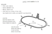
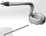
제한적이 아닌 예시의 목적으로, MIRTH 시술에 사용하도록 설계된 이식체가 본 명세서에서 설명되고 도 1에 도시되어 있다. MIRTH 이식체는, 루프를 형성하는 두 개의 단부(두 개의 단부를 가지는 "방사선 불투과성 봉합사"로 도시됨)을 가지는 신장형 가요성 테더(tether) 및, 테더의 두 개의 단부에 배치된 잠금부 몸체를 가지는 조정 가능 잠금부를 포함한다. 잠금부 몸체는, 미국 특허 제10,433,962호에 도시된 것과 유사한 메커니즘 및 잠금부 전달 카테터(lock delivery catheter)를 사용하여 신장형 가요성 테더를 해제 가능하게 속박하도록 구성될 수 있다. 이식체는 도시된 바와 같이 제1 및 제2 관형 가지부(tubular limb)를 더 포함하는데, 이 가지부는 루프를 따라 서로를 향해 신장형 가요성 테더 위의 잠금부로부터 바깥쪽으로(도시된 바에 따르면, 아래쪽으로) 연장한다. 도시된 바와 같이, 각각의 가지부는 잠금부 몸체를 빠져나간 직후 대략 90도로 굽혀져서 주변 해부학적 구조에 대해 잠금부와 가지부가 적절하게 정렬되기 쉽게 한다. 이식체 잠금부는, 내부에 적어도 하나의 원위 개구(distal opening)를 정의할 수 있다. 도시된 바와 같이, 적어도 하나의 원위 개구는 제1 및 제2 관형 가지부에 연결될 수 있다.For purposes of illustration and not limitation, an implant designed for use in the MIRTH procedure is described herein and shown in FIG. 1 . The MIRTH implant comprises an elongated flexible tether having two ends forming a loop (shown as a "radiopaque suture" having two ends) and locking portions disposed at the two ends of the tether. It includes an adjustable locking part having a body. The lock body may be configured to releasably constrain the elongate flexible tether using a lock delivery catheter and mechanism similar to that shown in U.S. Patent No. 10,433,962. The implant further includes first and second tubular limbs as shown, which limbs extend outward from the locking portion over the elongated flexible tether toward each other along the loop (as shown , downward) extend. As shown, each branch bends approximately 90 degrees immediately after exiting the lock body to facilitate proper alignment of the lock and branch relative to the surrounding anatomy. The implant lock may define at least one distal opening therein. As shown, at least one distal opening can be connected to the first and second tubular branches.
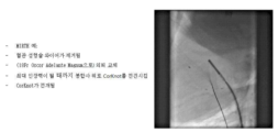
원하는 경우, 도시된 바와 같이, 제1 관형 가지부의 직경과 제2 관형 가지부의 직경은 다를 수 있다. 제1 및 제2 관형 가지부는 도 1에 도시된 바와 같이 점점 가늘어지는 원위 단부를 가질 수 있다. 도 3에 도시된 바와 같이, 가지부는 서로 접촉하고 중첩되기 시작할 때까지 봉합사를 따라 전진할 수 있다. 도 3에 도시된 바와 같이, 제1 관형 가지부의 원위 단부는, 제1 관형 가지부와 제2 관형 가지부가 겹치도록 신장형 가요성 테더의 루프를 따라 제2 관형 가지부의 원위 단부 안쪽으로 슬라이딩 이동할 수 있다. 제1 및 제2 관형 가지부 중 적어도 하나는, 그 길이를 따라 복수 개의 방사선 불투과성 마커를 포함할 수 있다. 필요한 경우, 내측 테더 또는 봉합사에는 일정한 간격으로 길이를 따라 방사선 불투과성 마커가 제공될 수도 있다. 예를 들어, 도 3에는 왼쪽에 있는 더 작은 직경의 가지부를 따라 제공되는 마커 밴드가 도시되어 있다. 복수 개의 방사선 불투과성 마커는, 시각화 하에서 이식체의 측정을 용이하게 하기 위해 도시된 바와 같이 소정의 패턴으로 상기 제1 및 제2 관형 기지부 중 적어도 하나의 길이를 따라 배치될 수 있다. 예를 들어, 시술할 때에 루프 이식체의 둘레 또는 길이를 추정하기 위해 필요할 수 있다. 추가로 또는 대안적으로 내측 테더를 따라 방사선 불투과성 마커를 포함함으로써 이를 달성할 수도 있다. 양 가지부는 마커 밴드를 포함할 수도 있음이 이해될 것이다.If desired, as shown, the diameter of the first tubular branch and the diameter of the second tubular branch may be different. The first and second tubular branches may have tapered distal ends as shown in FIG. 1 . As shown in Figure 3, the branches may be advanced along the suture until they contact each other and begin to overlap. 3 , the distal end of the first tubular branch can slide into the distal end of the second tubular branch along the loop of the elongated flexible tether such that the first and second tubular branches overlap. can At least one of the first and second tubular branches may include a plurality of radiopaque markers along its length. If desired, the inner tether or suture may be provided with radiopaque markers along its length at regular intervals. For example, FIG. 3 shows a marker band provided along the smaller diameter branch on the left. A plurality of radiopaque markers may be disposed along the length of at least one of the first and second tubular bases in a predetermined pattern as shown to facilitate measurement of the implant under visualization. For example, it may be necessary to estimate the circumference or length of a loop implant during a procedure. Additionally or alternatively, this may be accomplished by including a radiopaque marker along the inner tether. It will be appreciated that both branches may include marker bands.
구성 요소의 상대적인 위치를 파악하는 데 도움이 되도록 본 명세서에 설명된 임의의 이식체의 다른 구성 요소에도 마커 밴드를 포함하는 것이 유용하다. 그러나 본 발명에 따르면, 이러한 구성은 시술시 인장 테더에 인장력이 가해질 때 이식체가 수축되거나 조여지는 양을 의사가 정량화할 수 있도록 하기 위해 수행될 수도 있다. 예를 들어, 도시되어 있는 MIRTH 이식체의 경우, 이식체를 설치하는 의사는, 이식체를 소정의 위치에 놓고 가지부가 제공되는 잠금부를 인장 테더(들) 위로 그리고 환자의 심장으로 도입할 수 있다. 잠금부가 제자리에 배치되면, 잠금부 및/또는 안쪽 테더의 가지부의 마커 밴드의 상대적 위치를 알 수 있다. 그런 다음 잠금부를 통해 테더를 당겨서 테더에 장력을 인가하고 잠금부를 제자리에 유지시키면, 이식체의 둘레가 줄어들고 마커 밴드가 서로에 대해 이동한다. 소정 크기의 장력이 가해진 후 이식체를 잠글 수 있으며, 이식체가 원주 방향으로 얼마나 줄어들었는지도 알 수 있다. 또는, 이식체는 단순히 마커 밴드의 상대적인 위치를 참조하여 소정의 크기만큼 원주 방향으로 수축시킬 수 있다. 따라서 수술하는 의사가 원하는 거리만큼 축소되었음을 확인하면 잠금부를 그 위치에 배치하고 테더를 그 자리에 고정할 수 있다.It is useful to include marker bands on other components of any implant described herein to aid in the relative positioning of the components. However, according to the present invention, this configuration may also be performed to allow the surgeon to quantify the amount by which the implant shrinks or tightens when tension is applied to the tension tether during the procedure. For example, in the case of the MIRTH implant shown, the surgeon installing the implant may place the implant in place and introduce a lock provided with prongs over the tension tether(s) and into the heart of the patient. . Once the locks are in place, the relative positions of the locks and/or marker bands of the prongs of the inner tether are known. The tether is then pulled through the lock to apply tension to the tether and hold the lock in place, reducing the circumference of the implant and moving the marker bands relative to each other. After a certain amount of tension is applied, the implant can be locked, and how much the implant has shrunk in the circumferential direction can also be seen. Alternatively, the implant may simply be contracted circumferentially by a predetermined amount with reference to the relative positions of the marker bands. Therefore, when the operating surgeon confirms that the desired distance has been reduced, the locking part can be placed in that position and the tether fixed in place.
본 명세서에 개시된 바와 같이, 잠금부는 인장 요소의 자유 단부를 연결하고 인장 요소에 반대 견인력을 인가한다. 또한, 잠금부는 전달 및 조정을 위한 도크(dock)를 제공하며 다양한 구성을 취할 수 있다. 예를 들어, 도 1 내지 4의 MIRTH 이식체는 가지부와 결합된 위시본(wishbone) 형태를 갖는 것으로 도시되어 있지만, 그러한 형태가 아닐 수도 있다. 잠금부는 연장 가지부가 없는, 또는 도 8 내지 21의 실시예와 같이 단일 가지부를 포함하는 단일 테더 위로 미끄러질 수도 있다. 또는, 잠금부는 소망하는 경우 크림프(crimp)일 수도 있다. 유사하게, 잠금부는, 심근내 위치로부터 심외막 또는 우심방 위치로 장력을 변위시키는 "L"형 심근내 잠금부를 포함할 수 있다. 도 8 내지 21의 이식체는, 한 쌍의 테더 중 하나 위로 유사하게 전달될 수 있으며, 외측 관형 부재는 테더 중 하나 위로 부착되거나 다른 방식으로 밀릴 수 있고 양 테더는 잠금부를 통과할 수 있다.As disclosed herein, the lock connects the free end of the tensioning element and applies an opposing traction force to the tensioning element. The lock also provides a dock for delivery and adjustment and can take on a variety of configurations. For example, although the MIRTH implants of FIGS. 1 to 4 are shown as having a wishbone shape coupled with branch portions, they may not have such a shape. The locking portion may slide over a single tether without an extended limb or with a single limb as in the embodiments of FIGS. 8-21 . Alternatively, the locking portion may be crimped if desired. Similarly, the lock may include an “L” shaped intramyocardial lock that displaces tension from an intramyocardial position to an epicardial or right atrial position. The implants of Figures 8-21 can similarly be delivered over one of a pair of tethers, the outer tubular member can be attached or otherwise pushed over one of the tethers and both tethers can pass through a fastener.
예를 들어, 도 3에 도시된 바와 같이, 오른쪽에 도시된 관형 가지부는 심장 조직을 자극하기 위해 내부에 형성된 복수 개의 페이싱 전극을 포함한다. 명시적으로 도시되지는 않았지만, 이식체는 페이싱, 제세동, 측정 및 제어 중 적어도 하나를 제공하기 위해 적어도 하나의 페이싱 전극에 결합된 제어기를 더 포함할 수 있다. 예를 들어, 제어기는 잠금부 몸체에 배치되거나 필요에 따라 잠금부 몸체에 결합될 수 있다. 원하는 경우, 신장형 가요성 테더는, 제어기로 신호를 전달하거나 제어기로부터의 신호를 전달받는 루프 안테나와 같은 안테나를 형성할 수 있다. 예를 들어, 루프 안테나 또는 다이폴 안테나와 같은 안테나를 형성하기 위해 하나 이상의 전도체가 봉합사 또는 테더에 내장될 수 있음을 이해할 것이다. 또는, 잠금부 몸체와 제1 및 제2 가지부에는, 제어기에 결합될 때 안테나로서 작용할 수 있는 하나 이상의 전도성 루프를 형성하는 전도성 경로가 제공될 수 있다.For example, as shown in FIG. 3 , the tubular branch shown on the right includes a plurality of pacing electrodes formed therein for stimulating cardiac tissue. Although not explicitly shown, the implant can further include a controller coupled to the at least one pacing electrode to provide at least one of pacing, defibrillation, measurement and control. For example, the controller may be disposed on the lock body or coupled to the lock body as needed. If desired, the elongated flexible tether may form an antenna, such as a loop antenna, that carries signals to or receives signals from the controller. It will be appreciated that one or more conductors may be embedded in the suture or tether to form an antenna such as, for example, a loop antenna or dipole antenna. Alternatively, the lock body and the first and second limbs may be provided with conductive pathways forming one or more conductive loops capable of acting as antennas when coupled to the controller.
일부 실시예에서, 페이싱 장치는 MIRTH 궤적을 따라 기저 좌심실 심근(basal left ventricular myocardim) 내부 깊숙이 효과적으로 이식되는 링 전극 어레이(ring electrode array)를 포함할 수 있어 원하는 기저-정점 순서(base-to-apex sequence)로 건강하거나 병든 심근의 동시 활성화(다르게는 탈분극(depolarization))을 가능하게 할 수 있다. 링 전극은 단극 또는 다극 구성으로 되어 있는 (예를 들어, 1, 2 또는 3mm 간격의) 다중 전극을 포함할 수 있다. 전체 배열은 심근 깊이 이식되는데, 이는 수술이나 심외막 또는 심내막 이식으로는 달성할 수 없다.In some embodiments, the pacing device may include a ring electrode array that is effectively implanted deep inside the basal left ventricular myocardim along the MIRTH trajectory to achieve a desired base-to-apex sequence. sequence) can enable simultaneous activation (or alternatively depolarization) of healthy and diseased myocardium. The ring electrode may include multiple electrodes (eg spaced 1, 2 or 3 mm apart) in a monopole or multipole configuration. The entire array is implanted deep in the myocardium, which cannot be achieved by surgery or epicardial or endocardial implantation.
우심실 페이싱으로 인한 비동기화의 문제는 전체 기저 좌심실의 동시 탈분극(depolarization)에 의해 해결된다. (위치, 섬유증, 이종 심근병증, 가변 표적 정맥 위치로 인한) 신뢰할 수 없는 캡쳐 및 표준 좌심실 리드(standard left ventricular leads)를 사용한 재동기화의 문제점은, MIRTH 위치를 따라 깊은 기저 원주 링 전극을 이식하여 해결된다. 직접 His-다발 페이싱 전극(direct His-bundle pacing electrodes)의 물리적 리드 불안정성(physical lead insecrurity) 문제는, 깊이 이식된 어레이 전극을 사용하여 해결할 수 있다. 직접 His-다발 페이싱 전극의 가변적으로 높은 자극 임계값 문제는, 깊은 심근내 배열 전극을 사용하여 해결할 수 있다. 심장 박동기 리드를 사용하여 의도치 않게 삼첨판 역류를 유발하는 문제는, 깊은 MIRTH 전극 어레이를 사용하여 해결할 수 있다. 삼첨판 역류를 유발할 수 있는 부피가 크고 불안정한 제세동(defibrillation) 전극의 문제는, 깊은 MIRTH 전극 어레이를 사용하여 해결할 수 있다. 기존 페이싱/제세동 리드와의 조직 및 판막 상호 작용으로 인한 심내막염 문제는 깊은 MIRTH 전극 어레이로 완화된다.The problem of desynchronization due to right ventricular pacing is resolved by simultaneous depolarization of the entire basal left ventricle. Problems with unreliable capture (due to location, fibrosis, heterogeneous cardiomyopathy, variable target vein location) and resynchronization using standard left ventricular leads can be achieved by implanting deep basolateral circumferential ring electrodes along the MIRTH location. It is resolved. The problem of physical lead insecurity of direct His-bundle pacing electrodes can be solved by using deeply implanted array electrodes. The problem of variably high stimulation thresholds of direct His-bundle pacing electrodes can be addressed using deep intramyocardial array electrodes. The problem of inadvertently inducing tricuspid regurgitation with pacemaker leads can be addressed by using deep MIRTH electrode arrays. The problem of bulky and unstable defibrillation electrodes, which can cause tricuspid valve regurgitation, can be solved by using deep MIRTH electrode arrays. Endocarditis problems due to tissue and valve interactions with existing pacing/defibrillation leads are alleviated with deep MIRTH electrode arrays.
이식체에는 추가로 또는 대안적으로 유익한 작용제(beneficial agent)를 저장하는 저장소(미도시) 및 제어부가 제공될 수 있으며, 제어부는 유익한 작용제를 분배하기 위해 저장소에 연결되는 디스펜서(미도시)에 연결될 수 있다. 유익한 작용제는, 하나 이상의 약물, 유전자 치료 물질, 손상된 심장의 적어도 하나의 위치로 공급되는 살아있는 세포 등을 포함할 수 있다. 제1 및 제2 관형 가지부 중 적어도 하나는 적어도 하나의 생물학적 파라미터를 감지하기 위해 적어도 하나의 센서(미도시)를 포함할 수 있다. 센서는 예를 들어, 혈압을 감지하기 위한 압력 센서, 화학 센서, 거리 센서, 전기 생리학적 데이터를 검출하기 위한 회로를 갖는 센서, 움직임 센서 및 위치 센서 중 하나 이상을 포함할 수 있다.The implant may additionally or alternatively be provided with a reservoir (not shown) for storing a beneficial agent and a controller, the controller being connected to a dispenser (not shown) connected to the reservoir for dispensing the beneficial agent. can Beneficial agents may include one or more drugs, gene therapy substances, live cells supplied to at least one location in the damaged heart, and the like. At least one of the first and second tubular branches may include at least one sensor (not shown) for sensing at least one biological parameter. Sensors may include, for example, one or more of a pressure sensor to sense blood pressure, a chemical sensor, a distance sensor, a sensor with circuitry to detect electrophysiological data, a motion sensor, and a position sensor.
신장형 가요성 테더는 필요에 따라 그 길이를 따라 방사선 불투과성 재료를 포함할 수 있다. 신장형 가요성 테더는 중공 편조 봉합사(hollow braided suture)를 포함할 수 있고, 신장형 가요성 테더 내의 방사선 불투과성 물질은 신장형 내측 테더의 중공 코어 내에 존재하는 열수축 중합체 튜브의 길이를 따라 차례로 배치될 수 있는 방사선 불투과성 와이어를 포함할 수 있다. 추가적으로 또는 대안적으로, 편조 봉합사 소재는 분말 형태의 방사선 불투과성 분말 재료로 도핑될 수 있다. 조여지기 전의, 좌심실을 둘러싼 이식체의 상대적인 배향(orientation)은 도 4에 도시되어 있다.The elongated flexible tether may optionally include radiopaque material along its length. The elongate flexible tether may include a hollow braided suture, wherein the radiopaque material within the elongate flexible tether is sequentially disposed along a length of heat-shrinkable polymer tubing present within the hollow core of the elongate inner tether. A radiopaque wire may be included. Additionally or alternatively, the braided suture material may be doped with a radiopaque powder material in powder form. The relative orientation of the implant surrounding the left ventricle, prior to clamping, is shown in FIG. 4 .
추가 예로서, 이식체를 인장시키고 제자리에 고정시키는 데 사용되는 내측 테더는 DSM, Dyneema 또는 Teleflex의 1-2mm 초고분자량 폴리에틸렌("UHMWPE") 코어리스 라운드 브레이드(coreless round braid)로 만들 수 있다. 일부 구현예에서, 인장 테더는 방사선 불투과성을 향상시키기 위해 적어도 20중량%의 비스무트를 포함할 수 있다. 예를 들어, 인장 테더는 약 20 내지 약 70%의 비스무트 또는 황산바륨 또는 약 1중량%의 단위로 상기 범위 사이의 임의의 비율로 포함될 수 있다. 텅스텐, 탄탈룸 및 황산바륨과 같은 추가 또는 대체 방사선 불투과성 소재가 인장 테더 또는 이식체의 다른 부분 또는 전달 장치 또는 본 명세서에 기재된 다른 기구에 통합될 수 있다. 이들 소재는 예를 들어 직조에 의해 또는 인발 와이어를 테더 내에 정의된 중앙 채널을 따라 향하게 하는 등의 방법에 의해, 편조에 통합된 인발 금속(예를 들어, 백금 또는 기타 방사선 불투과성 재료) 와이어로서 통합될 수 있다. 추가의 실시예에서, 초고분자량 폴리에틸렌은 개선된 크리프(creep) 저항을 위한 인장 테더 재료로서 사용될 수 있고, 바람직하게는 1-2mm 크기이고, Teleflex Corporation으로부터 상업적으로 입수가능하다. 인장 테더에 대해 편조 재료가 예시되어 있지만, 임의의 다른 적합한 재료도 사용될 수 있음이 이해된다.As a further example, the inner tether used to tension and hold the implant in place may be made from 1-2 mm ultra high molecular weight polyethylene ("UHMWPE") coreless round braid from DSM, Dyneema or Teleflex. In some embodiments, the tensile tether can include at least 20% by weight of bismuth to enhance radiopacity. For example, the tensile tether may include from about 20 to about 70% bismuth or barium sulfate or any percentage between the above ranges in units of about 1% by weight. Additional or alternative radiopaque materials such as tungsten, tantalum, and barium sulfate may be incorporated into the tension tether or other portion of the implant or delivery device or other device described herein. These materials can be as drawn metal (e.g., platinum or other radiopaque material) wires incorporated into a braid, for example by weaving or by directing the drawn wire along a central channel defined within the tether. can be integrated In a further embodiment, ultra-high molecular weight polyethylene can be used as the tensile tether material for improved creep resistance, preferably 1-2 mm in size, and commercially available from Teleflex Corporation. Although a braided material is illustrated for the tensile tether, it is understood that any other suitable material may be used.
추가 구현예에서, 인장 요소는 본 명세서에 기재된 바와 같은 편조 봉합사, 또는 외측 관형 부재 내에 배치된 방사선 불투과성 코어를 포함하는 코어 부재가 제공되는 다른 외측 관형 부재를 포함할 수 있다. 이것은 방사선 불투과성 재료를 포함하는 단선 또는 편조 와이어 또는 케이블, 또는 예를 들어 비스무트 또는 기타 방사선 불투과성 소재를 포함하도록 도핑되거나 변형된 더 작은 편조 테더를 포함할 수 있다.In further embodiments, the tensile element may include a braided suture as described herein, or other outer tubular member provided with a core member comprising a radiopaque core disposed within the outer tubular member. This may include solid or braided wire or cable comprising a radiopaque material, or smaller braided tethers doped or modified to include, for example, bismuth or other radiopaque material.
도 5a 내지 7b를 참조하여, 도시된 이식체의 이식 과정을 설명한다. 도 5a에는 하대정맥(Inferior Vena Cava; IVC)을 통해 관상정맥동(coronary sinus)에 접근하는 가이드 카테터를 도시한 도 5d의 일부 확대도가 도시되어 있다. 그런 다음 내비게이션 카테터는 관상정맥동의 관상 분지(coronary branch)에서 나오는 출구를 통해 사이 근육계(interstitial musculature)에 접근한다. 도 5b 및 5e에는, 가이드 카테터에 배치된 내비게이션 카테터가 도시되어 있는데, 좌심실 주위에 루프를 형성하기 위해 심근의 사이 공간 내부에서 이동한다. 그런 다음 내비게이션 카테터를 올가미 카테터에 끼우고 가이드 카테터로 빼내어 온전한 루프를 형성한다. 그런 다음 내비게이션 카테터의 양쪽 끝을 외부화(externalize)한다. 외부화된 내비게이션 카테터를 통과하는 유지 테더(retention tether)가, MIRTH 이식체의 가요성 테더 부분의 원위 단부에 부착된다. 그런 다음 MIRTH 이식체는 MIRTH 이식체의 가요성 테더 부분의 양쪽 끝이 외부화될 때까지 좌심실을 둘러싼 해부학적 조직으로 당겨진다. MIRTH 이식체를 제자리로 밀어 넣는데 도움이 될 수 있도록 푸시 카테터가 사용될 수 있다. MIRTH 이식체는, 각 단부로부터 연장하는 테더를 구비하는 가요성 본체를 포함하는 상기 도면에서, 양쪽 테더 단부가 외부화되어, 가지부가 부착된 잠금부가 MIRTH 이식체의 두 개의 단부 위로 통과할 수 있게 한다. MIRTH 이식체는 예를 들어, 직경이 커진 심실에 배치되는 두꺼운 중앙 부분이 있는 중공 편조 봉합사로 만들어진 가요성 루프를 포함할 수 있다. 이것은 예를 들어, 관형 부재와 같은 중실 가요성 몸체를 중공 테더에 삽입하여 두껍게 만들거나 아래에서 설명하는 다양한 기타 기술에 의해 수행될 수 있다. 이와 같이, MIRTH 이식체의 가요성 부분은 중앙 부분이 두꺼워진 연속 중공 봉합사로부터 형성될 수 있으며, 잠금부를 지나서 연장하는 테더 부분은 비어 있거나 그 안에 전도성 와이어와 같은 최소한의 구조적 요소를 가질 수 있으며, 잠금부를 지나 잠금부를 통과할 수 있으며 잠금부가 설치된 후에 잠금부 근처에서 절단될 수 있다. 따라서 도 5 내지 7에 도시된 바와 같이, 가이드와이어(도시되지 않음) 및 내비게이션 카테터에 의해, 필요한 경우 지지 카테터(support catheter)도 사용해서 통로가 생성되면, MIRTH 이식체는 점진적으로 가이드 카테터 안쪽으로 도입되어서 도 7a 및 7b에 도시된 바와 같은 최종 설치 상태가 된다.Referring to FIGS. 5A to 7B , the implantation process of the illustrated implant will be described. FIG. 5A is an enlarged partial view of FIG. 5D showing a guide catheter accessing a coronary sinus through the inferior vena cava (IVC). The navigation catheter then accesses the interstitial musculature through an exit from the coronary branch of the coronary sinus. 5b and 5e, a navigation catheter is shown placed on the guide catheter, which moves inside the interspace of the myocardium to form a loop around the left ventricle. The navigation catheter is then inserted into the snare catheter and withdrawn with the guide catheter to form a complete loop. Both ends of the navigation catheter are then externalized. A retention tether passing through the externalized navigation catheter is attached to the distal end of the flexible tether portion of the MIRTH implant. The MIRTH implant is then pulled into the anatomy surrounding the left ventricle until both ends of the flexible tether portion of the MIRTH implant are externalized. A push catheter may be used to help push the MIRTH implant into place. In the figure above the MIRTH implant includes a flexible body with tethers extending from each end, both tether ends being externalized so that locking parts with limbs attached can pass over the two ends of the MIRTH implant. . The MIRTH implant may include, for example, a flexible loop made of a hollow braided suture with a thick central portion placed over the enlarged diameter ventricle. This can be done, for example, by inserting a solid flexible body, such as a tubular member, into the hollow tether to thicken it, or by various other techniques described below. As such, the flexible portion of the MIRTH implant may be formed from a continuous hollow suture with a central thickening, and the tether portion extending beyond the locking portion may be hollow or may have minimal structural elements therein, such as conductive wires; It can pass through the lock through the lock and can be cut near the lock after the lock is installed. Thus, as shown in FIGS. 5 to 7 , once a passage is created by a guidewire (not shown) and a navigation catheter, using a support catheter if necessary, the MIRTH implant is gradually advanced into the guide catheter. introduced into the final installed state as shown in Figs. 7a and 7b.
도 8 내지 21에는, RAMIN 시술을 수행하기 위한 추가적인 이식체 및 관련 시술 방법이 도시되어 있다. 이러한 유형의 이식체 및 시술은 예를 들어 MIRTH 또는 SCIMITAR 시술에 사용할 수 있다. 본 명세서에서 설명된 이식체를 위한 통로를 생성하는 가이드와이어 궤적을 설정하기 위해 사용될 수 있는 특정 예시 과정에 관하여 이후에 상세하게 설명되므로 여기서는 상세하게 설명하지 않는다.8-21, additional implants and associated surgical methods for performing the RAMIN procedure are shown. Implants and procedures of this type can be used, for example, in MIRTH or SCIMITAR procedures. Specific exemplary procedures that may be used to establish a guidewire trajectory that creates a passage for an implant described herein are described in detail later and will not be described in detail herein.
그러나 일단 가이드와이어 궤적이 설정되면, 인장 요소 또는 이식체는 전달되고 배치된 후에, 대상 심근의 기하학적 구조를 변경하기 위해 짧아져야 한다. 심근 조직은 기둥 강도(column strength), 장력 및 윤활성의 조합을 요구하는 전달에 대해서 저항을 생성한다. 일단 전달되면, 인장 요소는 까짐(erosion) 또는 "치즈 컷팅(cheese cutting)"을 저감시키고 길이를 줄이기 위해 직경을 확장하도록 조작될 수 있는 것이 바람직하다. 원하는 경우, 가이드와이어에 의해 정의된 통로를 확장하는 데 도움이 되는 지지 카테터(들)는, 식염수를 주입할 수 있는 유체 출구 포트로 강화되어 국부적 가압 영역을 생성함으로써 심근을 무딘 절개(blunt dissection)하는데 도움이 되는 수력절제(hydrodissection)를 가능하게 하고, 또한, 윤활도를 높여서 통로 확장에 도움이 된다.However, once the guidewire trajectory is established, the tensile element or implant must be shortened to change the geometry of the target myocardium after it has been delivered and deployed. Myocardial tissue creates resistance to transmission which requires a combination of column strength, tension and lubricity. Once delivered, the tensile element can preferably be manipulated to expand its diameter to reduce length and reduce erosion or "cheese cutting". If desired, the support catheter(s), which help dilate the passageway defined by the guidewire, are reinforced with a fluid exit port through which saline can be injected to create a localized pressurized area, thereby blunt dissection of the myocardium. It enables hydrodissection, which helps to improve lubrication, and also helps to enlarge the passageway by increasing lubrication.
절제 요소의 두께와 관련하여, 통로는 0.014-0.035인치의 가이드와이어에서 시작하여 바람직하게는 2-3mm 두께의 이식체를 수용하도록 확장된다. 바람직하게는 이식체는 길이 마커(예를 들어, 방사선 불투과성 마커)를 갖는다. 유사하게, 이식체의 직경은 아래에서 설명하는 바와 같이 이식할 때 증가할 수 있다. 이식체가 까짐(erosion); 당김(pull-through); 및 심근 열상을 방지하도록 하는 것은, 구불구불한 심근 궤적으로 이식체를 전달하는 동안 중격-후방 SCIMITAR 시술 및 SCIMITAR 시술에서 전방 재진입 등의 곡선 주변에서 특히 중요하다.Regarding the thickness of the ablation element, the passageway starts at a guidewire of 0.014-0.035 inches and preferably expands to accommodate implants of 2-3 mm thickness. Preferably the implant has a length marker (eg a radiopaque marker). Similarly, the diameter of the implant may increase upon implantation as described below. erosion of the implant; pull-through; and preventing myocardial laceration is especially important around curves such as posterior-septal SCIMITAR procedures and anterior re-entry in SCIMITAR procedures during implant delivery with tortuous myocardial trajectories.
제한이 아닌 예시의 목적으로, 도 10에는 근위 단부 및 원위 단부를 갖는 신장형 내측 테더를 포함하는 이식체가 도시되어 있다. 신장형 내측 테더의 근위 단부는 도시된 바와 같이 루프로 종료될 수 있다. 이식체는 외측 관형 몸체(도 10 및 11에 루프 테더를 둘러싸는 두꺼운 선으로 표시)를 포함할 수 있는데, 이 몸체는 내측 테더 길이의 적어도 일부를 따라 신장형 내측 테더를 둘러싸고 있다. 외측 관형 몸체는 신장형 내측 테더보다 길이가 짧을 것으로 예상할 수 있다. 아래에 설명된 바와 같이, 도시된 이식체는 축 방향을 따라 압축될 때 길이는 짧아지고 횡방향 치수는 증가하도록 구성될 수 있다.For purposes of illustration and not limitation, FIG. 10 shows an implant comprising an elongated inner tether having a proximal end and a distal end. The proximal end of the elongated inner tether may terminate in a loop as shown. The implant may include an outer tubular body (indicated by the thick line surrounding the loop tether in FIGS. 10 and 11 ), which body encloses the elongate inner tether along at least a portion of the inner tether length. The outer tubular body can be expected to be shorter in length than the elongated inner tether. As discussed below, the implant shown may be configured to shorten in length and increase in transverse dimension when compressed along the axial direction.
도 8 내지 15에 도시된 바와 같이, 도시된 이식체를 이식하는 관련 시술은, 일반적으로 하나 이상의 지지 카테터를 사용하거나 해서 이식체를 수용하기 위한 통로를 정의하기 위해 본 명세서에 개시된 바와 같은 절제 시술로 시작할 것이다. 도 8 및 9에는 전기 가이드와이어 또는 다른 절제 카테터를 지지하고 둘러싸는 지지 카테터(예를 들어, Navicross)에 의해 정의된 통로가 도시되어 있으며, 이는 아래에서 더 상세히 설명된다. 도 9에 도시된 바와 같이, 가이드와이어의 원위 단부와 지지 카테터는 캡쳐되고 외부화된다.As shown in FIGS. 8-15 , a related procedure for implanting the depicted implant is an ablation procedure as disclosed herein to define a passageway for receiving the implant, typically using one or more support catheters or the like. will start with 8 and 9 show a passageway defined by a support catheter (eg Navicross) supporting and surrounding an electrical guidewire or other ablation catheter, which is described in more detail below. As shown in Figure 9, the distal end of the guidewire and support catheter are captured and externalized.
그 다음에, 도 10 및 11에 도시된 바와 같이, 이식체의 외측 관형 부재 내부의 인장 테더의 원위 단부는, 예를 들어 지지 카테터에 남아 있는 가이드와이어에 인장 테더를 단순히 부착함으로써 지지 카테터를 통해 인출된다. 그런 다음 가이드와이어는, 가이드와이어를 구비하는 이식체의 인장 테더를 따라 당기면서 지지 카테터를 통해 빼내어진다. 원하는 경우, 이식체의 코어를 형성하는 인장 테더와 함께, "유지" 테더(retention tether)의 원위 단부도 가이드와이어에 부착하고 인장 테더와 함께 지지 카테터를 통해 인출될 수 있다. 유지 테더의 근위 단부는 외측 관형 부재의 원위 단부에 부착될 수 있다. 이렇게 하면 인장 테더가 지지 카테터로 인출될 수 있다. 그러나 유지 카테터는 외측 관형 부재의 원위 단부를 잡아당겨서 지지 카테터가 인출될 때 이를 환자의 혈관계(vasculature)로 끌어당긴다. 이는 인장 테더가 외측 관형 부재를 당기는 데 사용될 필요가 없도록 하는데, 만약 그렇게 구성되면 외측 관형 부재가 짧아지고 확장될 수 있다. 그런 다음 외측 관형 부재는 인장 테더를 잡아당겨서 나중에 확장될 수 있지만, 외측 관형 부재가 심장으로 이송되는 동안에는 확장되지 않는다.Then, as shown in FIGS. 10 and 11 , the distal end of the tension tether inside the outer tubular member of the implant is passed through the support catheter, for example by simply attaching the tension tether to a guidewire remaining in the support catheter. are withdrawn The guidewire is then withdrawn through the support catheter while pulling along the tension tether of the implant with the guidewire. If desired, with the tension tether forming the core of the implant, the distal end of the "retention" tether can also be attached to the guidewire and drawn through the retention catheter together with the retention tether. A proximal end of the retention tether may be attached to a distal end of the outer tubular member. This allows the tension tether to be drawn into the support catheter. However, the retention catheter pulls on the distal end of the outer tubular member, pulling it into the patient's vasculature when the retention catheter is withdrawn. This eliminates the need for a tension tether to be used to pull the outer tubular member, which if so configured can be shortened and extended. The outer tubular member can then be expanded later by pulling on the tension tether, but not during transport of the outer tubular member to the heart.
따라서, 주로 유지 카테터에 의해 부여된 장력 덕분에, 외측 관형 부재는 외부화된 지지 카테터의 원위 단부에 맞닿도록 당겨질 수 있고, 지지 카테터는 인출될 수 있어, 이식체의 외측 관형 부재를 당긴다. 도 11에 도시된 바와 같이, 인장 테더의 원위 단부는 자체 근위 단부에 의해 형성된 근위 루프를 통해 안내될 수 있다. 도 12 및 13에는 심장으로 당겨지는 인장 테더의 루프가 도시되어 있다. 이 때 이식체는 도 13 및 14에 도시된 바와 같이 레일 역할을 하는 단일 인장 테더 위로 잠금부 전달 카테터를 통과시켜 조일 수 있다. 도 15에 도시된 바와 같이, 예를 들어 미국특허 제10,433,962호에 설명된 바와 같이, 절단 카테터를 사용해서 잉여 테더를 자를 수 있다.Thus, thanks primarily to the tension imparted by the retention catheter, the outer tubular member can be pulled against the distal end of the externalized support catheter, and the support catheter can be withdrawn, pulling the outer tubular member of the implant. As shown in FIG. 11 , the distal end of the tension tether can be guided through a proximal loop formed by its own proximal end. 12 and 13 show loops of tension tether being pulled to the heart. The implant can then be tightened by passing the locking delivery catheter over a single tension tether that serves as a rail, as shown in FIGS. 13 and 14 . As shown in FIG. 15 , the excess tether may be cut using a cutting catheter, as described, for example, in U.S. Patent No. 10,433,962.
도 1의 이식체 실시예의 내측 인장 테더에는 근위 루프가 유사하게 제공될 수 있는데, 외부화될 때에 근위 루프는 [이식체를 전달하고, 단일 테더를 구비하는 잠금부 몸체를 통과하는 하나의 테더 단부에 장력이 인가되도록 장력을 인가하는] 카테터의 근위 단부 위로 루프를 형성한다는 점이 이해될 것이다. 더욱이, 잠금부 몸체는 도 12 및 13에 도시된 단일 인장 테더 위로 유사하게 전진될 수 있다는 점이 이해될 것이다.The inner tension tether of the implant embodiment of FIG. 1 can be similarly provided with a proximal loop, which when externalized proximal loop [at one tether end passing through the lock body carrying the implant and having a single tether]. It will be appreciated that tension is applied to form a loop over the proximal end of the catheter. Moreover, it will be appreciated that the lock body can be similarly advanced over the single tension tether shown in FIGS. 12 and 13 .
외측 관형 부재가 심장 또는 다른 해부학적 구조를 통과하는 통로에 배치된 후 직경이 확장되도록 다양한 장치가 사용될 수 있다. 예를 들어, 도 16에 도시된 바와 같이, 인장 테더("이식체 테더"로 도시됨)는 외측 관형 부재가 도입될 때 느슨하게 이식체 안팎으로 통과할 수 있다. 유지 테더는 외측 관형 부재의 원위 단부에 결합되는 것으로 도시되어 있다. 그 다음에 테더는 외측 관형 부재가 배치된 후에 인장될 수 있다.A variety of devices may be used to expand the diameter of the outer tubular member after it is placed in a passage through the heart or other anatomical structure. For example, as shown in FIG. 16 , a tension tether (shown as “implant tether”) can pass loosely into and out of the implant as the outer tubular member is introduced. A retaining tether is shown coupled to the distal end of the outer tubular member. The tether can then be tensioned after the outer tubular member is placed.
도 17a-17c에 도시된 바와 같이, 외측 관형 몸체는 편조 구조를 포함할 수 있다. 도 16, 20 및 21에 도시된 바와 같은 일부 구현예에서, 신장형 내측 테더는 외측 관형 본체를 띄엄띄엄 통과한다. 보다 구체적으로는, 보이는 바와 같이, 신장형 내측 테더는 먼저 폭을 가로질러 이식체를 통과하도록; 그 다음 이식체의 한쪽 표면을 따라서; 그 다음 다시 반대 방향으로 폭을 가로지르도록 이식체를 통과하고; 이어서 같은 방식으로 이식체를 따르고 통과하게 된다. 도시된 바와 같이, 테더의 이러한 패턴은 구형파(square wave)를 형성할 수 있고, 또는 예를 들어 정현파이거나 톱니 형태를 형성할 수도 있다. 이것은 이식체가 순응도(compliance)를 가지도록 할 수 있고, 이식체가 심장의 움직임에 응답하여 길이가 변경하는 것을 허용할 수 있다. 특히, 신장형 내측 테더의 경로가 이식체의 폭을 가로질러 반복적으로 지나가는 방식이므로, 이식체 몸체를 통과하는 테더의 길이는 실제로 이식체 몸체의 길이보다 상당히 길다는 것을 알 수 있다. 도 20의 이식체는 이식체 몸체 길이가 수축되지 않은 상태로 도시되어 있다. 테더가 당겨지면, 도 21에 도시된 바와 같이 이식체의 길이는 줄어들고 두께는 증가하게 된다. 이식체 몸체의 강성 뿐만 아니라 테더가 이식체 몸체를 통과하는 방식에 따라서 이식체의 길이를 따라 다양한 형태가 만들어질 수 있다. 예를 들어, 이식체 몸체는 이식체 몸체의 길이를 따라 서로 다른 경도 및/또는 두께를 가지는 소재를 포함하는 다층 구조로 형성될 수 있다. 금속 또는 기타 필라멘트의 편조는 편조 층을 형성할 수 있으며, 편조(braiding)는 예를 들어 잘 구부러지지 않도록 되어 있는 영역에서는 더 조밀할 수 있다. 이식체에서 거의 편조된 영역 또는 거의 강성인 영역은, 축 방향을 따른 이식체의 붕괴 및 반경 방향을 따른 이식체의 팽창을 용이하게 하기 위해 일반적으로 테더의 경로와 정렬될 수 있다. 당겨진 경우에도 테더는 여전히 이식체 몸체보다 길며, 이식체 몸체의 압축성과 유연성으로 인해, 설치된 이식체가 휘어지고 심장 박동을 수용할 수 있는 유효 길이로 조정될 수 있다. 원하는 경우, 이식체 몸체는, 인접 영역이 서로 다른 강성을 가지도록 만들 수 있는데, 예를 들어, 스트링의 비드(bead)와 유사한 방식으로 서로 분리되며 서로 다른 길이를 가지는 강성이 더 큰 소재를 내부 층 주위에 포함하는 가요성 내부 층으로 만들 수 있다. 이식체 길이를 줄이면 강성이 큰 재료 영역이 서로를 향해 이동하여 그 사이에 있는 유연한 내부 재료 층이 압축될 수 있다.As shown in FIGS. 17A-17C , the outer tubular body may include a braided structure. In some embodiments, as shown in Figures 16, 20 and 21, the elongate inner tether intermittently passes through the outer tubular body. More specifically, as shown, the elongated inner tether is first passed across the width and through the implant; then along one surface of the implant; then through the implant again across the width in the opposite direction; It is then followed and passed through the implant in the same manner. As shown, this pattern of the tether can form a square wave, or it can form a sine wave or sawtooth, for example. This can allow the implant to have compliance and allow the implant to change length in response to heart movements. In particular, it can be seen that the length of the tether passing through the implant body is actually significantly longer than the length of the implant body, since the path of the elongated inner tether is such that it repeatedly passes across the width of the implant body. The implant of FIG. 20 is shown with the implant body length unretracted. When the tether is pulled, the length of the implant decreases and the thickness increases, as shown in FIG. 21 . Various shapes can be made along the length of the implant depending on the stiffness of the implant body as well as the way the tether passes through the implant body. For example, the implant body may be formed of a multi-layered structure including materials having different hardness and/or thickness along the length of the implant body. Braiding of metal or other filaments may form a braided layer, and the braiding may be denser, for example in areas where it is not intended to bend easily. A substantially braided or substantially rigid region in the implant can generally be aligned with the path of the tether to facilitate collapse of the implant along the axial direction and expansion of the implant along the radial direction. Even when pulled, the tether is still longer than the implant body, and the compressibility and flexibility of the implant body allows the installed implant to bend and adjust to an effective length to accommodate a heartbeat. If desired, the implant body can be made such that adjacent regions have different stiffnesses, for example, a stronger material of different lengths separated from each other in a manner similar to the beads of a string is internally incorporated. It can be made with a flexible inner layer that includes around the layer. Reducing the length of the implant can cause regions of the more rigid material to move toward each other, compressing the flexible inner material layer between them.
일부 구현예에서, 외측 관형 몸체는 탄성 부재를 포함할 수 있다. 원하는 경우, 외측 관형 몸체는 형상 기억 소재, 탄성 부재 및/또는 코일 스프링을 포함할 수 있다. 일부 구현예에서, 외측 관형 몸체는 길이를 따라 복수의 방사선 불투과성 마커를 포함할 수 있다. 외측 관형 몸체의 길이를 따라 배치된 복수 개의 방사선 불투과성 마커는 가시화된 이식체의 측정을 용이하게 하기 위해 미리 정해진 간격으로 배치될 수 있다.In some embodiments, the outer tubular body can include an elastic member. If desired, the outer tubular body may include shape memory material, resilient members and/or coil springs. In some embodiments, the outer tubular body can include a plurality of radiopaque markers along its length. A plurality of radiopaque markers disposed along the length of the outer tubular body may be disposed at predetermined intervals to facilitate measurement of the visualized implant.
MIRTH 이식체에서와 같이, 도 8 내지 21에 도시된 이식체의 외측 관형 몸체는, 심장 조직을 자극하기 위한 적어도 하나의 페이싱 전극을 포함할 수 있다. 전도계 질환, 특히 허혈성 또는 비허혈성 심근병증에서의 전도계 질환으로 인한 비동기 수축이 있을 때 심장을 재동기화하기 위해 심장 둘레 또는 심장 일부 주변에 4개, 8개 또는 12개와 같이 불연속적인 개수로 조합된 페이싱 전극이 사용될 수 있다. 원하는 경우, 이식체는 페이싱, 제세동, 측정 및 제어 중 적어도 하나를 제공하기 위한 적어도 하나의 페이싱 전극에 결합된 제어기(예를 들어, 잠금부 몸체에 내장됨)를 더 포함할 수 있다. 도 8 내지 21에 도시된 이식체는, 제어기로 신호를 전달하거나 및 제어기로부터의 신호를 전달하는 루프 안테나, 다이폴 안테나, 모노폴 안테나, 헬릭스 안테나 등과 같은 안테나를 포함할 수 있다. 원하는 경우, 도 8 내지 21에 도시된 이식체는, 제어기 및 유익한 제제를 수용하는 저장소(미도시)를 포함할 수 있다. 제어기는 유익한 제제를 분배하기 위해 저장소에 연결된 분배기(미도시)에 결합될 수 있다. 원하는 경우, 유익한 제제는, 손상된 심장의 적어도 하나의 위치로 공급되는 약물, 유전자 치료 물질 및 살아 있는 세포 중 하나 이상을 포함할 수 있다. 원하는 경우, 도 8 내지 21에 도시된 이식체의 외측 관형 몸체는 적어도 하나의 생물학적 파라미터를 감지하기 위한 적어도 하나의 센서를 포함할 수 있다. 적어도 하나의 센서는 혈압을 감지하기 위한 적어도 하나의 압력 센서를 포함할 수 있다. 적어도 하나의 센서는 화학 센서, 거리 센서, 전기 생리학적 데이터를 검출하는 회로를 갖는 센서, 움직임 센서 및 위치 센서 중 적어도 하나를 포함할 수 있다. 신장형 내측 테더는 중공 편조 봉합사일 수 있고, 신장형 내측 테더 내의 방사선 불투과성 소재는 신장형 내측 테더의 중공 코어 내에 존재하는 열수축 중합체 튜브의 길이 내에 배치된 방사선 불투과성 와이어를 포함할 수 있다.As with the MIRTH implant, the outer tubular body of the implant shown in FIGS. 8-21 may include at least one pacing electrode for stimulating cardiac tissue. Combined in discrete numbers such as 4, 8 or 12 around the heart or around a portion of the heart to resynchronize the heart when there is asynchronous contraction due to conduction system disease, particularly in ischemic or non-ischemic cardiomyopathy. A pacing electrode may be used. If desired, the implant may further include a controller (eg, embedded in the lock body) coupled to the at least one pacing electrode for providing at least one of pacing, defibrillation, measurement and control. The implant shown in FIGS. 8 to 21 may include antennas such as loop antennas, dipole antennas, monopole antennas, helix antennas, etc. that transmit signals to and from the controller. If desired, the implant shown in FIGS. 8-21 may include a controller and a reservoir (not shown) containing a beneficial agent. A controller may be coupled to a dispenser (not shown) connected to the reservoir for dispensing the beneficial agent. If desired, the beneficial agent may include one or more of a drug, gene therapy material, and living cells delivered to at least one location in the damaged heart. If desired, the outer tubular body of the implant shown in FIGS. 8-21 may include at least one sensor for sensing at least one biological parameter. The at least one sensor may include at least one pressure sensor for sensing blood pressure. The at least one sensor may include at least one of a chemical sensor, a distance sensor, a sensor having circuitry to detect electrophysiological data, a motion sensor, and a position sensor. The elongate inner tether may be a hollow braided suture, and the radiopaque material within the elongate inner tether may include a radiopaque wire disposed within a length of heat-shrink polymeric tubing present within the hollow core of the elongate inner tether.
도 18 및 19에 도시된 바와 같이, 이식체의 내측 인장 테더 부분을 따라 배치된 전극 및 마커 밴드를 포함하는 이식체에 장력이 가해지면 이식체의 길이는 짧아지고 두께는 두꺼워진다. 도면으로부터 알 수 있는 바와 같이, 회로 경로는 내측 테더의 루프 경로를 통과해서 잠금부 몸체를 통해 나오며, 원하는 경우 잠금부를 작동하여 회로 경로를 완성하거나 회로가 이식체 내에서 완성될 수 있으며, 잠금부는 단순히 이식체를 함께 유지할 수 있다.As shown in FIGS. 18 and 19 , when tension is applied to the implant including electrodes and marker bands disposed along the inner tensile tether portion of the implant, the length of the implant shortens and the thickness increases. As can be seen from the figure, the circuit path passes through the loop path of the inner tether and exits through the body of the lock, if desired, the lock can be actuated to complete the circuit path or the circuit can be completed within the implant, the lock being You can simply keep the implant together.
추가로 본 발명에 따르면, 가지부 및 외측 관형 부재, 그리고 내측 인장 부재의 경도는 그 길이에 따라 가변적일 수 있다. 예를 들어, 심장의 외벽이 아닌 환자의 중격에 존재할 것으로 예상되는 가지부의 일부에 대해 심장의 외벽에 있는 부분과 다른 강성을 제공할 수 있다. 경도의 변화는 이식체의 길이에 따라 재료의 유형 또는 재료의 두께를 변경하여 달성할 수 있다. 추가로 또는 대안적으로, 인장 테더에 장력이 가해질 때 이식체 재료가 붕괴되는 방식에 따라 경도가 달라질 수 있다. 예를 들어, 도 16의 인장 테더의 파동의 간격은 이식체의 길이를 따라 가변적일 수 있어서, 조여지지 않은 외측 관형 부재의 단위 길이당 스티치 빈도가 외측 관형 부재의 다른 영역과 상이하다.Further according to the present invention, the hardness of the branch and outer tubular member and inner tension member may be variable along their length. For example, a part of a branch expected to be present in the patient's septum, which is not the outer wall of the heart, may be provided with a different stiffness than the part in the outer wall of the heart. Changes in hardness can be achieved by varying the type of material or thickness of the material along the length of the implant. Additionally or alternatively, the hardness can vary depending on how the implant material collapses when tension is applied to the tension tether. For example, the spacing of the undulations of the tensile tether of FIG. 16 can be variable along the length of the implant, such that the frequency of stitches per unit length of the untightened outer tubular member differs from other regions of the outer tubular member.
이식체는 이식체를 루프 형태로 잠그도록 구성된 이식체 잠금부를 더 포함할 수 있다. 잠금부를 체결하는 것과 같이 잠금부를 작동시키면 센서 또는 페이싱 장치를 활성화 및/또는 사용할 수 있도록 하는 전기 회로가 완성된다. 예를 들어, 내측 인장 테더는, 예를 들어 인장 테더에 압력을 가함으로써 이식체가 소정의 위치에 잠궈질 때 잠금부 몸체 내의 날카로운 미늘에 의해 관통되는 전기 절연층을 구비하는 다양한 도체 등을 포함할 수 있다. 잠금 과정 도중에 전도체에 압력을 가하면 잠금부 몸체 내의 돌출부 또는 미늘이 테더 내의 절연층을 관통하여 회로를 완성한다.The implant may further include an implant locking portion configured to lock the implant in a loop shape. Activating the lock, such as engaging the lock, completes an electrical circuit that enables and/or enables use of a sensor or pacing device. For example, the inner tension tether may include various conductors, etc. having an electrically insulating layer that is pierced by sharp barbs in the lock body when the implant is locked in position, for example by applying pressure to the tension tether. can During the locking process, when pressure is applied to the conductor, protrusions or barbs in the lock body pierce the insulating layer in the tether to complete the circuit.
일부 구현예에서, 본 명세서에 기재된 바와 같은 시술을 실시할 때 심근을 통과하도록 가이드와이어를 전진시키는 것은 조직을 절제하는 단계를 포함할 수 있다. 예를 들어, 심근 조직은, 가이드와이어를 통해 전기 에너지를 인가하여 전기적으로 절연되지 않은 (가이드와이어의 노출된) 원위 단부 표면에 전기 에너지를 공급함으로써 절제될 수 있다. 이것은, 가이드와이어 위로 지지 카테터를 전진시켜서 가이드와이어에 추가 컬럼 강도(additional column strength)를 제공하는 것에 일반적으로 동반한다. 가이드와이어의 원위 단부는, 시각화 모드에서 볼 수 있는 적어도 하나의 시각적으로 강화된 마커를 포함할 수 있다. 관련된 방법은, 심근 조직을 통한 가이드와이어의 전진을 제어하는 것을 돕는 시술을 하는 동안에, 시각화 모드에서 가이드와이어 및 심근을 시각화하는 것을 포함할 수 있다.In some embodiments, advancing the guidewire through the myocardium when performing a procedure as described herein may include ablating the tissue. For example, myocardial tissue can be ablated by applying electrical energy through a guidewire to an electrically non-insulated (exposed) distal end surface of the guidewire. This is usually accompanied by advancing the support catheter over the guidewire to provide additional column strength to the guidewire. The distal end of the guidewire may include at least one visually enhanced marker viewable in a visualization mode. A related method may include visualizing the guidewire and myocardium in a visualization mode during the procedure to help control advancement of the guidewire through the myocardial tissue.
제한이 아닌 설명을 위해, 도 22a-22d에는 본 발명에 따른 예시적인 가이드와이어 팁의 개략도가 도시되어 있다. 이러한 가이드와이어는 심근 탐색 및 횡단에 사용될 수 있다. 일단 심근에 진입하면, 가이드와이어는 조종되고 심장 근육을 통과하여 전진함으로써 다른 장치를 진입시키기 위한 바람직한 궤적 범위를 생성할 수 있다. 이는 조직 평면이 쉽게 횡단을 허용하지 않을 때 등각 전기 수술 진행(conformal electrosurgical advancement)을 가능하게 한다. 유니폴라 또는 바이폴라 RF 전력은 다양한 주파수에서 인가될 수 있다. 그러나, 본 발명에 따르면, 이러한 가이드와이어는 탐색을 안내하기 위해 심장내 전기도(intracardiac electrogram)의 기록 및 모니터링을 허용할 수 있는데, 이는 (심내막에서 심외막 사이의) 심근내 위치에 따라 서로 다른 특징적인 단극(unipolar) 및 양극(bipolar) 전기도(electrogram)를 보이기 때문이다.For purposes of illustration and not limitation, schematic diagrams of exemplary guidewire tips in accordance with the present invention are shown in FIGS. 22A-22D. These guidewires can be used for myocardial navigation and traversal. Once entered the myocardium, the guidewire can be maneuvered and advanced through the heart muscle to create a desirable trajectory range for entering other devices. This enables conformal electrosurgical advancement when tissue planes do not readily allow traversal. Unipolar or bipolar RF power can be applied at various frequencies. However, in accordance with the present invention, such a guidewire may allow recording and monitoring of an intracardiac electrogram to guide navigation, which may be correlated according to intramyocardial location (endocardiac to epicardium). This is because they show different characteristic unipolar and bipolar electrograms.
임의의 도시된 가이드와이어는 가이드와이어의 원위 팁에서 또는 그 근처에서 수액박리술 가스-절제(hydrodissection gas-dissection)를 허용하거나 여러가지 유익한 제제를 주입하기 위해 하이포튜브(hypotube)를 사용하는 것과 같은 신장형 통로와 함께 포함될 수 있다. 도시된 바와 같이, 도 22a-22d에는 비대칭 절연이 제공되어 심근 내부에 등각 전자기장(conformal electromagnetic fields)을 생성할 수 있다. 가이드와이어는 바람직하게는 0.014인치 직경의 폼 팩터에 부합하고 조종 가능한 고정 CTO 곡선을 가지며, 근위 단부 영역(예를 들어, 10mm)과 약 1mm의 원위 영역을 제외하고 전기적으로 절연된다. 팁(tip)은 도 22a(짙은 단부 지점)에 도시된 것처럼 대칭일 수 있지만, 구부러져서 조종이 가능할 수도 있다. 노출된 패치는 도 22b와 같이 원위 팁의 한쪽에 있을 수 있거나, 또는 비대칭 노출 패치가 도 22c에 도시된 바와 같은 원위 팁에 바로 인접하는 가까운 쪽에 배치될 수 있다. 도 22d에는 도 22b의 실시예를 전기외과적 절제를 위한 원위 모노폴(distal monopole)을 갖는 독립형 0.014" 마이크로 카테터와 결합한 개략도가 도시되어 있다. 도 22a-22c에 도시된 가이드와이어는, 선택한 작동 설정에서 연속 듀티 사이클 RF 절제를 위해 "절제" 버튼을 활성화할 수 있는 표준 전기수술기에 착탈 가능한 커넥터를 구비하는 키트에 결합될 수 있다.Any of the illustrated guidewires can be stretchable, such as using a hypotube to allow for hydrodissection gas-dissection at or near the distal tip of the guidewire or to inject various beneficial agents. Can be included with passages. As shown, asymmetric isolation can be provided in FIGS. 22A-22D to create conformal electromagnetic fields inside the myocardium. The guidewire preferably conforms to a 0.014 inch diameter form factor, has a steerable fixed CTO curve, and is electrically insulated except for a proximal end region (eg, 10 mm) and a distal region of about 1 mm. The tip can be symmetrical, as shown in FIG. 22A (dark end point), but can also be bent to allow steering. The exposed patch can be on one side of the distal tip as shown in FIG. 22B, or an asymmetric exposed patch can be placed on the proximal side immediately adjacent to the distal tip as shown in FIG. 22C. Figure 22D shows a schematic diagram combining the embodiment of Figure 22B with a stand-alone 0.014" microcatheter with a distal monopole for electrosurgical ablation. The guidewires shown in Figures 22A-22C are shown in selected operational settings. can be coupled to a kit with a removable connector to a standard electrosurgical machine capable of activating an “ablation” button for continuous duty cycle RF ablation.
심근에 접근하기 위해서는 일반적으로 가이드와이어가 길이 방향을 횡단한 후 조직으로 측면에서 진행하는 것이 필요하다. 심근에 대한 이러한 초기 접근을 위해 구심 접근 카테터(centripetal access catheter)를 사용할 수 있다. 이러한 기구의 예시적이고 비제한적인 실시예의 개략도가 도 23a-23c에 도시되어 있다. 기능적으로, 이 카테터는 가이드와이어의 원위 팁이 심근으로 정교하게 조정되도록 대상 위치를 향해 가이드와이어 위로 카테터를 전진시켜 사용된다. 따라서, 구심 접근 카테터는, 측면 접근 포트가 있는 폴리머 관형 부재로 만들어져서 가이드와이어의 방향을 바꿀 수 있다. 이것은, 가이드와이어를 먼저 심근에서 멀어지게 한 다음 가이드와이어를 180도 경로를 통해 안내하여 심근에 직접 들어가는 구불구불한 팁을 정의하는 구심 접근 카테터에 의해서도 달성할 수도 있다. 구심 접근 카테터는 구심 접근 카테터의 상대 회전 위치를 표시하는 방사선 불투과성 마커를 원위 단부 근처에 포함할 수 있어서, 심근에 진입하기 위한 가이드와이어의 올바른 배향이 되었을 때 의사가 인지할 수 있다. 바람직하게는, 구심 접근 카테터의 루멘(lumen)은 매끄럽고 전기적으로 절연되며, 그 외부 표면도 관상 정맥을 탐색하기 위해 매끄럽다. 원하는 경우, 가이드와이어 출구 포트 맞은 편에 있는 안내 카테터의 측면을 따라 팽창 가능한 요소가 제공되어서 루멘의 대향 측면에 반작용력을 제공할 수 있다. 따라서 구심 접근 카테터는 바람직하게는 전기 수술용 가이드와이어와 나란히 전진한다. 해부학적 위치 파악을 돕기 위해 혈관 조영 포트를 제공할 수 있으며, 구심 접근 카테터에는 바람직하게는 작은 프로필(예: 6-8 Fr)이 제공되어 관상 정맥동 풍선-팁 안내 외피(coronary sinus balloon-tip guiding sheath) 등의 더 큰 유도 카테터에도 맞을 수 있다. 도 23a에는 가이드와이어를 심근으로 안내하는 스위치백 경로를 따르는 가이드와이어 경로의 개략도가 도시되어 있다. 도 23b에는, LV에 대한 구심 카테터의 배향(단부 도면) 및 LV의 장축에서 본 카테터의 측면도가 도시되어 있다. 도 23c에는 측면에 가이드와이어 출구 포트를 구비하는 예시적인 카테터의 단면이 도시되어 있다.Access to the myocardium usually requires a guidewire to be traversed longitudinally and then laterally advanced into the tissue. A centripetal access catheter can be used for this initial access to the myocardium. A schematic diagram of an exemplary, non-limiting embodiment of such an instrument is shown in FIGS. 23A-23C. Functionally, this catheter is used by advancing the catheter over the guidewire towards a target location such that the distal tip of the guidewire is precisely tuned into the myocardium. Thus, the centripetal access catheter is made of a polymeric tubular member with a lateral access port to deflect the guidewire. This may also be achieved by a centripetal access catheter that first directs the guidewire away from the myocardium and then guides the guidewire through a 180 degree path to define a serpentine tip that enters the myocardium directly. The centripetal access catheter may include a radiopaque marker near the distal end indicating the relative rotational position of the centripetal access catheter, so that the surgeon can recognize when the correct orientation of the guidewire for entry into the myocardium has been achieved. Preferably, the lumen of the afferent access catheter is smooth and electrically insulated, and its outer surface is also smooth for navigating the coronary vein. If desired, an inflatable element may be provided along the side of the guide catheter opposite the guidewire exit port to provide a reaction force on the opposite side of the lumen. Thus, the centripetal access catheter is preferably advanced alongside the electrosurgical guidewire. An angiographic port may be provided to aid in anatomical localization, and the afferent access catheter is preferably provided with a small profile (e.g., 6-8 Fr) to avoid coronary sinus balloon-tip guiding sheaths. It can also fit larger guide catheters such as sheaths. 23A shows a schematic diagram of the guidewire path along the switchback path leading the guidewire to the myocardium. 23B shows the orientation of the centripetal catheter relative to the LV (end view) and a side view of the catheter viewed from the long axis of the LV. 23C shows a cross-section of an exemplary catheter with a guidewire exit port on the side.
본 발명은, 또한 카테터의 원위 단부 부근의 팽창 가능 부재 및 팽창 유체 저장소에 결합된 신장형 관형 부재, 및 팽창 가능 부재를 둘러싸는 컬랩서블 올가미(collapsible snare catheter)를 포함하는 카테터를 제공하며, 여기서 팽창 유체에 의한 팽창 부재의 팽창은 컬랩서블 올가미(collapsible snare)가 확장되게 한다. 컬랩서블 올가미는 단일 루프 올가미이다. 컬랩서블 올가미는 다중 루프 올가미일 수 있다. 컬랩서블 올가미는 팽창 부재가 수축된 후에도 개방 상태를 유지하도록 구성될 수 있다.The present invention also provides a catheter comprising an expandable member near the distal end of the catheter and an elongated tubular member coupled to an expandable fluid reservoir, and a collapsible snare catheter surrounding the expandable member, wherein: Inflation of the inflatable member by the inflation fluid causes the collapsible snare to expand. A collapsible lasso is a single loop lasso. A collapsible lasso can be a multi-loop lasso. The collapsible snare may be configured to remain open after the expandable member is deflated.
따라서, 본 발명에 의하면, 표적 위치에 올가미 카테터를 사용하여 가이드와이어의 원위 단부를 배치하는 단계를 포함하는 방법이 또한 제공되며, 여기서 올가미 카테터는 올가미 내부에 배치된 팽창 부재를 포함하고, 또한 팽창 부재의 팽창으로 인해 올가미가 확장된다. 이것은 주변 조직을 무딘절개(blunt dissection)함으로써 올가미를 위한 공간을 만들어서 수행될 수 있다. 풍선은 절개가 일어난 후에 수축될 수 있으며 다음으로 올가미 카테터는 가이드와이어를 캡쳐하고 접혀서 가이드와이어를 붙잡을 수 있다. 예를 들어, 이 가이드와이어 캡처 단계는 심근에서 수행될 수 있다. 유사하게 심근 외부에서 수행될 수도 있다. 신장형 통로는 가압 유체를 심근 내의 표적 위치로 향하게 함으로써 적어도 부분적으로 형성될 수 있다.Accordingly, according to the present invention there is also provided a method comprising deploying a distal end of a guidewire using a snare catheter at a target location, wherein the snare catheter includes an expandable member disposed within the snare, and is also inflated. The snare expands due to the expansion of the member. This can be done by making space for the snare by blunt dissection of the surrounding tissue. The balloon can be deflated after the incision has taken place and the snare catheter then captures the guidewire and is folded back to hold the guidewire. For example, this guidewire capture step can be performed in the myocardium. Similarly, it may be performed outside the myocardium. The elongate passageway may be formed at least in part by directing pressurized fluid to a target location within the myocardium.
본 발명은, 또한 근위 단부 및 원위 단부를 갖는 신장형 코어 부재와; 근위 단부 및 원위 단부를 갖고 신장형 코어 부재를 활주 가능하게 수용하기 위한 신장형 루멘(lumen)을 정의하는 신장형 중간 관형 부재와; 예를 들어, 근위 단부에서 신장형 중간 관형 부재의 원위 단부에 부착되고 원위 단부에서는 신장형 코어 부재의 원위 단부에 부착되는 복수 개의 편조 부재(braided member)로 형성된 컬랩서블 관형 천공 몸체를 포함하는 올가미 카테터를 제공하는데, 신장형 코어 부재의 원위 단부를 향한 신장형 중간 관형 부재의 원위 단부의 상대적 축방향 변위는 컬랩서블 관형 천공 몸체가 방사 방향 바깥쪽으로 확장하게 하고 편조 부재는 서로 분리되게 하며, 신장형 코어 부재의 원위 단부로부터 멀어지도록 하는 신장형 중간 관형 부재의 원위 단부의 상대적 축방향 변위는 컬랩서블 관형 천공 몸체가 반사 방향 안쪽으로 조여지게 하고 편조 부재도 함께 조여지도록 한다. 올가미 카테터는, 신장형 코어 부재를 따라 연장하고 신장형 중간 관형 부재에 부착된 근위 단부 및 신장형 코어 부재에 부착된 원위 단부를 구비하는 컬랩서블 관형 천공 몸체 내에 배치된 표적 와이어를 더 포함할 수 있다. 표적 와이어는, 컬랩서블 관형 몸체가 반경 방향 내측으로 조여질 때 일반적으로 직선인 제1 형태를 취하고, 컬랩서블 관형 천공 몸체가 반경 방향 외측으로 확장될 때 실질적으로 비선형인 제2 형태를 취하도록 구성될 수 있다. 올가미 카테터는, 근위 단부, 원위 단부를 구비하는 신장형 관형 길이방향 변위 가능 외피를 더 포함할 수 있는데, 이 외피는 신장형 루멘을 정의하며, 이 루멘은 컬랩서블 관형 천공 몸체가 일반적으로 방사 방향으로 조여진 상태일 때에 신장형 코어 부재와, 신장형 중간 관형 부재와, 컬랩서블 관형 천공 몸체 및 표적 와이어를 활주 가능하게 수용한다. 이러한 올가미 카테터의 특정 실시예는 예를 들어 미국 특허 제10,433,962호에 개시되어 있다.The present invention also relates to an elongate core member having a proximal end and a distal end; an elongate intermediate tubular member having a proximal end and a distal end and defining an elongate lumen for slidably receiving the elongate core member; For example, a snare comprising a collapsible tubular perforated body formed of a plurality of braided members attached at a proximal end to a distal end of an elongate intermediate tubular member and at a distal end attached to a distal end of an elongate core member. wherein relative axial displacement of the distal end of the elongate intermediate tubular member toward the distal end of the elongate core member causes the collapsible tubular perforated body to expand radially outward and the braided members to separate from one another; Relative axial displacement of the distal end of the elongate intermediate tubular member away from the distal end of the molded core member causes the collapsible tubular perforated body to be tightened in the reflection direction and the braided member to be tightened together. The snare catheter may further include a target wire disposed within the collapsible tubular puncture body extending along the elongate core member and having a proximal end attached to the elongate intermediate tubular member and a distal end attached to the elongate core member. there is. The target wire is configured to assume a first generally straight shape when the collapsible tubular body is tightened radially inward and a second substantially non-linear shape when the collapsible tubular perforated body is expanded radially outward. It can be. The snare catheter may further comprise an elongate tubular longitudinally displaceable sheath having a proximal end and a distal end, the sheath defining an elongate lumen wherein the collapsible tubular puncture body is generally radially displaceable. Slidably receives the elongate core member, the elongate intermediate tubular member, the collapsible tubular perforated body and the target wire when in a clamped state. A specific embodiment of such a snare catheter is disclosed, for example, in US Pat. No. 10,433,962.
원하는 경우, 올가미 카테터의 신장형 코어 부재는 가이드와이어 루멘을 형성하는 관형 부재일 수 있다. 올가미 카테터에는, 신장형 코어 부재의 원위 단부에 부착되는 순응성 소재(compliant material)로 형성된 비외상성 원위 팁(atraumatic distal tip)이 제공될 수 있다. 올가미 카테터(또는 본 명세서에 기재된 임의의 장치)는, 카테터의 원위 단부 및 신장형 중간 관형 부재의 원위 단부 부근에 배치된 방사선 불투과성 마커 밴드를 더 포함할 수 있다. 원하는 경우, 올가미 카테터는 표적 와이어에 형성된 복수의 방사선 불투과성 마커 밴드를 포함할 수 있다. 표적 와이어는 적어도 부분적으로 방사선 불투과성 재료로 형성될 수 있다. 컬랩서블 관형 천공 몸체는, 적어도 부분적으로 방사선 불투과성 소재로 형성될 수 있다.If desired, the elongate core member of the snare catheter may be a tubular member defining a guidewire lumen. The snare catheter may be provided with an atraumatic distal tip formed of a compliant material that is attached to the distal end of the elongate core member. The snare catheter (or any device described herein) may further include a radiopaque marker band disposed proximate the distal end of the catheter and the elongate intermediate tubular member. If desired, the snare catheter may include a plurality of bands of radiopaque markers formed on the targeting wire. The target wire may be at least partially formed of a radiopaque material. The collapsible tubular perforated body may be at least partially formed of a radiopaque material.
일부 구현예에서, 표적 와이어는 종방향으로 수축될 때 그 안에 형성된 적어도 하나의 루프 및/또는 파동(undulation)을 포함할 수 있다. 원하는 경우, 표적 와이어는, 종방향으로 수축될 때 그 안에 형성된 복수 개의 루프 및/또는 파동을 포함할 수 있다. 표적 와이어 및 루프(및/또는 파동)는 표적 와이어가 종방향으로 수축될 때 카테터의 길이방향 축에 평행한 단일 평면에 실질적으로 놓일 수 있다. 표적 와이어 및 루프(들) 및/또는 파동(들)은 표적 와이어가 종방향으로 수축될 때 3차원 형상을 정의할 수 있다. 원하는 경우, 표적 와이어가 종방향으로 수축될 때 하나 이상의 루프 및/또는 파동을 구비하는 복수의 표적 와이어가 제공될 수 있다. 표적 와이어는 제1 재료로 만들어진 코어 부분과, 제1 재료와는 다른 제2 재료로 만들어진 외피 부분(cladding portion)을 포함하는 와이어와 같은 복합 와이어를 포함할 수 있다.In some implementations, the target wire can include at least one loop and/or undulation formed therein when contracted longitudinally. If desired, the target wire may include a plurality of loops and/or undulations formed therein when contracted longitudinally. The target wire and loop (and/or wave) may lie substantially in a single plane parallel to the longitudinal axis of the catheter when the target wire is longitudinally retracted. The target wire and loop(s) and/or wave(s) may define a three-dimensional shape when the target wire is longitudinally contracted. If desired, a plurality of target wires may be provided having one or more loops and/or undulations when the target wires are longitudinally retracted. The target wire may include a composite wire, such as a wire including a core portion made of a first material and a cladding portion made of a second material different from the first material.
비제한적인 설명의 목적으로, 풍선 올가미 카테터가 도 24a-24b에 도시되어 있는데, 이 풍선 올가미 카테터는, 개시된 가이드와이어가 복귀해서 루프를 형성하면 재진입을 허용하고, 올가미 및 가이드와이어 팁이 심근 내부에 매립되어 있는 동안 이러한 가이드와이어를 이식체 구성요소로 회수, 외부화 및 교환할 수 있도록 한다.For purposes of non-limiting illustration, a balloon snare catheter is shown in FIGS. 24A-24B , wherein the balloon snare catheter allows re-entry once the disclosed guidewire is returned to form a loop, and the snare and guidewire tip are inside the myocardium. It allows these guidewires to be retrieved, externalized and exchanged as implant components while embedded.
박동하는 심장 내부의 긴장된 조직 내부 경로 안쪽에서 가이드와이어를 캡쳐하는 것은 어렵다. 이 문제는 풍선 확장형 올가미를 사용하여 공간을 만들어서 해결할 수 있다. 이 카테터는, 풍선 팽창에 의해 올가미를 개방하고 올가미가 개방된 상태에서 풍선을 수축시켜 심근내 빈 공간을 만들며, 올가미를 조여서 가이드와이어 팁을 인출하고 외부화할 수 있도록 가이드와이어가 진입할 수 있는 공간을 생성한다. 올가미에는 단일 또는 다중 루프가 포함될 수 있다. 올가미는 구 또는 다른 개방 형태의 일반적인 모양으로 확장되는 복수 개의 직선 요소를 포함할 수 있다. 대안적으로, 올가미는, 신장될 때에는 일반적으로 직선이고, 와이어의 두 끝을 함께 회전시키거나 및/또는 밀어서 압축될 때에는 가이드 와이어의 원위부를 캡처할 수 있는 공간을 생성하기 위해 방사상으로 확장하는 나선형 와이어를 포함할 수 있다.It is difficult to capture guidewires inside pathways inside the tense tissue inside a beating heart. This problem can be solved by creating space using a balloon expandable lasso. This catheter opens the snare by inflation of the balloon, deflates the balloon in the open state of the snare, creates an empty space in the myocardium, and tightens the snare to draw out the guidewire tip. generate A snare can contain single or multiple loops. A lasso may contain multiple rectilinear elements extending into a sphere or other open general shape. Alternatively, the snare is a spiral that is generally straight when stretched and expands radially to create a space capable of capturing the distal portion of the guide wire when compressed by rotating and/or pushing the two ends of the wire together. may contain wires.
예yes
일부 실시예에서, 본 발명은 환자의 심장 일부의 치수 크기를 감소시키는 방법을 제공한다. 그러한 방법의 예시적인 예가 도 25a 내지 도 44를 참조하여 설명된다.In some embodiments, the present invention provides a method of reducing the size of a dimension of a portion of a patient's heart. An illustrative example of such a method is described with reference to FIGS. 25A-44.
상기 방법은 가이드와이어를 환자의 순환계 및 환자의 심장으로 전진시키는 단계와, 심근을 통해 가이드와이어를 전진시켜 심장의 외부 표면과 심장의 내부 표면 사이의 심장의 적어도 일부 주위에 통로를 정의하는 단계를 포함할 수 있다.The method includes advancing a guidewire into the patient's circulatory system and into the patient's heart, and advancing the guidewire through the myocardium to define a pathway around at least a portion of the heart between an outer surface of the heart and an inner surface of the heart. can include
도 25a-b에 도시된 바와 같이, 기저면(basal plane)은 측면 투영에서 식별되고, 근위 CS 출구 영역은 도 26a-26b에서 식별된다. 도 27a-b에는, Caravel 마이크로카테터, Astato XS20@10W로 둘러싸인 Asahi 가이드와이어를 사용하는 예에서, 전기수술적 심근 삽입이 도시되어 있다. 도 28에는, Navicross® 지지 카테터의 통과를 허용하기 위한 관(tract)의 2.0 × 12mm 풍선 확장의 예가 도시되어 있다. 도 29에는, 전기화된 가이드와이어를 먼저 전진시켜 조직을 절제하거나 및/또는 무딘 절제(blunt dissection)하여 통로를 형성하는 것이 도시되어 있다. 절제는, 가이드와이어 또는 마이크로카테터에 의해 절제 부위로 주입된 가압 유체를 사용하여 도움을 받을 수 있다. 도 30에는, 통로가 전방 중격(anteroseptum)에 접근함에 따라 이 과정을 반복한 결과가 도시되어 있다. 도 31에는, NaviCross 지지 카테터가 전방 중격에 남아 있을 때, Asahi 및 Caravel 카테터가 하중격(inferoseptum)으로 진행하는 것으로 정의된 통로가 도시되어 있다. 도 32에는, 가이드와이어가 좌심실의 후벽으로 복귀하는 통로를 계속 정의할 때 정의되는 가이드와이어 통로가 도시되어 있다.As shown in FIGS. 25A-B, the basal plane is identified in the side projection, and the proximal CS exit region is identified in FIGS. 26A-26B. 27A-B , electrosurgical myocardial insertion is shown in an example using an Asahi guidewire surrounded by a Caravel microcatheter, Astato XS20@10W. In FIG. 28 , an example of a 2.0×12 mm balloon expansion of a tract to allow passage of a Navicross® support catheter is shown. In FIG. 29 , an electrified guidewire is first advanced to ablate tissue and/or blunt dissection to form a passageway. Ablation may be assisted using pressurized fluid injected into the ablation site by a guidewire or microcatheter. 30 shows the result of repeating this process as the passage approaches the anteroseptum. 31 shows the pathway defined by the passage of the Asahi and Caravel catheters into the inferoseptum when the NaviCross support catheter remains in the anterior septum. 32 shows the guidewire passageway defined as the guidewire continues to define a passageway returning to the posterior wall of the left ventricle.
다음으로 도 33에 도시된 바와 같이, 중간 캐러벨 카테터(intermediate caravel catheter)를 제거하여 NaviCross 카테터와 가이드와이어 사이에 환형 공간을 만들고 두번째 가이드와이어가 NaviCross에 진입할 수 있도록 한다. NaviCross와 가이드 카테터가 제거되고, 두 개의 지지 카테터가 첫 번째 가이드와이어 위로 다시 삽입되며, 두 번째 가이드와이어를 옆에 둔다. 도 34a-b 및 35에 도시된 바와 같이, 제2 가이드와이어는 제1 가이드와이어의 심근 진입 지점에 가깝게 후벽으로의 통로를 따라 인출된다. 이 제2 가이드와이어 위로 도입된 풍선 카테터가 팽창하고 심근 입구 근처의 통로를 확장하여 관(tract)을 확장한다. 다음으로, 올가미 카테터가 제2 가이드와이어 위로 도입되고, 제1 가이드와이어의 원위 단부를 캡처하도록 전개된다. 그런 다음, 제1 가이드와이어의 원위 단부를 잡아당겨 외부화함으로써 환자 내부로, 좌심실 주위로, 그리고 환자 밖으로 다시 나가는 연속적인 통로를 정의한다.Next, as shown in FIG. 33, the intermediate caravel catheter is removed to create an annular space between the NaviCross catheter and the guide wire so that the second guide wire can enter the NaviCross. The NaviCross and guide catheter are removed, the two support catheters are reinserted over the first guidewire, and the second guidewire is set aside. As shown in FIGS. 34A-B and 35 , a second guidewire is drawn along the passage into the posterior wall proximal to the myocardial entry point of the first guidewire. A balloon catheter introduced over this second guidewire inflates and widens the passage near the myocardial inlet to dilate the tract. Next, a snare catheter is introduced over the second guidewire and deployed to capture the distal end of the first guidewire. The distal end of the first guidewire is then pulled and externalized to define a continuous pathway into the patient, around the left ventricle, and back out of the patient.
제1 가이드와이어의 말단부가 외부화된 상태에서, 중간 카테터(Caravel) 및 외측 카테터(NaviCross)가 제1 가이드와이어의 경로를 따라 환자 외부로 전진한다.(도 38). 가이드와이어의 원위 단부는 설치될 이식체의 테더에 부착되고, 가이드와이어는 중간 카테터의 루멘을 통해 인출되어 테더를 함께 당긴다. 이 예에서는 병렬 혈관 성형술(parallel angioplasty) 와이어가 NaviCross를 통과한 다음 NaviCross가 제거된다(도 39). 그런 다음 관형 부재(원위 카테터 세그먼트)를 심실 주위의 통로로 밀어넣고 해당 위치로 튜브를 밀어넣는 데 사용된 카테터를 제거한다. 이것은 LV를 둘러싸는 위치에 더 큰 프로필의 관형 부재를 남긴다. 그런 다음 도 40a-40b에 도시된 바와 같이, 혈관성형술 와이어가 제거되고, 가이드 카테터가 제거되며, 원하는 장력이 될 때까지 매듭부(knot)가 봉합사 위로 전진한다. 여분의 재료는 잘리고, 도 41a-b에는 제 위치에 배치된 MIRTH 이식체가 도시되어 있다. 이 예는 프로토타입 이식체를 보여주지만, 전술한 도 1-4에 도시된 바와 같은 이식체를 사용하는 것이 바람직하다. 도 42 내지 44에는, (돼지 심장에) 시술한 후에 제거된 심장의 이미지가 도시되어 있는데, 절제된 조직과 함께 설치된 이식체를 보여준다.With the distal end of the first guidewire externalized, the intermediate catheter (Caravel) and the outer catheter (NaviCross) are advanced out of the patient along the path of the first guidewire (FIG. 38). The distal end of the guidewire is attached to the tether of the implant to be placed and the guidewire is drawn through the lumen of the intermediate catheter to pull the tether together. In this example, a parallel angioplasty wire is passed through the NaviCross and then the NaviCross is removed (FIG. 39). The tubular member (distal catheter segment) is then pushed into the passageway around the ventricle and the catheter used to push the tube into place is removed. This leaves a larger profile tubular member in place surrounding the LV. The angioplasty wire is then removed, the guide catheter is removed, and the knot is advanced over the suture until the desired tension is achieved, as shown in FIGS. 40A-40B. Excess material is cut off, and the MIRTH implant is shown in place in FIGS. 41A-B. Although this example shows a prototype implant, it is preferred to use an implant as shown in FIGS. 1-4 described above. In Figures 42-44, images of the removed heart after the procedure (on a porcine heart) are shown, showing the implant installed with the resected tissue.
일반적으로, 본 발명에 따르면, 임의의 방법은 봉합사 위에 잠금부를 잠그고 나서 잠금을 해제하고, 인장 요소의 장력을 조정하고, 잠금부를 다시 잠그는 단계를 포함할 수 있다는 점이 인식될 것이다. 일부 구현예에서, 상기 방법은 환자 심근의 표적 위치에 유익한 제제를 전달하는 단계를 추가로 포함할 수 있다. 일부 구현예에서, 유익한 제제를 전달하는 단계는 심근의 용적 축소를 위해 화학절제 시술을 수행하는 단계를 포함할 수 있다. 일부 구현예에서, 유익한 제제는 예를 들어 (i) 약제학적 조성물, (ii) 빛, 및 (iii) 초음파 에너지 중 하나 이상을 포함할 수 있다.In general, it will be appreciated that in accordance with the present invention, any method may include locking the lock onto the suture, then unlocking, adjusting the tension in the tensioning element, and locking the lock again. In some embodiments, the method may further comprise delivering the beneficial agent to a target location in the patient's myocardium. In some embodiments, delivering the beneficial agent may include performing a chemoablation procedure to debulk the myocardium. In some embodiments, a beneficial agent can include, for example, one or more of (i) a pharmaceutical composition, (ii) light, and (iii) ultrasonic energy.
일부 구현예에서, 심근을 통과하는 신장형 통로는 중격의 일부를 통과한다. 원하는 경우, 본 발명의 방법은 환자의 중격 내 표적 위치에 본 명세서의 다른 곳에 설명한 바와 같은 유익한 제제를 전달하는 단계를 추가로 포함할 수 있다. 원하는 경우, 유익한 제제를 전달하는 단계는 중격을 축소하기 위해 화학 절제 시술을 수행하는 단계를 포함할 수 있다.In some embodiments, the renal pathway through the myocardium passes through a portion of the septum. If desired, the methods of the present invention may further include delivering a beneficial agent as described elsewhere herein to a target location within the patient's septum. If desired, delivering the beneficial agent may include performing a chemical resection procedure to shrink the septum.
다른 구현예에서, 본 발명의 방법은 환자의 심실 중 적어도 하나의 일부 주위의 경로를 횡단하는 신장형 통로를 정의하는 단계를 포함할 수 있다. 원하는 경우, 신장형 통로는 환자의 두 심실의 일부 주위의 경로를 통과할 수 있다. 원하는 경우 신장형 통로는 기저 수준에서 환자의 심실 중 하나를 둘러쌀 수 있다. 다른 구현예에서, 신장형 통로는 중간 심근 수준에서 환자의 심실 중 하나를 둘러쌀 수 있다. 원하는 경우 신장형 통로가 환자의 좌심실을 둘러쌀 수 있다.In another embodiment, the methods of the present invention may include defining a kidney-shaped passageway traversing a pathway around a portion of at least one of the patient's ventricles. If desired, the renal passageway may pass around portions of the patient's two ventricles. If desired, a renal passageway may surround one of the patient's ventricles at the basal level. In another embodiment, a renal passageway may surround one of the patient's ventricles at the mid-myocardial level. If desired, a renal passageway may surround the patient's left ventricle.
일부 구현예에서, 본 발명에 의한 방법은 환자의 심근을 통해 제2 인장 요소를 유도하는 단계 및 환자의 심장에 추가적인 차원 변화를 발생시키기 위해 제2 인장 요소를 인장하는 단계를 더 포함할 수 있다. 예를 들어, 여러 개의 독립적인 신장형 통로를 정의할 수 있으며, 각 신장형 통로를 따라 이식체가 설치될 수 있다.In some embodiments, methods according to the present invention may further include directing a second tensile element through the patient's myocardium and tensioning the second tensile element to generate an additional dimensional change in the patient's heart. . For example, several independent renal passageways may be defined, and implants may be placed along each renal passageway.
바람직하게는, 본 명세서에 설명된 시술은 경피적 시술이며 인장 요소는 환자의 순환계를 통해 도입될 수 있다. 일부 구현예에서, 본 발명의 시술은 가이드와이어를 심장의 혈관벽을 통해 그리고 심근을 통해 경피적으로 전진시켜 신장형 통로를 정의하는 단계를 포함할 수 있다. 본 발명의 시술은 신장형 통로를 정의하기 위해 혈관벽 주위에서 혈관벽을 통해 가이드와이어를 경피적으로 전진시키는 단계를 포함할 수 있다. 혈관은 복부 대동맥을 포함할 수 있고, 통로는 동맥류(aneurysm) 위에 위치한 복부 대동맥의 건강한 부분을 통과하도록 정의될 수 있으며, 추가로 본 발명의 방법은 장력 요소를 복부 대동맥에 배치된 이식체에 결합하여 이식체가 움직이지 않도록 한다. 이식체는 동맥류를 포함하는 대동맥의 영역과 같은 대동맥의 손상된 영역에 적어도 부분적으로 또는 완전히 걸쳐지는 방식으로 배치될 수 있다.Preferably, the procedure described herein is a percutaneous procedure and the tensile element can be introduced through the patient's circulatory system. In some embodiments, procedures of the present invention may include percutaneously advancing a guidewire through the blood vessel walls of the heart and through the myocardium to define a renal passageway. Procedures of the present invention may include percutaneously advancing a guidewire around and through a vessel wall to define a renal passageway. The blood vessel may include the abdominal aorta, and a passageway may be defined to pass through a healthy portion of the abdominal aorta located above the aneurysm, and additionally the method of the present invention couples the tensioning element to an implant placed in the abdominal aorta. This prevents the implant from moving. The implant may be placed in a manner that at least partially or completely spans a damaged region of the aorta, such as a region of the aorta that contains an aneurysm.
일부 구현예에서, 본 발명의 방법은 환자의 심근을 통과하도록 제2 인장 요소를 유도하는 단계 및 환자의 심장에 추가적인 차원 변화를 발생시키기 위해 제2 인장 요소를 인장하는 단계를 더 포함할 수 있다. 예를 들어, 여러 개의 독립적인 신장형 통로를 정의할 수 있으며, 각 신장형 통로를 따라 이식체를 설치할 수 있다. 이것은, 심근을 통해 여러 방향으로 힘을 가함으로써 환자의 심장 크기 감소 및/또는 심장 형태의 변화시키는 힘의 균형을 달성할 수 있다. 마찬가지로, 그러한 다수의 이식체 중 일부 또는 전부는 환자의 심장이 여전히 뛰는 동안 추적 및 수정 또는 치료하기 위해 센서를 통해 페이싱 또는 데이터 수집 기능을 제공할 수 있다.In some embodiments, the methods of the present invention may further include directing the second tensile element to pass through the patient's heart muscle and tensioning the second tensile element to generate an additional dimensional change in the patient's heart. . For example, multiple independent renal passageways can be defined, and implants can be placed along each renal passageway. This may achieve a force balance that reduces the size of the patient's heart and/or changes the shape of the heart by applying force in multiple directions through the myocardium. Likewise, some or all of such multiple implants may provide pacing or data collection capabilities via sensors to track and correct or treat a patient's heart while it is still beating.
일부 구현예에서, 잠금부는 심장 페이싱을 실행하도록 구성된 신호 생성기에 결합된 전극 어레이를 포함할 수 있고, 본 발명의 방법은 전극 어레이 및 신호 생성기를 사용하여 심장 페이싱 기능을 수행하는 단계를 더 포함할 수 있다. 페이싱 기능은 심근의 탈분극을 유발할 수 있다. 일부 구현예에서, 페이싱 기능은 기저 좌심실(basal left ventricle)을 동시에 탈분극시키는 단계를 포함할 수 있다. 원하는 경우 페이싱 기능은 환자의 HIS 번들에 페이싱 기능을 실행하는 단계를 포함할 수 있다.In some embodiments, the locking portion may include an electrode array coupled to a signal generator configured to perform cardiac pacing, and the method of the present invention may further include performing a cardiac pacing function using the electrode array and signal generator. can The pacing function can cause depolarization of the myocardium. In some implementations, the pacing function can include simultaneously depolarizing the basal left ventricle. If desired, the pacing function may include executing the pacing function on the patient's HIS bundle.
본 발명에 의한 방법은 또한 페이싱 신호와 같은 전기 신호를 생성하는 심장 조직의 특정 위치를 감지하기 위해 이식체에 내장된 전극 어레이를 사용하는 단계와, 그런 다음 예를 들어 그러한 특정 조직을 수정하거나 제거하도록 조직을 선택적으로 절제하는 단계를 포함할 수 있다. 원래 조직의 페이싱 기능이 제거되면, 필요에 따라 심장 조직에 페이싱 신호를 제공하기 위해 동일하거나 다른 전극을 사용할 수 있다. 전극은 또한 심장 조직에 의해 생성되는 다른 전기 신호를 감지하고 조직을 탈분극시키기 위해 선택적으로 사용될 수 있다. 일 구현예에서, His-다발을 페이싱하도록 이식체가 이식될 수 있고, 이식된 이식체의 전극은 AV 결절의 영역에서 조직을 절제하기 위해 사용될 수 있으며, 다음으로 페이싱 또는 기타 신호를 His-다발에 제공하고 His 페이싱을 실행하도록 동일한 또는 다른 전극이 사용될 수 있다.Methods according to the present invention also include the steps of using an electrode array embedded in an implant to sense a specific location on cardiac tissue that produces an electrical signal, such as a pacing signal, and then modifying or removing such specific tissue, for example. It may include the step of selectively resecting the tissue to do so. If the pacing function of the original tissue is removed, the same or different electrodes can be used to provide pacing signals to the cardiac tissue as needed. The electrodes can also optionally be used to sense other electrical signals produced by cardiac tissue and to depolarize the tissue. In one embodiment, an implant can be implanted to pace the His-bundle, electrodes of the implanted implant can be used to ablate tissue in the region of the AV nodule, and then a pacing or other signal can be sent to the His-bundle. The same or different electrodes may be used to provide and perform His pacing.
위에서 기술되고 도면에 도시된 바와 같은 본 발명의 시스템 및 방법은 무엇보다도 심장 리모델링을 위한 개선된 기술을 제공한다. 본 발명의 사상 또는 범위를 벗어나지 않고 본 발명의 장치 및 방법에 다양한 수정 및 변형이 이루어질 수 있음이 당업자에게 명백할 것이다. 따라서, 본 발명은 본 명세서에 개시된 내용 및 균등물의 범위 내에 있는 수정 및 변형을 포함하는 것으로 의도된다.The systems and methods of the present invention, as described above and shown in the figures, provide, among other things, an improved technique for cardiac remodeling. It will be apparent to those skilled in the art that various modifications and variations may be made to the apparatus and methods of the present invention without departing from the spirit or scope of the invention. Accordingly, it is intended that this invention cover modifications and variations that come within the scope of the disclosure and equivalents herein.
Claims (129)
a) 루프를 형성하며 두 개의 단부를 구비하는 신장형 가요성 테더와;
b) 테더의 두 개의 단부 위로 배치되며, 신장형 가요성 테더를 해제 가능하게 속박할 수 있도록 되어 있는 잠금부 몸체와;
c) 루프를 따라서 신장형 가요성 테더 위로 잠금부로부터 외측으로 서로를 향해 연장하는 제1 및 제2 관형 가지부를 포함하는,
이식체.
In an implant intended to pass through a passage defined to pass through tissue surrounding a ventricle of the heart,
a) an elongate flexible tether forming a loop and having two ends;
b) a lock body disposed over the two ends of the tether and adapted to releasably restrain the elongated flexible tether;
c) first and second tubular branches extending toward each other outwardly from the locking portion over the elongated flexible tether along the loop;
transplant.
이식체는 순응도(compliance)를 가지며 심장의 움직임에 반응하여 길이가 변화하도록 되어 있는,
이식체.
The method of claim 1,
The implant has compliance and is designed to change length in response to heart movements.
transplant.
제1 및 제2 관형 가지부는 서로 다른 직경을 가지며, 가늘어지는 원위 단부를 구비하는,
이식체.
The method of claim 1,
the first and second tubular branches have different diameters and have tapered distal ends;
transplant.
제1 관형 가지부의 원위 단부가 신장형 가요성 테더의 루프를 따라서 제2 관형 가지부의 원위 단부 안으로 슬라이딩하여 제1 관형 가지부와 제2 관형 가지부가 중첩되는,
이식체.
The method of claim 1,
the distal end of the first tubular arm slides along the loop of the elongated flexible tether into the distal end of the second tubular arm such that the first tubular arm and the second tubular arm overlap.
transplant.
제1 및 제2 관형 가지부 중 적어도 하나는 길이를 따라 복수 개의 방사선 불투과성 마커를 포함하는,
이식체.
The method of claim 1,
wherein at least one of the first and second tubular branches comprises a plurality of radiopaque markers along its length;
transplant.
시각화하에서 이식체의 측정을 용이하게 하기 위해, 소정의 패턴으로 제1 및 제2 관형 가지부 중 적어도 하나의 길이를 따라 복수 개의 방사선 불투과성 마커가 배치되어 있는,
이식체.
The method of claim 1,
wherein a plurality of radiopaque markers are disposed along the length of at least one of the first and second tubular branches in a predetermined pattern to facilitate measurement of the implant under visualization.
transplant.
제1 및 제2 관형 가지부 중 적어도 하나는 심장 조직을 자극하는 적어도 하나의 페이싱 전극을 포함하는,
이식체.
The method of claim 1,
wherein at least one of the first and second tubular branches comprises at least one pacing electrode for stimulating cardiac tissue;
transplant.
페이싱, 제세동, 측정 및 제어를 제공하기 위해 적어도 하나의 페이싱 전극에 연결되는 제어기를 더 포함하는,
이식체.
The method of claim 7,
further comprising a controller coupled to the at least one pacing electrode to provide pacing, defibrillation, measurement and control;
transplant.
신장형 가요성 테더는 제어기로 신호를 전달하거나 제어기의 신호를 전달하는 안테나를 포함하는,
이식체.
The method of claim 8,
The elongated flexible tether includes an antenna that transmits signals to or from the controller,
transplant.
제어기와, 유익한 제제를 수용하는 저장소를 더 포함하며,
제어기는, 유익한 제제를 분배하기 위해 저장소에 연결되어 있는 분배기에 연결되는,
이식체.
The method of claim 1,
further comprising a controller and a reservoir containing a beneficial agent;
The controller is connected to a dispenser connected to a reservoir for dispensing the beneficial agent.
transplant.
유익한 제제는 약물을 포함하는,
이식체.
The method of claim 10,
Beneficial agents include drugs,
transplant.
유익한 제제는 유전자 치료 물질을 포함하는,
이식체.
The method of claim 10,
Beneficial agents include gene therapy materials,
transplant.
유익한 제제는 손상된 심장의 적어도 하나의 위치로 공급되는 살아 있는 세포를 포함하는,
이식체.
The method of claim 10,
Beneficial agents include viable cells supplied to at least one location in the damaged heart.
transplant.
제1 및 제2 관형 가지부 중 적어도 하나는 적어도 하나의 생체 파라미터를 감지하는 적어도 하나의 센서를 포함하는,
이식체.
The method of claim 1,
at least one of the first and second tubular branches comprises at least one sensor for sensing at least one biometric parameter;
transplant.
적어도 하나의 센서는 혈압을 감지하는 적어도 하나의 압력 센서를 포함하는,
이식체.
The method of claim 14,
wherein the at least one sensor comprises at least one pressure sensor for sensing blood pressure;
transplant.
적어도 하나의 센서는, 화학 센서, 거리 센서, 전기생리학적 데이터를 검지하는 회로를 구비하는 센서, 움직임 센서, 위치 센서 중 적어도 하나를 포함하는,
이식체.
The method of claim 14,
The at least one sensor includes at least one of a chemical sensor, a distance sensor, a sensor having circuitry for detecting electrophysiological data, a motion sensor, and a position sensor.
transplant.
신장형 가요성 테더는 길이를 따라 방사선 불투과성 재료를 포함하는,
이식체.
The method of claim 1,
The elongated flexible tether includes a radiopaque material along its length.
transplant.
신장형 가요성 테더는 중공 편조 봉합사이며,
신장형 가요성 테더 내의 방사선 불투과성 재료는, 신장형 내측 테더의 중공 코어 내에 있는 열수축 폴리머 튜브의 길이 내에 배치된 방사선 불투과성 와이어를 포함하는,
이식체.
The method of claim 17
The elongated flexible tether is a hollow braided suture,
The radiopaque material within the elongate flexible tether comprises a radiopaque wire disposed within a length of heat-shrinkable polymer tubing within the hollow core of the elongate inner tether.
transplant.
잠금부 몸체를 소정의 위치에 잠그는 과정에 의해 전기 회로가 완성되는,
이식체.
The method of claim 1,
An electric circuit is completed by the process of locking the locking body in a predetermined position.
transplant.
a) 근위 단부 및 원위 단부를 구비하며, 근위 단부는 루프로 종료되는 신장형 내측 테더와;
b) 내측 테더의 길이의 적어도 일부분을 따라 신장형 내측 테더를 둘러싸며, 신장형 내측 테더보다 길이가 짧은, 외측 관형 몸체를 포함하는,
이식체.
In the transplant,
a) an elongate inner tether having a proximal end and a distal end, the proximal end terminating in a loop;
b) an outer tubular body surrounding the elongate inner tether along at least a portion of the length of the inner tether and having a shorter length than the elongate inner tether;
transplant.
외측 관형 몸체는, 축방향을 따라 압축될 때에 길이는 짧아지고 횡방향 치수는 증가하도록 되어 있는,
이식체.
The method of claim 20
The outer tubular body is adapted to shorten in length and increase in transverse dimension when compressed along the axial direction.
transplant.
외측 관형 몸체는 편조 구조(braided structure)를 포함하는,
이식체.
The method of claim 21,
The outer tubular body includes a braided structure,
transplant.
신장형 내측 테더는 외측 관형 몸체를 띄엄띄엄 통과하는,
이식체.
The method of claim 21,
The elongated inner tether intermittently passes through the outer tubular body,
transplant.
외측 관형 몸체는 탄성 부재를 포함하는,
이식체.
The method of claim 21,
The outer tubular body includes an elastic member,
transplant.
외측 관형 몸체는 형상 기억 소재를 포함하는,
이식체.
The method of claim 21,
The outer tubular body comprises a shape memory material,
transplant.
외측 관형 몸체는 나선 구조 부재를 포함하는,
이식체.
The method of claim 21,
The outer tubular body includes a spiral structural member,
transplant.
외측 관형 몸체는 코일 스프링을 포함하는,
이식체.
The method of claim 21,
The outer tubular body includes a coil spring,
transplant.
외측 관형 몸체는 길이를 따라 복수 개의 방사선 불투과성 마커를 포함하는,
이식체.
The method of claim 20
wherein the outer tubular body includes a plurality of radiopaque markers along its length;
transplant.
외측 관형 몸체의 길이를 따라 배치된 복수 개의 방사선 불투과성 마커는 소정의 간격으로 배열되어 시각화하에서 이식체의 측정을 용이하게 하는,
이식체.
The method of claim 28
A plurality of radiopaque markers disposed along the length of the outer tubular body are arranged at predetermined intervals to facilitate measurement of the implant under visualization.
transplant.
외측 관형 몸체는, 심장 조직을 자극하는 적어도 하나의 페이싱 전극을 포함하는,
이식체.
The method of claim 20
The outer tubular body includes at least one pacing electrode for stimulating cardiac tissue.
transplant.
적어도 하나의 페이싱 전극에 연결된 제어기를 더 포함하여 페이싱, 제세동, 측정 및 제어 중 적어도 하나를 제공하는,
이식체.
The method of claim 30
further comprising a controller connected to the at least one pacing electrode to provide at least one of pacing, defibrillation, measurement and control;
transplant.
제어기로 신호를 전달하고 제어기로부터의 신호를 전달하는 안테나를 포함하는,
이식체.
The method of claim 31
An antenna for transmitting signals to and from the controller,
transplant.
제어기와, 유익한 제제를 수용하는 저장소를 더 포함하며,
제어기는, 유익한 제제를 분배하려고 저장소에 연결된 분배기에 연결되는,
이식체.
The method of claim 20
further comprising a controller and a reservoir containing a beneficial agent;
The controller is connected to a dispenser connected to the reservoir for dispensing the beneficial agent.
transplant.
유익한 제제는, 약물, 유전자 치료 물질, 손상된 심장의 적어도 하나의 위치로 공급되는 살아 있는 세포 중 하나 이상을 포함하는,
이식체.
The method of claim 33,
Beneficial agents include one or more of a drug, a gene therapy material, or a living cell supplied to at least one location in an injured heart.
transplant.
외측 관형 몸체는 적어도 하나의 생체 파라미터를 감지하는 적어도 하나의 센서를 포함하는,
이식체.
The method of claim 1,
wherein the outer tubular body comprises at least one sensor for sensing at least one biometric parameter;
transplant.
적어도 하나의 센서는 혈압을 감지하는 적어도 하나의 압력 센서를 포함하는,
이식체.
The method of claim 35
wherein the at least one sensor comprises at least one pressure sensor for sensing blood pressure;
transplant.
적어도 하나의 센서는, 화학 센서와, 거리 센서와, 전기 생리학적 데이터를 검지하는 회로를 구비하는 센서와, 움직임 센서와 위치 센서 중 적어도 하나를 포함하는,
이식체.
The method of claim 35
wherein the at least one sensor comprises at least one of a chemical sensor, a distance sensor, a sensor having circuitry for detecting electrophysiological data, a motion sensor, and a position sensor.
transplant.
신장형 내측 테더는 그 길이를 따라 방사선 불투과성 재료 및/또는 방사선 불투과성 마커를 포함하는,
이식체.
The method of claim 20
wherein the elongated inner tether comprises a radiopaque material and/or a radiopaque marker along its length.
transplant.
신장형 내측 테더는 중공 편조 봉합사이며,
신장형 내측 테더 내의 방사선 불투과성 재료는, 신장형 가요성 테더의 중공 코어 내에 있는 열수축 폴리머 튜브의 길이 내에 배치된 방사선 불투과성 와이어를 포함하거나; 및 또는 신장형 내측 테더는 방사선 불투과성 재료로 로딩되어 있는,
이식체.
The method of claim 38
The elongated inner tether is a hollow braided suture,
The radiopaque material within the elongate inner tether comprises a radiopaque wire disposed within a length of heat-shrinkable polymer tubing within the hollow core of the elongate flexible tether; and or the elongated inner tether is loaded with a radiopaque material.
transplant.
이식체를 루프 형태로 잠그도록 되어 있는 이식체 잠금부를 더 포함하는,
이식체.
The method of claim 20
Further comprising an implant locking portion configured to lock the implant in a loop form,
transplant.
가이드와이어를 환자의 순환계 및 심장으로 전진시키는 단계와;
가이드와이어를 심근을 통해 전진시켜서, 심장의 외부 표면 및 심장의 내부 표면 사이에 있는 심장의 적어도 일부분 주위에 통로를 정의하는 단계와;
가이드와이어를, 인장 요소를 포함하는 이식체로 교체하여 인장 요소가 통로를 통과하도록 하는 단계와;
인장 요소 위로 잠금부 또는 매듭(knot)을 전진시키는 단계와;
인장 요소에 장력을 인가하여 심장의 일부분의 치수 크기를 변경하는 단계와;
잠금부를 잠궈서 인장 요소의 장력을 유지하는 단계를 포함하는,
환자의 심장의 일부분의 치수 크기를 축소하는 방법.
A method of reducing the dimension size of a portion of a patient's heart, comprising:
advancing the guidewire into the patient's circulatory system and heart;
advancing the guidewire through the myocardium to define a passage around at least a portion of the heart between the outer surface of the heart and the inner surface of the heart;
replacing the guidewire with an implant comprising a tensile element to allow the tensile element to pass through the passageway;
advancing a lock or knot over the tensioning element;
altering the dimension size of the portion of the heart by applying tension to the tension element;
Locking the locking portion to maintain tension in the tensioning element.
A method of reducing the size of the dimensions of a portion of a patient's heart.
잠금부의 잠금을 해제하는 단계와;
인장 요소의 장력을 조정하는 단계와;
잠금부를 재잠금하는 단계를 더 포함하는,
환자의 심장의 일부분의 치수 크기를 축소하는 방법.
The method of claim 41 ,
unlocking the locking unit;
adjusting the tension of the tensioning element;
Further comprising the step of re-locking the locking unit,
A method of reducing the size of the dimensions of a portion of a patient's heart.
인장 요소는 가이드와이어보다 직경이 더 큰,
환자의 심장의 일부분의 치수 크기를 축소하는 방법.
The method of claim 41 ,
The tensile element has a larger diameter than the guidewire,
A method of reducing the size of the dimensions of a portion of a patient's heart.
잠금부는 잠금부 몸체에 연결되는 두 개의 신장형 관형 가지부를 포함하며,
인장 요소의 유효 직경을 증가시키기 위해 인장 요소를 따라 두 개의 신장형 관형 가지부를 전진시키는 단계를 더 포함하는,
환자의 심장의 일부분의 치수 크기를 축소하는 방법.
The method of claim 43
The locking part includes two elongated tubular branches connected to the locking part body,
advancing the two elongated tubular arms along the tensile element to increase the effective diameter of the tensile element.
A method of reducing the size of the dimensions of a portion of a patient's heart.
인장 요소를 통과하고 중첩시킬 때에, 두 개의 신장형 관형 가지부의 원위 단부가 서로를 지나 활주하도록 되어 있는,
환자의 심장의 일부분의 치수 크기를 축소하는 방법.
The method of claim 44
When passing through and overlapping the tensile element, the distal ends of the two elongated tubular branches are adapted to slide past each other.
A method of reducing the size of the dimensions of a portion of a patient's heart.
두 개의 신장형 관형 가지부 중 제1 가지부의 원위 단부는 두 개의 신장형 관형 가지부 중 제2 가지부의 원위 단부 안쪽에 수용되도록 되어 있는,
환자의 심장의 일부분의 치수 크기를 축소하는 방법.
The method of claim 45
wherein the distal end of the first of the two elongated tubular branches is adapted to be received inside the distal end of the second of the two elongate tubular branches.
A method of reducing the size of the dimensions of a portion of a patient's heart.
잠금부는, 심장 박동을 수행하도록 되어 있는 신호 생성기에 연결된 전극 배열의 적어도 일부분을 포함하고 잠금부로부터 연장하는 가지부를 포함하며,
전극 배열 및 신호 생성기를 사용하여 심장 페이싱 기능을 수행하는 단계를 더 포함하는,
환자의 심장의 일부분의 치수 크기를 축소하는 방법.
The method of claim 44
The locking portion includes a branch extending from the locking portion and including at least a portion of an array of electrodes connected to a signal generator adapted to perform a heartbeat;
further comprising performing a cardiac pacing function using the electrode array and signal generator.
A method of reducing the size of the dimensions of a portion of a patient's heart.
페이싱 기능은 심근의 탈분극화를 실행하는,
환자의 심장의 일부분의 치수 크기를 축소하는 방법.
The method of claim 47
The pacing function performs depolarization of the myocardium,
A method of reducing the size of the dimensions of a portion of a patient's heart.
페이싱 기능은 기저 좌심실을 동시에 탈분극화하는 단계를 포함하는,
환자의 심장의 일부분의 치수 크기를 축소하는 방법.
The method of claim 48 ,
The pacing function comprises simultaneously depolarizing the basal left ventricle.
A method of reducing the size of the dimensions of a portion of a patient's heart.
페이싱 기능은 환자의 His-다발상에 페이싱 기능을 실행하는 단계를 포함하는,
환자의 심장의 일부분의 치수 크기를 축소하는 방법.
The method of claim 48 ,
Wherein the pacing function includes executing the pacing function on the patient's His-bundle.
A method of reducing the size of the dimensions of a portion of a patient's heart.
유익한 제제를 환자의 심근의 표적 위치로 전달하는 단계를 더 포함하는,
환자의 심장의 일부분의 치수 크기를 축소하는 방법.
The method of claim 41 ,
further comprising delivering the beneficial agent to a target location in the heart muscle of the patient.
A method of reducing the size of the dimensions of a portion of a patient's heart.
유익한 제제는 심근 용적을 줄이는 화학절제 시술을 시행하는 단계를 포함하는,
환자의 심장의 일부분의 치수 크기를 축소하는 방법.
The method of claim 51 ,
Beneficial preparations include the step of performing a chemoablation procedure to reduce myocardial volume,
A method of reducing the size of the dimensions of a portion of a patient's heart.
유익한 제제는 (i) 약학 조성물, (ii) 빛 및 (iii) 초음파 에너지 중 하나 이상을 포함하는,
환자의 심장의 일부분의 치수 크기를 축소하는 방법.
The method of claim 41 ,
The beneficial agent comprises one or more of (i) a pharmaceutical composition, (ii) light and (iii) ultrasonic energy.
A method of reducing the size of the dimensions of a portion of a patient's heart.
신장형 통로는 중격의 일부분을 지나가는,
환자의 심장의 일부분의 치수 크기를 축소하는 방법.
The method of claim 41 ,
The renal passageway passes through part of the septum,
A method of reducing the size of the dimensions of a portion of a patient's heart.
유익한 제제를 환자의 중격의 표적 위치로 전달하는 단계를 더 포함하는,
환자의 심장의 일부분의 치수 크기를 축소하는 방법.
The method of claim 54 ,
further comprising delivering the beneficial agent to a target location in the septum of the patient.
A method of reducing the size of the dimensions of a portion of a patient's heart.
유익한 제제를 전달하는 단계는,
(i) 중격 용적을 줄이기 위한 화학 절제 시술을 수행하는 단계와, (ii) 표적 조직 영역으로 약물을 전달하는 단계와, (iii) 표적 영역으로 유전자 치료 물질을 전달하는 단계와, (iv) 손상된 심장의 적어도 하나의 위치로 공급되는 살아 있는 세포를 전달하는 단계 중 하나 이상을 포함하는,
환자의 심장의 일부분의 치수 크기를 축소하는 방법.
The method of claim 55
The step of delivering the beneficial agent is
(i) performing a chemical resection procedure to reduce the volume of the septum; (ii) delivering the drug to the target tissue area; (iii) delivering the gene therapy material to the target area; comprising one or more of the steps of delivering the supplied living cells to at least one location in the heart.
A method of reducing the size of the dimensions of a portion of a patient's heart.
신장형 통로는, 환자의 심실 중 적어도 하나의 일부분 주위의 경로를 통과하는,
환자의 심장의 일부분의 치수 크기를 축소하는 방법.
The method of claim 1,
The renal passageway passes through a pathway around a portion of at least one of the patient's ventricles.
A method of reducing the size of the dimensions of a portion of a patient's heart.
신장형 통로는, 환자의 심실 양쪽의 일부분 주위의 경로를 통과하는,
환자의 심장의 일부분의 치수 크기를 축소하는 방법.
The method of claim 1,
The renal passageway passes through a pathway around a portion of either side of the patient's ventricle.
A method of reducing the size of the dimensions of a portion of a patient's heart.
신장형 통로는, 기저 수준에서 환자의 심실 중 하나를 둘러싸는,
환자의 심장의 일부분의 치수 크기를 축소하는 방법.
The method of claim 57 ,
A renal passageway surrounds one of the patient's ventricles at the basal level,
A method of reducing the size of the dimensions of a portion of a patient's heart.
신장형 통로는, 중간-심근 수준에서 환자의 심실 중 하나를 둘러싸는,
환자의 심장의 일부분의 치수 크기를 축소하는 방법.
The method of claim 57 ,
A renal pathway surrounds one of the patient's ventricles at the mid-myocardial level,
A method of reducing the size of the dimensions of a portion of a patient's heart.
신장형 통로는, 환자의 좌심실을 둘러싸는,
환자의 심장의 일부분의 치수 크기를 축소하는 방법.
The method of claim 57 ,
The renal passageway surrounds the patient's left ventricle,
A method of reducing the size of the dimensions of a portion of a patient's heart.
제2 인장 요소를 환자의 심근을 통과하도록 유도하는 단계와;
제2 인장 요소에 장력을 인가하여 심근 조직을 통과하는 다른 경로를 따라서 환자 심장에 추가적인 치수 변화를 실행하는 단계를 더 포함하는,
환자의 심장의 일부분의 치수 크기를 축소하는 방법.
The method of claim 61 ,
directing the second tensile element through the heart muscle of the patient;
applying tension to the second tensile element to effect an additional dimensional change in the patient's heart along another path through the myocardial tissue.
A method of reducing the size of the dimensions of a portion of a patient's heart.
가이드와이어는 유전체 코팅으로 코팅된 전기 전도체를 포함하고,
가이드와이어의 원위 부분 근처의 전기 전도체의 노출된 영역은 노출되고 유전체 코팅으로 코팅되지 않으며,
신장형 통로는, 전기 전도체에 전력을 인가하여 조직을 절제함으로써 적어도 부분적으로 형성되는,
환자의 심장의 일부분의 치수 크기를 축소하는 방법.
The method of claim 41 ,
The guidewire comprises an electrical conductor coated with a dielectric coating;
exposed areas of the electrical conductor near the distal portion of the guidewire are exposed and not coated with a dielectric coating;
wherein the elongate passageway is formed at least in part by ablating tissue by applying power to an electrical conductor.
A method of reducing the size of the dimensions of a portion of a patient's heart.
전력은 단극 작동 모드로 인가되는,
환자의 심장의 일부분의 치수 크기를 축소하는 방법.
The method of claim 63 ,
Power is applied in a unipolar mode of operation,
A method of reducing the size of the dimensions of a portion of a patient's heart.
전력은 바이폴라 동작 모드에서 인가되고,
전류에 대한 복귀 경로는 전기 전도체의 노출된 영역 근처에 배치된 제2 전도체에 의해 정의되는,
환자의 심장의 일부분의 치수 크기를 축소하는 방법.
The method of claim 63 ,
Power is applied in a bipolar mode of operation;
A return path for the current is defined by a second conductor disposed near the exposed area of the electrical conductor.
A method of reducing the size of the dimensions of a portion of a patient's heart.
전기 전도체의 노출 영역은 가이드와이어의 원위 팁에 배치되는,
환자의 심장의 일부분의 치수 크기를 축소하는 방법.
The method of claim 63 ,
An exposed area of the electrical conductor is disposed at the distal tip of the guidewire.
A method of reducing the size of the dimensions of a portion of a patient's heart.
전기 전도체의 노출 영역은 가이드와이어의 원위 팁 근처의 가이드와이어 측면에 배치되는,
환자의 심장의 일부분의 치수 크기를 축소하는 방법.
The method of claim 63 ,
An exposed area of the electrical conductor is disposed on the side of the guidewire near the distal tip of the guidewire.
A method of reducing the size of the dimensions of a portion of a patient's heart.
전기 전도체의 노출 영역은 가이드와이어의 원위 팁에서 가이드와이어의 측면에 배치되는,
환자의 심장의 일부분의 치수 크기를 축소하는 방법.
The method of claim 63 ,
An exposed area of the electrical conductor is disposed on the side of the guidewire at the distal tip of the guidewire.
A method of reducing the size of the dimensions of a portion of a patient's heart.
가이드와이어의 원위 단부 영역은, 가이드와이어의 중심 세로축에서 벗어나는 구부러진 부분을 포함하는,
환자의 심장의 일부분의 치수 크기를 축소하는 방법.
The method of claim 63 ,
The distal end region of the guidewire includes a bent portion that deviate from the central longitudinal axis of the guidewire.
A method of reducing the size of the dimensions of a portion of a patient's heart.
가이드와이어 또는 가이드와이어를 지지하는 지지 카테터는 적어도 부분적으로는 적어도 길이의 일부분을 따라서 종방향 채널을 정의하며, 종방향 채널은 종방향 채널의 원위 단부로부터 유체가 나와 조직 절제를 용이하게 하며,
종방향 채널을 통해 가압 유체를 공급하여 신장형 통로를 정의하는 데에 도움을 주는 단계를 더 포함하는,
환자의 심장의 일부분의 치수 크기를 축소하는 방법.
The method of claim 63 ,
the guidewire or support catheter supporting the guidewire at least partially defines a longitudinal channel along at least a portion of its length, the longitudinal channel allowing fluid to flow from the distal end of the longitudinal channel to facilitate tissue ablation;
supplying pressurized fluid through the longitudinal channels to help define the elongated passageways;
A method of reducing the size of the dimensions of a portion of a patient's heart.
The guide wire according to claims 63 to 70.
심근 내에 배치된 팽창 가능 풍선을 확장시킴으로써 적어도 부분적으로 신장형 통로가 형성되는,
환자의 심장의 일부분의 치수 크기를 축소하는 방법.
The method of any one of claims 41 to 71 ,
wherein the stretchable passageway is formed at least in part by expanding an inflatable balloon disposed within the myocardium.
A method of reducing the size of the dimensions of a portion of a patient's heart.
풍선은, 가이드와이어에 의해 개구를 통해 심근으로 도입되며,
풍선은 팽창해서 심근에 확장된 진입 포트를 생성하여 적어도 하나의 지지 카테터가 심근으로 진입할 수 있도록 하는,
환자의 심장의 일부분의 치수 크기를 축소하는 방법.
The method of claim 72 ,
The balloon is introduced into the myocardium through the opening by means of a guidewire;
wherein the balloon is inflated to create an enlarged entry port in the myocardium to allow at least one support catheter to enter the myocardium.
A method of reducing the size of the dimensions of a portion of a patient's heart.
풍선은, 가이드와이어 위로 적어도 부분적으로 슬라이딩 가능하게 배치되어 있는 팽창 카테터에 연결되어 있는,
환자의 심장의 일부분의 치수 크기를 축소하는 방법.
The method of claim 72 ,
The balloon is connected to an inflation catheter at least partially slidably disposed over the guidewire.
A method of reducing the size of the dimensions of a portion of a patient's heart.
가이드와이어를 캡쳐할 부피가 되도록 확장하고 주변에서 조여져서 가이드와이어를 캡쳐하도록 되어 있는 올가미 카테터를 이용하여 가이드와이어의 원위 단부를 캡쳐하는 단계를 더 포함하는,
환자의 심장의 일부분의 치수 크기를 축소하는 방법.
The method of claim 41 ,
further comprising capturing the distal end of the guidewire using a snare catheter adapted to expand the guidewire to a volume to be captured and to be clamped around the guidewire to capture the guidewire;
A method of reducing the size of the dimensions of a portion of a patient's heart.
올가미 카테터는 올가미 안쪽에 배치된 팽창 가능 부재를 포함하며,
팽창 가능 부재의 팽창은 올가미를 확장하게 하는,
환자의 심장의 일부분의 치수 크기를 축소하는 방법.
The method of claim 75
The snare catheter includes an expandable member disposed inside the snare;
Inflation of the inflatable member causes the snare to expand;
A method of reducing the size of the dimensions of a portion of a patient's heart.
The catheter of claim 75 comprising a balloon and a collapsible snare.
캡쳐 단계는 심근 내에서 수행되는,
환자의 심장의 일부분의 치수 크기를 축소하는 방법.
The method of claim 75
The capture step is performed within the myocardium,
A method of reducing the size of the dimensions of a portion of a patient's heart.
캡쳐 단계는 심근 외부에서 수행되는,
환자의 심장의 일부분의 치수 크기를 축소하는 방법.
The method of claim 75
The capture step is performed outside the myocardium,
A method of reducing the size of the dimensions of a portion of a patient's heart.
심근 내의 표적 위치로 가압 유체를 공급하는 것에 의해 적어도 부분적으로 신장형 통로가 형성되는,
환자의 심장의 일부분의 치수 크기를 축소하는 방법.
The method of claim 1,
wherein the elongate passage is formed at least in part by supplying pressurized fluid to a target location within the myocardium.
A method of reducing the size of the dimensions of a portion of a patient's heart.
가이드와이어를 심근으로 전진시키는 단계는,
가이드와이어가 심근으로 향하는데 도움을 주는 가이드와이어 위로 구심 접근 카테터(centripetal accessor catheter)를 전진시키는 단계를 포함하는,
환자의 심장의 일부분의 치수 크기를 축소하는 방법.
The method of claim 41 ,
The step of advancing the guidewire to the myocardium,
Advancing a centripetal accessor catheter over the guidewire that helps direct the guidewire to the myocardium,
A method of reducing the size of the dimensions of a portion of a patient's heart.
구심 접근 카테터는, 구심 접근 카테터의 상대적 회전 위치를 표시하는 방사선 불투과성 마커를 그 근위 단부 근처에 포함하는,
환자의 심장의 일부분의 치수 크기를 축소하는 방법.
The method of claim 81 ,
The afferent access catheter includes a radiopaque marker near its proximal end indicating a relative rotational position of the afferent access catheter.
A method of reducing the size of the dimensions of a portion of a patient's heart.
심근을 통과하도록 가이드와이어를 전진시키는 단계는,
(a) 심근 조직을 통과하도록 가이드와이어를 전진시켜 통로를 정의하는 단계로서, 심근 조직은 적어도 일부가 절제되어 통로를 정의하고, 가이드와이어의 전기적으로 비절연 노출 원위 단부에 에너지를 공급하여 가이드와이어를 통해 전기 에너지를 인가함으로써 심근 조직이 절제되는 단계와;
(b) 절제 단계 동안에 생성되는 통로의 일부분을 따라서 원위에서 가이드와이어 주변에 배치되는 제1 지지 카테터를 전진시켜 가이드와이어의 원위부를 둘러싸고 가이드와이어에 기둥 방향 강도를 제공하는 단계와;
(c) 심근 조직을 통과하는 통로가 완성될 때까지 (a) 및 (b) 단계를 반복하는 단계를 포함하는,
환자의 심장의 일부분의 치수 크기를 축소하는 방법.
The method of claim 41 ,
The step of advancing the guidewire to pass through the myocardium,
(a) advancing a guidewire through myocardial tissue to define a passage, wherein the myocardial tissue is at least partially ablated to define a passage, and electrically energizing a non-insulated, exposed distal end of the guidewire to form a guidewire ablating the myocardial tissue by applying electric energy through;
(b) advancing a first support catheter disposed distally around the guidewire along a portion of the passage created during the ablation step to surround the distal portion of the guidewire and provide columnar strength to the guidewire;
(c) repeating steps (a) and (b) until passage through the myocardial tissue is complete.
A method of reducing the size of the dimensions of a portion of a patient's heart.
가이드와이어의 원위 단부 부분은 시각화 모드에서 보이는 적어도 하나의 시각적으로 강화된 마커를 포함하며,
심근 조직을 통과하는 가이드와이어의 전진을 제어하는 데에 도움이 되는 시술을 하는 동안에 시각화 모드하에서 가이드와이어 및 심근을 시각화하는 단계를 포함하는,
환자의 심장의 일부분의 치수 크기를 축소하는 방법.
The method of claim 83 ,
The distal end portion of the guidewire includes at least one visually enhanced marker visible in the visualization mode;
visualizing the guidewire and myocardium under a visualization mode during a procedure to help control advancement of the guidewire through myocardial tissue;
A method of reducing the size of the dimensions of a portion of a patient's heart.
제1 지지 카테터 위로 제2 지지 카테터를 전진시켜서 통로를 더 확장시키는 단계를 더 포함하는,
환자의 심장의 일부분의 치수 크기를 축소하는 방법.
The method of claim 83 ,
further expanding the passage by advancing the second support catheter over the first support catheter.
A method of reducing the size of the dimensions of a portion of a patient's heart.
가이드와이어 위로 제1 지지 카테터를 인출하여 가이드와이어와 제2 지지 카테터를 남기는 단계를 더 포함하는,
환자의 심장의 일부분의 치수 크기를 축소하는 방법.
85. The method of claim 85,
Further comprising the step of withdrawing the first support catheter over the guidewire leaving the guidewire and the second support catheter.
A method of reducing the size of the dimensions of a portion of a patient's heart.
심근 조직을 통과하는 통로를 정의하는데 사용한 가이드와이어는 제1 가이드와이어이며,
제1 가이드와이어를 따라서 제2 지지 카테터를 통과하도록 제2 가이드와이어를 전진시키는 단계를 더 포함하는,
환자의 심장의 일부분의 치수 크기를 축소하는 방법.
86. The method of claim 86,
The guidewire used to define the passage through the myocardial tissue is a first guidewire,
further comprising advancing the second guidewire along the first guidewire and through the second support catheter;
A method of reducing the size of the dimensions of a portion of a patient's heart.
제1 가이드와이어 및 제2 가이드와이어 위로 제2 지지 카테터를 인출하는 단계를 더 포함하는,
환자의 심장의 일부분의 치수 크기를 축소하는 방법.
The method of claim 87 ,
Further comprising the step of withdrawing the second support catheter over the first guidewire and the second guidewire.
A method of reducing the size of the dimensions of a portion of a patient's heart.
제1 가이드와이어 위로 제1 지지 카테터를 전진시키고, 제1 지지 카테터 위로 제2 지지 카테터를 전진시키는 단계를 더 포함하는,
환자의 심장의 일부분의 치수 크기를 축소하는 방법.
The method of claim 88 ,
further comprising advancing a first support catheter over the first guidewire and advancing a second support catheter over the first support catheter;
A method of reducing the size of the dimensions of a portion of a patient's heart.
통로는 자신과 교차하는 완전한 루프를 형성하고,
제1 가이드와이어의 원위 단부는, 루프를 완성한 통로로 재진입하도록 원위에서 전진하는,
환자의 심장의 일부분의 치수 크기를 축소하는 방법.
The method of claim 89 ,
A passage forms a complete loop intersecting itself,
The distal end of the first guidewire is advanced distally to re-enter the passageway completing the loop.
A method of reducing the size of the dimensions of a portion of a patient's heart.
제1 가이드와이어의 원위 단부가 통로를 재진입하는 위치 근처에서 제2 가이드와이어 위로 올가미 카테터를 전진시키는 단계와;
올가미 카테터로 제1 가이드와이어의 원위 단부를 캡쳐하도록 하는 단계와;
제1 가이드와이어가 통로 주위에 루프를 정의하도록 올가미 카테터를 사용하여 환자밖으로 제1 가이드와이어를 인출하는 단계를 더 포함하는,
환자의 심장의 일부분의 치수 크기를 축소하는 방법.
The method of claim 90,
advancing the snare catheter over the second guidewire proximate where the distal end of the first guidewire re-enters the passageway;
allowing the snare catheter to capture the distal end of the first guidewire;
drawing the first guidewire out of the patient using a snare catheter such that the first guidewire defines a loop around the passageway;
A method of reducing the size of the dimensions of a portion of a patient's heart.
제1 가이드와이어의 근위 단부 및 원위 단부를 외부화하는 단계를 더 포함하는,
환자의 심장의 일부분의 치수 크기를 축소하는 방법.
The method of claim 91 ,
Further comprising externalizing the proximal and distal ends of the first guidewire.
A method of reducing the size of the dimensions of a portion of a patient's heart.
제1 가이드와이어의 근위 단부에 인장 요소의 원위 안부를 연결하는 단계와;
잠금부가 인장 요소 위로 도입될 수 있는 위치에 인장 요소가 배치될 때까지 제1 가이드와이어에 의해 정의된 경로 주위로 인장 요소를 전진시키는 단계를 더 포함하는,
환자의 심장의 일부분의 치수 크기를 축소하는 방법.
92. The method of claim 92,
connecting the distal segment of the tensioning element to the proximal end of the first guidewire;
advancing the tensioning element around the path defined by the first guidewire until the tensioning element is positioned in a position where a locking portion can be introduced over the tensioning element.
A method of reducing the size of the dimensions of a portion of a patient's heart.
가이드와이어를 환자의 순환계 및 혈관 구조의 벽 구조로 전진시키는 단계와;
벽 구조를 통과하도록 가이드와이어를 전진시켜, 벽 구조의 외부 표면과 벽 구조의 내부 표면 사이의 벽 구조를 따라서 통로를 정의하는 단계와;
인장 요소가 통로를 통과하도록 인장 요소와 가이드와이어를 교체하는 단계와;
인장 요소 위로 잠금부를 전진시키는 단계와;
인장 요소에 장력을 인가하는 단계와;
잠금부를 잠그는 단계를 포함하는,
환자의 혈관 구조를 치료하는 방법.
A method of treating a vasculature of a patient, comprising:
advancing the guidewire into the wall structures of the patient's circulatory system and vasculature;
advancing the guidewire through the wall structure to define a passage along the wall structure between an outer surface of the wall structure and an inner surface of the wall structure;
exchanging the tensioning element and the guidewire so that the tensioning element passes through the passage;
advancing the locking portion over the tensioning element;
applying tension to the tension element;
Including the step of locking the locking part,
Methods of treating the patient's vasculature.
장력을 소정의 위치에서 잠그는 단계는 인장 요소를 따라 매듭부를 전진시키는 단계를 포함하는,
환자의 혈관 구조를 치료하는 방법.
94. The method of claim 94,
Locking the tension at the location includes advancing the knot along the tensioning element.
Methods of treating the patient's vasculature.
인장 요소는 봉합사를 포함하는,
환자의 혈관 구조를 치료하는 방법.
94. The method of claim 94,
The tensile element comprises a suture,
Methods of treating the patient's vasculature.
매듭부는, 인장 요소의 제1 및 제2 단부 위로 구동되어 인장된 루프를 형성하는,
환자의 혈관 구조를 치료하는 방법.
95. The method of claim 95,
wherein the knot is driven over the first and second ends of the tensioning element to form a tensioned loop;
Methods of treating the patient's vasculature.
전진 단계와 잠금 단계는, 인장 요소의 제1 및 제2 단부 위로 크림프(crimp)를 전진시켜 인장된 루프를 형성하고 크림프를 크림핑(crimping)하는 단계를 포함하는,
환자의 혈관 구조를 치료하는 방법.
94. The method of claim 94,
wherein the advancing and locking steps include advancing a crimp over the first and second ends of the tensioning element to form a tensioned loop and crimping the crimp.
Methods of treating the patient's vasculature.
시술은 경피적 시술이며, 인장 요소는 환자의 순환계를 통해 도입되는,
환자의 혈관 구조를 치료하는 방법.
94. The method of claim 94,
The procedure is a percutaneous procedure, wherein the tensile element is introduced through the patient's circulatory system.
Methods of treating the patient's vasculature.
시술은, 심장의 혈관벽 및 심근을 통과하도록 경피적으로 가이드와이어를 전진시켜서 신장형 통로를 정의하는 단계를 포함하는,
환자의 혈관 구조를 치료하는 방법.
The method of claim 99
The procedure includes advancing a guidewire percutaneously through the heart's blood vessel walls and myocardium to define a renal passageway.
Methods of treating the patient's vasculature.
시술은, 심장의 혈관벽 및 심근을 통과하도록 경피적으로 가이드와이어를 전진시켜서 신장형 통로를 정의하는 단계를 포함하는,
환자의 혈관 구조를 치료하는 방법.
94. The method of claim 94,
The procedure includes advancing a guidewire percutaneously through the heart's blood vessel walls and myocardium to define a renal passageway.
Methods of treating the patient's vasculature.
혈관은 복부 대동맥이고,
통로는 동맥류 위에 위치한 복부 대동맥의 건강한 부분을 통과하도록 정의되며,
인장 요소를 복부 대동맥에 배치된 이식체에 연결하여 이식체가 움직이지 않도록하는 단계를 더 포함하는,
환자의 혈관 구조를 치료하는 방법.
The method of claim 101 ,
The blood vessel is the abdominal aorta,
A pathway is defined through the healthy part of the abdominal aorta located above the aneurysm,
further comprising connecting the tensile element to the implant disposed in the abdominal aorta to immobilize the implant;
Methods of treating the patient's vasculature.
인장 요소는 외측 관형 부재 안쪽에 배치된 인장 테더를 포함하는,
환자의 혈관 구조를 치료하는 방법.
94. The method of claim 94,
The tensile element comprises a tensile tether disposed inside the outer tubular member.
Methods of treating the patient's vasculature.
인장 테더에 장력을 인가해서 외측 관형 부재를 축방향으로 축소시키는 단계를 더 포함하며,
그렇게 축방향으로 축소될 때에 외측 관형 부재의 횡방향 치수는 커지는,
환자의 혈관 구조를 치료하는 방법.
The method of claim 103,
further comprising axially contracting the outer tubular member by applying tension to the tension tether;
When so axially contracted, the transverse dimension of the outer tubular member increases.
Methods of treating the patient's vasculature.
가이드와이어와 인장 요소를 교환하는 단계는,
가이드와이어 위로 지지 카테터를 도입하는 단계와,
인장 테더의 원위 단부에 가이드와이어의 원위 단부를 부착하는 단계와,
지지 카테터를 통과하도록 인장 요소를 인출하는 단계를 포함하는,
환자의 혈관 구조를 치료하는 방법.
The method of claim 103,
The step of exchanging the guide wire and the tensile element,
introducing a support catheter over the guidewire;
attaching the distal end of the guidewire to the distal end of the tension tether;
withdrawing the tensile element to pass through the support catheter.
Methods of treating the patient's vasculature.
유지 테더의 원위 단부를 가이드와이어의 원위 단부에 연결하는 단계와,
지지 카테터를 통과하여 유지 테더를 인출하는 단계를 더 포함하는,
환자의 혈관 구조를 치료하는 방법.
The method of claim 105 ,
connecting the distal end of the retention tether to the distal end of the guidewire;
withdrawing the retention tether through the support catheter;
Methods of treating the patient's vasculature.
유지 테더의 근위 단부는 외측 관형 부재의 원위 단부에 부착되며,
지지 카테터가 인출되어 외측 관형 부재를 해부학적으로 소망하는 위치에 두는 동안에, 지지 카테터에 의해 정의된 경로를 따라서 외측 관형 부재를 당기는 단계를 더 포함하는,
환자의 혈관 구조를 치료하는 방법.
The method of claim 106 ,
the proximal end of the retaining tether is attached to the distal end of the outer tubular member;
further comprising pulling the outer tubular member along the path defined by the support catheter while the support catheter is withdrawn to position the outer tubular member in the anatomically desired position.
Methods of treating the patient's vasculature.
인장 테더의 원위 단부를 인장 테더의 근위 단부에 형성된 근위 루프를 통과하도록 유도하는 단계를 더 포함하며,
외측 관형 부재는, 외측 관형 부재의 근위 단부상의 근위 루프 및, 근위 루프와 인장 테더의 원위 단부가 테더의 원위 단부에서 교차하는 지점 사이에, 배치되는,
환자의 혈관 구조를 치료하는 방법.
The method of claim 103,
further comprising directing the distal end of the tension tether through a proximal loop formed at the proximal end of the tension tether;
the outer tubular member is disposed between a proximal loop on the proximal end of the outer tubular member and a point where the proximal loop and the distal end of the tension tether intersect at the distal end of the tether;
Methods of treating the patient's vasculature.
가이드와이어는, 가이드와이어의 근위부의 중앙 종방향 축에서 벗어난 구부러진 원위부에 배치된 전기적으로 비절연된 노출 원위 단부 표면을 정의하는,
가이드와이어.
A guidewire comprising an electrically conductive core member surrounded by an insulating jacket, comprising:
The guidewire defines an electrically uninsulated exposed distal end surface disposed distal to the bend away from the central longitudinal axis of the proximal portion of the guidewire.
guide wire.
전기적으로 비절연된 노출 원위 단부 표면은, 가이드와이어의 원위팁에 배치되고, 가이드와이어의 구부러진 원위부의 종방향 축에 대해 비대칭인,
가이드와이어.
The method of claim 109 ,
an electrically uninsulated exposed distal end surface disposed at the distal tip of the guidewire and asymmetrical about the longitudinal axis of the curved distal portion of the guidewire;
guide wire.
전기적으로 비절연된 노출 원위 단부 표면은, 가이드와이어의 원위팁에 배치되고, 가이드와이어의 구부러진 원위부의 종방향 축에 대해 비대칭이 아닌,
가이드와이어.
109. The method of claim 109,
an electrically uninsulated exposed distal end surface disposed at the distal tip of the guidewire and not asymmetrical about the longitudinal axis of the curved distal portion of the guidewire;
guide wire.
전기적으로 비절연된 노출 원위 단부 표면은, 가이드와이어의 원위팁 근처에 배치되고, 가이드와이어의 구부러진 원위부의 종방향 축에 대해 비대칭이 아닌,
가이드와이어.
109. The method of claim 109,
an electrically uninsulated exposed distal end surface disposed near the distal tip of the guidewire and not asymmetrical about the longitudinal axis of the bent distal portion of the guidewire;
guide wire.
관형 부재는, 관형 부재의 근위 단부 영역으로 연장하는 전도체에 연결된 원위 단부에 노출 전도체를 포함하는,
카테터.
A catheter comprising the guidewire of claims 109 to 112 disposed inside a tubular member,
The tubular member includes a bare conductor at a distal end connected to a conductor extending into a region of the proximal end of the tubular member.
catheter.
전기수술 시스템.
A power source operably connected to the guidewire of claims 109 to 112 , adapted to operate in a monopole mode of operation.
electrosurgical system.
바이폴라 작동 모드로 작동하도록 되어 있으며,
가이드와이어의 원위 팁으로부터 관형 부재의 원위 팁까지 전기 회로를 완성하는,
전기수술 시스템.
A power source operably connected to the catheter of claim 113,
It is designed to operate in a bipolar mode of operation,
completing an electrical circuit from the distal tip of the guidewire to the distal tip of the tubular member.
electrosurgical system.
방법.
Detecting and processing electrical signals received from cardiac tissue using the guidewires of claims 109 to 112,
method.
심장내 전기도(intracardiac electrograms)를 기록하거나 모니터링하여 조직을 통과하는 탐색 안내를 도와주는 단계를 포함하는,
방법.
116. The method of claim 116,
recording or monitoring intracardiac electrograms to help guide navigation through tissue;
method.
A catheter comprising the guidewire of claims 109 to 112 connected to a hypotube which in turn is connected to a fluid source.
방법.
using the catheter of claim 118 to direct fluid from the fluid source out of the distal end of the hypotube to at least partially ablate the tissue.
method.
방법.
1 18 comprising directing the saline or contrast agent from the fluid source out of the distal end of the hypotube using the catheter of claim 118 .
method.
팽창 가능 부재를 둘러싸는 컬랩서블 올가미(collapsible snare)로서, 팽창 유체로 팽창 가능 부재를 팽창시키면 컬랩서블 올가미가 확장하는 컬랩서블 올가미를 포함하는,
카테터.
an elongate tubular member coupled to the expandable member near the distal end of the catheter and to the inflation fluid reservoir;
A collapsible snare surrounding the inflatable member, wherein the collapsible snare expands when the inflatable member is inflated with an expansion fluid.
catheter.
카테터.
122. The method of claim 121, wherein the collapsible noose is a single loop noose,
catheter.
카테터.
122. The method of claim 121, wherein the collapsible noose is a multi-loop noose.
catheter.
카테터.
122. The method of claim 121, wherein the collapsible snare is adapted to remain open after the inflatable member is deflated.
catheter.
A tensile element expandable from a first smaller effective diameter to a second larger effective diameter.
서로 분리되어 더 큰 유효 직경으로 확장되도록 되어 있는 복수 개의 종방향 레일을 포함하는,
인장 요소.
125. The method of claim 125,
comprising a plurality of longitudinal rails separated from each other and adapted to extend to a larger effective diameter;
tensile element.
코어 부재와;
인장 요소의 유효 직경을 증가시키는, 코어 부재 주위에 배치된 적어도 하나의 관형 부재를 포함하는,
인장 요소.
125. The method of claim 125,
a core member;
At least one tubular member disposed around the core member, increasing the effective diameter of the tensile element.
tensile element.
인장 요소의 길이를 따라 적어도 하나의 시각화 모드하에서 볼 수 있는 복수 개의 마커를 더 포함하는,
인장 요소.
125. The method of claim 125,
Further comprising a plurality of markers visible under at least one visualization mode along the length of the tensile element.
tensile element.
인장요소의 제1 및 제2 단부 위로 배치된 "L"형 잠금부를 더 포함하는,
인장 요소.
The method of claim 79 ,
Further comprising an "L" shaped locking portion disposed over the first and second ends of the tensioning element.
tensile element.
Applications Claiming Priority (3)
| Application Number | Priority Date | Filing Date | Title |
|---|---|---|---|
| US202063050270P | 2020-07-10 | 2020-07-10 | |
| US63/050,270 | 2020-07-10 | ||
| PCT/US2021/041310 WO2022011348A1 (en) | 2020-07-10 | 2021-07-12 | Devices and methods for cerclage of lumenal systems |
Publications (1)
| Publication Number | Publication Date |
|---|---|
| KR20230035654A true KR20230035654A (en) | 2023-03-14 |
Family
ID=79552130
Family Applications (1)
| Application Number | Title | Priority Date | Filing Date |
|---|---|---|---|
| KR1020237004779A KR20230035654A (en) | 2020-07-10 | 2021-07-12 | Apparatus and method for ligation of lumenal system |
Country Status (9)
| Country | Link |
|---|---|
| US (1) | US20230233321A1 (en) |
| EP (1) | EP4178486A1 (en) |
| JP (1) | JP2023533524A (en) |
| KR (1) | KR20230035654A (en) |
| CN (1) | CN116133715A (en) |
| AU (1) | AU2021304368A1 (en) |
| CA (1) | CA3184823A1 (en) |
| IL (1) | IL299587A (en) |
| WO (1) | WO2022011348A1 (en) |
Families Citing this family (1)
| Publication number | Priority date | Publication date | Assignee | Title |
|---|---|---|---|---|
| WO2023215609A1 (en) * | 2022-05-06 | 2023-11-09 | The United States Of America, As Represented By The Secretary, Department Of Health And Human Services | Systems and method for synchronous circumferential intramyocardial resynchronization and pacing |
Family Cites Families (4)
| Publication number | Priority date | Publication date | Assignee | Title |
|---|---|---|---|---|
| WO2006044651A1 (en) * | 2004-10-15 | 2006-04-27 | Cook Critical Care Incorporated | Endobronchial blocking device having a replaceable snare |
| DE102007009716B4 (en) * | 2007-02-28 | 2010-01-14 | Osypka, Peter, Dr. Ing. | Device for defibrillation of the heart |
| WO2014200764A1 (en) * | 2013-06-12 | 2014-12-18 | The United States Of America, As Represented By The Secretary, Department Of Health & Human Services | Encircling implant delivery systems and methods |
| US10285809B2 (en) * | 2015-03-06 | 2019-05-14 | Boston Scientific Scimed Inc. | TAVI anchoring assist device |
-
2021
- 2021-07-12 CA CA3184823A patent/CA3184823A1/en active Pending
- 2021-07-12 KR KR1020237004779A patent/KR20230035654A/en unknown
- 2021-07-12 CN CN202180049654.1A patent/CN116133715A/en active Pending
- 2021-07-12 WO PCT/US2021/041310 patent/WO2022011348A1/en active Application Filing
- 2021-07-12 AU AU2021304368A patent/AU2021304368A1/en active Pending
- 2021-07-12 EP EP21837310.8A patent/EP4178486A1/en active Pending
- 2021-07-12 IL IL299587A patent/IL299587A/en unknown
- 2021-07-12 JP JP2023500441A patent/JP2023533524A/en active Pending
-
2023
- 2023-01-09 US US18/151,601 patent/US20230233321A1/en active Pending
Also Published As
| Publication number | Publication date |
|---|---|
| JP2023533524A (en) | 2023-08-03 |
| CN116133715A (en) | 2023-05-16 |
| US20230233321A1 (en) | 2023-07-27 |
| AU2021304368A1 (en) | 2023-02-16 |
| EP4178486A1 (en) | 2023-05-17 |
| IL299587A (en) | 2023-03-01 |
| WO2022011348A1 (en) | 2022-01-13 |
| CA3184823A1 (en) | 2022-01-13 |
Similar Documents
| Publication | Publication Date | Title |
|---|---|---|
| US11259926B2 (en) | Cardiac annuloplasty and pacing procedures, related devices and methods | |
| US20220117736A1 (en) | Annuloplasty procedures, related devices and methods | |
| US11039923B2 (en) | Annuloplasty procedures, related devices and methods | |
| US6056743A (en) | Percutaneous myocardial revascularization device and method | |
| US6972016B2 (en) | Helically shaped electrophysiology catheter | |
| US6623480B1 (en) | Flexible recording/high energy electrode catheter with anchor for ablation of atrial flutter by radio frequency energy | |
| JP4620679B2 (en) | Myocardial lead attachment system | |
| US20040215186A1 (en) | Electrical block positioning devices and methods of use therefor | |
| US20130109987A1 (en) | Method and device for treatment of arrhythmias and other maladies | |
| US11007059B2 (en) | Annuloplasty procedures, related devices and methods | |
| CA2460174A1 (en) | Methods and apparatus employing ionizing radiation for treatment of cardiac arrhythmia | |
| US20230233321A1 (en) | Devices and methods for cerclage of lumenal systems | |
| US20210045879A1 (en) | Cardiac annuloplasty procedures, related devices and methods |