KR20230028177A - Internal combustion engine - Google Patents
Internal combustion engine Download PDFInfo
- Publication number
- KR20230028177A KR20230028177A KR1020220104025A KR20220104025A KR20230028177A KR 20230028177 A KR20230028177 A KR 20230028177A KR 1020220104025 A KR1020220104025 A KR 1020220104025A KR 20220104025 A KR20220104025 A KR 20220104025A KR 20230028177 A KR20230028177 A KR 20230028177A
- Authority
- KR
- South Korea
- Prior art keywords
- fuel gas
- nozzle
- cylinder
- valve
- axis
- Prior art date
Links
- 238000002485 combustion reaction Methods 0.000 title claims abstract description 52
- 239000002737 fuel gas Substances 0.000 claims abstract description 229
- 230000006835 compression Effects 0.000 claims abstract description 21
- 238000007906 compression Methods 0.000 claims abstract description 21
- 230000002000 scavenging effect Effects 0.000 claims description 41
- 238000002347 injection Methods 0.000 claims description 28
- 239000007924 injection Substances 0.000 claims description 28
- 239000000203 mixture Substances 0.000 claims description 8
- 238000000034 method Methods 0.000 claims 8
- 238000010926 purge Methods 0.000 abstract description 11
- 239000007921 spray Substances 0.000 abstract 1
- 239000000446 fuel Substances 0.000 description 25
- 239000007789 gas Substances 0.000 description 10
- VNWKTOKETHGBQD-UHFFFAOYSA-N methane Chemical compound C VNWKTOKETHGBQD-UHFFFAOYSA-N 0.000 description 4
- 239000010763 heavy fuel oil Substances 0.000 description 3
- 239000010759 marine diesel oil Substances 0.000 description 3
- QGZKDVFQNNGYKY-UHFFFAOYSA-N Ammonia Chemical compound N QGZKDVFQNNGYKY-UHFFFAOYSA-N 0.000 description 2
- 230000001419 dependent effect Effects 0.000 description 2
- 239000000295 fuel oil Substances 0.000 description 2
- OTMSDBZUPAUEDD-UHFFFAOYSA-N Ethane Chemical compound CC OTMSDBZUPAUEDD-UHFFFAOYSA-N 0.000 description 1
- 229910021529 ammonia Inorganic materials 0.000 description 1
- 239000000969 carrier Substances 0.000 description 1
- 238000006243 chemical reaction Methods 0.000 description 1
- 239000003915 liquefied petroleum gas Substances 0.000 description 1
- 238000004519 manufacturing process Methods 0.000 description 1
- 230000004048 modification Effects 0.000 description 1
- 238000012986 modification Methods 0.000 description 1
- 239000003345 natural gas Substances 0.000 description 1
- 239000003921 oil Substances 0.000 description 1
- 230000002028 premature Effects 0.000 description 1
Images


Classifications
-
- F—MECHANICAL ENGINEERING; LIGHTING; HEATING; WEAPONS; BLASTING
- F02—COMBUSTION ENGINES; HOT-GAS OR COMBUSTION-PRODUCT ENGINE PLANTS
- F02B—INTERNAL-COMBUSTION PISTON ENGINES; COMBUSTION ENGINES IN GENERAL
- F02B17/00—Engines characterised by means for effecting stratification of charge in cylinders
- F02B17/005—Engines characterised by means for effecting stratification of charge in cylinders having direct injection in the combustion chamber
-
- F—MECHANICAL ENGINEERING; LIGHTING; HEATING; WEAPONS; BLASTING
- F02—COMBUSTION ENGINES; HOT-GAS OR COMBUSTION-PRODUCT ENGINE PLANTS
- F02B—INTERNAL-COMBUSTION PISTON ENGINES; COMBUSTION ENGINES IN GENERAL
- F02B25/00—Engines characterised by using fresh charge for scavenging cylinders
- F02B25/02—Engines characterised by using fresh charge for scavenging cylinders using unidirectional scavenging
- F02B25/04—Engines having ports both in cylinder head and in cylinder wall near bottom of piston stroke
-
- F—MECHANICAL ENGINEERING; LIGHTING; HEATING; WEAPONS; BLASTING
- F02—COMBUSTION ENGINES; HOT-GAS OR COMBUSTION-PRODUCT ENGINE PLANTS
- F02B—INTERNAL-COMBUSTION PISTON ENGINES; COMBUSTION ENGINES IN GENERAL
- F02B23/00—Other engines characterised by special shape or construction of combustion chambers to improve operation
- F02B23/02—Other engines characterised by special shape or construction of combustion chambers to improve operation with compression ignition
- F02B23/06—Other engines characterised by special shape or construction of combustion chambers to improve operation with compression ignition the combustion space being arranged in working piston
- F02B23/0645—Details related to the fuel injector or the fuel spray
- F02B23/066—Details related to the fuel injector or the fuel spray the injector being located substantially off-set from the cylinder centre axis
-
- F—MECHANICAL ENGINEERING; LIGHTING; HEATING; WEAPONS; BLASTING
- F02—COMBUSTION ENGINES; HOT-GAS OR COMBUSTION-PRODUCT ENGINE PLANTS
- F02B—INTERNAL-COMBUSTION PISTON ENGINES; COMBUSTION ENGINES IN GENERAL
- F02B43/00—Engines characterised by operating on gaseous fuels; Plants including such engines
- F02B43/02—Engines characterised by means for increasing operating efficiency
- F02B43/06—Engines characterised by means for increasing operating efficiency for enlarging charge
-
- F—MECHANICAL ENGINEERING; LIGHTING; HEATING; WEAPONS; BLASTING
- F02—COMBUSTION ENGINES; HOT-GAS OR COMBUSTION-PRODUCT ENGINE PLANTS
- F02M—SUPPLYING COMBUSTION ENGINES IN GENERAL WITH COMBUSTIBLE MIXTURES OR CONSTITUENTS THEREOF
- F02M21/00—Apparatus for supplying engines with non-liquid fuels, e.g. gaseous fuels stored in liquid form
- F02M21/02—Apparatus for supplying engines with non-liquid fuels, e.g. gaseous fuels stored in liquid form for gaseous fuels
- F02M21/0203—Apparatus for supplying engines with non-liquid fuels, e.g. gaseous fuels stored in liquid form for gaseous fuels characterised by the type of gaseous fuel
-
- F—MECHANICAL ENGINEERING; LIGHTING; HEATING; WEAPONS; BLASTING
- F02—COMBUSTION ENGINES; HOT-GAS OR COMBUSTION-PRODUCT ENGINE PLANTS
- F02B—INTERNAL-COMBUSTION PISTON ENGINES; COMBUSTION ENGINES IN GENERAL
- F02B75/00—Other engines
- F02B75/02—Engines characterised by their cycles, e.g. six-stroke
- F02B2075/022—Engines characterised by their cycles, e.g. six-stroke having less than six strokes per cycle
- F02B2075/025—Engines characterised by their cycles, e.g. six-stroke having less than six strokes per cycle two
-
- Y—GENERAL TAGGING OF NEW TECHNOLOGICAL DEVELOPMENTS; GENERAL TAGGING OF CROSS-SECTIONAL TECHNOLOGIES SPANNING OVER SEVERAL SECTIONS OF THE IPC; TECHNICAL SUBJECTS COVERED BY FORMER USPC CROSS-REFERENCE ART COLLECTIONS [XRACs] AND DIGESTS
- Y02—TECHNOLOGIES OR APPLICATIONS FOR MITIGATION OR ADAPTATION AGAINST CLIMATE CHANGE
- Y02T—CLIMATE CHANGE MITIGATION TECHNOLOGIES RELATED TO TRANSPORTATION
- Y02T10/00—Road transport of goods or passengers
- Y02T10/10—Internal combustion engine [ICE] based vehicles
- Y02T10/12—Improving ICE efficiencies
-
- Y—GENERAL TAGGING OF NEW TECHNOLOGICAL DEVELOPMENTS; GENERAL TAGGING OF CROSS-SECTIONAL TECHNOLOGIES SPANNING OVER SEVERAL SECTIONS OF THE IPC; TECHNICAL SUBJECTS COVERED BY FORMER USPC CROSS-REFERENCE ART COLLECTIONS [XRACs] AND DIGESTS
- Y02—TECHNOLOGIES OR APPLICATIONS FOR MITIGATION OR ADAPTATION AGAINST CLIMATE CHANGE
- Y02T—CLIMATE CHANGE MITIGATION TECHNOLOGIES RELATED TO TRANSPORTATION
- Y02T10/00—Road transport of goods or passengers
- Y02T10/10—Internal combustion engine [ICE] based vehicles
- Y02T10/30—Use of alternative fuels, e.g. biofuels
Abstract
Description
본 발명은 2-행정 내연 엔진에 관한 것이다.The present invention relates to a two-stroke internal combustion engine.
2-행정 내연 엔진은 컨테이너선, 벌크선 및 유조선과 같은 선박에서 추진 엔진으로서 사용되고 있다. 내연 엔진으로부터의 원치 않는 배기가스의 감소는 점점 중요해지고 있다.Two-stroke internal combustion engines are used as propulsion engines in ships such as container ships, bulk carriers and oil tankers. Reduction of unwanted emissions from internal combustion engines is becoming increasingly important.
원치 않는 배기가스의 양을 감소시키는 효과적인 방법은 예컨대 중유(HFO)와 같은 연료유로부터 연료가스로의 전환이다. 연료가스는 압축 행정의 끝에서 실린더 내로 분사될 수 있으며, 여기서 압축시 실린더 내의 가스가 도달하는 고온에 의해 또는 파일럿 연료의 점화에 의해 즉시 점화될 수 있다. 그러나, 압축 행정의 끝에서 실린더 내로 연료가스를 분사하는 것은, 실린더 내의 고압을 극복하기 위해 분사 전에 연료가스를 압축하기 위한 고압 가스 압축기를 필요로 한다.An effective way to reduce the amount of unwanted exhaust gases is the conversion from fuel oils, such as heavy fuel oil (HFO), to fuel gases. Fuel gas may be injected into the cylinder at the end of the compression stroke, where it may be ignited immediately by the high temperature reached by the gas in the cylinder upon compression or by ignition of the pilot fuel. However, injecting the fuel gas into the cylinder at the end of the compression stroke requires a high-pressure gas compressor to compress the fuel gas before injection to overcome the high pressure in the cylinder.
그러나 고압 가스 압축기는 가격이 비싸고 제조 및 유지보수가 복잡하다. 이러한 고압 압축기의 필요를 회피하는 하나의 방법은, 실린더 내의 압력이 상당히 낮은 압축 행정의 초기에 연료가스를 분사하도록 구성되는 연료가스 밸브를 갖추는 것이다.However, high-pressure gas compressors are expensive and complex to manufacture and maintain. One way to avoid the need for such a high pressure compressor is to have a fuel gas valve configured to inject fuel gas at the beginning of the compression stroke when the pressure in the cylinder is significantly lower.
DK 176118 B는 그러한 엔진을 개시하며, 여기서 가스는 소기공기 입구 내로 또는 실린더 벽을 통해 실린더 내로 직접 분사된다.DK 176118 B discloses such an engine, in which gas is injected into the scavenge air inlet or directly into the cylinder through the cylinder wall.
WO 2013/007863호는 그러한 엔진의 다른 예를 개시하고 있으며, 여기서 가스는 실린더 벽을 통해 실린더 내로 직접 분사된다.WO 2013/007863 discloses another example of such an engine, in which gas is injected directly into the cylinder through the cylinder wall.
그러나 실린더 내의 소기공기와 연료가스 사이의 빠르고 효율적인 혼합을 확보하는 것은 어려울 수 있다.However, it can be difficult to ensure fast and efficient mixing between the scavenging air in the cylinder and the fuel gas.
연료가스와 소기공기가 불균일하게 혼합되면 연료가스의 불량한 연소나 노킹을 초래하는 조기 점화를 초래할 수 있다.Non-uniform mixing of the fuel gas and scavenging air may result in poor combustion of the fuel gas or premature ignition resulting in knocking.
따라서, 실린더 내에서의 연료가스와 소기공기의 혼합을 개선하는 것이 문제로 남아 있다.Therefore, improving the mixing of fuel gas and scavenging air in the cylinder remains a problem.
제1 양태에 따르면, 본 발명은 적어도 하나의 실린더, 실린더 커버, 피스톤, 연료가스 탱크에 연결가능한 연료가스 공급 시스템, 및 소기공기 시스템을 포함하는 2-행정 유니플로 소기식 크로스헤드 내연 엔진에 관한 것이며, 실린더는 실린더 벽을 가지며, 실린더 커버는 실린더의 상부에 배열되고 배기 밸브를 가지며, 피스톤은 하사점과 상사점 사이에서 중심 축선을 따라 실린더 내에 이동가능하게 배열되며, 소기공기 시스템은 실린더의 하부에 배열되는 소기공기 입구를 가지며, 연료가스 공급 시스템은, 실린더에 대하여, 연료가스 노즐을 통해 압축 행정 동안에 피스톤과 실린더 커버 사이에 형성된 메인 연소 챔버 내로 연료가스를 유입시키도록 구성되어 연료가스가 소기공기 입구로부터의 소기공기와 혼합되도록 할 수 있고 점화 전에 소기공기 및 연료가스의 혼합물이 압축되도록 허용하는 제1 연료가스 밸브를 포함하며, 여기서 제1 연료가스 밸브는 실린더 커버에 적어도 부분적으로 배열되고, 제1 연료가스 밸브의 노즐은 제1 노즐 축선을 따라 연료가스를 분사하도록 구성된 제1 노즐 개구부를 갖고, 여기서 제1 노즐 축선은 축선방향에 대해 경사져 있다.According to a first aspect, the present invention relates to a two-stroke uniflow scavenging crosshead internal combustion engine comprising at least one cylinder, a cylinder cover, a piston, a fuel gas supply system connectable to a fuel gas tank, and a scavenging air system. The cylinder has a cylinder wall, the cylinder cover is arranged on the upper part of the cylinder and has an exhaust valve, the piston is movably arranged in the cylinder along the central axis between the bottom dead center and the top dead center, and the purge air system is arranged in the cylinder. With a scavenging air inlet arranged at the bottom, the fuel gas supply system is configured to introduce, with respect to the cylinder, fuel gas through a fuel gas nozzle into a main combustion chamber formed between a piston and a cylinder cover during a compression stroke so that the fuel gas a first fuel gas valve capable of being mixed with the scavenging air from the scavenging air inlet and allowing the mixture of the scavenging air and fuel gas to be compressed prior to ignition, wherein the first fuel gas valve is at least partially disposed on the cylinder cover; and the nozzle of the first fuel gas valve has a first nozzle opening configured to inject the fuel gas along the first nozzle axis, wherein the first nozzle axis is inclined with respect to the axial direction.
결과적으로, 실린더 커버 내에 연료가스 밸브를 배열함으로써 그리고 연료가스 노즐을 축선방향에 대해 기울임으로써, 결과적인 연료가스 제트는 실린더 벽의 많은 부분에 충돌할 수 있어 연료가스와 소기공기의 균질한 혼합을 초래할 수 있다.Consequently, by arranging the fuel gas valve within the cylinder cover and tilting the fuel gas nozzle relative to the axial direction, the resulting fuel gas jet can impinge on a large portion of the cylinder wall to achieve a homogeneous mixing of the fuel gas and purge air. can cause
내연 엔진은 바람직하게는 실린더 당 적어도 400kW의 동력을 갖는 해양 선박을 추진하기 위한 유니플로 소기식의 대형 저속 터보차지식 2-행정 크로스헤드 내연 엔진이다. 내연 엔진은 내연 엔진에 의해 생성된 배기가스에 의해 구동되고 소기공기를 압축하도록 구성되는 터보차저를 포함할 수 있다. 내연 엔진은 연료가스로 운전할 때의 오토 사이클 모드 및 대체 연료 예컨대 중유 또는 마린 디젤 오일로 운전할 때의 디젤 사이클 모드를 갖는 이중-연료 엔진일 수 있다. 그러한 이중-연료 엔진은 대체 연료를 분사하기 위한 전용의 연료 공급 시스템을 가지며, 이러한 연료 공급 시스템은 오토 사이클 모드로 작동할 때 연료가스와 소기공기의 혼합물을 점화하기 위하여 파일럿 연료의 분사에 사용될 수도 있다.The internal combustion engine is preferably a large, uniflow scavenged, turbocharged, two-stroke, crosshead internal combustion engine for propulsion of marine vessels having a power of at least 400 kW per cylinder. The internal combustion engine may include a turbocharger configured to compress scavenging air and driven by exhaust gas produced by the internal combustion engine. The internal combustion engine may be a dual-fuel engine having an Otto cycle mode when running on fuel gas and a diesel cycle mode when running on an alternative fuel such as heavy oil or marine diesel oil. Such dual-fuel engines have a dedicated fuel supply system for injecting alternate fuel, which fuel supply system may be used for injection of pilot fuel to ignite a mixture of fuel gas and purge air when operating in Otto cycle mode. there is.
내연 엔진은, 정확하게 측정된 소량의 파일럿 연료, 예컨대 중유 또는 마린 디젤 오일을 분사할 수 있으며 그 양은 정확히 연료가스와 소기공기의 혼합물을 점화할 수 있는 양일 수 있어서 필요한 양의 파일럿 연료만이 사용되도록 할 수 있는 파일럿 연료 시스템과 같은 전용의 점화 시스템을 포함할 수 있다. 그러한 파일럿 연료 시스템은 대체 연료를 위한 전용의 연료 공급 시스템에 비해 크기가 훨씬 더 작고 정확한 양의 파일럿 연료를 분사하기에 더 적합하며, 대체 연료를 위한 전용의 연료 공급 시스템은 구성요소들의 큰 크기로 인해 이러한 목적에 적합하지 않다.An internal combustion engine can inject a small precisely measured amount of pilot fuel, such as heavy fuel oil or marine diesel oil, which amount can be exactly the amount to ignite a mixture of fuel gas and purge air, so that only the required amount of pilot fuel is used. It may include a dedicated ignition system, such as a pilot fuel system capable of Such pilot fuel systems are much smaller in size and better suited for injecting a precise amount of pilot fuel than dedicated fuel supply systems for alternative fuels, which are characterized by the large size of their components. is not suitable for this purpose.
파일럿 연료는 내연 엔진의 연소 챔버에 유체 연결되는 프리-챔버 내에 분사될 수 있다. 대안적으로, 연료가스와 소기공기의 혼합물은 스파크 플러그 또는 레이저 점화기를 포함하는 수단에 의해 점화될 수 있다. 각각의 실린더는 실린더의 하부에 하나 이상의 소기공기 입구 및 실린더의 상부에 배기 출구를 구비할 수 있다.Pilot fuel may be injected into a pre-chamber that is fluidly connected to a combustion chamber of an internal combustion engine. Alternatively, the mixture of fuel gas and purge air may be ignited by means including a spark plug or laser igniter. Each cylinder may have one or more scavenge air inlets at the bottom of the cylinder and exhaust outlets at the top of the cylinder.
연료가스 공급 시스템은 바람직하게는 음속 조건, 즉 음속과 동일한 속도, 즉 일정한 속도 하에서 하나 이상의 연료가스 밸브를 통해 연료가스를 분사하도록 구성된다. 음속 조건은 노즐 쓰로트(throat)(최소 단면적)를 가로지르는 압력 강하 비율이 대략 2보다 클 때 달성될 수 있다.The fuel gas supply system is preferably configured to inject the fuel gas through one or more fuel gas valves under sonic conditions, that is, at a speed equal to the sonic speed, that is, at a constant speed. The sonic velocity condition can be achieved when the ratio of the pressure drop across the nozzle throat (minimum cross-sectional area) is greater than approximately 2.
중심축선은 축선방향으로 연장되고 있다. 제1 연료가스 밸브 전체는 실린더 커버 내에 배열될 수 있다. 대안적으로, 제1 연료가스 밸브의 일부만이 실린더 커버 내에 배열될 수 있는데, 예컨대 노즐은 실린더 커버 내에 배열되고 연료가스 밸브의 나머지 일부는 실린더 커버의 외부에 배열될 수 있다. 그러나, 연료가스 노즐의 일부는 실린더 커버의 외부에 배열될 수도 있으며, 예컨대 연료가스 노즐의 최원위 단부(the most distal end)는 아래에서 더 설명되는 바와 같이 메인 연소 챔버 내로 돌출될 수 있다. 제1 연료가스 밸브의 노즐은 제1 노즐 축선을 따라 연장되는 원위 부분을 가질 수 있는데, 예컨대 이 원위 부분은 제1 노즐 축선이 중심에 배열되는 관형 형상을 가질 수 있다.The central axis extends in the axial direction. The entirety of the first fuel gas valve may be arranged within the cylinder cover. Alternatively, only part of the first fuel gas valve may be arranged within the cylinder cover, for example the nozzle may be arranged within the cylinder cover and the other part of the fuel gas valve may be arranged outside the cylinder cover. However, some of the fuel gas nozzles may also be arranged outside the cylinder cover, for example the most distal end of the fuel gas nozzle may protrude into the main combustion chamber as described further below. The nozzle of the first fuel gas valve may have a distal portion extending along the first nozzle axis, for example, the distal portion may have a tubular shape with the first nozzle axis arranged at the center.
일부 실시형태들에서, 제1 노즐 축선과 축선방향 사이의 각도는 5도 내지 50도, 10도 내지 40도, 또는 15도 내지 30도이다.In some embodiments, the angle between the first nozzle axis and the axial direction is between 5 degrees and 50 degrees, between 10 degrees and 40 degrees, or between 15 degrees and 30 degrees.
연료가스의 예는 천연가스, 메탄, 에탄, 액화석유가스 및 암모니아이다.Examples of fuel gases are natural gas, methane, ethane, liquefied petroleum gas and ammonia.
일부 실시형태에서, 실린더는 중심축선을 따라 연장되는 기준 평면에 의해 분할되는 제1 절반부 및 제2 절반부를 가지며, 여기서 제1 연료가스 밸브의 노즐의 적어도 일부는 실린더의 제1 절반부 위에서 실린더 커버에 배열되고, 제1 노즐 축선은 실린더의 제1 절반부에서 연장되는 상부 부분 및 실린더의 제2 절반부에서 연장되는 하부 부분을 갖는다.In some embodiments, the cylinder has a first half and a second half divided by a reference plane extending along a central axis, wherein at least some of the nozzles of the first fuel gas valve are positioned above the first half of the cylinder. Arranged in the cover, the first nozzle axis has an upper portion extending from the first half of the cylinder and a lower portion extending from the second half of the cylinder.
결과적으로, 실린더의 제1 절반부 위에 배열되고 실린더의 제2 절반부를 향해 연료가스를 분사하도록 구성된 제1 연료가스 밸브를 가짐으로써, 결과적인 연료가스의 제트는 메인 연소 챔버 전체에 걸쳐 연료가스를 분배하는 것을 도울 수 있는 높은 반경방향 모멘텀으로 실린더 벽에 충돌할 수 있다.Consequently, by having a first fuel gas valve arranged over the first half of the cylinder and configured to inject the fuel gas towards the second half of the cylinder, the resulting jet of fuel gas blows the fuel gas throughout the main combustion chamber. It can hit the cylinder wall with a high radial momentum that can help distribute it.
실린더의 제1 절반부와 제2 절반부는 동일한 크기를 가질 수 있다. 제1 노즐 축선은 반경방향 성분 및 축선방향 성분을 가질 수 있으며, 여기서 기준 평면은 제1 노즐 축선의 반경방향 성분에 수직으로 배열된다. 제1 노즐 축선은 또한 대안적으로 접선 성분(tangential component)을 가질 수 있다.The first half and the second half of the cylinder may have the same size. The first nozzle axis may have a radial component and an axial component, wherein the reference plane is arranged perpendicular to the radial component of the first nozzle axis. The first nozzle axis can alternatively also have a tangential component.
일부 실시형태에서, 하사점에서 피스톤은 제1 노즐 축선의 상부 부분 및 하부 부분 양쪽 모두의 아래에 배열되고, 상사점에서 피스톤은 제1 노즐 축선의 전체 하부 부분 위에 배열되며, 여기서 제1 연료가스 밸브는 피스톤이 제1 노즐 축선의 전체 하부 부분 위에 있기 전에 압축 행정 동안에 연료가스의 분사를 시작하도록 구성된다.In some embodiments, at bottom dead center the piston is arranged below both the upper and lower portions of the first nozzle axis, and at top dead center the piston is arranged above the entire lower portion of the first nozzle axis, wherein the first fuel gas The valve is configured to start injection of the fuel gas during the compression stroke before the piston is over the entire lower portion of the first nozzle axis.
결과적으로, 결과적인 연료가스의 제트는, 압축 행정 동안에 피스톤의 이동이 실린더 벽의 그 부분에 대한 접근을 방지하기 전에, 실린더 벽에 충돌할 수 있다.As a result, the resulting jet of fuel gas may impinge on the cylinder wall before movement of the piston during the compression stroke prevents access to that part of the cylinder wall.
제1 연료가스 밸브는 피스톤이 제1 노즐 축선의 하부 부분에 도달하기 전에 압축 행정 동안에 연료가스의 분사를 시작하도록 구성될 수 있다. 제1 연료가스 밸브는 분사 기간 동안 연료가스를 분사할 수 있으며, 여기서 분사 기간은 피스톤이 제1 노즐 축선의 전체 하부 부분의 위에 있기 전에 종료된다.The first fuel gas valve may be configured to start injection of fuel gas during the compression stroke before the piston reaches a lower portion of the first nozzle axis. The first fuel gas valve can inject fuel gas during an injection period, where the injection period ends before the piston is over the entire lower part of the first nozzle axis.
일부 실시형태에서, 연료가스 공급 시스템은, 실린더에 대하여, 연료가스 노즐을 갖는 제2 연료가스 밸브를 포함하고, 제2 연료가스 밸브는 실린더 커버에 적어도 부분적으로 배열되고, 제2 연료가스 밸브의 노즐은 제2 노즐 축선을 따라 연료가스를 분사하도록 구성된 제1 노즐 개구부를 가지며, 여기서 제2 노즐 축선은 축선방향에 대해 경사져 있다.In some embodiments, the fuel gas supply system includes, relative to the cylinder, a second fuel gas valve having a fuel gas nozzle, the second fuel gas valve being arranged at least partially in the cylinder cover, and comprising a second fuel gas valve The nozzle has a first nozzle opening configured to inject fuel gas along a second nozzle axis, wherein the second nozzle axis is inclined with respect to the axial direction.
제2 연료가스 밸브는 제1 연료가스 밸브에 대응할 수 있다.The second fuel gas valve may correspond to the first fuel gas valve.
일부 실시형태에서, 제2 연료가스 밸브의 노즐의 적어도 일부는 실린더의 제2 절반부 위에서 실린더 커버에 배열되고, 제2 노즐 축선은 실린더의 제2 절반부에서 연장되는 상부 부분 및 실린더의 제1 절반부에서 연장되는 하부 부분을 갖는다.In some embodiments, at least some of the nozzles of the second fuel gas valve are arranged in the cylinder cover above the second half of the cylinder, the second nozzle axis having an upper part extending in the second half of the cylinder and a first part of the cylinder. It has a lower portion extending from the half portion.
결과적으로, 실린더의 제1 절반부 위에 배열되어 연료가스를 실린더의 제2 절반부를 향해 지향시키는 제1 연료가스 밸브 및 실린더의 제2 절반부 위에 배열되어 연료가스를 실린더의 제1 절반부를 향해 지향시키는 제2 연료가스 밸브를 가짐으로써, 연료가스와 소기공기의 특히 효과적인 혼합이 초래된다.Consequently, a first fuel gas valve arranged over the first half of the cylinder directs fuel gas towards the second half of the cylinder and a first fuel gas valve arranged over the second half of the cylinder directs fuel gas towards the first half of the cylinder. By having a second fuel gas valve that allows, a particularly effective mixing of the fuel gas and scavenging air is effected.
일부 실시형태에서, 하사점에서 피스톤은 제2 노즐 축선의 상부 부분 및 하부 부분 양쪽 모두의 아래에 배열되고, 상사점에서 피스톤은 제2 노즐 축선의 전체 하부 부분 위에 배열되며, 여기서 제2 연료가스 밸브는 피스톤이 제2 노즐 축선의 전체 하부 부분 위에 있기 전에 압축 행정 동안에 연료가스의 분사를 시작하도록 구성된다.In some embodiments, at bottom dead center the piston is arranged below both the upper and lower portions of the second nozzle axis, and at top dead center the piston is arranged above the entire lower portion of the second nozzle axis, wherein the second fuel gas The valve is configured to start injection of the fuel gas during the compression stroke before the piston is over the entire lower portion of the second nozzle axis.
제2 연료가스 밸브는 피스톤이 제2 노즐 축선의 하부 부분에 도달하기 전에 압축 행정 동안에 연료가스의 분사를 시작하도록 구성될 수 있다. 제2 연료가스 밸브는 분사 기간 동안 연료가스를 분사할 수 있으며, 여기서 분사 기간은 피스톤이 제2 노즐 축선의 전체 하부 부분 위에 있기 전에 종료된다.The second fuel gas valve may be configured to start injection of the fuel gas during the compression stroke before the piston reaches a lower portion of the second nozzle axis. The second fuel gas valve can inject fuel gas during an injection period, where the injection period ends before the piston is over the entire lower portion of the second nozzle axis.
일부 실시형태들에서, 제1 노즐 축선은 제2 노즐 축선과 교차한다.In some embodiments, the first nozzle axis intersects the second nozzle axis.
결과적으로, 제1 연료가스 밸브로부터 기원하는 제트는 제2 연료가스 밸브로부터 기원하는 제트와 충돌함으로써, 연료가스와 소기공기의 개선된 혼합이 초래된다.Consequently, the jet originating from the first fuel gas valve collides with the jet originating from the second fuel gas valve, resulting in improved mixing of the fuel gas and scavenge air.
일부 실시형태들에서, 제1 연료가스 밸브는 배기 밸브가 폐쇄되기 전에 연료가스의 분사를 시작하도록 구성된다.In some embodiments, the first fuel gas valve is configured to start injection of fuel gas before the exhaust valve closes.
본 출원인은 연료가스 노즐을 빠져나가는 연료가스가 충분히 높은 모멘텀을 가지면, 배기 밸브를 통한 연료가스의 상당한 직접 슬립(direct slip)을 초래하지 않고 배기 밸브가 폐쇄되기 전에 연료가스를 양호하게 분사하기 시작하는 것이 가능하다는 것을 발견하였다. 연료가스의 높은 모멘텀은, 연료가스가 음속 조건 하에서 분사되는 것을 확보함으로써 그리고 큰 쓰로트(throat)를 갖는 노즐들을 사용함으로써 달성될 수 있다.Applicant believes that if the fuel gas exiting the fuel gas nozzle has a sufficiently high momentum, it will begin to inject the fuel gas well before the exhaust valve closes without causing significant direct slip of the fuel gas through the exhaust valve. I found that it is possible to do. High momentum of the fuel gas can be achieved by ensuring that the fuel gas is injected under sonic velocity conditions and by using nozzles with a large throat.
일부 실시형태에서, 엔진은 X mm의 행정을 갖고 제1 연료가스 밸브의 노즐의 제1 노즐 개구부는 Y의 직경을 가지며, 여기서 Y는 X의 1% 내지 4%이다.In some embodiments, the engine has a stroke of X mm and the first nozzle opening of the nozzle of the first fuel gas valve has a diameter of Y, where Y is 1% to 4% of X.
결과적으로, 보어 사이즈의 1% 내지 4%의 직경(대구경임)을 갖는 노즐을 사용함으로써, 연료가스가 높은 모멘텀으로 분사되는 것을 확보할 수 있다.As a result, by using a nozzle having a diameter of 1% to 4% of the bore size (which is a large diameter), it is possible to ensure that the fuel gas is injected with high momentum.
일부 실시형태에서, 제1 연료가스 밸브는 하사점으로부터 95도 이전, 90도 이전, 또는 85도 이전에 연료가스의 분사를 시작하도록 구성된다.In some embodiments, the first fuel gas valve is configured to start injection of the fuel gas before 95 degrees, before 90 degrees, or before 85 degrees from bottom dead center.
결과적으로, 분사를 조기에 개시함으로써, 연료가스가 소기공기와 혼합될 수 있게 하는 시간이 더 제공된다.Consequently, by starting the injection early, more time is provided for the fuel gas to be mixed with the scavenging air.
일부 실시형태에서, 제1 연료가스 밸브는 하사점으로부터 40도 이후, 50도 이후, 또는 60도 이후에 연료가스의 분사를 시작하도록 구성된다.In some embodiments, the first fuel gas valve is configured to start injection of fuel gas after 40 degrees, after 50 degrees, or after 60 degrees from bottom dead center.
결과적으로, 열려 있는 배기밸브로부터 연료가스가 직접적으로 빠져나가지 않거나 아주 미미한 양의 연료가스만이 빠져나가는 것을 확보할 수 있다.As a result, it is possible to ensure that no fuel gas escapes directly or only a very insignificant amount of fuel gas escapes from the open exhaust valve.
일부 실시형태들에서, 제1 연료가스 밸브의 노즐은 메인 연소 챔버 내로 돌출하며, 제1 연료가스 밸브는 배기 밸브가 폐쇄되기 전에 연료가스의 분사를 시작하도록 구성된다.In some embodiments, a nozzle of the first fuel gas valve protrudes into the main combustion chamber, and the first fuel gas valve is configured to start injection of fuel gas before the exhaust valve closes.
결과적으로, 연료가스의 분사는 배기 밸브를 통한 증가된 직접 가스 슬립을 초래하지 않고 더 일찍 개시될 수 있다.As a result, injection of fuel gas can be started earlier without causing increased direct gas slip through the exhaust valve.
일부 실시형태에서, 배기 밸브는 밸브 플레이트를 가지며, 여기서 배기 밸브의 밸브 플레이트는 폐쇄 위치와 개방 위치 사이에서 중심 축선을 따라 이동가능하며, 여기서 배기 밸브 플레이트는 폐쇄 위치에서 제1 높이에 그리고 개방 위치에서 제2 높이에 배열되고, 제1 높이는 제2 높이보다 높으며, 여기서 노즐의 원위 팁은 제2 높이 아래에, 즉 배기 밸브가 개방되었을 때의 배기 밸브 플레이트의 높이 아래에 배열된다.In some embodiments, the exhaust valve has a valve plate, wherein the valve plate of the exhaust valve is movable along a central axis between a closed position and an open position, wherein the exhaust valve plate is at a first height in the closed position and in an open position. wherein the distal tip of the nozzle is arranged below the second height, ie below the level of the exhaust valve plate when the exhaust valve is open.
일부 실시형태에서, 배기 밸브는 밸브 플레이트를 가지며, 여기서 밸브 플레이트는 폐쇄 위치와 개방 위치 사이에서 배기 밸브 축선을 따라 이동가능하고, 여기서 제1 노즐 개구부의 중심은 중심축선에 대해 제1 거리로 배열되고, 배기 밸브의 밸브 플레이트의 중심은 중심축선에 대해 제2 거리로 배열되며, 여기서 제2 거리는 제1 거리보다 크다.In some embodiments, the exhaust valve has a valve plate, wherein the valve plate is movable between a closed position and an open position along an exhaust valve axis, wherein a center of the first nozzle opening is arranged a first distance relative to the central axis. and the center of the valve plate of the exhaust valve is arranged at a second distance with respect to the central axis, wherein the second distance is greater than the first distance.
결과적으로, 배기 밸브를 편심되게(eccentric) 배열함으로써, 제1 연료가스 밸브는 실린더 커버 내에서 보다 중심의 위치를 수용할 수 있다. 이는 또한 점화 시스템이 보다 중심의 위치를 허용하도록 할 수 있으며, 예컨대 중심 배기가 배열되는 곳에 프리-챔버 또는 프리-챔버 세트가 배열될 수 있다.Consequently, by eccentrically arranging the exhaust valve, the first fuel gas valve can accommodate a more central position within the cylinder cover. This may also allow the ignition system to be positioned more centrally, for example a pre-chamber or set of pre-chambers may be arranged where the central exhaust is arranged.
배기 밸브축선은 중심축선과 평행할 수 있고, 이에 의해 밸브 플레이트의 중심으로부터 중심축선까지의 거리는 중심축선과 배기 밸브 축선과의 사이의 거리에 대응한다. 실린더 커버는 복수의 편심 배기 밸브, 예컨대 적어도 2개, 적어도 3개, 또는 적어도 4개의 편심 배기 밸브를 가질 수 있다. 제1 거리는 실린더의 내경의 25% 미만일 수 있다.The exhaust valve axis may be parallel to the central axis, whereby a distance from the center of the valve plate to the central axis corresponds to a distance between the central axis and the exhaust valve axis. The cylinder cover may have a plurality of eccentric exhaust valves, such as at least two, at least three, or at least four eccentric exhaust valves. The first distance may be less than 25% of the inner diameter of the cylinder.
일부 실시형태에서, 제1 연료가스 밸브는 분사 기간 동안에 연료가스를 분사하도록 구성되며, 여기서 분사 기간은 크랭크 각도가 30도 회전하는데 걸리는 시간보다 짧다.In some embodiments, the first fuel gas valve is configured to inject fuel gas during an injection period, where the injection period is shorter than the time it takes for the crank angle to rotate 30 degrees.
일부 실시형태에서, 제1 연료가스 밸브는 제3 노즐 축선을 따라 연료가스를 분사하도록 구성된 제2 노즐 개구부를 가지며 여기서 제3 노즐 축선은 축선방향에 대해 경사지며, 여기서 제3 노즐 축선과 축선방향 사이의 각도는 제1 노즐 축선과 축선방향 사이의 각도보다 크다.In some embodiments, the first fuel gas valve has a second nozzle opening configured to inject fuel gas along a third nozzle axis, wherein the third nozzle axis is inclined with respect to an axial direction, wherein the third nozzle axis and an axial direction The angle between them is greater than the angle between the first nozzle axis and the axial direction.
결과적으로, 연료가스가 메인 연소 챔버의 상부 부분에 제공되는 것을 제2 노즐 개구부가 확보할 수 있기 때문에 연료가스의 더 양호한 축선방향 분배가 달성될 수 있다.Consequently, a better axial distribution of the fuel gas can be achieved since the second nozzle opening can ensure that the fuel gas is provided to the upper part of the main combustion chamber.
본 발명의 상이한 태양은 전술한 및 후술하는 바와 같이 2-행정 유니플로 소기식 크로스헤드 내연 엔진을 포함하여 상이한 방식으로 구현될 수 있으며, 전술한 적어도 하나의 태양과 관련하여 설명된 하나 이상의 이점 및 장점을 각각 제공하며, 전술한 및/또는 종속 청구항에 기재된 태양들 중 적어도 하나와 관련하여 설명된 바람직한 실시형태에 상응하는 하나 이상의 바람직한 실시형태를 각각 갖는다. 나아가서, 여기에 설명된 태양들 중 하나와 관련하여 설명된 실시형태는 또 다른 태양에 동일하게 적용될 수 있다는 것이 이해될 것이다.Different aspects of the present invention may be implemented in different ways, including in a two-stroke uniflow scavenged crosshead internal combustion engine as described above and below, one or more of the advantages and disadvantages described in relation to at least one aspect described above; Each has one or more preferred embodiments that each provide advantages and correspond to the preferred embodiments described in connection with at least one of the aspects described above and/or in the dependent claims. Further, it will be understood that an embodiment described in relation to one of the aspects described herein may be equally applicable to another aspect.
본 발명의 상기된 및/또는 부가적인 목적, 특징 및 이점은 첨부된 도면을 참조하여 본 발명의 실시형태에 대한 다음의 예시적이고 비-제한적인 상세한 설명에 의해 더욱 명확해질 것이다.
도 1은 본 발명의 일 실시형태에 따른 2-행정 유니플로 소기식 크로스헤드 내연 엔진의 단면을 개략적으로 도시한다.
도 2는 본 발명의 일 실시형태에 따른 2-행정 내연 엔진용 연료가스 밸브의 단면을 개략적으로 도시한다.
도 3a 내지 도 3c는 본 발명의 일 실시형태에 따른 2-행정의 유니플로 소기식 크로스헤드 내연 엔진의 단면을 개략적으로 도시한다.
도 4는 본 발명의 일 실시형태에 따른 2-행정 유니플로 소기식 크로스헤드 내연 엔진의 단면을 개략적으로 도시한다.
도 5는 본 발명의 일 실시형태에 따른 실린더 커버를 구비하는 실린더의 상부를 개략적으로 도시한다.
도 6은 본 발명의 일 실시형태에 따른 연료가스 밸브를 개략적으로 도시한다.The foregoing and/or additional objects, features and advantages of the present invention will become more apparent from the following illustrative, non-limiting detailed description of embodiments of the present invention with reference to the accompanying drawings.
1 schematically illustrates a cross-section of a two-stroke uniflow scavenging crosshead internal combustion engine in accordance with one embodiment of the present invention.
2 schematically illustrates a cross-section of a fuel gas valve for a two-stroke internal combustion engine according to one embodiment of the present invention.
3A-3C schematically depict cross-sections of a two-stroke, uniflow scavenging crosshead internal combustion engine in accordance with one embodiment of the present invention.
4 schematically illustrates a cross-section of a two-stroke uniflow scavenging crosshead internal combustion engine in accordance with one embodiment of the present invention.
5 schematically shows the top of a cylinder with a cylinder cover according to an embodiment of the present invention.
6 schematically illustrates a fuel gas valve according to an embodiment of the present invention.
이하의 설명에서, 본 발명이 구체화되는 방식을 예시에 의해 나타내는 첨부된 도면을 참조한다.In the following description, reference is made to the accompanying drawings which show by way of example how the invention may be embodied.
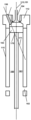
도 1은 본 발명의 일 실시형태에 따른 해양 선박 추진용 2-행정 유니플로 소기식 크로스헤드 내연 엔진(100)의 단면을 개략적으로 도시한다. 2-행정 내연 엔진(100)은 소기공기 시스템(111), 배기가스 리시버(108), 및 터보차저(109)를 포함한다. 2-행정 내연 엔진은 복수의 실린더(101)(단면도에는 단일의 실린더만이 도시됨)를 갖는다. 각각의 실린더(101)는 소기공기를 제공하기 위하여 실린더의 하부 섹션에 배열되는 소기공기 입구(102), 피스톤(103), 실린더의 상부에 배열되는 실린더 커버(112), 실린더 커버(112)에 배열되는 배기 밸브(104), 및 하나 이상의 연료가스 밸브(105)(단지 개략적으로 도시됨)를 포함한다. 소기공기 입구(102)는 소기공기 시스템에 유체 연결(fluidly connected)되어 있다. 피스톤(103)은 가장 낮은 위치(하사점)에 있는 것으로 도시되어 있다. 피스톤(103)은 크랭크샤프트(미도시)에 연결된 피스톤 로드를 갖는다. 피스톤(103)은 하사점과 상사점 사이의 중심 축선(113)을 따라 실린더 내에서 이동 가능하게 배열된다. 중심 축선(113)은 축선방향으로 연장된다. 연료가스 밸브(105)는 연료가스가 소기공기와 혼합될 수 있도록 연료가스 노즐(미도시)을 통해 압축 행정 동안에 피스톤(103)과 실린더 커버(112) 사이에 형성되는 메인 연소 챔버 내로 연료가스를 유입시키도록 구성된다. 연료가스 밸브(105)는 실린더 커버(112) 내에 적어도 부분적으로 배열되고, 연료가스 밸브의 노즐은 제1 노즐 축선(150)을 따라 연료가스를 분사하도록 구성된 제1 노즐 개구부(도시되지 않음)를 갖는다. 제1 노즐 축선(150)은 축선방향에 대해 경사져 있다. 결과적으로, 실린더 커버(120) 내에 연료가스 밸브(105)를 배열함으로써 그리고 연료가스 노즐을 축선방향에 대해 기울임으로써, 결과적인 연료가스 제트는 실린더 벽의 많은 부분에 충돌할 수 있어 연료가스와 소기공기의 균일한 혼합을 초래한다.1 schematically illustrates a cross-section of a two-stroke uniflow scavenging crosshead
내연 엔진(100)은 압축 행정의 끝에서 연료가스와 소기공기의 혼합물을 점화하기 위한 전용의 점화 시스템(116)을 포함한다. 예로서, 전용의 점화 시스템은 정확하게 측정된 소량의 파일럿 연료, 예컨대 중유 또는 마린 디젤 오일을 분사할 수 있는 파일럿 연료 시스템일 수 있으며, 그 양은 정확히 연료가스와 소기공기의 혼합물을 점화할 수 있는 양일 수 있어서 필요한 양의 파일럿 연료만이 사용되도록 할 수 있다. 그러한 파일럿 연료 시스템은 대체 연료(alternative fuel)를 위한 전용의 연료 공급 시스템에 비해 크기가 훨씬 더 작고 정확한 양의 파일럿 연료를 분사하기에 더 적합하며, 대체 연료를 위한 전용의 연료 공급 시스템은 구성요소들의 큰 크기로 인해 이러한 목적에 적합하지 않다. 파일럿 연료는 내연 엔진의 연소 챔버에 유체 연결되는 프리-챔버 내에 분사될 수 있다. 대안적으로, 파일럿 연료는 내연 엔진의 연소 챔버에 유체 연결되는 프리-챔버 세트 내에 분사될 수 있다. 연료가스 밸브(105)는 하사점으로부터 95도 이전, 90도 이전, 또는 85도 이전에 연료가스를 분사하기 시작하도록 구성될 수 있다. 제1 연료가스 밸브는 하사점으로부터 40도 이후, 50도 이후, 또는 60도 이후에 연료가스를 분사하기 시작하도록 구성될 수 있다.The
소기공기 시스템(111)은 소기공기 리시버(110) 및 공기 냉각기(106)를 포함한다. 배기 밸브는 실린더 커버의 중심에 배열되고 배기 밸브의 타이밍은 배기 밸브의 폐쇄 및/또는 개방이 예컨대 실린더 내의 압축비 및/또는 온도를 제어하기 위해 최적화될 수 있도록 가변적일 수 있다.The scavenging
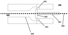
도 2는 본 발명의 일 실시형태에 따른 2-행정 내연 엔진용 연료가스 밸브(200)의 단면을 개략적으로 도시한다. 연료가스 밸브(200)는 도면에서 수평 위치로 도시되어 있지만, 이는 축선방향에 대해 임의의 각도로 배열될 수 있다. 연료가스 밸브(200)는 밸브 샤프트(201), 밸브 플레이트(202), 밸브 시트(203), 및 제1 노즐 개구부(206)를 갖는 연료가스 노즐(204)을 포함한다. 도시된 연료가스 밸브(200)는 단일의 노즐 개구부를 갖지만, 복수의 노즐 개구부를 가질 수도 있다. 밸브 샤프트(201) 및 밸브 플레이트(202)는, 연료가스가 연료가스 밸브(200)를 통해 유동하는 것이 방지되는 폐쇄 위치와, 연료가스가 연료가스 밸브(200)를 통해 유동하는 것이 허용되는 개방 위치와의 사이에서 이동가능하다. 밸브 샤프트(201) 및 밸브 플레이트(202)는 도 2에서 폐쇄 위치로 도시되어 있다. 밸브 샤프트(201) 및 밸브 플레이트(202)는 제어 유닛(미도시)에 의해 제어되는 액추에이터(미도시)에 의해서 폐쇄 위치와 개방 위치 사이에서 이동가능할 수 있다. 제1 노즐 개구부(206)는 제1 노즐 축선(250)을 따라 연료가스를 분사하도록 구성된다.2 schematically illustrates a cross section of a
도 3a 내지 도 3c는 본 발명의 일 실시형태에 따른 2-행정 유니플로 소기식 크로스헤드 내연 엔진의 개략적인 단면을 도시하며, 여기서 도 3a는 피스톤이 하사점에 있는 엔진을 도시하고, 도 3b는 피스톤이 압축 행정의 중간에 있는 엔진을 도시하고, 도 3c는 피스톤이 상사점에 있는 엔진을 도시한다. 2-행정 유니플로 소기식 크로스헤드 내연 엔진은 적어도 하나의 실린더(115), 실린더 커버(112), 피스톤(103), 연료가스 탱크에 연결가능한 연료가스 공급 시스템, 및 소기공기 시스템(미도시)을 포함한다. 실린더는 실린더 벽을 가지며, 실린더 커버(112)는 실린더(115)의 상부에 배열되고 배기 밸브(104)를 가지며, 피스톤(103)은 하사점과 상사점 사이에서 중심 축선(113)을 따라 실린더(115) 내에 이동가능하게 배열된다. 중심 축선(113)은 축선방향으로 연장된다. 소기공기 시스템은 실린더(115)의 하부에 배열된 소기공기 입구(102)를 가지며, 실린더에 대하여 연료가스 공급 시스템은 압축 행정 동안에 연료가스 노즐을 통해 연료가스가 피스톤(103)과 실린더 커버(112) 사이에 형성되는 메인 연소 챔버 내로 유입되도록 구성되는 제1 연료가스 밸브(105)를 포함하여, 연료가스가 소기공기 입구(102)로부터의 소기공기와 혼합될 수 있도록 하고 소기공기와 연료가스의 혼합물이 점화 전에 압축되도록 한다. 제1 연료가스 밸브(105)는 실린더 커버(112)에 적어도 부분적으로 배열된다. 제1 연료가스 밸브(105)의 노즐은 제1 노즐 축선(150)을 따라 연료가스를 분사하도록 구성되는 제1 노즐 개구부를 갖는다. 제1 노즐 축선(150)은 축선방향 및 중심 축선에 대해 경사진다(157). 본 실시형태에서, 이 각도는 대략 22도이다. 그러나, 다른 실시형태에서, 제1 노즐 축선과 축선방향 사이의 각도는 5도 내지 50도, 10도 내지 40도, 또는 15도 내지 30도이다. 제1 노즐 축선(150)은 반경방향 성분(155) 및 축선방향 성분(156)을 갖는다. 실린더(115)는 중심축선(113)을 따라 연장되는 기준 평면(151)에 의해 분할되는 제1 절반부(160) 및 제2 절반부(161)를 갖는다. 기준 평면(151)은 제1 노즐 축선(150)의 반경방향 성분(155)에 대해 수직으로 배열되는데, 즉 기준 평면(151)은 도면의 평면에도 수직이다. 제1 연료가스 밸브(105)의 노즐은 실린더(160)의 제1 절반부 위에서 실린더 커버(112)에 배열되고, 제1 노즐 축선(150)은 (실린더의 내부에서) 실린더의 제1 절반부에서 연장되는 상부 부분(170) 및 (실린더의 내부에서) 실린더의 제2 절반부에서 연장되는 하부 부분(171)을 갖는다. 하사점에서의 피스톤(103)은 제1 노즐 축선(150)의 상부 부분(170) 및 하부 부분(171) 양쪽 모두의 아래에 배열되고(도 3a 참조), 상사점에서의 피스톤(103)은 제1 노즐 축선(150)의 전체 하부 부분(171)의 위에 배열된다(도 3c 참조). 제1 연료가스 밸브(105)는, 피스톤(103)이 제1 노즐 축선의 하부 부분(171)에 도달하기 전에, 즉 피스톤(103)이 도 3b에 도시된 위치에 도달하기 전에, 압축 행정 동안에 연료가스의 분사를 시작하도록 구성된다. 결과적으로, 제1 연료가스 밸브가 실린더의 제1 절반부 위에 배열되고 연료가스를 실린더의 제2 절반부를 향해 분사하도록 구성됨으로써, 결과적인 연료가스의 제트는 메인 연소 챔버 전체에 걸쳐 연료가스를 분배하는 것을 돕는 높은 반경방향 모멘텀으로 실린더 벽에 충돌할 수 있다.3A-3C show schematic cross-sections of a two-stroke uniflow scavenging crosshead internal combustion engine according to one embodiment of the invention, where FIG. 3A shows the engine with the piston at bottom dead center and FIG. 3B shows an engine with the piston in the middle of the compression stroke, and FIG. 3C shows an engine with the piston at top dead center. The two-stroke uniflow scavenging crosshead internal combustion engine includes at least one
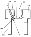
도 4는 본 발명의 일 실시형태에 따른 2-행정 유니플로 소기식 크로스헤드 내연 엔진의 단면을 개략적으로 도시한다. 이 실시형태는, 도 3a 내지 도 3c와 관련하여 개시된 실시형태에 대응하지만, 실린더에 대하여 연료가스 공급 시스템이 연료가스 노즐을 갖는 제2 연료가스 밸브(190)를 더 포함한다는 점에서 상이하다. 제2 연료가스 밸브(190)는 실린더 커버(112)에 적어도 부분적으로 배열되고, 제2 연료가스 밸브의 노즐은 제2 노즐 축선(152)을 따라 연료가스를 분사하도록 구성되는 제1 노즐 개구부를 갖는다. 제2 노즐 축선(152)은 축선방향에 대해 경사진다. 제2 연료가스 밸브(190)의 노즐의 적어도 일부는 실린더의 제2 절반부(161) 위에서 실린더 커버(112)에 배열되고, 제2 노즐 축선은 실린더의 제2 절반부(161)에서 연장되는 상부 부분(173) 및 실린더의 제1 절반부(160)에서 연장되는 하부 부분(174)을 갖는다. 하사점에서 피스톤(103)은 제2 노즐 축선(152)의 상부 부분(173) 및 하부 부분(174) 양쪽 모두의 아래에 배열된다. 상사점에서 피스톤(103)은 제2 노즐 축선(152)의 전체 하부 부분(174) 위에 배열된다. 제2 연료가스 밸브(190)는 피스톤(103)이 제2 노즐 축선(152)의 하부 부분(174)에 도달하기 전에 압축 행정 동안에 연료가스 분사를 시작하도록 구성된다. 결과적으로, 제1 연료가스 밸브(105)가 실린더의 제1 절반부(160) 위에 배열되어 실린더의 제2 절반부(161)를 향하여 연료가스를 지향시킴으로써, 그리고 제2 연료가스 밸브(190)가 실린더의 제2 절반부(161) 위에 배열되어 실린더의 제1 절반부(160)를 향하여 연료가스를 지향시킴으로써, 연료가스와 소기공기의 특히 효과적인 혼합이 초래된다. 본 실시형태에서, 제1 노즐 축선(150)은 제2 노즐 축선(152)과 교차한다. 결과적으로, 제1 연료가스 밸브(105)로부터 기원하는 제트가 제2 연료가스 밸브(190)로부터 기원하는 제트와 충돌하여, 실린더 내의 연료가스의 개선된 분배를 유도하며, 그에 따라 연료가스와 소기공기의 개선된 혼합을 초래한다.4 schematically illustrates a cross-section of a two-stroke uniflow scavenging crosshead internal combustion engine in accordance with one embodiment of the present invention. This embodiment corresponds to the embodiment disclosed with respect to FIGS. 3A to 3C , but differs in that the fuel gas supply system to the cylinder further includes a second
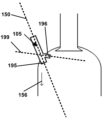
도 5는 본 발명의 일 실시형태에 따른 실린더 커버(112)를 구비한 실린더(115)의 상부를 개략적으로 도시한다. 제1 연료가스 밸브(105)는 실린더 커버(112)에 적어도 부분적으로 배열된다. 제1 연료가스 밸브(105)는 노즐(195)을 갖는다. 제1 연료가스 밸브의 노즐(195)은 축선방향에 대해 경사진 제1 노즐 축선(150)을 따라 연료가스를 분사하도록 구성된 제1 노즐 개구부를 갖는다. 실린더 커버(112)는 배기 밸브(104)를 갖는다. 제1 연료가스 밸브(105)의 노즐(195)은 메인 연소 챔버 내로 돌출되고, 제1 연료가스 밸브(105)는 배기 밸브(104)가 폐쇄되기 전에 연료가스를 분사하기 시작하도록 구성된다. 배기 밸브는 폐쇄 위치와 개방 위치 사이에서 중심 축선을 따라 이동가능한 밸브 플레이트를 가지며, 여기서 배기 밸브 플레이트는 폐쇄 위치에서 제1 높이에 배열되고 개방 위치에서 제2 높이에 배열된다. 배기 밸브(104)는 도 5에서 밸브 플레이트가 개방 위치에 있는 것으로 도시되어 있다. 제1 높이는 제2 높이보다 높고, 노즐(195)의 원위 선단은 제2 높이 아래에, 즉 배기 밸브가 개방될 때 배기 밸브 플레이트의 높이 아래에 배열된다. 결과적으로, 연료가스의 분사는 배기 밸브를 통한 증가된 직접 가스 슬립(direct gas slip)을 초래하지 않고 더 일찍 개시될 수 있다.5 schematically shows the top of a
도 6은 본 발명의 일 실시형태에 따른 연료가스 밸브(105)를 개략적으로 도시한다. 연료가스 밸브(105)는 실린더 커버에 적어도 부분적으로 배치되며 노즐을 갖는다. 연료가스 밸브(105)의 노즐은 축선방향(156)에 대해 경사진 제1 노즐 축선(150)을 따라 연료가스를 분사하도록 구성된 제1 노즐 개구부(195)를 갖는다. 연료가스 밸브(105)의 노즐은 제3 노즐 축선(199)을 따라 연료가스를 분사하도록 구성된 제2 노즐 개구부(196)를 더 갖는다. 제3 노즐 축선(199)은 축선방향(156)에 대해 경사진다. 제3 노즐 축선(199)과 축선방향(156) 사이의 각도는 제1 노즐 축선(150)과 축선방향(156) 사이의 각도보다 크다. 결과적으로, 연료가스의 더 양호한 축선방향 분배가 성취될 수 있어, 제2 노즐 개구부(196)는 연료가스가 연소 챔버의 상부 부분에 제공되는 것을 보장할 수 있다. 제1 노즐 개구부(195)는 제2 노즐 개구부(196)보다 클 수 있어, 제1 노즐 개구부(195)는 연료가스를 제2 노즐 개구부(196)보다 메인 연소 챔버의 보다 큰 부분으로 분배할 수 있다.6 schematically illustrates a
일부 실시형태들이 상세하게 설명되고 도시되었지만, 본 발명은 이것들로 제한되지 않으며, 이하의 청구범위에서 규정된 주제의 범위 내에서 다른 방식으로도 구현될 수 있다. 특히, 또 다른 실시형태가 이용될 수 있고 구조적 및 기능적 변형이 본 발명의 범위를 벗어나지 않고도 이루어질 수 있음을 이해해야 한다.Although some embodiments have been described and shown in detail, the invention is not limited to these, but may be embodied in other ways within the scope of subject matter defined in the following claims. In particular, it should be understood that other embodiments may be utilized and structural and functional modifications may be made without departing from the scope of the present invention.
여러 수단을 열거하는 장치 청구항에 있어서, 이들 수단 중 일부는 하나의 동일한 하드웨어 아이템에 의해 구현될 수 있다. 특정 방안(measures)들이 서로 다른 종속 청구항들에서 인용되거나 상이한 실시형태들에서 설명된다는 사실은 이러한 방안들의 조합이 유리하게 사용될 수 없다는 것을 나타내는 것은 아니다.In the device claim enumerating several means, some of these means may be embodied by one and the same item of hardware. The fact that certain measures are recited in mutually different dependent claims or described in different embodiments does not indicate that a combination of these measures cannot be used to advantage.
본 명세서에서 사용되는 "포함한다(comprises)/포함하는(comprising)"이라는 용어는 언급된 특징, 정수, 단계 또는 구성요소의 존재를 특정하기 위해 사용되지만, 하나 이상의 다른 특징, 정수, 단계, 구성요소 또는 그 그룹의 존재 또는 추가를 배제하지는 않는다는 것이 강조되어야 한다.As used herein, the terms "comprises/comprising" are used to specify the presence of a stated feature, integer, step or component, but not one or more other features, integers, steps, or components. It should be emphasized that the presence or addition of elements or groups thereof is not excluded.
Claims (15)
상기 실린더는 실린더 벽을 가지며, 상기 실린더 커버는 실린더의 상부에 배열되고 배기 밸브를 가지며, 상기 피스톤은 하사점과 상사점 사이에서 중심 축선을 따라 실린더 내에 이동가능하게 배열되며, 상기 소기공기 시스템은 실린더의 하부에 배열되는 소기공기 입구를 가지며, 상기 연료가스 공급 시스템은, 실린더에 대하여, 연료가스 노즐을 통해 압축 행정 동안에 피스톤과 실린더 커버 사이에 형성된 메인 연소 챔버 내로 연료가스를 유입시키도록 구성되어 연료가스가 소기공기 입구로부터의 소기공기와 혼합되도록 할 수 있고 점화 전에 소기공기 및 연료가스의 혼합물이 압축되도록 허용하는 제1 연료가스 밸브를 포함하며,
상기 제1 연료가스 밸브는 상기 실린더 커버에 적어도 부분적으로 배열되고, 상기 제1 연료가스 밸브의 노즐은 제1 노즐 축선을 따라 연료가스를 분사하도록 구성된 제1 노즐 개구부를 갖고, 상기 제1 노즐 축선은 축선방향에 대해 경사지는, 2-행정 유니플로 소기식 크로스헤드 내연 엔진.A two-stroke uniflow scavenging crosshead internal combustion engine comprising at least one cylinder, a cylinder cover, a piston, a fuel gas supply system connectable to a fuel gas tank, and a scavenging air system, comprising:
The cylinder has a cylinder wall, the cylinder cover is arranged on the top of the cylinder and has an exhaust valve, the piston is movably arranged in the cylinder along a central axis between a bottom dead center and a top dead center, and the scavenge air system comprises: and a scavenging air inlet arranged at the bottom of the cylinder, wherein the fuel gas supply system is configured to introduce fuel gas into a main combustion chamber formed between a piston and a cylinder cover during a compression stroke through a fuel gas nozzle, relative to the cylinder. a first fuel gas valve capable of allowing fuel gas to mix with the scavenging air from the scavenging air inlet and allowing the mixture of the scavenging air and fuel gas to be compressed prior to ignition;
The first fuel gas valve is arranged at least partially in the cylinder cover, a nozzle of the first fuel gas valve has a first nozzle opening configured to inject fuel gas along a first nozzle axis, and A two-stroke uniflow scavenging crosshead internal combustion engine, inclined with respect to the axial direction.
상기 실린더는 중심축선을 따라 연장되는 기준 평면에 의해 분할되는 제1 절반부 및 제2 절반부를 가지며, 상기 제1 연료가스 밸브의 노즐의 적어도 일부는 상기 실린더의 제1 절반부 위에서 상기 실린더 커버에 배열되고, 상기 제1 노즐 축선은 상기 실린더의 제1 절반부에서 연장되는 상부 부분 및 상기 실린더의 제2 절반부에서 연장되는 하부 부분을 갖는, 2-행정 유니플로 소기식 크로스헤드 내연 엔진.The method of claim 1,
The cylinder has a first half and a second half divided by a reference plane extending along a central axis, and at least a portion of the nozzle of the first fuel gas valve is attached to the cylinder cover above the first half of the cylinder. wherein the first nozzle axis has an upper portion extending from the first half of the cylinder and a lower portion extending from the second half of the cylinder.
하사점에서 상기 피스톤은 상기 제1 노즐 축선의 상부 부분 및 하부 부분 양쪽 모두의 아래에 배열되고, 상사점에서 상기 피스톤은 상기 제1 노즐 축선의 전체 하부 부분 위에 배열되며, 상기 제1 연료가스 밸브는 상기 피스톤이 상기 제1 노즐 축선의 전체 하부 부분 위에 있기 전에 압축 행정 동안에 연료가스의 분사를 시작하도록 구성되는, 2-행정 유니플로 소기식 크로스헤드 내연 엔진.The method of claim 2,
At bottom dead center the piston is arranged below both an upper portion and a lower portion of the first nozzle axis, at top dead center the piston is arranged above the entire lower portion of the first nozzle axis, and the first fuel gas valve is configured to start injection of fuel gas during a compression stroke before the piston is over the entire lower portion of the first nozzle axis.
상기 연료가스 공급 시스템은, 상기 실린더에 대하여, 연료가스 노즐을 갖는 제2 연료가스 밸브를 포함하고, 상기 제2 연료가스 밸브는 상기 실린더 커버에 적어도 부분적으로 배열되고, 상기 제2 연료가스 밸브의 노즐은 제2 노즐 축선을 따라 연료가스를 분사하도록 구성된 제1 노즐 개구부를 가지며, 상기 제2 노즐 축선은 축선방향에 대해 경사지는, 2-행정 유니플로 소기식 크로스헤드 내연 엔진.According to claim 2 or 3,
The fuel gas supply system includes, relative to the cylinder, a second fuel gas valve having a fuel gas nozzle, the second fuel gas valve being at least partially arranged in the cylinder cover, A two-stroke uniflow scavenging crosshead internal combustion engine, wherein the nozzle has a first nozzle opening configured to inject fuel gas along a second nozzle axis, the second nozzle axis being inclined with respect to the axial direction.
상기 제2 연료가스 밸브의 노즐의 적어도 일부는 상기 실린더의 제2 절반부 위에서 상기 실린더 커버에 배열되고, 상기 제2 노즐 축선은 상기 실린더의 제2 절반부에서 연장되는 상부 부분 및 상기 실린더의 제1 절반부에서 연장되는 하부 부분을 갖는, 2-행정 유니플로 소기식 크로스헤드 내연 엔진.The method of claim 4,
At least a part of the nozzle of the second fuel gas valve is arranged in the cylinder cover above the second half of the cylinder, and the second nozzle axis extends in the second half of the cylinder and the upper part extending in the second half of the cylinder and the second nozzle axis of the cylinder. A two-stroke uniflow scavenging crosshead internal combustion engine having a lower portion extending from one half.
하사점에서 상기 피스톤은 상기 제2 노즐 축선의 상부 부분 및 하부 부분 양쪽 모두의 아래에 배열되고, 상사점에서 상기 피스톤은 상기 제2 노즐 축선의 전체 하부 부분 위에 배열되며, 상기 제2 연료가스 밸브는 상기 피스톤이 상기 제2 노즐 축선의 전체 하부 부분 위에 있기 전에 압축 행정 동안에 연료가스의 분사를 시작하도록 구성되는, 2-행정 유니플로 소기식 크로스헤드 내연 엔진.The method of claim 5,
At bottom dead center, the piston is arranged below both the upper and lower portions of the second nozzle axis, at top dead center, the piston is arranged above the entire lower portion of the second nozzle axis, and the second fuel gas valve is configured to start injection of fuel gas during a compression stroke before the piston is over the entire lower portion of the second nozzle axis.
상기 제1 노즐 축선은 상기 제2 노즐 축선과 교차하는, 2-행정 유니플로 소기식 크로스헤드 내연 엔진.The method of claim 6,
wherein the first nozzle axis intersects the second nozzle axis.
상기 제1 연료가스 밸브는 상기 배기 밸브가 폐쇄되기 전에 연료가스의 분사를 시작하도록 구성되는, 2-행정 유니플로 소기식 크로스헤드 내연 엔진.The method of claim 1,
wherein the first fuel gas valve is configured to start injection of fuel gas before the exhaust valve is closed.
엔진은 X mm의 행정을 갖고 제1 연료가스 밸브의 노즐의 제1 노즐 개구부는 Y의 직경을 가지며, Y는 X의 1% 내지 4%인, 2-행정 유니플로 소기식 크로스헤드 내연 엔진.The method of claim 8,
A two-stroke uniflow scavenging crosshead internal combustion engine, wherein the engine has a stroke of X mm and a first nozzle opening of a nozzle of the first fuel gas valve has a diameter of Y, where Y is 1% to 4% of X.
상기 제1 연료가스 밸브는 하사점으로부터 95도 이전, 90도 이전, 또는 85도 이전에 연료가스의 분사를 시작하도록 구성되는, 2-행정 유니플로 소기식 크로스헤드 내연 엔진.According to claim 8 or 9,
The first fuel gas valve is configured to start injection of fuel gas before 95 degrees, before 90 degrees, or before 85 degrees from bottom dead center.
상기 제1 연료가스 밸브의 노즐은 상기 메인 연소 챔버 내로 돌출하며, 상기 제1 연료가스 밸브는 상기 배기 밸브가 폐쇄되기 전에 연료가스의 분사를 시작하도록 구성되는, 2-행정 유니플로 소기식 크로스헤드 내연 엔진.According to any one of claims 1 to 3,
A nozzle of the first fuel gas valve protrudes into the main combustion chamber, and the first fuel gas valve is configured to start injection of fuel gas before the exhaust valve is closed. internal combustion engine.
상기 배기 밸브는 밸브 플레이트를 가지며, 상기 밸브 플레이트는 폐쇄 위치와 개방 위치 사이에서 상기 중심 축선을 따라 이동가능하며, 상기 배기 밸브의 밸브 플레이트는 폐쇄 위치에서 제1 높이에 그리고 개방 위치에서 제2 높이에 배열되고, 상기 제1 높이는 상기 제2 높이보다 높고, 상기 노즐의 원위 선단은 상기 제2 높이 아래에 배열되는, 2-행정 유니플로 소기식 크로스헤드 내연 엔진.The method of claim 11,
The exhaust valve has a valve plate, the valve plate being movable along the central axis between a closed position and an open position, wherein the valve plate of the exhaust valve is at a first height in the closed position and at a second height in the open position. wherein the first height is higher than the second height and the distal tip of the nozzle is arranged below the second height.
상기 배기 밸브는 밸브 플레이트를 가지며, 상기 밸브 플레이트는 폐쇄 위치와 개방 위치 사이에서 배기 밸브 축선을 따라 이동가능하며, 상기 제1 노즐 개구부의 중심은 상기 중심축선에 대해 제1 거리로 배열되고, 상기 배기 밸브의 밸브 플레이트의 중심은 상기 중심축선에 대해 제2 거리로 배열되며, 상기 제2 거리는 상기 제1 거리보다 큰, 2-행정 유니플로 소기식 크로스헤드 내연 엔진.According to any one of claims 1 to 3,
The exhaust valve has a valve plate, the valve plate being movable between a closed position and an open position along an exhaust valve axis, a center of the first nozzle opening being arranged at a first distance with respect to the central axis, wherein the The center of the valve plate of the exhaust valve is arranged at a second distance with respect to the central axis, the second distance being greater than the first distance.
상기 제1 연료가스 밸브는 분사 기간 동안에 연료가스를 분사하도록 구성되며, 상기 분사 기간은 크랭크 각도가 30도 회전하는데 걸리는 시간보다 짧은, 2-행정 유니플로 소기식 크로스헤드 내연 엔진.According to any one of claims 1 to 3,
The first fuel gas valve is configured to inject fuel gas during an injection period, wherein the injection period is shorter than a time required for a crank angle to rotate 30 degrees.
상기 제1 연료가스 밸브는 제3 노즐 축선을 따라 연료가스를 분사하도록 구성된 제2 노즐 개구부를 가지며 상기 제3 노즐 축선은 축선방향에 대해 경사지며, 상기 제3 노즐 축선과 상기 축선방향 사이의 각도는 상기 제1 노즐 축선과 상기 축선방향 사이의 각도보다 큰, 2-행정 유니플로 소기식 크로스헤드 내연 엔진.According to any one of claims 1 to 3,
The first fuel gas valve has a second nozzle opening configured to inject fuel gas along a third nozzle axis, the third nozzle axis inclined with respect to an axial direction, and an angle between the third nozzle axis and the axial direction. is greater than an angle between the first nozzle axis and the axial direction.
Applications Claiming Priority (2)
| Application Number | Priority Date | Filing Date | Title |
|---|---|---|---|
| DKPA202170417A DK181143B1 (en) | 2021-08-19 | 2021-08-19 | Internal combustion engine |
| DKPA202170417 | 2021-08-19 |
Publications (1)
| Publication Number | Publication Date |
|---|---|
| KR20230028177A true KR20230028177A (en) | 2023-02-28 |
Family
ID=85212914
Family Applications (1)
| Application Number | Title | Priority Date | Filing Date |
|---|---|---|---|
| KR1020220104025A KR20230028177A (en) | 2021-08-19 | 2022-08-19 | Internal combustion engine |
Country Status (4)
| Country | Link |
|---|---|
| JP (1) | JP2023029298A (en) |
| KR (1) | KR20230028177A (en) |
| CN (1) | CN115707862A (en) |
| DK (1) | DK181143B1 (en) |
-
2021
- 2021-08-19 DK DKPA202170417A patent/DK181143B1/en active IP Right Grant
-
2022
- 2022-07-26 CN CN202210883707.6A patent/CN115707862A/en active Pending
- 2022-08-18 JP JP2022130318A patent/JP2023029298A/en active Pending
- 2022-08-19 KR KR1020220104025A patent/KR20230028177A/en unknown
Also Published As
| Publication number | Publication date |
|---|---|
| JP2023029298A (en) | 2023-03-03 |
| DK181143B1 (en) | 2023-02-23 |
| CN115707862A (en) | 2023-02-21 |
| DK202170417A1 (en) | 2023-02-23 |
Similar Documents
| Publication | Publication Date | Title |
|---|---|---|
| KR20220021441A (en) | How to inject ammonia fuel into a reciprocating engine | |
| JP7451463B2 (en) | internal combustion engine | |
| KR102646089B1 (en) | Internal combustion engine | |
| JP6866462B2 (en) | Internal combustion engine | |
| KR20220104054A (en) | internal combustion engine | |
| DK180375B1 (en) | Internal combustion engine | |
| KR20230028177A (en) | Internal combustion engine | |
| KR20210008318A (en) | Internal combustion engine | |
| KR102323480B1 (en) | Internal combustion engine | |
| DK180388B1 (en) | Internal combustion engine | |
| CN114658561A (en) | Method for operating a large diesel engine and large diesel engine |